EP4265967A1 - Air conditioner control method and air conditioner - Google Patents
Air conditioner control method and air conditioner Download PDFInfo
- Publication number
- EP4265967A1 EP4265967A1 EP21922323.7A EP21922323A EP4265967A1 EP 4265967 A1 EP4265967 A1 EP 4265967A1 EP 21922323 A EP21922323 A EP 21922323A EP 4265967 A1 EP4265967 A1 EP 4265967A1
- Authority
- EP
- European Patent Office
- Prior art keywords
- panel
- air conditioner
- purification assembly
- housing
- fan
- Prior art date
- Legal status (The legal status is an assumption and is not a legal conclusion. Google has not performed a legal analysis and makes no representation as to the accuracy of the status listed.)
- Pending
Links
Images




Classifications
-
- F—MECHANICAL ENGINEERING; LIGHTING; HEATING; WEAPONS; BLASTING
- F24—HEATING; RANGES; VENTILATING
- F24F—AIR-CONDITIONING; AIR-HUMIDIFICATION; VENTILATION; USE OF AIR CURRENTS FOR SCREENING
- F24F1/00—Room units for air-conditioning, e.g. separate or self-contained units or units receiving primary air from a central station
- F24F1/0007—Indoor units, e.g. fan coil units
- F24F1/0035—Indoor units, e.g. fan coil units characterised by introduction of outside air to the room
-
- F—MECHANICAL ENGINEERING; LIGHTING; HEATING; WEAPONS; BLASTING
- F24—HEATING; RANGES; VENTILATING
- F24F—AIR-CONDITIONING; AIR-HUMIDIFICATION; VENTILATION; USE OF AIR CURRENTS FOR SCREENING
- F24F1/00—Room units for air-conditioning, e.g. separate or self-contained units or units receiving primary air from a central station
- F24F1/0007—Indoor units, e.g. fan coil units
- F24F1/0071—Indoor units, e.g. fan coil units with means for purifying supplied air
-
- F—MECHANICAL ENGINEERING; LIGHTING; HEATING; WEAPONS; BLASTING
- F24—HEATING; RANGES; VENTILATING
- F24F—AIR-CONDITIONING; AIR-HUMIDIFICATION; VENTILATION; USE OF AIR CURRENTS FOR SCREENING
- F24F11/00—Control or safety arrangements
- F24F11/0001—Control or safety arrangements for ventilation
-
- F—MECHANICAL ENGINEERING; LIGHTING; HEATING; WEAPONS; BLASTING
- F24—HEATING; RANGES; VENTILATING
- F24F—AIR-CONDITIONING; AIR-HUMIDIFICATION; VENTILATION; USE OF AIR CURRENTS FOR SCREENING
- F24F11/00—Control or safety arrangements
- F24F11/30—Control or safety arrangements for purposes related to the operation of the system, e.g. for safety or monitoring
-
- F—MECHANICAL ENGINEERING; LIGHTING; HEATING; WEAPONS; BLASTING
- F24—HEATING; RANGES; VENTILATING
- F24F—AIR-CONDITIONING; AIR-HUMIDIFICATION; VENTILATION; USE OF AIR CURRENTS FOR SCREENING
- F24F11/00—Control or safety arrangements
- F24F11/70—Control systems characterised by their outputs; Constructional details thereof
- F24F11/72—Control systems characterised by their outputs; Constructional details thereof for controlling the supply of treated air, e.g. its pressure
-
- F—MECHANICAL ENGINEERING; LIGHTING; HEATING; WEAPONS; BLASTING
- F24—HEATING; RANGES; VENTILATING
- F24F—AIR-CONDITIONING; AIR-HUMIDIFICATION; VENTILATION; USE OF AIR CURRENTS FOR SCREENING
- F24F11/00—Control or safety arrangements
- F24F11/89—Arrangement or mounting of control or safety devices
-
- F—MECHANICAL ENGINEERING; LIGHTING; HEATING; WEAPONS; BLASTING
- F24—HEATING; RANGES; VENTILATING
- F24F—AIR-CONDITIONING; AIR-HUMIDIFICATION; VENTILATION; USE OF AIR CURRENTS FOR SCREENING
- F24F11/00—Control or safety arrangements
- F24F11/70—Control systems characterised by their outputs; Constructional details thereof
- F24F11/72—Control systems characterised by their outputs; Constructional details thereof for controlling the supply of treated air, e.g. its pressure
- F24F11/74—Control systems characterised by their outputs; Constructional details thereof for controlling the supply of treated air, e.g. its pressure for controlling air flow rate or air velocity
- F24F11/77—Control systems characterised by their outputs; Constructional details thereof for controlling the supply of treated air, e.g. its pressure for controlling air flow rate or air velocity by controlling the speed of ventilators
-
- F—MECHANICAL ENGINEERING; LIGHTING; HEATING; WEAPONS; BLASTING
- F24—HEATING; RANGES; VENTILATING
- F24F—AIR-CONDITIONING; AIR-HUMIDIFICATION; VENTILATION; USE OF AIR CURRENTS FOR SCREENING
- F24F11/00—Control or safety arrangements
- F24F11/0001—Control or safety arrangements for ventilation
- F24F2011/0002—Control or safety arrangements for ventilation for admittance of outside air
-
- F—MECHANICAL ENGINEERING; LIGHTING; HEATING; WEAPONS; BLASTING
- F24—HEATING; RANGES; VENTILATING
- F24F—AIR-CONDITIONING; AIR-HUMIDIFICATION; VENTILATION; USE OF AIR CURRENTS FOR SCREENING
- F24F2140/00—Control inputs relating to system states
- F24F2140/40—Damper positions, e.g. open or closed
Definitions
- the present disclosure relates to the field of electric appliance technologies, and in particular to an air conditioner control method and an air conditioner.
- a fresh air exchange process includes fresh air from an outdoor side being discharged into an indoor side through a fresh air pipe and an air outlet by a fan. Due to the fact that the air from outdoors needs to be filtered through a purification mesh before entering the indoor side, it is necessary to replace the purification mesh after a period of use to keep the incoming air clean. Because the purification mesh is located near the fan and has no safety protection, there are potential safety hazards such as an injury caused by touching a high-speed rotating wind wheel with fingers, when replacing the purification mesh in a running operation of the fresh air module.
- the present disclosure aims at solving at least one of the technical problems in the existing technology to at least a certain extent. Therefore, the present disclosure discloses an air conditioner, in which when a purification assembly needs to be replaced during a running operation of a fresh air module, a fan can be turned off, thus effectively improving safety and being more practical and reliable.
- the present disclosure further discloses a control method suitable for the air conditioner above and a computer-readable storage medium.
- an air conditioner which includes:
- the air conditioner provided by the embodiments of the present disclosure at least has the following beneficial effects.
- the fresh air module is mounted in the machine body, when the purification assembly needs to be replaced, the panel is opened first and then the purification assembly is removed out of the housing, and after the purification assembly is replaced, the fresh air module is concealed in an inner side by the panel in response to the panel being closed.
- the detection device is used to detect the position state of the panel, and the detection device can trigger the air conditioner to control the fan to stop running in response to the panel being opened.
- the detection device is used to detect the position state of the purification assembly, and the detection device can trigger the air conditioner to control the fan to stop running in response to the purification assembly being removed out of the housing.
- the fan can be controlled to stop running by opening the panel or removing the purification assembly. In such a way, a risk of injury caused by touching the fan in a running state with fingers is reduced when replacing the purification assembly.
- the present disclosure plays an effective protection role, improves the safety of the fresh air module when replacing the purification assembly, and is more practical and reliable.
- the detection device includes a position switch.
- the position switch When the position switch is arranged on the machine body, the position switch is configured to detect the position state of the panel, or when the position switch is arranged on the housing, the position switch is configured to detect the position state of the purification assembly.
- the position switch includes a first electrode, a second electrode, a conductive member and an elastic member.
- the conductive member abuts against the panel or the purification assembly.
- the elastic member pushes the conductive member to move, so that the first electrode and the second electrode are connected to control the fan to stop running.
- the panel or the purification assembly is provided with a trigger member configured to abut against the conductive member.
- the machine body or the housing is provided with a through hole configured to guide the trigger member to contact with the conductive member.
- the purification assembly includes a purification mesh.
- the purification assembly includes a mounting frame configured to fix the purification mesh, and the trigger member is arranged on an outer side of the mounting frame.
- the housing defines a cavity configured to accommodate the purification assembly, and the housing is provided with an air inlet and an air outlet, which are communicated with the cavity.
- the housing includes a first volute, a second volute and a frame.
- the frame is connected between the first volute and the second volute, and the detection device is arranged on the frame.
- the panel is provided with an air outlet grille matched with the air outlet.
- one of the panel and the machine body is provided with a buckle, and the other one is provided with a clamping groove adapted with the buckle, so that the panel is buckled with the machine body.
- an embodiment of the present disclosure provides a control method of an air conditioner, where the air conditioner includes:
- control method of the air conditioner provided by the embodiments of the present disclosure at least has the following beneficial effects.
- the current state of the fresh air module is determined to be the turn-on state, which means that, in the case that the fresh air module is turned on, the fan is controlled to stop running once the panel is opened or the purification assembly is removed out of the housing, thus reducing a risk of injury caused by touching the fan in a running state with fingers when replacing the purification assembly.
- the present disclosure plays an effective protection role and improves the safety of the fresh air module when replacing the purification assembly.
- control method further includes the following steps of:
- an embodiment of the present disclosure provides an air conditioner, which includes a memory, a processor, and a computer program stored in the memory and executable by the processor, where the processor is configured to implement the control method of the air conditioner according to the embodiment in the second aspect when executing the computer program.
- an embodiment of the present disclosure provides a computer-readable storage medium, storing a computer-executable instruction, where the computer-executable instruction is configured to execute the control method of the air conditioner according to the embodiment in the second aspect.
- any orientation or position related description such as the orientational or positional relationship, such as up, down, front, rear, and the like, is based on the orientational or positional relationship shown in the accompanying drawings, is only for the purpose of facilitating the description of the present disclosure and simplifying the description, and does not indicate or imply that the device or element must have a specific orientation or position, be constructed and operated in a specific orientation or position, and therefore should not be understood as a limitation to the present disclosure.
- An air conditioner 100 provided by an embodiment of the present disclosure is described with reference to FIG. 1 to FIG. 11 , and the air conditioner 100 may be a split air conditioner or an integral air conditioner.
- a split air conditioner is taken as an example to explain hereinafter.
- the air conditioner 100 includes a machine body 110, the machine body 110 is a wall-mounted indoor machine.
- the machine body 110 is capable of realizing different working modes such as cooling and heating.
- the machine body 110 is provided with a surface frame 111, and a panel 112 connected to the surface frame 111.
- the panel 112 is located on a front side surface of the machine body 110, and the panel 112 is movably connected with the surface frame 111, so that the panel 112 is capable of being opened or closed.
- a fresh air module 200 is mounted in the machine body 110, the fresh air module 200 is communicated with an outdoor environment through an air pipe 240, and the outdoor fresh air is introduced into an indoor environment through the air pipe 240, so to ensure a freshness of indoor air, which is beneficial for reducing a concentration of indoor carbon dioxide, and achieving a fresh air effect in the indoor environment.
- the panel covers the surface frame 111 and is capable of shielding the fresh air module 200 in response to the panel 112 being closed, so that the fresh air module 200 is concealed on an inner side the panel 112, without affecting an appearance of the wall-mounted indoor machine.
- the fresh air module 200 includes a housing 210, a fan 230 and a purification assembly 220.
- the fan 230 and the purification assembly 220 are mounted in the housing 210.
- the fan 230 is configured to suck the outdoor fresh air into the housing 210 through the air pipe 240, and the air is purified and filtered by the purification assembly 220 and then discharged into the indoor environment, thus improving an air freshness and a comfort of the indoor environment.
- the purification assembly 220 is movably connected with the housing 210, the housing 210 is provided with an opening matched with the purification assembly 220, and the purification assembly 220 may be inserted into or removed out of the housing 210 through the opening, so that the purification assembly 220 is convenient to disassemble and replace.
- the fan 230 includes a wind wheel 232 and a motor 231, the motor 231 is fixedly connected with the housing 210, and the wind wheel 232 is driven to rotate at a high speed with the motor 231, so that the outdoor air is capable of entering the housing 210 through the air pipe 240.
- the wind wheel 232 may be a centrifugal wind wheel, and the centrifugal wind wheel has the characteristics of large air volume, large air pressure, short ventilation time and the like, thus being beneficial for improving a ventilation efficiency of fresh air.
- the fresh air module 200 is mounted in the machine body 110.
- the panel 112 is opened first and then the purification assembly 220 is removed out of the housing 210 for replacement, and the panel 112 is closed after the replacement of the purification assembly 220 is finished.
- the wind wheel 232 is in a high-speed rotating state, and there is a risk of injury caused by touching the wind wheel 232 in the high-speed rotating state with fingers when replacing the purification assembly 220.
- the detection device is used to detect the position state of the panel 112 to determine whether the panel 112 is open or closed, when the panel 112 is opened, the panel 112 may trigger the detection device, and the air conditioner 100 controls the fan 230 to stop running. It can be understood that the panel 112 needs to be opened when replacing the purification assembly 220.
- the motor 231 is controlled to stop running, so that the wind wheel 232 stops rotating, thus reducing a risk of touching the wind wheel 232 in the high-speed rotating state with fingers or other objects, playing an effective protection role on the user and the wind wheel 232, effectively improving the safety of the fresh air module 200 when replacing the purification assembly 220, and being more practical and reliable.
- the detection device is mounted in the machine body 110, and the detection device is located at a position of the surface frame 111, so that the detection device is capable of accurately detecting a position change of the panel 112.
- the detection device may be a position sensor, and the position sensor is used to detect position information of the panel 112, and when the panel 112 is far away from the surface frame 111, it can be determined according to a detection signal that the panel 112 is opened, so that a position state of the panel 112 is detected.
- the detection device is not limited to the position of the surface frame 111, and may also be mounted on the panel 112, and the detection device is not limited to the position sensor and may also be a position switch 300.
- a principle of controlling the fan 230 to stop running by the air conditioner 100 may be as follows: when the panel 112 is opened, the detection device is triggered to send out a control signal, a control circuit board of the air conditioner 100 may receive the control signal, and the motor 231 is controlled to be powered off according to the control signal, so that the motor 231 stops running, so as to make the wind wheel 232 stop rotating, thus achieving the purpose of making the wind wheel 232 stop rotating when replacing the purification assembly 220; alternatively, after the detection device is triggered, the motor 231 is directly controlled to be powered off, so as to make the motor 231 stop running, thus achieving the purpose of making the fan 230 stop running. A specific control process will not be repeated.
- the detection device may be triggered in response to the panel 112 being closed, and the air conditioner 100 controls the fan 230 to recover the running state, so that during running of the fresh air module 200, thus reducing the risk of injury caused by touching the wind wheel 232 in the high-speed rotating state with fingers when replacing the purification assembly 220, and the fan automatically resumes the running state after the purification assembly 220 is replaced, thus being safe, reliable and more practical.
- the air conditioner 100 when the air conditioner 100 is turned off, the fresh air module 200 is turned off, and thus the fan 230 isn't in a running operation. At the moment, it is not necessary to control the wind wheel 232 to stop rotating when replacing the purification assembly 220, and the detection device may be in a standby state.
- the panel 112 and the surface frame 111 are fixed by buckling, where an upper end of the panel 112 is hinged with the surface frame 111, so that the panel 112 is capable of rotating around a hinge point, and the panel 112 may be opened or closed.
- a back surface of the panel 112 is provided with a buckle 1122 close to a bottom end position
- the surface frame 111 is provided with a clamping groove 1111 adapted with the buckle 1122, and when the panel 112 is closed, the buckle 1122 is inserted into the clamping groove 1111 for buckling, so that the panel 112 is capable of being buckled on the surface frame 111.
- the panel 112 is capable of being positioned through buckling realized by matching between the buckle 1122 and the clamping groove 1111, and when the panel 112 needs to be opened, only the buckle 1122 needs to be separated from the clamping groove 1111, thus being simple and convenient in operation, and being beneficial for improving an efficiency of replacing the purification assembly 220.
- the buckle 1122 may also be arranged on the surface frame 111, the back surface of the panel 112 is provided with the clamping groove 1111 at the same time, and the panel 112 is fixed on the surface frame 111 through buckling realized by matching between the buckle 1122 and the clamping groove 1111, which is different from the embodiment shown in FIG. 1 and FIG. 2 in that positions of the buckle 1122 and the clamping groove 1111 are interchanged.
- a specific structure is not shown in the accompanying drawings, which will not be repeated herein.
- the detection device is mounted on the housing 210 of the fresh air module 200, and a position state of the purification assembly 220 is detected by the detection device, which means that whether the purification assembly 220 is located in the housing 210 is detected.
- the purification assembly 220 needs to be replaced, the purification assembly 220 is directly pulled out of the housing 210, and then the replaced purification assembly 220 is reinserted into the housing 210.
- the detection device may be triggered in response to the purification assembly 220 being removed out of the housing 210, at the moment, it is judged that the purification assembly 220 is in a state of being separated from the housing 210, and the motor 231 is controlled to stop running, so that the wind wheel 232 stops rotating, thus decreasing a risk of touching the wind wheel 232 in the high-speed rotating state with fingers or other objects, playing an effective protection role on the user and the wind wheel 232, and effectively improving the safety of the fresh air module 200 when replacing the purification assembly 220.
- the detection device when the detection device is mounted in the housing 210, a position state of the purification assembly 220 is capable of being directly detected, and only when the purification assembly 220 is replaced during running of the fresh air module 200, and the panel 112 is opened to pull the purification assembly 220 out of the housing 210, the detection device may be triggered, thus making the fan 230 stop running, which means that, when the purification assembly 220 is removed out of the housing 210, it is considered that a user is replacing the purification assembly 220.
- the fan 230 keeps running, and whether the user is replacing the purification assembly 220 can be accurately identified, thus being more reasonable in structure, and more practical and reliable.
- the detection device is mounted on an inner side of the housing 210, so that the detection device is capable of accurately detecting a position change of the purification assembly 220.
- the detection device may be a position sensor, the position sensor is used to detect a position of the purification assembly 220, when the purification assembly 220 is pulled out, the purification assembly 220 is far away from the position sensor, and at the moment, it can be judged according to a detection signal that the purification assembly 220 is removed out of the housing 210, so as to control the fan 230 to stop running.
- the detection device is not limited to the position sensor, and may also be a position switch 300, and the like.
- a principle of controlling the fan 230 to stop running by the air conditioner 100 may refer to the control principle of the embodiment shown in FIG. 1 and FIG. 2 , which will not be repeated herein.
- the detection device used in the embodiment is the position switch 300
- the position switch 300 includes a first electrode 310, a second electrode 320, a conductive member 330 and an elastic member, where the conductive member 330 is configured to connect the first electrode 310 and the second electrode 320, the conductive member 330 is movably arranged on the inner side of the housing 210, and the conductive member 330 is connected with the elastic member.
- the conductive member 330 When the purification assembly 220 is mounted in the housing 210, the conductive member 330 abuts against the purification assembly 220, and the conductive member 330 is capable of being triggered in response to the purification assembly 220 being removed out of or inserted into the housing 210.
- the conductive member 330 has a conductive function, and the first electrode 310 and the second electrode 320 are connected or disconnected through the conductive member 330 under an elastic function of the elastic member, so that the fan 230 is controlled to start running by connecting the first electrode 310 and the second electrode 320, or stop running by disconnecting the first electrode 310 and the second electrode 320, thus playing a role of on-off control.
- each of the first electrode 310 and the second electrode 320 is connected with a control circuit board of the machine body 110.
- a spring 340 is used as the elastic member, one end of the spring 340 is connected with the housing 210, the other end of the spring is connected with the conductive member 330.
- the conductive member 330 is provided with contact points 331 corresponding to the first electrode 310 and the second electrode 320.
- the purification assembly 220 When the purification assembly 220 is removed out of the housing 210, the purification assembly 220 is separated from the conductive member 330, and at the moment, the conductive member 330 is pushed to move under the elastic function of the elastic member, so that the conductive member 330 is contacted with the first electrode 310 and the second electrode 320 at the same time, thus the first electrode 310 and the second electrode 320 is connected.
- the control circuit board controls the fan 230 to stop running after receiving a connecting signal of the position switch 300, so that during running of the fresh air module 200, the wind wheel 232 is capable of being controlled to stop running in response to the purification assembly 220 being removed out of the housing 210, thus avoiding fingers or other objects from touching the wind wheel 232 in the high-speed rotating state, playing an effective protection role and effectively improving the safety of the fresh air module 200 when replacing the purification assembly 220.
- the purification assembly 220 presses the conductive member 330, so that the contact points 331 of the conductive member 330 are separated from the first electrode 310 and the second electrode 320, thus the first electrode 310 and the second electrode 320 is disconnected and the first electrode and the second electrode will be kept in a disconnected state.
- the control circuit board controls the fan 230 to start running after receiving a disconnecting signal of the position switch 300, and the fan 230 recovers the running state, thus ensuring that the fresh air module 200 is capable of keeping the running state after the purification assembly 220 is replaced.
- the purification assembly 220 is provided with a trigger member 360.
- the trigger member 360 is capable of pushing the conductive member 330 to be separated from the first electrode 310 and the second electrode 320, thus turning off the position switch 300.
- the trigger member 360 is far away from the conductive member 330, so that the conductive member 330 moves towards the first electrode 310 and the second electrode 320 under a function of the spring 340, thus turning on the position switch 300.
- the purification assembly 220 may have structural components such as an electrostatic purification assembly, a high efficiency air filter and an activated carbon filter mesh, which are not specifically limited herein.
- the purification assembly 220 of the embodiment includes a purification mesh 221 and a mounting frame 222.
- the purification mesh 221 is fixedly mounted on the mounting frame 222, the purification mesh 221 is mounted in the housing 210 by the mounting frame 222 or the purification mesh 221 is pulled out of the housing 210.
- the trigger member 360 is arranged on the mounting frame 222. In an embodiment, it is understandable that the trigger member 360 forms a contact protruding from an outer side wall of the mounting frame 222, the contact is not limited to a specific shape.
- the trigger member 360 is located at a position corresponding to the conductive member 330, and when the purification assembly 220 is inserted and mounted in place, the trigger member 360 is capable of correspondingly pushing the conductive member 330 to move towards one side of the spring 340, so that the trigger member 360 and the conductive member 330 are positioned more accurately, thus having a practical and reliable structure.
- a through hole 350 corresponding to the trigger member 360 is arranged in the housing 210.
- the through hole 350 provides a guiding function for the trigger member 360, and when the purification assembly 220 is inserted into the housing 210, the trigger member 360 and the conductive member 330 are capable of being quickly positioned through the through hole 350, so that the trigger member 360 accurately pushes the conductive member 330 to move, thus further improving structural stability and reliability.
- a shape of the trigger member 360 is matched with a shape of the through hole 350.
- the trigger member 360 and the through hole 350 are both circular, which will not be repeated.
- the housing 210 includes a frame 213, a first volute 211 and a second volute 212.
- the frame 213 is connected between the first volute 211 and the second volute 212, where a cavity for accommodating the purification assembly 220 is defined between the frame 213 and the first volute 211, the cavity is communicated with an opening, and the wind wheel 232 and the motor 231 are mounted in the second volute 212.
- the frame 213 is provided with an air guide ring 2132, the frame 213 is provided with an air inlet 2131, the air inlet 2131 is communicated with an outdoor environment through the air pipe 240, the second volute 212 is provided with an air outlet 2121, and the air outlet 2121 is communicated with an indoor environment.
- the motor 231 drives the wind wheel 232 to rotate at a high speed, the outdoor air enters the cavity through the air pipe 240, the air is filtered by the purification mesh 221 and then enters the second volute 212 from the air guide ring 2132, and then the air is discharged into the indoor environment through the air outlet 2121.
- the position switch 300 is arranged on the frame 213, the through hole 350 is arranged in a side wall of the cavity oriented to the opening, and the trigger member 360 is arranged at a position on the mounting frame 222 corresponding to the through hole 350, so that when the mounting frame 222 is inserted from the opening and slides to a bottom end of the cavity along the cavity, the trigger member 360 is capable of crossing through the through hole 350 and pushing the conductive member 330 to move, thus being reasonable in structure, and more convenient to operate.
- the panel 112 is provided with an air outlet grille 1121 matched with the air outlet 2121, so that the filtered air is discharged into the indoor environment from the air outlet grille 1121, thus avoiding the panel 112 from affecting air discharge of the fresh air module 200.
- a gasket 2122 for sealing is arranged between the air outlet 2121 and the air outlet grille 1121.
- the embodiments shown in FIG. 5 to FIG. 11 show that the position switch 300 is mounted on the fresh air module 200, which may trigger and control the fan 230 to stop running in response to the purification assembly 220 being removed out of the housing 210. It is understandable that, as shown in FIG. 1 and FIG. 2 , the position switch 300 shown in the above embodiments may be mounted on the machine body 110, and the fan 230 may be triggered to stop running in response to the panel 112 being opened. At the moment, the trigger member 360 is arranged on a back surface of the panel 112, and a specific structure will not be repeated.
- FIG. 12 to FIG. 14 A control method of an air conditioner provided by an embodiment of the present disclosure is described with reference to FIG. 12 to FIG. 14 , which is suitable for a split air conditioner or an integral air conditioner.
- the control method of the air conditioner provided by the embodiment of the present disclosure includes, but is not limited to, the following steps of:
- the fan 230 when the fan 230 is in a turn-on state, it can be determined that the current state of the fresh air module 200 is the turn-on state. In the case that the fresh air module 200 is in the turn-on state, when the panel 112 is opened, the fan 230 is controlled to stop running, thus reducing a risk of touching the wind wheel 232 in the high-speed rotating state with fingers or other objects, playing an effective protection role, effectively improving the safety of the fresh air module 200 during running when replacing the purification assembly 220, and being more practical and reliable.
- the control method of the air conditioner provided by the embodiment of the present disclosure includes, but is not limited to, the following steps of:
- the fan 230 is controlled to stop running in response to the purification assembly 220 being removed out of the housing 210, thus reducing a risk of touching the wind wheel 232 in the high-speed rotating state with fingers or other objects, playing an effective protection role, effectively improving the safety of the fresh air module 200 when replacing the purification assembly 220, and being more practical and reliable.
- the fan 230 is triggered and controlled to stop running, which means that the purification assembly 220 needs to be replaced before the fan 230 is controlled to be turned off. However, under normal use, the fan 230 may remain in a normal running state.
- the control method includes, but is not limited to, the following steps of:
- the purification assembly 220 may trigger the position switch 300 to turn off, and at the moment, the fan 230 is controlled to start running by a control circuit, so that the fan 230 is capable of running again, thus ensuring that the fresh air module 200 is capable of keeping the running state after the purification assembly 220 is replaced.
- the motor 231 of the fan 230 has different driving frequencies, and the wind wheel 232 has different rotating speeds at different driving frequencies.
- the fresh air module 200 may choose different rotating speeds for ventilation according to use requirements of the user, thus being more comfortable to use.
- the fan 230 includes three different rotating speed gears of high, medium and low rotating speed gears, the higher the rotating speed gear is, the greater the air volume is and the higher the ventilation efficiency is, and when the fresh air module 200 is turned on, the fan 230 runs at the high rotating speed gear.
- a current rotating speed of the fan 230 is recorded as the high rotating speed gear
- the fan 230 is controlled to stop running, and after the purification assembly 220 is replaced and reset, the fan 230 is controlled to start and resume running at the recorded current rotating speed, so that the fresh air module 200 is capable of keeping an original running state after the purification assembly 220 is replaced, deterioration of a comfort degree after the purification assembly 220 is replaced is reduced, and a control mode is more reasonable and practical, thus making the user have better use experience and higher use experience.
- the air conditioner 100 provided by the embodiment of the present disclosure includes a memory, a processor, and a computer program stored in the memory and executable by the processor.
- the processor and the memory may be connected by a bus or other modes.
- the memory is used as a non-transient computer-readable storage medium and may be configured to store a non-transient software program and a non-transient computer-executable program.
- the memory may include a high-speed random-access memory, and may further include a non-transient memory, such as at least one disk memory device, flash memory device, or other non-transient solid-state memory devices.
- the memory may include a memory remotely arranged relative to the processor, and these remote memories may be connected to the processor through a network. Examples of the network above include, but are not limited to, the Internet, the Intranet, a local region network, a mobile communication network, and a combination thereof.
- Non-transient software program and instruction needed to realize the control method of the air conditioner provided by the embodiment above are stored in the memory, and when the non-transient software program and instruction are executed by the processor, the control method of the air conditioner provided by the embodiment above is executed.
- steps S100 to S200 in FIG. 12 , steps S110 to S210 in FIG. 13 , or steps S110 to S211 in FIG. 14 described above are executed.
- the device embodiment described above is only illustrative, where the units described as separate components may or may not be physically separated, which means that the units may be located in one place or distributed to multiple network units. Some or all of the modules may be selected according to actual needs to achieve the objects of the solutions in the embodiments.
- an embodiment of the present disclosure further provides a computer-readable storage medium, the computer-readable storage medium stores a computer-executable instruction, and the computer-executable instruction is executed by one processor or controller.
- the processor may execute the control method of the air conditioner provided by the embodiments above, such as executing the steps S100 to S200 in FIG. 12 , the steps S110 to S210 in FIG. 13 , or the steps S110 to S211 in FIG. 14 described above.
- the term 'computer storage medium' includes a volatile and nonvolatile, removable and non-removable medium implemented in any method or technology for storing information (such as a computer readable instruction, a data structure, a program module, or other data).
- the computer storage media include but are not limited to RAM, ROM, EEPROM, flash storage or other storage technologies, CD-ROM, digital versatile disk (DVD) or other optical disk storage, magnetic box, magnetic tape, magnetic disk storage or other magnetic storage devices, or any other media capable of being used to store desired information and accessed by a computer.
- the communication media include a computer readable instruction, a data structure, a program module or other data in a modulated data signal such as a carrier wave or other transmission mechanism and may include any information delivery medium.
Landscapes
- Engineering & Computer Science (AREA)
- Chemical & Material Sciences (AREA)
- Combustion & Propulsion (AREA)
- Mechanical Engineering (AREA)
- General Engineering & Computer Science (AREA)
- Air Conditioning Control Device (AREA)
Abstract
Description
- The present application claims priority to
Chinese patent application No. 202110125862.7, filed on January 29, 2021 Chinese patent application No. 202120268161.4, filed on January 29, 2021 - The present disclosure relates to the field of electric appliance technologies, and in particular to an air conditioner control method and an air conditioner.
- In an existing air conditioner, a fresh air exchange process includes fresh air from an outdoor side being discharged into an indoor side through a fresh air pipe and an air outlet by a fan. Due to the fact that the air from outdoors needs to be filtered through a purification mesh before entering the indoor side, it is necessary to replace the purification mesh after a period of use to keep the incoming air clean. Because the purification mesh is located near the fan and has no safety protection, there are potential safety hazards such as an injury caused by touching a high-speed rotating wind wheel with fingers, when replacing the purification mesh in a running operation of the fresh air module.
- The present disclosure aims at solving at least one of the technical problems in the existing technology to at least a certain extent. Therefore, the present disclosure discloses an air conditioner, in which when a purification assembly needs to be replaced during a running operation of a fresh air module, a fan can be turned off, thus effectively improving safety and being more practical and reliable.
- The present disclosure further discloses a control method suitable for the air conditioner above and a computer-readable storage medium.
- In a first aspect, an embodiment of the present disclosure provides an air conditioner, which includes:
- a machine body, which includes a panel capable of being opened or closed;
- a fresh air module, arranged on the machine body, where the panel is capable of covering the fresh air module in response to the panel being closed, the fresh air module includes a housing, a fan and a purification assembly, and the purification assembly is detachably arranged in the housing; and
- a detection device, which is configured to detect a position state of the panel to enable the air conditioner to control the fan to stop running in response to the panel being opened, alternatively, the detection device is configured to detect a position state of the purification assembly to enable the air conditioner to control the fan to stop running in response to the purification assembly being removed out of the housing.
- The air conditioner provided by the embodiments of the present disclosure at least has the following beneficial effects.
- The fresh air module is mounted in the machine body, when the purification assembly needs to be replaced, the panel is opened first and then the purification assembly is removed out of the housing, and after the purification assembly is replaced, the fresh air module is concealed in an inner side by the panel in response to the panel being closed. The detection device is used to detect the position state of the panel, and the detection device can trigger the air conditioner to control the fan to stop running in response to the panel being opened. Alternatively, the detection device is used to detect the position state of the purification assembly, and the detection device can trigger the air conditioner to control the fan to stop running in response to the purification assembly being removed out of the housing. Therefore, when the purification assembly needs to be replaced during a running operation of the fresh air module, the fan can be controlled to stop running by opening the panel or removing the purification assembly. In such a way, a risk of injury caused by touching the fan in a running state with fingers is reduced when replacing the purification assembly. The present disclosure plays an effective protection role, improves the safety of the fresh air module when replacing the purification assembly, and is more practical and reliable.
- According to some embodiments of the present disclosure, the detection device includes a position switch. When the position switch is arranged on the machine body, the position switch is configured to detect the position state of the panel, or when the position switch is arranged on the housing, the position switch is configured to detect the position state of the purification assembly.
- According to some embodiments of the present disclosure, the position switch includes a first electrode, a second electrode, a conductive member and an elastic member. The conductive member abuts against the panel or the purification assembly. When the panel is opened or the purification assembly is removed out of the housing, the elastic member pushes the conductive member to move, so that the first electrode and the second electrode are connected to control the fan to stop running.
- According to some embodiments of the present disclosure, the panel or the purification assembly is provided with a trigger member configured to abut against the conductive member.
- According to some embodiments of the present disclosure, the machine body or the housing is provided with a through hole configured to guide the trigger member to contact with the conductive member.
- According to some embodiments of the present disclosure, the purification assembly includes a purification mesh. And the purification assembly includes a mounting frame configured to fix the purification mesh, and the trigger member is arranged on an outer side of the mounting frame.
- According to some embodiments of the present disclosure, the housing defines a cavity configured to accommodate the purification assembly, and the housing is provided with an air inlet and an air outlet, which are communicated with the cavity.
- According to some embodiments of the present disclosure, the housing includes a first volute, a second volute and a frame. The frame is connected between the first volute and the second volute, and the detection device is arranged on the frame.
- According to some embodiments of the present disclosure, the panel is provided with an air outlet grille matched with the air outlet.
- According to some embodiments of the present disclosure, one of the panel and the machine body is provided with a buckle, and the other one is provided with a clamping groove adapted with the buckle, so that the panel is buckled with the machine body.
- In a second aspect, an embodiment of the present disclosure provides a control method of an air conditioner, where the air conditioner includes:
- a machine body, which includes a panel capable of being opened or closed, where the panel is capable of covering the fresh air module in response to the panel being closed;
- a fresh air module, arranged on the machine body, the fresh air module includes a housing, a fan and a purification assembly, and the purification assembly is detachably arranged in the housing; and
- a detection device which is configured to detect a position state of the panel or the purification assembly;
- the control method includes the following steps of:
- determining that a current state of the fresh air module is a turn-on state; and
- controlling the fan to stop running in response to the panel being opened or the purification assembly being removed out of the housing.
- The control method of the air conditioner provided by the embodiments of the present disclosure at least has the following beneficial effects.
- The current state of the fresh air module is determined to be the turn-on state, which means that, in the case that the fresh air module is turned on, the fan is controlled to stop running once the panel is opened or the purification assembly is removed out of the housing, thus reducing a risk of injury caused by touching the fan in a running state with fingers when replacing the purification assembly. The present disclosure plays an effective protection role and improves the safety of the fresh air module when replacing the purification assembly.
- According to some embodiments of the present disclosure, the control method further includes the following steps of:
- recording a current rotating speed of the fan; and
- after the fan is controlled to stop running, in response to the panel being closed or the purification assembly being reset, controlling the fan to start and resume running at the current rotating speed.
- In a third aspect, an embodiment of the present disclosure provides an air conditioner, which includes a memory, a processor, and a computer program stored in the memory and executable by the processor, where the processor is configured to implement the control method of the air conditioner according to the embodiment in the second aspect when executing the computer program.
- In a fourth aspect, an embodiment of the present disclosure provides a computer-readable storage medium, storing a computer-executable instruction, where the computer-executable instruction is configured to execute the control method of the air conditioner according to the embodiment in the second aspect.
- Other features and advantages of the present disclosure will be stated in the following specification, and are partially obvious from the specification, or are learned by implementing the present disclosure.
- The accompanying drawings are provided to further understand the technical solutions of the present disclosure and constitute a part of the specification, and the accompanying drawings are used together with the embodiments of the present disclosure to explain the technical solutions of the present disclosure, but do not constitute a limitation to the technical solutions of the present disclosure, where:
-
FIG. 1 is a schematic structural diagram of an air conditioner according to one embodiment of the present disclosure when a panel is opened; -
FIG. 2 is a schematic structural diagram of the air conditioner from another perspective according to one embodiment of the present disclosure when the panel is opened; -
FIG. 3 is an enlarged schematic diagram of a structure at part a inFIG. 1 ; -
FIG. 4 is an enlarged schematic diagram of a structure at part b inFIG. 2 ; -
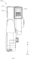
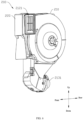
FIG. 5 is a schematic diagram of a front structure of a fresh air module according to one embodiment of the present disclosure; -
FIG. 6 is a schematic diagram of a stereoscopic structure of the fresh air module according to one embodiment of the present disclosure; -
FIG. 7 is a schematic diagram of a side of the fresh air module according to one embodiment of the present disclosure; -
FIG. 8 is a schematic diagram of an exploded fresh air module according to one embodiment of the present disclosure; -
FIG. 9 is a cross-sectional schematic diagram from a direction A-A inFIG. 7 ; -
FIG. 10 is an enlarged schematic diagram of a structure at part c inFIG. 9 ; -
FIG. 11 is a schematic structural diagram of a purification assembly inFIG. 10 in a state of being mounted in place; -
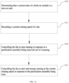
FIG. 12 is a flow chart of a control method of an air conditioner according to one embodiment of the present disclosure; -
FIG. 13 is a flow chart of a control method of an air conditioner according to another embodiment of the present disclosure; and -
FIG. 14 is a flow chart of a control method of an air conditioner according to another embodiment of the present disclosure. -
- 100 refers to air conditioner, 110 refers to machine body, 111 refers to surface frame, 1111 refers to clamping groove, 112 refers to panel, 1121 refers to air outlet grille, and 1122 refers to buckle;
- 200 refers to fresh air module, 210 refers to housing, 211 refers to first volute, 212 refers to second volute, 2121 refers to air outlet, 2122 refers to gasket, 213 refers to frame, 2131 refers to air inlet, 2132 refers to air guide ring, 220 refers to purification assembly, 221 refers to purification mesh, 222 refers to mounting frame, 230 refers to fan, 231 refers to motor, 232 refers to wind wheel, and 240 refers to air pipe;
- 300 refers to position switch, 310 refers to first electrode, 320 refers to second electrode, 330 refers to conductive member, 331 refers to contact point, 340 refers to spring, 350 refers to through hole, and 360 refers to trigger member.
- Embodiments of the present disclosure are described hereinafter in detail, and illustrations of the embodiments are shown in the accompanying drawings, where identical or similar reference numerals denote identical or similar elements or elements having the same or similar functions. The embodiments described hereinafter with reference to the accompanying drawings are exemplary, and are only intended to explain the present disclosure, but should not be understood as limiting the present disclosure.
- In the description of the present disclosure, terms such as first and second in the description are used for distinguishing the technical features only, and cannot be understood as indicating or implying relative importance, implicitly indicating the number of technical features indicated thereby, or implicitly indicating the order of technical features indicated thereby.
- In the description of the present disclosure, it should be understood that any orientation or position related description, such as the orientational or positional relationship, such as up, down, front, rear, and the like, is based on the orientational or positional relationship shown in the accompanying drawings, is only for the purpose of facilitating the description of the present disclosure and simplifying the description, and does not indicate or imply that the device or element must have a specific orientation or position, be constructed and operated in a specific orientation or position, and therefore should not be understood as a limitation to the present disclosure.
- In the description of the present disclosure, it should be noted that, terms such as setup, mounting, and connection should be understood in a broad sense unless otherwise expressly limited, and a person skilled in the art may reasonably determine the specific meaning of the above terms in the present disclosure with reference to the contexts of the technical solutions.
- An
air conditioner 100 provided by an embodiment of the present disclosure is described with reference toFIG. 1 to FIG. 11 , and theair conditioner 100 may be a split air conditioner or an integral air conditioner. A split air conditioner is taken as an example to explain hereinafter. - With reference to
FIG. 1 , theair conditioner 100 includes amachine body 110, themachine body 110 is a wall-mounted indoor machine. Themachine body 110 is capable of realizing different working modes such as cooling and heating. Themachine body 110 is provided with asurface frame 111, and apanel 112 connected to thesurface frame 111. Thepanel 112 is located on a front side surface of themachine body 110, and thepanel 112 is movably connected with thesurface frame 111, so that thepanel 112 is capable of being opened or closed. Afresh air module 200 is mounted in themachine body 110, thefresh air module 200 is communicated with an outdoor environment through anair pipe 240, and the outdoor fresh air is introduced into an indoor environment through theair pipe 240, so to ensure a freshness of indoor air, which is beneficial for reducing a concentration of indoor carbon dioxide, and achieving a fresh air effect in the indoor environment. The panel covers thesurface frame 111 and is capable of shielding thefresh air module 200 in response to thepanel 112 being closed, so that thefresh air module 200 is concealed on an inner side thepanel 112, without affecting an appearance of the wall-mounted indoor machine. - With reference to
FIG. 1 ,FIG. 2 ,FIG. 5 andFIG. 6 , thefresh air module 200 includes ahousing 210, afan 230 and apurification assembly 220. Thefan 230 and thepurification assembly 220 are mounted in thehousing 210. Thefan 230 is configured to suck the outdoor fresh air into thehousing 210 through theair pipe 240, and the air is purified and filtered by thepurification assembly 220 and then discharged into the indoor environment, thus improving an air freshness and a comfort of the indoor environment. Thepurification assembly 220 is movably connected with thehousing 210, thehousing 210 is provided with an opening matched with thepurification assembly 220, and thepurification assembly 220 may be inserted into or removed out of thehousing 210 through the opening, so that thepurification assembly 220 is convenient to disassemble and replace. Thefan 230 includes awind wheel 232 and amotor 231, themotor 231 is fixedly connected with thehousing 210, and thewind wheel 232 is driven to rotate at a high speed with themotor 231, so that the outdoor air is capable of entering thehousing 210 through theair pipe 240. In the embodiment, thewind wheel 232 may be a centrifugal wind wheel, and the centrifugal wind wheel has the characteristics of large air volume, large air pressure, short ventilation time and the like, thus being beneficial for improving a ventilation efficiency of fresh air. - With reference to
FIG. 1 andFIG. 2 , it can be understood that thefresh air module 200 is mounted in themachine body 110. When thepurification assembly 220 needs to be replaced, thepanel 112 is opened first and then thepurification assembly 220 is removed out of thehousing 210 for replacement, and thepanel 112 is closed after the replacement of thepurification assembly 220 is finished. During running of thefresh air module 200, thewind wheel 232 is in a high-speed rotating state, and there is a risk of injury caused by touching thewind wheel 232 in the high-speed rotating state with fingers when replacing thepurification assembly 220. In the embodiment, the detection device is used to detect the position state of thepanel 112 to determine whether thepanel 112 is open or closed, when thepanel 112 is opened, thepanel 112 may trigger the detection device, and theair conditioner 100 controls thefan 230 to stop running. It can be understood that thepanel 112 needs to be opened when replacing thepurification assembly 220. Therefore, during running of thefresh air module 200, when the detection device detects that thepanel 112 is opened, it can be considered that a user needs to replace thepurification assembly 220, and at the moment, themotor 231 is controlled to stop running, so that thewind wheel 232 stops rotating, thus reducing a risk of touching thewind wheel 232 in the high-speed rotating state with fingers or other objects, playing an effective protection role on the user and thewind wheel 232, effectively improving the safety of thefresh air module 200 when replacing thepurification assembly 220, and being more practical and reliable. - With reference to
FIG. 1 andFIG. 3 , it should be noted that, in the embodiment, the detection device is mounted in themachine body 110, and the detection device is located at a position of thesurface frame 111, so that the detection device is capable of accurately detecting a position change of thepanel 112. In an embodiment, the detection device may be a position sensor, and the position sensor is used to detect position information of thepanel 112, and when thepanel 112 is far away from thesurface frame 111, it can be determined according to a detection signal that thepanel 112 is opened, so that a position state of thepanel 112 is detected. Certainly, the detection device is not limited to the position of thesurface frame 111, and may also be mounted on thepanel 112, and the detection device is not limited to the position sensor and may also be aposition switch 300. - In addition, a principle of controlling the
fan 230 to stop running by theair conditioner 100 may be as follows: when thepanel 112 is opened, the detection device is triggered to send out a control signal, a control circuit board of theair conditioner 100 may receive the control signal, and themotor 231 is controlled to be powered off according to the control signal, so that themotor 231 stops running, so as to make thewind wheel 232 stop rotating, thus achieving the purpose of making thewind wheel 232 stop rotating when replacing thepurification assembly 220; alternatively, after the detection device is triggered, themotor 231 is directly controlled to be powered off, so as to make themotor 231 stop running, thus achieving the purpose of making thefan 230 stop running. A specific control process will not be repeated. - It can be understood that, after the
purification assembly 220 is replaced, the detection device may be triggered in response to thepanel 112 being closed, and theair conditioner 100 controls thefan 230 to recover the running state, so that during running of thefresh air module 200, thus reducing the risk of injury caused by touching thewind wheel 232 in the high-speed rotating state with fingers when replacing thepurification assembly 220, and the fan automatically resumes the running state after thepurification assembly 220 is replaced, thus being safe, reliable and more practical. It should be noted that, when theair conditioner 100 is turned off, thefresh air module 200 is turned off, and thus thefan 230 isn't in a running operation. At the moment, it is not necessary to control thewind wheel 232 to stop rotating when replacing thepurification assembly 220, and the detection device may be in a standby state. - With reference to
FIG. 3 and FIG. 4 , thepanel 112 and thesurface frame 111 are fixed by buckling, where an upper end of thepanel 112 is hinged with thesurface frame 111, so that thepanel 112 is capable of rotating around a hinge point, and thepanel 112 may be opened or closed. A back surface of thepanel 112 is provided with abuckle 1122 close to a bottom end position, thesurface frame 111 is provided with aclamping groove 1111 adapted with thebuckle 1122, and when thepanel 112 is closed, thebuckle 1122 is inserted into theclamping groove 1111 for buckling, so that thepanel 112 is capable of being buckled on thesurface frame 111. It can be understood that thepanel 112 is capable of being positioned through buckling realized by matching between thebuckle 1122 and theclamping groove 1111, and when thepanel 112 needs to be opened, only thebuckle 1122 needs to be separated from the clampinggroove 1111, thus being simple and convenient in operation, and being beneficial for improving an efficiency of replacing thepurification assembly 220. - It should be noted that, the
buckle 1122 may also be arranged on thesurface frame 111, the back surface of thepanel 112 is provided with the clampinggroove 1111 at the same time, and thepanel 112 is fixed on thesurface frame 111 through buckling realized by matching between thebuckle 1122 and theclamping groove 1111, which is different from the embodiment shown inFIG. 1 andFIG. 2 in that positions of thebuckle 1122 and theclamping groove 1111 are interchanged. A specific structure is not shown in the accompanying drawings, which will not be repeated herein. - With reference to
FIG. 7 ,FIG. 8 and FIG. 9 , in another embodiment, the detection device is mounted on thehousing 210 of thefresh air module 200, and a position state of thepurification assembly 220 is detected by the detection device, which means that whether thepurification assembly 220 is located in thehousing 210 is detected. When thepurification assembly 220 needs to be replaced, thepurification assembly 220 is directly pulled out of thehousing 210, and then the replacedpurification assembly 220 is reinserted into thehousing 210. It can be understood that, during running of thefresh air module 200, the detection device may be triggered in response to thepurification assembly 220 being removed out of thehousing 210, at the moment, it is judged that thepurification assembly 220 is in a state of being separated from thehousing 210, and themotor 231 is controlled to stop running, so that thewind wheel 232 stops rotating, thus decreasing a risk of touching thewind wheel 232 in the high-speed rotating state with fingers or other objects, playing an effective protection role on the user and thewind wheel 232, and effectively improving the safety of thefresh air module 200 when replacing thepurification assembly 220. - It can be understood that, when the detection device is mounted in the
housing 210, a position state of thepurification assembly 220 is capable of being directly detected, and only when thepurification assembly 220 is replaced during running of thefresh air module 200, and thepanel 112 is opened to pull thepurification assembly 220 out of thehousing 210, the detection device may be triggered, thus making thefan 230 stop running, which means that, when thepurification assembly 220 is removed out of thehousing 210, it is considered that a user is replacing thepurification assembly 220. However, in the case that only thepanel 112 is opened and thepurification assembly 220 is not pulled out, thefan 230 keeps running, and whether the user is replacing thepurification assembly 220 can be accurately identified, thus being more reasonable in structure, and more practical and reliable. - The detection device is mounted on an inner side of the
housing 210, so that the detection device is capable of accurately detecting a position change of thepurification assembly 220. In an embodiment, the detection device may be a position sensor, the position sensor is used to detect a position of thepurification assembly 220, when thepurification assembly 220 is pulled out, thepurification assembly 220 is far away from the position sensor, and at the moment, it can be judged according to a detection signal that thepurification assembly 220 is removed out of thehousing 210, so as to control thefan 230 to stop running. The detection device is not limited to the position sensor, and may also be aposition switch 300, and the like. A principle of controlling thefan 230 to stop running by theair conditioner 100 may refer to the control principle of the embodiment shown inFIG. 1 andFIG. 2 , which will not be repeated herein. - With reference to
FIG. 8 and FIG. 9 , specific description is made by taking the detection device mounted in thehousing 210 as an example, the detection device used in the embodiment is theposition switch 300, and theposition switch 300 includes afirst electrode 310, asecond electrode 320, aconductive member 330 and an elastic member, where theconductive member 330 is configured to connect thefirst electrode 310 and thesecond electrode 320, theconductive member 330 is movably arranged on the inner side of thehousing 210, and theconductive member 330 is connected with the elastic member. When thepurification assembly 220 is mounted in thehousing 210, theconductive member 330 abuts against thepurification assembly 220, and theconductive member 330 is capable of being triggered in response to thepurification assembly 220 being removed out of or inserted into thehousing 210. Theconductive member 330 has a conductive function, and thefirst electrode 310 and thesecond electrode 320 are connected or disconnected through theconductive member 330 under an elastic function of the elastic member, so that thefan 230 is controlled to start running by connecting thefirst electrode 310 and thesecond electrode 320, or stop running by disconnecting thefirst electrode 310 and thesecond electrode 320, thus playing a role of on-off control. - With reference to
FIG. 10 and FIG. 11 , in the embodiment, each of thefirst electrode 310 and thesecond electrode 320 is connected with a control circuit board of themachine body 110. Aspring 340 is used as the elastic member, one end of thespring 340 is connected with thehousing 210, the other end of the spring is connected with theconductive member 330. Theconductive member 330 is provided withcontact points 331 corresponding to thefirst electrode 310 and thesecond electrode 320. When thepurification assembly 220 is removed out of thehousing 210, thepurification assembly 220 is separated from theconductive member 330, and at the moment, theconductive member 330 is pushed to move under the elastic function of the elastic member, so that theconductive member 330 is contacted with thefirst electrode 310 and thesecond electrode 320 at the same time, thus thefirst electrode 310 and thesecond electrode 320 is connected. The control circuit board controls thefan 230 to stop running after receiving a connecting signal of theposition switch 300, so that during running of thefresh air module 200, thewind wheel 232 is capable of being controlled to stop running in response to thepurification assembly 220 being removed out of thehousing 210, thus avoiding fingers or other objects from touching thewind wheel 232 in the high-speed rotating state, playing an effective protection role and effectively improving the safety of thefresh air module 200 when replacing thepurification assembly 220. - With reference to
FIG. 11 , after thepurification assembly 220 is replaced, when thepurification assembly 220 is reinserted into thehousing 210 and reaches a mounting position, that is, when thepurification assembly 220 is mounted in place, thepurification assembly 220 presses theconductive member 330, so that the contact points 331 of theconductive member 330 are separated from thefirst electrode 310 and thesecond electrode 320, thus thefirst electrode 310 and thesecond electrode 320 is disconnected and the first electrode and the second electrode will be kept in a disconnected state. The control circuit board controls thefan 230 to start running after receiving a disconnecting signal of theposition switch 300, and thefan 230 recovers the running state, thus ensuring that thefresh air module 200 is capable of keeping the running state after thepurification assembly 220 is replaced. - With reference to
FIG. 10 and FIG. 11 , in the embodiment, thepurification assembly 220 is provided with atrigger member 360. When thepurification assembly 220 is mounted in thehousing 210, thetrigger member 360 is capable of pushing theconductive member 330 to be separated from thefirst electrode 310 and thesecond electrode 320, thus turning off theposition switch 300. When thepurification assembly 220 is removed out of thehousing 210, thetrigger member 360 is far away from theconductive member 330, so that theconductive member 330 moves towards thefirst electrode 310 and thesecond electrode 320 under a function of thespring 340, thus turning on theposition switch 300. - It should be noted that, the
purification assembly 220 may have structural components such as an electrostatic purification assembly, a high efficiency air filter and an activated carbon filter mesh, which are not specifically limited herein. Thepurification assembly 220 of the embodiment includes apurification mesh 221 and a mountingframe 222. Thepurification mesh 221 is fixedly mounted on the mountingframe 222, thepurification mesh 221 is mounted in thehousing 210 by the mountingframe 222 or thepurification mesh 221 is pulled out of thehousing 210. Thetrigger member 360 is arranged on the mountingframe 222. In an embodiment, it is understandable that thetrigger member 360 forms a contact protruding from an outer side wall of the mountingframe 222, the contact is not limited to a specific shape. Thetrigger member 360 is located at a position corresponding to theconductive member 330, and when thepurification assembly 220 is inserted and mounted in place, thetrigger member 360 is capable of correspondingly pushing theconductive member 330 to move towards one side of thespring 340, so that thetrigger member 360 and theconductive member 330 are positioned more accurately, thus having a practical and reliable structure. - With reference to
FIG. 10 and FIG. 11 , a throughhole 350 corresponding to thetrigger member 360 is arranged in thehousing 210. The throughhole 350 provides a guiding function for thetrigger member 360, and when thepurification assembly 220 is inserted into thehousing 210, thetrigger member 360 and theconductive member 330 are capable of being quickly positioned through the throughhole 350, so that thetrigger member 360 accurately pushes theconductive member 330 to move, thus further improving structural stability and reliability. It is understandable that, a shape of thetrigger member 360 is matched with a shape of the throughhole 350. In some embodiments, thetrigger member 360 and the throughhole 350 are both circular, which will not be repeated. - With reference to
FIG. 8 and FIG. 9 , thehousing 210 includes aframe 213, afirst volute 211 and asecond volute 212. Theframe 213 is connected between thefirst volute 211 and thesecond volute 212, where a cavity for accommodating thepurification assembly 220 is defined between theframe 213 and thefirst volute 211, the cavity is communicated with an opening, and thewind wheel 232 and themotor 231 are mounted in thesecond volute 212. Theframe 213 is provided with anair guide ring 2132, theframe 213 is provided with anair inlet 2131, theair inlet 2131 is communicated with an outdoor environment through theair pipe 240, thesecond volute 212 is provided with anair outlet 2121, and theair outlet 2121 is communicated with an indoor environment. During working, themotor 231 drives thewind wheel 232 to rotate at a high speed, the outdoor air enters the cavity through theair pipe 240, the air is filtered by thepurification mesh 221 and then enters thesecond volute 212 from theair guide ring 2132, and then the air is discharged into the indoor environment through theair outlet 2121. In the embodiment, theposition switch 300 is arranged on theframe 213, the throughhole 350 is arranged in a side wall of the cavity oriented to the opening, and thetrigger member 360 is arranged at a position on the mountingframe 222 corresponding to the throughhole 350, so that when the mountingframe 222 is inserted from the opening and slides to a bottom end of the cavity along the cavity, thetrigger member 360 is capable of crossing through the throughhole 350 and pushing theconductive member 330 to move, thus being reasonable in structure, and more convenient to operate. - In addition, with reference to
FIG. 1 , thepanel 112 is provided with anair outlet grille 1121 matched with theair outlet 2121, so that the filtered air is discharged into the indoor environment from theair outlet grille 1121, thus avoiding thepanel 112 from affecting air discharge of thefresh air module 200. As shown inFIG. 8 , agasket 2122 for sealing is arranged between theair outlet 2121 and theair outlet grille 1121. - It should be noted that, the embodiments shown in
FIG. 5 to FIG. 11 show that theposition switch 300 is mounted on thefresh air module 200, which may trigger and control thefan 230 to stop running in response to thepurification assembly 220 being removed out of thehousing 210. It is understandable that, as shown inFIG. 1 andFIG. 2 , theposition switch 300 shown in the above embodiments may be mounted on themachine body 110, and thefan 230 may be triggered to stop running in response to thepanel 112 being opened. At the moment, thetrigger member 360 is arranged on a back surface of thepanel 112, and a specific structure will not be repeated. - A control method of an air conditioner provided by an embodiment of the present disclosure is described with reference to
FIG. 12 to FIG. 14 , which is suitable for a split air conditioner or an integral air conditioner. - Subsequently, description is made by taking the
air conditioner 100 provided by the embodiment shown inFIG. 1 andFIG. 2 as an example, and with reference toFIG. 12 , the control method of the air conditioner provided by the embodiment of the present disclosure includes, but is not limited to, the following steps of: - step S100: determining that a current state of the
fresh air module 200 is a turn-on state; and - step S200: controlling the
fan 230 to stop running in response to thepanel 112 being opened. - It is understandable that, during running of the
fresh air module 200, thewind wheel 232 is in a high-speed rotating state, and at the moment, there is a risk of injury caused by touching thewind wheel 232 in the high-speed rotating state with fingers when replacing thepurification assembly 220, and the like. However, when thefresh air module 200 is turned off, thefan 230 is in a turn-off state, and at the moment, it is not necessary to control thewind wheel 232 to stop rotating when replacing thepurification assembly 220, thus ending a control program. Therefore, according to the control method provided by the embodiment, a running state of thefresh air module 200 needs to be determined first. In an embodiment, when thefan 230 is in a turn-on state, it can be determined that the current state of thefresh air module 200 is the turn-on state. In the case that thefresh air module 200 is in the turn-on state, when thepanel 112 is opened, thefan 230 is controlled to stop running, thus reducing a risk of touching thewind wheel 232 in the high-speed rotating state with fingers or other objects, playing an effective protection role, effectively improving the safety of thefresh air module 200 during running when replacing thepurification assembly 220, and being more practical and reliable. - Description is made by taking the
air conditioner 100 provided by the embodiment shown inFIG. 9 to FIG. 11 as an example, and with reference toFIG. 13 , the control method of the air conditioner provided by the embodiment of the present disclosure includes, but is not limited to, the following steps of: - step S 110: determining that a current state of the
fresh air module 200 is a turn-on state; and - step S210: controlling the
fan 230 to stop running in response to thepurification assembly 220 being removed out of thehousing 210. - It is understandable that, in the case that the
fresh air module 200 is in the turn-on state, thefan 230 is controlled to stop running in response to thepurification assembly 220 being removed out of thehousing 210, thus reducing a risk of touching thewind wheel 232 in the high-speed rotating state with fingers or other objects, playing an effective protection role, effectively improving the safety of thefresh air module 200 when replacing thepurification assembly 220, and being more practical and reliable. - It should be noted that, only when the
fresh air module 200 is in the turn-on state, and thepanel 112 is opened or thepurification assembly 220 is pulled out of thehousing 210, thefan 230 is triggered and controlled to stop running, which means that thepurification assembly 220 needs to be replaced before thefan 230 is controlled to be turned off. However, under normal use, thefan 230 may remain in a normal running state. - With reference to
FIG. 14 , in some embodiments, taking theair conditioner 100 provided by the embodiment shown inFIG. 9 to FIG. 11 as an example, the control method includes, but is not limited to, the following steps of: - step S 110: determining that a current state of the
fresh air module 200 is a turn-on state; - step S111: recording a current rotating speed of the
fan 230; - step S210: controlling the
fan 230 to stop running in response to thepurification assembly 220 being removed out of thehousing 210; and - step S211: controlling the
fan 230 to start and resume running at the current rotating speed in response to thepurification assembly 220 being reset. - It is understandable that, after the
purification assembly 220 is replaced, when thepurification assembly 220 is reinserted into thehousing 210 and mounted in place, thepurification assembly 220 may trigger theposition switch 300 to turn off, and at the moment, thefan 230 is controlled to start running by a control circuit, so that thefan 230 is capable of running again, thus ensuring that thefresh air module 200 is capable of keeping the running state after thepurification assembly 220 is replaced. - It should be noted that, the
motor 231 of thefan 230 has different driving frequencies, and thewind wheel 232 has different rotating speeds at different driving frequencies. Thefresh air module 200 may choose different rotating speeds for ventilation according to use requirements of the user, thus being more comfortable to use. In an embodiment, thefan 230 includes three different rotating speed gears of high, medium and low rotating speed gears, the higher the rotating speed gear is, the greater the air volume is and the higher the ventilation efficiency is, and when thefresh air module 200 is turned on, thefan 230 runs at the high rotating speed gear. At the moment, a current rotating speed of thefan 230 is recorded as the high rotating speed gear, when replacing thepurification assembly 220, thefan 230 is controlled to stop running, and after thepurification assembly 220 is replaced and reset, thefan 230 is controlled to start and resume running at the recorded current rotating speed, so that thefresh air module 200 is capable of keeping an original running state after thepurification assembly 220 is replaced, deterioration of a comfort degree after thepurification assembly 220 is replaced is reduced, and a control mode is more reasonable and practical, thus making the user have better use experience and higher use experience. - The
air conditioner 100 provided by the embodiment of the present disclosure includes a memory, a processor, and a computer program stored in the memory and executable by the processor. The processor and the memory may be connected by a bus or other modes. - The memory is used as a non-transient computer-readable storage medium and may be configured to store a non-transient software program and a non-transient computer-executable program. In addition, the memory may include a high-speed random-access memory, and may further include a non-transient memory, such as at least one disk memory device, flash memory device, or other non-transient solid-state memory devices. In some embodiments, the memory may include a memory remotely arranged relative to the processor, and these remote memories may be connected to the processor through a network. Examples of the network above include, but are not limited to, the Internet, the Intranet, a local region network, a mobile communication network, and a combination thereof.
- Non-transient software program and instruction needed to realize the control method of the air conditioner provided by the embodiment above are stored in the memory, and when the non-transient software program and instruction are executed by the processor, the control method of the air conditioner provided by the embodiment above is executed. In an embodiment, steps S100 to S200 in
FIG. 12 , steps S110 to S210 inFIG. 13 , or steps S110 to S211 inFIG. 14 described above are executed. - The device embodiment described above is only illustrative, where the units described as separate components may or may not be physically separated, which means that the units may be located in one place or distributed to multiple network units. Some or all of the modules may be selected according to actual needs to achieve the objects of the solutions in the embodiments.
- In addition, an embodiment of the present disclosure further provides a computer-readable storage medium, the computer-readable storage medium stores a computer-executable instruction, and the computer-executable instruction is executed by one processor or controller. In an embodiment, when the computer-executable instruction is executed by one processor in the embodiment of the
air conditioner 100 above, the processor may execute the control method of the air conditioner provided by the embodiments above, such as executing the steps S100 to S200 inFIG. 12 , the steps S110 to S210 inFIG. 13 , or the steps S110 to S211 inFIG. 14 described above. - Those of ordinary skilled in the art can understand that all or some of steps and systems in the method disclosed above can be implemented as software, firmware, hardware and appropriate combinations thereof. Some or all of the physical components can be implemented as software executed by a processor, such as a central processing unit, a digital signal processor or a microprocessor, or implemented as hardware, or implemented as an integrated circuit, such as an application-specific integrated circuit. Such software can be distributed on a computer-readable medium, and the computer-readable medium may include a computer storage medium (or a non-transitory medium) and a communication medium (or a transitory medium). It is well known to those of ordinary skills in the art that the term 'computer storage medium' includes a volatile and nonvolatile, removable and non-removable medium implemented in any method or technology for storing information (such as a computer readable instruction, a data structure, a program module, or other data). The computer storage media include but are not limited to RAM, ROM, EEPROM, flash storage or other storage technologies, CD-ROM, digital versatile disk (DVD) or other optical disk storage, magnetic box, magnetic tape, magnetic disk storage or other magnetic storage devices, or any other media capable of being used to store desired information and accessed by a computer. Furthermore, it is well known to those of ordinary skills in the art that the communication media include a computer readable instruction, a data structure, a program module or other data in a modulated data signal such as a carrier wave or other transmission mechanism and may include any information delivery medium.
- The preferred embodiments of the present disclosure have been described in detail above, but the present disclosure is not limited to the embodiments above. Those skilled in the art may further make various equivalent modifications or substitutions without departing from the spirits of the present disclosure, and these equivalent modifications or substitutions are all included in the scope defined by the claims of the present disclosure.
Claims (14)
- An air conditioner, comprising:a machine body, which comprises a panel capable of being opened or closed, wherein the panel is capable of covering the fresh air module in response to the panel being closed;a fresh air module, which is arranged on the machine body, the fresh air module comprises a housing, a fan and a purification assembly, and the purification assembly is detachably arranged in the housing; anda detection device, wherein the detection device is configured to detect a position state of the panel to enable the air conditioner to control the fan to stop running in response to the panel being opened, or the detection device is configured to detect a position state of the purification assembly to enable the air conditioner to control the fan to stop running in response to the purification assembly being removed out of the housing.
- The air conditioner according to claim 1, wherein the detection device comprises a position switch,in response to the position switch being configured to detect the position state of the panel, the position switch is arranged on the machine body, orin response to the position switch being configured to detect the position state of the purification assembly, the position switch is arranged on the housing.
- The air conditioner according to claim 2, wherein the position switch comprises a first electrode, a second electrode, a conductive member and an elastic member, the conductive member abuts against the panel or the purification assembly, in response to the panel being opened or the purification assembly being removed out of the housing, the elastic member pushes the conductive member to move, so that the first electrode and the second electrode are connected to control the fan to stop running.
- The air conditioner according to claim 3, wherein the panel or the purification assembly is provided with a trigger member configured to abut against the conductive member.
- The air conditioner according to claim 4, wherein the machine body or the housing is provided with a through hole configured to guide the trigger member to contact with the conductive member.
- The air conditioner according to claim 4, wherein the purification assembly comprises a purification mesh, and a mounting frame configured to fix the purification mesh, and the trigger member is arranged on an outer side of the mounting frame.
- The air conditioner according to any one of claims 1 to 6, wherein the housing defines a cavity configured to accommodate the purification assembly, and the housing is provided with an air inlet and an air outlet, which are communicated with the cavity.
- The air conditioner according to claim 7, wherein the housing comprises a first volute, a second volute and a frame, the frame is connected between the first volute and the second volute, and the detection device is arranged on the frame.
- The air conditioner according to claim 7, wherein the panel is provided with an air outlet grille matched with the air outlet.
- The air conditioner according to claim 1, wherein one of the panel and the machine body is provided with a buckle, and the other one is provided with a clamping groove adapted with the buckle, so that the panel is buckled with the machine body.
- A control method of an air conditioner, wherein the air conditioner comprises:a machine body, which comprises a panel capable of being opened or closed;a fresh air module, arranged on the machine body, wherein the panel is capable of shielding the fresh air module in response to the panel being closed, the fresh air module comprises a housing, a fan and a purification assembly, and the purification assembly is detachably arranged in the housing; anda detection device configured to detect a position state of the panel or the purification assembly;the control method comprises the following steps of:determining that a current state of the fresh air module is a turn-on state; andcontrolling the fan to stop running in response to the panel being opened or the purification assembly being removed out of the housing.
- The control method of the air conditioner according to claim 9, further comprising the following steps of:recording a current rotating speed of the fan; andafter the fan is controlled to stop running, in response to the panel being closed or the purification assembly being reset, controlling the fan to start and resume running at the current rotating speed.
- An air conditioner, comprising a memory, a processor, and a computer program stored in the memory and executable by the processor, wherein the processor is configured to implement the control method of the air conditioner according to claim 9 or 10 when executing the computer program.
- A computer-readable storage medium, storing computer-executable instructions, wherein the computer-executable instructions are configured to execute the control method of the air conditioner according to claim 9 or 10.
Applications Claiming Priority (3)
| Application Number | Priority Date | Filing Date | Title |
|---|---|---|---|
| CN202110125862.7A CN112747369B (en) | 2021-01-29 | 2021-01-29 | Air conditioner control method and air conditioner |
| CN202120268161.4U CN214249843U (en) | 2021-01-29 | 2021-01-29 | Air conditioner |
| PCT/CN2021/118015 WO2022160730A1 (en) | 2021-01-29 | 2021-09-13 | Air conditioner control method and air conditioner |
Publications (2)
| Publication Number | Publication Date |
|---|---|
| EP4265967A1 true EP4265967A1 (en) | 2023-10-25 |
| EP4265967A4 EP4265967A4 (en) | 2024-05-22 |
Family
ID=82652936
Family Applications (1)
| Application Number | Title | Priority Date | Filing Date |
|---|---|---|---|
| EP21922323.7A Pending EP4265967A4 (en) | 2021-01-29 | 2021-09-13 | AIR CONDITIONING CONTROL METHODS AND AIR CONDITIONING |
Country Status (2)
| Country | Link |
|---|---|
| EP (1) | EP4265967A4 (en) |
| WO (1) | WO2022160730A1 (en) |
Family Cites Families (16)
| Publication number | Priority date | Publication date | Assignee | Title |
|---|---|---|---|---|
| JP4417709B2 (en) * | 2003-12-25 | 2010-02-17 | 東芝キヤリア株式会社 | Air conditioner |
| US7713339B2 (en) * | 2006-05-26 | 2010-05-11 | 3M Innovative Properties Company | Filter change indicator |
| JP2008249306A (en) * | 2007-03-30 | 2008-10-16 | Aisin Aw Co Ltd | Air cleaner |
| JP5114456B2 (en) * | 2009-06-26 | 2013-01-09 | 日立アプライアンス株式会社 | Air conditioner |
| CN106765968A (en) * | 2016-12-30 | 2017-05-31 | 极客三个爸爸智能环境科技(北京)有限公司 | A kind of autocontrol method of intelligent fresh air cleaning equipment |
| CN108397819A (en) * | 2018-01-12 | 2018-08-14 | 青岛海尔空调器有限总公司 | Cleaning module for air conditioner and the air conditioner including the cleaning module |
| CN209042545U (en) * | 2018-09-20 | 2019-06-28 | 广东美的制冷设备有限公司 | Air conditioner indoor unit and air conditioner |
| CN208920290U (en) * | 2018-09-30 | 2019-05-31 | 珠海格力电器股份有限公司 | Fresh air device and air conditioner indoor unit with same |
| CN209181107U (en) * | 2018-11-08 | 2019-07-30 | 广州华凌制冷设备有限公司 | Air conditioner indoor unit and air conditioner with it |
| CN209181118U (en) * | 2018-11-27 | 2019-07-30 | 广东美的制冷设备有限公司 | Air conditioner indoor unit and air conditioner |
| WO2020180337A1 (en) * | 2019-03-01 | 2020-09-10 | Patel Henry I | Ptac unit with dynamic intelligent air management system |
| CN210638117U (en) * | 2019-07-11 | 2020-05-29 | 青岛海尔空调器有限总公司 | Fresh air conditioner indoor unit |
| CN210601970U (en) * | 2019-10-16 | 2020-05-22 | 广东美的制冷设备有限公司 | Air purification module, air conditioner indoor unit and air conditioner |
| CN111561744A (en) * | 2020-03-30 | 2020-08-21 | 广东美的制冷设备有限公司 | Fresh air module and air conditioner |
| CN212157582U (en) * | 2020-05-29 | 2020-12-15 | 广东美的制冷设备有限公司 | Air pipe, fresh air mechanism and air conditioner |
| CN112747369B (en) * | 2021-01-29 | 2024-06-04 | 广东美的制冷设备有限公司 | Air conditioner control method and air conditioner |
-
2021
- 2021-09-13 WO PCT/CN2021/118015 patent/WO2022160730A1/en not_active Ceased
- 2021-09-13 EP EP21922323.7A patent/EP4265967A4/en active Pending
Also Published As
| Publication number | Publication date |
|---|---|
| WO2022160730A1 (en) | 2022-08-04 |
| EP4265967A4 (en) | 2024-05-22 |
Similar Documents
| Publication | Publication Date | Title |
|---|---|---|
| EP4059401B1 (en) | Self-cleaning drying cleaning device and cleaning storage seat used in same. | |
| KR102586985B1 (en) | Air Conditioner | |
| CN111836999B (en) | Air conditioning equipment | |
| KR101924963B1 (en) | Method for operating home appliance | |
| CN112747369B (en) | Air conditioner control method and air conditioner | |
| EP4265967A1 (en) | Air conditioner control method and air conditioner | |
| CN201054067Y (en) | Projector dust-proof device | |
| CN214249843U (en) | Air conditioner | |
| KR20180110977A (en) | Home appliance | |
| CN210832501U (en) | Device for identifying whether ozone removal filter is installed in place | |
| CN221403161U (en) | Smoke machine module and air conditioner smoke machine | |
| KR102219799B1 (en) | Voice server, voice recognition server system, and method for operating the same | |
| CN210686371U (en) | Smart fan with remove base | |
| KR102219800B1 (en) | Voice server, voice recognition server system, and method for operating the same | |
| CN206515941U (en) | A kind of access control system | |
| CN106352521B (en) | Air conditioner air guide device with moving part, control method and air conditioner | |
| KR20180003645U (en) | Filtering apparatus for box fan | |
| CN216211393U (en) | Fire-fighting early warning monitoring device for transformer substation | |
| CN214577835U (en) | Double-turbine fan ventilation device and dust collector | |
| CN224145913U (en) | Air blower | |
| CN215128001U (en) | Sterilizing dust collector | |
| CN216432013U (en) | Air conditioner indoor unit and fresh air conditioner | |
| CN221007651U (en) | Monitoring device for fire-fighting power supply | |
| CN218299164U (en) | Smoke monitoring equipment for fire fighting | |
| CN215521244U (en) | Water pump with filtering and damping functions |
Legal Events
| Date | Code | Title | Description |
|---|---|---|---|
| STAA | Information on the status of an ep patent application or granted ep patent |
Free format text: STATUS: THE INTERNATIONAL PUBLICATION HAS BEEN MADE |
|
| PUAI | Public reference made under article 153(3) epc to a published international application that has entered the european phase |
Free format text: ORIGINAL CODE: 0009012 |
|
| STAA | Information on the status of an ep patent application or granted ep patent |
Free format text: STATUS: REQUEST FOR EXAMINATION WAS MADE |
|
| 17P | Request for examination filed |
Effective date: 20230717 |
|
| AK | Designated contracting states |
Kind code of ref document: A1 Designated state(s): AL AT BE BG CH CY CZ DE DK EE ES FI FR GB GR HR HU IE IS IT LI LT LU LV MC MK MT NL NO PL PT RO RS SE SI SK SM TR |
|
| DAV | Request for validation of the european patent (deleted) | ||
| DAX | Request for extension of the european patent (deleted) | ||
| A4 | Supplementary search report drawn up and despatched |
Effective date: 20240423 |
|
| RIC1 | Information provided on ipc code assigned before grant |
Ipc: F24F 140/40 20180101ALI20240417BHEP Ipc: F24F 11/00 20180101ALI20240417BHEP Ipc: F24F 11/89 20180101ALI20240417BHEP Ipc: F24F 11/30 20180101ALI20240417BHEP Ipc: F24F 11/72 20180101ALI20240417BHEP Ipc: F24F 8/00 20210101ALI20240417BHEP Ipc: F24F 1/0071 20190101ALI20240417BHEP Ipc: F24F 1/0035 20190101AFI20240417BHEP |