EP4265959A1 - Lamp unit - Google Patents
Lamp unit Download PDFInfo
- Publication number
- EP4265959A1 EP4265959A1 EP21906360.9A EP21906360A EP4265959A1 EP 4265959 A1 EP4265959 A1 EP 4265959A1 EP 21906360 A EP21906360 A EP 21906360A EP 4265959 A1 EP4265959 A1 EP 4265959A1
- Authority
- EP
- European Patent Office
- Prior art keywords
- light
- distribution pattern
- exit surface
- unit
- light distribution
- Prior art date
- Legal status (The legal status is an assumption and is not a legal conclusion. Google has not performed a legal analysis and makes no representation as to the accuracy of the status listed.)
- Withdrawn
Links
Images




Classifications
-
- F—MECHANICAL ENGINEERING; LIGHTING; HEATING; WEAPONS; BLASTING
- F21—LIGHTING
- F21S—NON-PORTABLE LIGHTING DEVICES; SYSTEMS THEREOF; VEHICLE LIGHTING DEVICES SPECIALLY ADAPTED FOR VEHICLE EXTERIORS
- F21S41/00—Illuminating devices specially adapted for vehicle exteriors, e.g. headlamps
- F21S41/20—Illuminating devices specially adapted for vehicle exteriors, e.g. headlamps characterised by refractors, transparent cover plates, light guides or filters
- F21S41/24—Light guides
-
- F—MECHANICAL ENGINEERING; LIGHTING; HEATING; WEAPONS; BLASTING
- F21—LIGHTING
- F21S—NON-PORTABLE LIGHTING DEVICES; SYSTEMS THEREOF; VEHICLE LIGHTING DEVICES SPECIALLY ADAPTED FOR VEHICLE EXTERIORS
- F21S41/00—Illuminating devices specially adapted for vehicle exteriors, e.g. headlamps
- F21S41/10—Illuminating devices specially adapted for vehicle exteriors, e.g. headlamps characterised by the light source
- F21S41/14—Illuminating devices specially adapted for vehicle exteriors, e.g. headlamps characterised by the light source characterised by the type of light source
- F21S41/141—Light emitting diodes [LED]
- F21S41/143—Light emitting diodes [LED] the main emission direction of the LED being parallel to the optical axis of the illuminating device
-
- F—MECHANICAL ENGINEERING; LIGHTING; HEATING; WEAPONS; BLASTING
- F21—LIGHTING
- F21S—NON-PORTABLE LIGHTING DEVICES; SYSTEMS THEREOF; VEHICLE LIGHTING DEVICES SPECIALLY ADAPTED FOR VEHICLE EXTERIORS
- F21S41/00—Illuminating devices specially adapted for vehicle exteriors, e.g. headlamps
- F21S41/20—Illuminating devices specially adapted for vehicle exteriors, e.g. headlamps characterised by refractors, transparent cover plates, light guides or filters
- F21S41/25—Projection lenses
-
- F—MECHANICAL ENGINEERING; LIGHTING; HEATING; WEAPONS; BLASTING
- F21—LIGHTING
- F21S—NON-PORTABLE LIGHTING DEVICES; SYSTEMS THEREOF; VEHICLE LIGHTING DEVICES SPECIALLY ADAPTED FOR VEHICLE EXTERIORS
- F21S41/00—Illuminating devices specially adapted for vehicle exteriors, e.g. headlamps
- F21S41/20—Illuminating devices specially adapted for vehicle exteriors, e.g. headlamps characterised by refractors, transparent cover plates, light guides or filters
- F21S41/25—Projection lenses
- F21S41/27—Thick lenses
-
- F—MECHANICAL ENGINEERING; LIGHTING; HEATING; WEAPONS; BLASTING
- F21—LIGHTING
- F21S—NON-PORTABLE LIGHTING DEVICES; SYSTEMS THEREOF; VEHICLE LIGHTING DEVICES SPECIALLY ADAPTED FOR VEHICLE EXTERIORS
- F21S41/00—Illuminating devices specially adapted for vehicle exteriors, e.g. headlamps
- F21S41/20—Illuminating devices specially adapted for vehicle exteriors, e.g. headlamps characterised by refractors, transparent cover plates, light guides or filters
- F21S41/28—Cover glass
-
- F—MECHANICAL ENGINEERING; LIGHTING; HEATING; WEAPONS; BLASTING
- F21—LIGHTING
- F21S—NON-PORTABLE LIGHTING DEVICES; SYSTEMS THEREOF; VEHICLE LIGHTING DEVICES SPECIALLY ADAPTED FOR VEHICLE EXTERIORS
- F21S41/00—Illuminating devices specially adapted for vehicle exteriors, e.g. headlamps
- F21S41/20—Illuminating devices specially adapted for vehicle exteriors, e.g. headlamps characterised by refractors, transparent cover plates, light guides or filters
- F21S41/2805—Cover glass
-
- F—MECHANICAL ENGINEERING; LIGHTING; HEATING; WEAPONS; BLASTING
- F21—LIGHTING
- F21S—NON-PORTABLE LIGHTING DEVICES; SYSTEMS THEREOF; VEHICLE LIGHTING DEVICES SPECIALLY ADAPTED FOR VEHICLE EXTERIORS
- F21S41/00—Illuminating devices specially adapted for vehicle exteriors, e.g. headlamps
- F21S41/30—Illuminating devices specially adapted for vehicle exteriors, e.g. headlamps characterised by reflectors
- F21S41/32—Optical layout thereof
-
- F—MECHANICAL ENGINEERING; LIGHTING; HEATING; WEAPONS; BLASTING
- F21—LIGHTING
- F21S—NON-PORTABLE LIGHTING DEVICES; SYSTEMS THEREOF; VEHICLE LIGHTING DEVICES SPECIALLY ADAPTED FOR VEHICLE EXTERIORS
- F21S41/00—Illuminating devices specially adapted for vehicle exteriors, e.g. headlamps
- F21S41/30—Illuminating devices specially adapted for vehicle exteriors, e.g. headlamps characterised by reflectors
- F21S41/32—Optical layout thereof
- F21S41/322—Optical layout thereof the reflector using total internal reflection
-
- F—MECHANICAL ENGINEERING; LIGHTING; HEATING; WEAPONS; BLASTING
- F21—LIGHTING
- F21S—NON-PORTABLE LIGHTING DEVICES; SYSTEMS THEREOF; VEHICLE LIGHTING DEVICES SPECIALLY ADAPTED FOR VEHICLE EXTERIORS
- F21S41/00—Illuminating devices specially adapted for vehicle exteriors, e.g. headlamps
- F21S41/40—Illuminating devices specially adapted for vehicle exteriors, e.g. headlamps characterised by screens, non-reflecting members, light-shielding members or fixed shades
- F21S41/43—Illuminating devices specially adapted for vehicle exteriors, e.g. headlamps characterised by screens, non-reflecting members, light-shielding members or fixed shades characterised by the shape thereof
-
- F—MECHANICAL ENGINEERING; LIGHTING; HEATING; WEAPONS; BLASTING
- F21—LIGHTING
- F21S—NON-PORTABLE LIGHTING DEVICES; SYSTEMS THEREOF; VEHICLE LIGHTING DEVICES SPECIALLY ADAPTED FOR VEHICLE EXTERIORS
- F21S41/00—Illuminating devices specially adapted for vehicle exteriors, e.g. headlamps
- F21S41/10—Illuminating devices specially adapted for vehicle exteriors, e.g. headlamps characterised by the light source
- F21S41/14—Illuminating devices specially adapted for vehicle exteriors, e.g. headlamps characterised by the light source characterised by the type of light source
- F21S41/141—Light emitting diodes [LED]
- F21S41/151—Light emitting diodes [LED] arranged in one or more lines
-
- F—MECHANICAL ENGINEERING; LIGHTING; HEATING; WEAPONS; BLASTING
- F21—LIGHTING
- F21W—INDEXING SCHEME ASSOCIATED WITH SUBCLASSES F21K, F21L, F21S and F21V, RELATING TO USES OR APPLICATIONS OF LIGHTING DEVICES OR SYSTEMS
- F21W2102/00—Exterior vehicle lighting devices for illuminating purposes
- F21W2102/10—Arrangement or contour of the emitted light
- F21W2102/13—Arrangement or contour of the emitted light for high-beam region or low-beam region
- F21W2102/135—Arrangement or contour of the emitted light for high-beam region or low-beam region the light having cut-off lines, i.e. clear borderlines between emitted regions and dark regions
- F21W2102/155—Arrangement or contour of the emitted light for high-beam region or low-beam region the light having cut-off lines, i.e. clear borderlines between emitted regions and dark regions having inclined and horizontal cutoff lines
Definitions
- the invention of the present application relates to a light unit including a projection lens.
- a light unit is known related art which is configured in such a manner as to project light from a light source to the front of the unit through a projection lens.
- Patent Literature 1 describes, as a configuration of such a light unit, a configuration in which a light guide that is configured in such a manner as to guide light emitted from a light source into a projection lens is placed between the light source and the projection lens.
- the light unit described in "Patent Literature 1" is configured to include, as light sources thereof, a first light source for forming a low-beam light distribution pattern, and a second light source for forming a high-beam light distribution pattern by being turned on simultaneously with the first light source, and is configured to include, as light guides thereof, a first light guide for guiding light emitted from the first light source, and a second light guide for guiding light emitted from the second light source.
- Patent Literature 1 is configured in such a manner that a cut-off line of the low-beam light distribution pattern is formed with the shape of the lower edge of the exit surface of the first light guide, and is configured in such a manner that, upon the formation, a part of the light from the first light source that has entered the first light guide is totally reflected by the underside of the first light guide.
- Patent Literature 1 JP-A-2017-199660
- Such a light unit includes a light guide formed of a single member, the number of components of the light unit can be reduced. As a result, a reduction in the cost of the light unit can be promoted.
- a light guide is configured to include a first exit surface for emitting light for a low-beam light distribution pattern and a second exit surface for emitting light for an additional light distribution pattern that is added to the low-beam light distribution pattern to form a high-beam light distribution pattern, and further configured in such a manner as to form the second exit surface at a position displaced toward the back of the unit relative to the first exit surface, it is possible to form a cut-off line of the low-beam light distribution pattern by use of the lower edge of the first exit surface.
- the light guide is formed with a connection surface extending toward the back of the unit from the lower edge of the first exit surface to the upper edge of the second exit surface, but the light from the second light source that has been emitted through the second exit surface and reached the connection surface results in re-entering the light guide through the connection surface. Therefore, the luminous flux utilization factor for the light emitted from the second light source decreases. Consequently, the brightness of the additional light distribution pattern decreases. Therefore, the high-beam light distribution pattern results in being unable to be formed with desired luminous intensity distribution.
- the invention of the present application has been made in view of such circumstances, and an object thereof is to provide a light unit including a projection lens, which can form a low-beam light distribution pattern and a high-beam light distribution pattern appropriately in addition to promoting cost reduction based on a reduction in the number of components of the light unit.
- the invention of the present application aims to achieve the above object by devising a configuration of a light guide placed between a light source and a projection lens.
- a light unit configured to project light from a light source to the front of the unit through a projection lens, in which a light guide configured to guide the light emitted from the light source into the projection lens is placed between the light source and the projection lens, the light source includes a first light source for forming a low-beam light distribution pattern, and a second light source for forming a high-beam light distribution pattern by being turned on simultaneously with the first light source, the light guide includes a first exit surface for emitting light for the low-beam light distribution pattern, and a second exit surface for emitting light for an additional light distribution pattern that is added to the low-beam light distribution pattern to form the high-beam light distribution pattern, the second exit surface is formed below the first exit surface and at a position displaced toward the back of the unit relative to the first exit surface, the light guide includes a connection surface extending toward the back of the unit from a lower edge of the first exit surface to an upper edge of the second exit surface,
- connection surface is formed in such a manner as to extend toward the back of the unit from the lower edge of the first exit surface to the upper edge of the second exit surface, the specific placement, surface shape, and the like of the connection surface are not particularly limited.
- the "mirror surface portion" may be provided all over the connection surface, or may be provided only on a part of the connection surface.
- the specific configuration of the "mirror surface portion” is not particularly limited.
- a mirror surface portion formed by aluminum vacuum vapor deposition, or a mirror surface portion formed by attaching an aluminum foil thereto can be adopted.
- a light unit according to the invention of the present application is configured in such a manner as to project light from a light source to the front of the unit through a projection lens.
- a light guide that is configured in such a manner as to guide the light emitted from the light source into the projection lens is placed between the light source and the projection lens.
- the light guide controlling the light that enters the projection lens.
- the light source includes a first light source for forming a low-beam light distribution pattern, and a second light source for forming a high-beam light distribution pattern by being turned on simultaneously with the first light source
- the light guide includes a first exit surface for emitting light for the low-beam light distribution pattern, and a second exit surface for emitting light for an additional light distribution pattern that is added to the low-beam light distribution pattern to form the high-beam light distribution pattern.
- the second exit surface of the light guide Upon the formation, below the first exit surface, the second exit surface of the light guide is displaced toward the back of the unit relative to the first exit surface. Consequently, a cut-off line of the low-beam light distribution pattern can be formed based on the shape of a lower edge of the first exit surface.
- the light guide includes a connection surface extending toward the back of the unit from the lower edge of the first exit surface to an upper edge of the second exit surface, and the connection surface is provided with a mirror surface portion. Consequently, the following operations and effects can be obtained.
- the high-beam light distribution pattern results in being unable to be formed with desired luminous intensity distribution.
- connection surface of the light guide is provided with the mirror surface portion; therefore, it is possible to avoid or restrain the light from the second light source that has been emitted through the second exit surface and reached the connection surface from re-entering the light guide through the connection surface. Consequently, it is possible to form the high-beam light distribution pattern with desired luminous intensity distribution.
- the light guide is formed of a single member; therefore, it is possible to obtain the above operations and effects in addition to promoting cost reduction based on a reduction in the number of components of the light unit.
- the light unit including the projection lens can form the low-beam light distribution pattern and the high-beam light distribution pattern appropriately in addition to promoting cost reduction based on a reduction in the number of components of the light unit.
- connection surface of the light guide is further configured to include a region located near a back focal point of the projection lens as a light transmission portion, the following operations and effects can be obtained.
- the focal point neighboring portion of the light guide which is located near the back focal point of the projection lens, may become hot due to concentration of, for example, sunlight that enters from the outside of the light unit through the projection lens.
- the light guide is likely to be eroded depending on the material of the light guide.
- the mirror surface portion is provided all over the connection surface of the light guide, heat is more likely to be trapped in the focal point neighboring portion of the light guide. Therefore, erosion becomes more likely to occur.
- the light guide is configured in such a manner that the connection surface includes the region located near the back focal point of the projection lens, as the light transmission portion, a part of, for example, sunlight that enters the focal point neighboring portion of the light guide can be emitted to a lower space without being reflected by the connection surface. Consequently, heat can be made less likely to be trapped in the focal point neighboring portion. Therefore, occurrence of erosion can be effectively restrained.
- connection surface of the light guide is further configured to include a neighboring region of a front edge of the connection surface, as a light transmission portion, the following operations and effects can be obtained.
- the light from the second exit surface that has been emitted through the second exit surface and reached the neighboring region of the front edge of the connection surface results in re-entering the light guide through the light transmission portion of the neighboring region of the front edge, and being emitted to the front of the unit through a neighboring region of the lower edge of the first exit surface.
- the emitted light is then projected to the front of the unit through the projection lens, which enables forming the additional light distribution pattern whose lower edge portion partially overlaps a neighboring region of the cut-off line of the low-beam light distribution pattern. Therefore, the high-beam light distribution pattern can be formed as a substantially uniform light distribution pattern in which the low-beam light distribution pattern and the additional light distribution pattern are smoothly connected.
- the front-to-back width of the neighboring region of the front edge is further configured in such a manner as to be set at a value equal to or less than 1/3 of the front-to-back width of the connection surface, the high-beam light distribution pattern can be formed with more preferable luminous intensity distribution.
- the light guide further includes a resin member
- the focal point neighboring portion of the light guide is likely to be eroded due to, for example sunlight that enters from the outside of the light unit through the projection lens. Therefore, it is particularly effective to form the region on the connection surface, the region being located near the back focal point of the projection lens, as the light transmission portion.
- the light guide is further configured to include a plurality of entrance portions for letting in light emitted from the plurality of the respective first light sources, it is possible to easily and clearly form the low-beam light distribution pattern in a desired shape.
- Fig. 1 is a side cross-sectional view illustrating a vehicle light 100 including a light unit 10 according to one embodiment of the invention of the present application.
- Fig. 2 is an arrow view in direction II of Fig. 1 .
- a direction represented by X is "front of the unit”
- a direction represented by Y is “left” ("right” in a front view of the unit) orthogonal to "front of the unit”
- a direction represented by Z is "upward”. The same applies to the drawings other than Figs. 1 and 2 .
- the vehicle light 100 is a headlamp provided at the front end of a vehicle, and is configured in such a manner that the light unit 10 is housed in a light chamber formed by a lamp body 102 and a translucent cover 104 with an optical axis of the light unit 10 adjusted to substantially align a front-and back direction of the light unit 10 (that is, a front-and back direction of the unit) with a front-and back direction of the vehicle.
- the light unit 10 is a projector light unit, and is configured in such a manner that a low-beam light distribution pattern and a high-beam light distribution pattern (which are described below) can be formed by projecting light from a light source 20 to the front of the unit through a projection lens 30.
- the projection lens 30 has an optical axis Ax extending in a front-and-back direction of the unit, and is configured in such a manner as to form the light distribution patterns by inversely projecting projection images formed in the back focal plane of the projection lens 30.
- a light guide 40 that is configured in such a manner as to guide the light emitted from the light source 20 into the projection lens 30 is placed between the projection lens 30 and the light source 20 placed in the back of the unit. The projection image is then formed in the light guide 40.
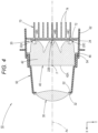
- Fig. 3 is a side cross-sectional view illustrating the light unit 10 alone.
- Fig. 4 is a cross-sectional view taken along line IV-IV of Fig. 3
- Fig. 5 is a cross-sectional view taken along line V-V of Fig. 3
- Fig. 6 is a cross-sectional view taken along line VI-VI of Fig. 3 .
- Fig. 7 is an exploded perspective view illustrating the light unit 10 as viewed obliquely from the front
- Fig. 8 is an exploded perspective view illustrating the light unit 10 as viewed obliquely from the back.
- the projection lens 30 is a biconvex aspherical lens having an outer peripheral flange portion 32, and is formed of a colorless and transparent acrylic resin member.
- the projection lens 30 is supported at the outer peripheral flange portion 32 by a lens holder 50.
- the lens holder 50 is a tubular member extending in the front-and-back direction of the unit, is formed of an opaque polycarbonate resin member, and includes an annular lens support portion 52 formed at the front end of the lens holder 50.
- the projection lens 30 is fixed to the lens holder 50 by laser welding with the outer peripheral flange portion 32 pressed against the lens support portion 52 of the lens holder 50 from the front of the unit.
- the projection lens 30 is positioned relative to the lens holder 50 in a direction orthogonal to the front-and-back direction of the unit by engaging a pair of upper and lower positioning pins 52a and 52b formed on the lens support portion 52 of the lens holder 50 with a positioning hole 32a and a positioning groove 32b that are formed in the upper and lower parts of the outer peripheral flange portion 32 of the projection lens 30.
- the light source 20 includes four light-emitting elements 22A, 22B, 22C, and 22D mounted on a common board 24.
- Each of the four light-emitting elements 22A to 22D is a white light-emitting diode having a horizontal rectangular light-emitting surface, and is placed with its light-emitting surface facing the front of the unit.
- three light-emitting elements 22A to 22C are configured in such a manner as to be turned on to form the low-beam light distribution pattern, and the remaining one light-emitting element 22D is additionally turned on to form the high-beam light distribution pattern.
- the three light-emitting elements 22A to 22C are placed at a position directly above the optical axis Ax of the projection lens 30 and positions separated from each other at a fixed interval on the left and right sides of the one directly above the optical axis Ax.
- the light-emitting element 22D is placed at a position directly below the optical axis Ax.
- the board 24 is supported by the lens holder 50, placed in such a manner as to extend along a vertical plane orthogonal to the optical axis Ax of the projection lens 30 (which is described below).
- a connector 26 electrically connected to the four light-emitting elements 22A to 22D via a conductive pattern (not illustrated) is mounted at the bottom middle end of the front surface of the board 24. It is configured in such a manner that power is supplied to the four light-emitting elements 22A to 22D by attaching a power supply connector (not illustrated) to the connector 26.
- the light guide 40 is formed of a colorless and transparent polycarbonate resin member.
- the light guide 40 includes a first exit surface 42A for emitting light for the low-beam light distribution pattern and a second exit surface 42B for emitting light for an additional light distribution pattern that is added to the low-beam light distribution pattern to form the high-beam light distribution pattern.
- the first exit surface 42A is located in the upper part of the front surface of the light guide 40, and is formed in such a manner as to extend along the back focal plane of the projection lens 30. As illustrated in Fig. 7 , the first exit surface 42A has a substantially horizontal rectangular outer shape having chamfered top left and right corners. As illustrated in Figs. 2 and 3 , a lower edge 42Aa of the first exit surface 42A is formed in such a manner as to pass near above a back focal point F of the projection lens 30 and extend in the horizontal direction at different heights on the left and right sides.
- the second exit surface 42B is located in the lower part of the front surface of the light guide 40, and is formed at a position a fixed distance away from the back focal plane of the projection lens 30 toward the back of the unit in such a manner as to extend along a plane slightly inclined backward relative to the vertical plane orthogonal to the optical axis Ax of the projection lens 30.
- the second exit surface 42B is located directly below the optical axis Ax and has a substantially horizontal elliptical outer shape with its upper part cut away.
- the light guide 40 includes a block portion 42 extending toward the back of the unit while substantially maintaining the outer shape of the first exit surface 42.
- the underside of the block portion 42 is formed as a connection surface 42C extending in the horizontal direction toward the back of the unit from the lower edge 42Aa of the first exit surface 42A to an upper edge 42Ba of the second exit surface 42B.
- the connection surface 42C is provided with a mirror surface portion 42C1 (which is described below).
- the light guide 40 includes four entrance portions 44A, 44B, 44C, and 44D for letting in the light emitted from the four light-emitting elements 22A, 22B, 22C, and 22D, respectively.
- three entrance portions 44A to 44C are formed in such a manner as to be located on the front side of the unit relative to the three light-emitting elements 22A to 22C, respectively, and on the back side of the unit relative to the block portion 42.
- the remaining one entrance portion 44D is formed in such a manner as to be located on the front side of the unit relative to the light-emitting element 22D and on the back side of the unit relative to the second exit surface 42B.
- the three entrance portions 44A to 44C are configured in such a manner as to let in the light emitted from the three light-emitting elements 22A to 22C, respectively, and then guide the light into the block portion 42 directly or after totally reflecting the light by the entrance portions 44A to 44C.
- the block portion 42 is configured in such a manner as to guide the incident light from the three entrance portions 44A to 44C to the first exit surface 42A. It is configured in such a manner that upon guiding the light, the light that has reached the connection surface 42C is totally reflected by the connection surface 42C and then guided to the first exit surface 42A.
- the entrance portion 44D is configured in such a manner as to let in the light emitted from the light-emitting element 22D and then guide the light to the second exit surface 42B directly or after totally reflecting the light thereby.
- the light from the light-emitting element 22B that has entered the light guide 40 from the entrance portion 44B located directly above the optical axis Ax is emitted toward the projection lens 30 through the first exit surface 42A, and is projected to the front of the unit from the projection lens 30 as substantially downward light.
- the light from the light-emitting element 22D that has entered the light guide 40 from the entrance portion 44D is emitted toward the projection lens 30 through the second exit surface 42B, and is projected to the front of the unit from the projection lens 30 as substantially upward light.
- an outer peripheral flange portion 46 extending along the vertical plane orthogonal to the optical axis Ax is formed on the top, left, and right sides at the back end of the block portion 42 in the light guide 40.
- the light guide 40 is supported by the lens holder 50 at the outer peripheral flange portion 46, housed in the internal space of the lens holder 50.
- the lens holder 50 is provided with a light guide support portion 54 extending along the outer peripheral flange portion 46 of the light guide 40.
- the light guide 40 is fixed to the lens holder 50 by laser welding with the outer peripheral flange portion 46 pressed against the back surface of the light guide support portion 54 of the lens holder 50 from the back of the unit.
- the light unit 10 includes a heat sink 70 made of metal (for example, aluminum) for dissipating heat generated by the four light-emitting elements 22A, 22B, 22C, and 22D.
- a heat sink 70 made of metal (for example, aluminum) for dissipating heat generated by the four light-emitting elements 22A, 22B, 22C, and 22D.
- the heat sink 70 includes a main portion 72 extending along the vertical plane orthogonal to the optical axis Ax of the projection lens 30, and a plurality of radiating fins 74 extending from the main portion 72 toward the back of the unit along the vertical plane.
- the heat sink 70, together with the board 24, is supported by the lens holder 50 with the front surface of the main portion 72 in surface contact with the back surface of the board 24.
- the board 24 and the heat sink 70 are supported on the lens holder 50 by mechanical fastening. Specifically, the board 24 and the heat sink 70 are screwed to the lens holder 50 in two places on the left and right sides to be fixed to the lens holder 50.
- a pair of left and right screw bosses 56 is formed in the lens holder 50, and pairs of left and right screw insertion holes 24a and 72a for inserting screws 76 for fastening together are formed in the board 24 and the main portion 72 of the heat sink 70.
- the lens holder 50 is provided with stepped positioning pins 58 extending toward the back of the unit, in three places at the top middle end and at the bottom left and right ends.
- the board 24 is provided with positioning holes 24b in three places at the top middle end and at the bottom left and right ends. It is configured in such a manner that distal end small-diameter portions 58a of the stepped positioning pins 58 are inserted into the positioning holes 24b of the board 24, respectively, and the board 24 comes into contact with distal end flat portions 58b of the stepped positioning pins 58 to determine the position of the board 24 relative to the lens holder 50 in the front-and-back direction of the unit and in the direction orthogonal to the front-and-back direction of the unit.
- the upper wall portion of the lens holder 50 is provided with a reinforcing rib 60 having a substantially U shape that is formed in such a manner as to be connected to the base portion of the stepped positioning pin 58.
- the lens holder 50 is provided with a pair of left and right positioning portions 62 for determining the position of the heat sink 70 in the direction orthogonal to the front-and-back direction of the unit.
- These positioning portions 62 are formed in such a manner as to extend toward the back of the unit by extending over the upper and lower end surfaces of the main portion 72 at positions near the left and right end surfaces of the main portion 72 of the heat sink 70.
- an L-shaped notch 62a is formed at each of the upper and lower ends of the pair of left and right positioning portions 62.
- the board 24 is thereby brought into contact with the notches 62a in the four places to determine the position of the board 24 in the front-and-back direction of the unit when the board 24 and the heat sink 70 are fixed to the lens holder 50.
- Fig. 9 is a detailed view of main elements of Fig. 3 .
- Fig. 10 is a detailed view of part X of Fig. 9 .
- Fig. 11(a) is a cross-sectional view taken along line XIa-XIa of Fig. 10 .
- the mirror surface portion 42C1 is provided all over the connection surface 42C forming the underside of the block portion 42 of the light guide 40.
- the mirror surface portion 42C1 is formed by, for example, depositing aluminum on the connection surface 42 in a vacuum.
- the light from the light-emitting element 22D that has entered the light guide 40 from the entrance portion 44D is emitted toward the projection lens 30 through the second exit surface 42B, and thereafter most of the light directly reaches the projection lens 30.
- a part of the light reaches the connection surface 42C.
- the mirror surface portion 42C1 is not provided on the connection surface 42C, the light that has reached the connection surface 42C re-enters the block portion 42 through the connection surface 42C as indicated by a chain double-dashed line in the drawings, and is then emitted as diagonally upward light through the first exit surface 42A in a direction deviating from the projection lens 30.
- the mirror surface portion 42C1 is actually provided all over the connection surface 42C. Therefore, the light that has reached the connection surface 42C is reflected by the mirror surface portion 42C1 and reaches the projection lens 30 as diagonally downward light.
- Figs. 12(a) and 12(b) are diagrams illustrating, in a perspective manner, light distribution patterns that are formed on a virtual vertical screen placed 25 m ahead of the vehicle by use of the light projected to the front of the unit from the light unit 10 of the vehicle light 100.
- Fig. 12(a) is a diagram illustrating a low-beam light distribution pattern PL
- Fig. 12(b) is a diagram illustrating a high-beam light distribution pattern PH1.
- the low-beam light distribution pattern PL is a low-beam light distribution pattern of left light distribution, and includes, at the upper edge thereof, cut-off lines CL1 and CL2 on the right and left sides that are at different heights.
- the cut-off lines CL1 and CL2 extend in the horizontal direction at different heights on the right and left sides across line V-V passing in the vertical direction through H-V, which is the vanishing point in the front direction of the light.
- An opposite lane on the right side of line V-V is formed as the lower cut-off line CL1
- the own driving lane on the left side of line V-V is formed as the upper cut-off line CL2 stepped up from the lower cut-off line CL1 via an inclined portion.
- an elbow point E which is an intersection point between the lower cut-off line CL1 and line V-V, is located approximately 0.5 to 0.6° below H-V
- the low-beam light distribution pattern PL is formed as a combined light distribution pattern of three light distribution patterns PA, PB, and PC.
- Each of the light distribution patterns PA, PB, and PC is a light distribution pattern formed as an inverted projection image of a projection image that is formed on the first exit surface 42A of the light guide 40 with the light emitted from the respective light-emitting element 22A, 22B, or 22C.
- the low-beam light distribution pattern PL formed as the combined light distribution pattern of the light distribution patterns PA, PB, and PC is formed in an outer shape substantially matching the outer shape of the first exit surface 42A of the light guide 40.
- the high-beam light distribution pattern PH1 is obtained by adding an additional light distribution pattern PD1 spreading upward of the cut-off lines CL1 and CL2 with reference to the low-beam light distribution pattern PL.
- the additional light distribution pattern PD1 is a light distribution pattern formed as an inverted projection image of a projection image that is formed in the back focal plane of the projection lens 30 with the light from the light-emitting element 22D emitted through the second exit surface 42B of the light guide 40.
- the high-beam light distribution pattern PH1 is a light distribution pattern in which the low-beam light distribution pattern PL and the additional light distribution pattern PD1 are connected with no gaps.
- the light unit 10 is configured in such a manner as to project the light from the light source 20 to the front of the unit through the projection lens 30.
- the light guide 40 configured to guide the light emitted from the light source 20 into the projection lens 30 is placed between the light source 20 and the projection lens 30. As a result, it is possible to form a light distribution pattern of a desired shape by the light guide 40 controlling the light that enters the projection lens 30.
- the light source 20 includes the three light-emitting elements 22A, 22B, and 22C (a first light source) for forming the low-beam light distribution pattern PL, and the light-emitting element 22D (a second light source) for forming the high-beam light distribution pattern PH1 by being turned on simultaneously with the light-emitting elements 22A to 22C.
- the light guide 40 includes the first exit surface 42A for emitting the light for the low-beam light distribution pattern PL, and the second exit surface 42B for emitting the light for the additional light distribution pattern PD1 that is added to the low-beam light distribution pattern PL to form the high-beam light distribution pattern PH1.
- the second exit surface 42B Upon the formation, below the first exit surface 42A in the light guide 40, the second exit surface 42B is displaced toward the back of the unit relative to the first exit surface 42A. Consequently, the cut-off lines CL1 and CL2 of the low-beam light distribution pattern PL can be formed based on the shape of the lower edge 42Aa of the first exit surface 42A.
- the light guide 40 includes the connection surface 42C extending toward the back of the unit from the lower edge 42Aa of the first exit surface 42A to the upper edge 42Ba of the second exit surface 42B, and the connection surface 42C is provided with the mirror surface portion 42C1. Consequently, the following operations and effects can be obtained.
- the luminous flux utilization factor of the light emitted from the light-emitting element 22D decreases. Consequently, the brightness of the additional light distribution pattern PD1 decreases. Therefore, the high-beam light distribution pattern PH1 cannot be formed with desired luminous intensity distribution.
- the mirror surface portion 42C1 is provided all over the connection surface 42C of the light guide 40. Therefore, it is possible to avoid the light from the light-emitting element 22D that has been emitted through the second exit surface 42B and reached the connection surface 42C from re-entering the light guide 40 through the connection surface 42C.
- the light from the light-emitting element 22D that has reached the connection surface 42C is reflected by the mirror surface portion 42C1, and therefore can be used as the light for forming the additional light distribution pattern PD1.
- the high-beam light distribution pattern PH1 can be formed with desired luminous intensity distribution.
- the light guide 40 is formed of the single member; therefore, it is possible to obtain the above operations and effects, in addition to promoting cost reduction based on a reduction in the number of components of the light unit 10.
- the embodiment it is possible to appropriately form the low-beam light distribution pattern PL and the high-beam light distribution pattern PH1, in addition to promoting cost reduction based on a reduction in the number of components, in the light unit 10 including the projection lens 30.
- the light unit 10 includes the three light-emitting elements 22A, 22B, and 22C as the first light source for forming the low-beam light distribution pattern PL, and includes, as the light guide 40, the three entrance portions 44A to 44C for letting in the light emitted from the three respective light-emitting elements 22A, 22B, and 22C. Therefore, it is possible to clearly form the low-beam light distribution pattern PL in a desired shape.
- the light guide 40 is formed of a colorless and transparent polycarbonate resin member.
- the light guide 40 can also be formed of, for example, a colorless and transparent acrylic resin member, or a colorless and transparent glass member.
- the configuration of the light guide 40 is described, assuming that the mirror surface portion 42C1 is provided all over the connection surface 42C.
- the light guide 40 can also be configured to partially include a region where the mirror surface portion 42C1 is not provided.
- the four light-emitting elements 22A to 22D have the horizontal rectangular light emitting surface.
- the four light-emitting elements 22A to 22D can also be configured in another outer shape (for example, a square shape or a vertical rectangular shape).
- the first light source includes the three light-emitting elements 22A, 22B, and 22C
- the second light source includes the one light-emitting element 22D.
- Fig. 11(b) is a diagram similar to Fig. 11(a) , illustrating main elements of a light unit according to the modification.
- the basic configuration of the modification is similar to that of the above embodiment. However, a part of the configuration of a light guide 140 is different from the light guide of the above-embodiment.
- the light guide 140 of the modification is also configured in such a manner as to be provided with a mirror surface portion 142C1 on a connection surface 142C forming the underside of a block portion 142 of the light guide 140, but is different from the light guide of the above embodiment in that a part of the region of the connection surface 142C is formed as a light transmission portion 142C2.
- connection surface 142C which is located near the back focal point F of the projection lens 30 (refer to Fig. 1 ), is formed as the light transmission portion 142C2 having a transparent surface without the mirror surface portion 142C1 (in other words, the region has not undergone, for example, aluminum vacuum deposition).
- the light transmission portion 142C2 is set as a semicircular region with a radius R centered on the back focal point F of the projection lens 30 in plan view.
- a focal point neighboring portion on the block portion 142 of the light guide 140, the focal point neighboring portion being located near the back focal point F of the projection lens 30, may become hot due to concentration of, for example, sunlight that enters from the outside of the light unit through the projection lens 30.
- the light guide 140 of the modification is formed of a resin member and therefore is likely to be eroded due to the effect of concentration of, for example, sunlight.
- concentration of, for example, sunlight if the mirror surface portion 142C is provided all over the connection surface 142C of the light guide 140, heat is likely to be trapped in the focal point neighboring portion of the light guide 140; therefore, erosion is more likely to occur.
- the region on the connection surface 142C the region being located near the back focal point F of the projection lens 30, is formed as the light transmission portion 142C2. Therefore, it is possible to emit a part of, for example, sunlight that enters the focal point neighboring portion on the block portion 142 of the light guide 140 to the lower space without the connection surface 142C reflecting the part of sunlight. As a result, it is possible to reduce heat to be trapped in the focal point neighboring portion. Therefore, occurrence of erosion can be effectively restrained.
- the light transmission portion 142C2 is set as a semicircular region, but can also be configured in such a manner as to be set as a region having another shape.
- Fig. 13 is a diagram similar to Fig. 9 , illustrating a light unit 210 according to the modification.
- Fig. 14 is a detailed view of part XIV of Fig. 13 .
- Fig. 11(c) is a cross-sectional view taken along line XIc-XIc of Fig. 14 (that is, a diagram similar to Fig. 11(a) ).
- the basic configuration of the modification is similar to that of the above embodiment. However, a part of the configuration of a light guide 240 is different from the light guide of the above embodiment.
- the light guide 240 of the modification is also configured in such a manner as to be provided with a mirror surface portion 242C1 having a transparent surface on a connection surface 242C forming the underside of a block portion 242 of the light guide 240, but is different from the light guide of the above embodiment in that a neighboring region of the front edge of the connection surface 242C is formed as a light transmission portion 242C2.
- a band-shaped region on the connection surface 242C which has a fixed front-to-back width from a lower edge 242Aa of a first exit surface 242A, is formed as the light transmission potion 242C2 having a transparent surface without the mirror surface portion 242C1 (that is, the band-shaped region has not undergone, for example, aluminum vacuum deposition).
- the value of a front-to-back width D1 of the light transmission portion 242C2 is set at a value equal to or less than 1/3 (for example, approximately 1/10 to 1/4) of a front-to-back width (that is, the width from the lower edge 242Aa of the first exit surface 242A to an upper edge 242Ba of a second exit surface 242B) D of the connection surface 242C.
- a value of D1 approximately 4 to 10 mm as a specific value of the front-to-back width D1.
- Figs. 15(a) and 15(b) are diagrams similar to Figs. 12(a) and 12(b) , illustrating light distribution patterns formed by illumination light from the light unit 210 according to the modification.
- the low-beam light distribution pattern PL illustrated in Fig. 15(a) is similar to the low-beam light distribution pattern of the above embodiment.
- a high-beam light distribution pattern PH2 illustrated in Fig. 15(b) is different from the high-beam light distribution pattern of the above embodiment.
- the high-beam light distribution pattern PH2 is obtained by adding an additional light distribution pattern PD2 to the low-beam light distribution pattern PL.
- the additional light distribution pattern PD2 is formed with a lower edge portion PD2a thereof partially overlapping neighboring regions of the cut-off lines CL1 and CL2 of the low-beam light distribution pattern PL.
- the additional light distribution pattern PD2 can be formed with the lower edge portion PD2a partially overlapping the neighboring regions of the cut-off lines CL1 and CL2 of the low-beam light distribution pattern PL. Therefore, the high-beam light distribution pattern PH2 can be formed as a substantially uniform light distribution pattern in which the low-beam light distribution pattern PL and the additional light distribution pattern PD2 are smoothly connected.
- a front-to-back width D2 of the light transmission portion 242C2 is set at the value equal to or less than 1/3 of the front-to-back width D of the connection surface 42C; therefore, the high-beam light distribution pattern PH2 can be formed with more preferable luminous intensity distribution.
- the region on the connection surface 242C of the light guide 240, the region being located near the back focal point F of the projection lens 30, is formed as the light transmission portion 242C2. Therefore, it is possible to cause a part of, for example, sunlight that enters the focal point neighboring portion on the block portion 242 of the light guide 240 to be emitted to the lower space without being reflected by the connection surface 242C. As a result, it is possible to reduce heat to be trapped in the focal point neighboring portion. Therefore, occurrence of erosion can be effectively restrained.
- the light transmission portion 242C2 of the connection surface 242C is formed as the band-shaped region having the fixed front-to-back width D 1 from the lower edge 242Aa of the first exit surface 242A.
- the light transmission portion 242C2 formed as, for example a band-shaped region having a front-to-back width that changes depending on the position of the light transmission portion 242C2 in the left- and-right direction, or as a band-shaped region having a fixed front-to-back width with the front edge at a position slightly away from the lower edge 242Aa of the first exit surface 242A toward the back of the unit.
- Fig. 1 1(d) is a diagram similar to Fig. 11(a) , illustrating main elements of a light unit according to the modification.
- the basic configuration of the modification is similar to that of the second modification, but a part of the configuration of a light transmission portion 342C2 is different from the light transmission portion of the second modification.
- a light guide 340 of the modification is also configured in such a manner that a neighboring region of the front edge of a connection surface 342C forming the underside of a block portion 342 of the light guide 340 is formed as the light transmission portion 342C2, but is different from the light guide of the second modification in that the light transmission portion 342C2 is formed as not a transparent surface but a semitransparent surface.
- the light transmission portion 342C2 of the modification is set as a band-shaped region having the same shape as the light transmission portion 242C2 of the second modification, but is configured in such a manner that the band-shaped region has undergone half vapor deposition of aluminum. Consequently, the light transmission portion 342C2 is configured in such a manner as not to transmit all the light reaching the connection surface 342C but to reflect some proportion of the light.
- the reflectivity of a mirror surface portion 342C1 is set at a value equal to or greater than 90% whereas the reflectivity of the light transmission portion 342C2 is set at a value equal to or less than 50% (for example, a value of approximately 30 to 40%).
- the high-beam light distribution pattern can be formed in such a manner as to have more excellent long-distance visibility than the high-beam light distribution pattern PH2 in addition to maintaining the substantially uniform light distribution pattern in which the low-beam light distribution pattern PL and the additional light distribution pattern are smoothly connected.
Landscapes
- Engineering & Computer Science (AREA)
- General Engineering & Computer Science (AREA)
- Physics & Mathematics (AREA)
- Microelectronics & Electronic Packaging (AREA)
- Optics & Photonics (AREA)
- Non-Portable Lighting Devices Or Systems Thereof (AREA)
Abstract
Description
- The invention of the present application relates to a light unit including a projection lens.
- A light unit is known related art which is configured in such a manner as to project light from a light source to the front of the unit through a projection lens.
- "
Patent Literature 1" describes, as a configuration of such a light unit, a configuration in which a light guide that is configured in such a manner as to guide light emitted from a light source into a projection lens is placed between the light source and the projection lens. - The light unit described in "
Patent Literature 1" is configured to include, as light sources thereof, a first light source for forming a low-beam light distribution pattern, and a second light source for forming a high-beam light distribution pattern by being turned on simultaneously with the first light source, and is configured to include, as light guides thereof, a first light guide for guiding light emitted from the first light source, and a second light guide for guiding light emitted from the second light source. - The light unit described in "
Patent Literature 1" is configured in such a manner that a cut-off line of the low-beam light distribution pattern is formed with the shape of the lower edge of the exit surface of the first light guide, and is configured in such a manner that, upon the formation, a part of the light from the first light source that has entered the first light guide is totally reflected by the underside of the first light guide. - Patent Literature 1:
JP-A-2017-199660 - If such a light unit includes a light guide formed of a single member, the number of components of the light unit can be reduced. As a result, a reduction in the cost of the light unit can be promoted.
- Upon the configuration, if a light guide is configured to include a first exit surface for emitting light for a low-beam light distribution pattern and a second exit surface for emitting light for an additional light distribution pattern that is added to the low-beam light distribution pattern to form a high-beam light distribution pattern, and further configured in such a manner as to form the second exit surface at a position displaced toward the back of the unit relative to the first exit surface, it is possible to form a cut-off line of the low-beam light distribution pattern by use of the lower edge of the first exit surface.
- On the other hand, if such a configuration is adopted, the light guide is formed with a connection surface extending toward the back of the unit from the lower edge of the first exit surface to the upper edge of the second exit surface, but the light from the second light source that has been emitted through the second exit surface and reached the connection surface results in re-entering the light guide through the connection surface. Therefore, the luminous flux utilization factor for the light emitted from the second light source decreases. Consequently, the brightness of the additional light distribution pattern decreases. Therefore, the high-beam light distribution pattern results in being unable to be formed with desired luminous intensity distribution.
- The invention of the present application has been made in view of such circumstances, and an object thereof is to provide a light unit including a projection lens, which can form a low-beam light distribution pattern and a high-beam light distribution pattern appropriately in addition to promoting cost reduction based on a reduction in the number of components of the light unit.
- The invention of the present application aims to achieve the above object by devising a configuration of a light guide placed between a light source and a projection lens.
- In other words, a light unit according to the invention of the present application is a light unit configured to project light from a light source to the front of the unit through a projection lens, in which a light guide configured to guide the light emitted from the light source into the projection lens is placed between the light source and the projection lens, the light source includes a first light source for forming a low-beam light distribution pattern, and a second light source for forming a high-beam light distribution pattern by being turned on simultaneously with the first light source, the light guide includes a first exit surface for emitting light for the low-beam light distribution pattern, and a second exit surface for emitting light for an additional light distribution pattern that is added to the low-beam light distribution pattern to form the high-beam light distribution pattern, the second exit surface is formed below the first exit surface and at a position displaced toward the back of the unit relative to the first exit surface, the light guide includes a connection surface extending toward the back of the unit from a lower edge of the first exit surface to an upper edge of the second exit surface, and the connection surface is provided with a mirror surface portion.
- As long as the "connection surface" is formed in such a manner as to extend toward the back of the unit from the lower edge of the first exit surface to the upper edge of the second exit surface, the specific placement, surface shape, and the like of the connection surface are not particularly limited.
- The "mirror surface portion" may be provided all over the connection surface, or may be provided only on a part of the connection surface.
- The specific configuration of the "mirror surface portion" is not particularly limited. For example, a mirror surface portion formed by aluminum vacuum vapor deposition, or a mirror surface portion formed by attaching an aluminum foil thereto can be adopted.
- A light unit according to the invention of the present application is configured in such a manner as to project light from a light source to the front of the unit through a projection lens. However, a light guide that is configured in such a manner as to guide the light emitted from the light source into the projection lens is placed between the light source and the projection lens. As a result, it is possible to form a light distribution pattern of a desired shape by the light guide controlling the light that enters the projection lens.
- Specifically, the light source includes a first light source for forming a low-beam light distribution pattern, and a second light source for forming a high-beam light distribution pattern by being turned on simultaneously with the first light source, and the light guide includes a first exit surface for emitting light for the low-beam light distribution pattern, and a second exit surface for emitting light for an additional light distribution pattern that is added to the low-beam light distribution pattern to form the high-beam light distribution pattern. As a result, it is possible to selectively form the low-beam light distribution pattern and the high-beam light distribution pattern.
- Upon the formation, below the first exit surface, the second exit surface of the light guide is displaced toward the back of the unit relative to the first exit surface. Consequently, a cut-off line of the low-beam light distribution pattern can be formed based on the shape of a lower edge of the first exit surface.
- In addition, the light guide includes a connection surface extending toward the back of the unit from the lower edge of the first exit surface to an upper edge of the second exit surface, and the connection surface is provided with a mirror surface portion. Consequently, the following operations and effects can be obtained.
- In other words, if the light from the second light source that has been emitted through the second exit surface and reached the connection surface results in re-entering the light guide through the connection surface, the luminous flux utilization factor of the light emitted from the second light source decreases. Consequently, the brightness of the additional light distribution pattern decreases. Therefore, the high-beam light distribution pattern results in being unable to be formed with desired luminous intensity distribution.
- However, in the invention of the present application, the connection surface of the light guide is provided with the mirror surface portion; therefore, it is possible to avoid or restrain the light from the second light source that has been emitted through the second exit surface and reached the connection surface from re-entering the light guide through the connection surface. Consequently, it is possible to form the high-beam light distribution pattern with desired luminous intensity distribution.
- In addition, the light guide is formed of a single member; therefore, it is possible to obtain the above operations and effects in addition to promoting cost reduction based on a reduction in the number of components of the light unit.
- As described above, according to the invention of the present application, the light unit including the projection lens can form the low-beam light distribution pattern and the high-beam light distribution pattern appropriately in addition to promoting cost reduction based on a reduction in the number of components of the light unit.
- If, in the above configuration, the connection surface of the light guide is further configured to include a region located near a back focal point of the projection lens as a light transmission portion, the following operations and effects can be obtained.
- In other words, the focal point neighboring portion of the light guide, which is located near the back focal point of the projection lens, may become hot due to concentration of, for example, sunlight that enters from the outside of the light unit through the projection lens. In such a case, the light guide is likely to be eroded depending on the material of the light guide. In such a case, if the mirror surface portion is provided all over the connection surface of the light guide, heat is more likely to be trapped in the focal point neighboring portion of the light guide. Therefore, erosion becomes more likely to occur.
- Contrarily, if the light guide is configured in such a manner that the connection surface includes the region located near the back focal point of the projection lens, as the light transmission portion, a part of, for example, sunlight that enters the focal point neighboring portion of the light guide can be emitted to a lower space without being reflected by the connection surface. Consequently, heat can be made less likely to be trapped in the focal point neighboring portion. Therefore, occurrence of erosion can be effectively restrained.
- If, in the above configuration, the connection surface of the light guide is further configured to include a neighboring region of a front edge of the connection surface, as a light transmission portion, the following operations and effects can be obtained.
- In other words, the light from the second exit surface that has been emitted through the second exit surface and reached the neighboring region of the front edge of the connection surface results in re-entering the light guide through the light transmission portion of the neighboring region of the front edge, and being emitted to the front of the unit through a neighboring region of the lower edge of the first exit surface. The emitted light is then projected to the front of the unit through the projection lens, which enables forming the additional light distribution pattern whose lower edge portion partially overlaps a neighboring region of the cut-off line of the low-beam light distribution pattern. Therefore, the high-beam light distribution pattern can be formed as a substantially uniform light distribution pattern in which the low-beam light distribution pattern and the additional light distribution pattern are smoothly connected.
- If, in the above configuration, the front-to-back width of the neighboring region of the front edge is further configured in such a manner as to be set at a value equal to or less than 1/3 of the front-to-back width of the connection surface, the high-beam light distribution pattern can be formed with more preferable luminous intensity distribution.
- If, in the above configuration, the light guide further includes a resin member, the focal point neighboring portion of the light guide is likely to be eroded due to, for example sunlight that enters from the outside of the light unit through the projection lens. Therefore, it is particularly effective to form the region on the connection surface, the region being located near the back focal point of the projection lens, as the light transmission portion.
- If, in the above configuration, in addition to including a plurality of the first light sources, the light guide is further configured to include a plurality of entrance portions for letting in light emitted from the plurality of the respective first light sources, it is possible to easily and clearly form the low-beam light distribution pattern in a desired shape.
-
-
Fig. 1 is a side cross-sectional view illustrating a vehicle light including a light unit according to one embodiment of the invention of the present application. -
Fig. 2 is an arrow view in direction II ofFig. 1 . -
Fig. 3 is a side cross-sectional view illustrating the light unit alone. -
Fig. 4 is a cross-sectional view taken along line IV-IV ofFig. 3 . -
Fig. 5 is a cross-sectional view taken along line V-V ofFig. 3 . -
Fig. 6 is a cross-sectional view taken along line VI-VI ofFig. 3 . -
Fig. 7 is an exploded perspective view illustrating the light unit as viewed obliquely from the front. -
Fig. 8 is an exploded perspective view illustrating the light unit as viewed obliquely from the back. -
Fig. 9 is a detailed view of main elements ofFig. 3 . -
Fig. 10 is a detailed view of part X ofFig. 9 . -
Fig. 11(a) is a cross-sectional view taken along line XIa-XIa ofFig. 10 , andFigs. 11(b), 11(c), and 11(d) are diagrams similar toFig. 11(a) , illustrating first, second, and third modifications of the embodiment. -
Figs. 12(a) and 12(b) are diagrams illustrating light distribution patterns formed by illumination light from the light unit. -
Fig. 13 is a diagram similar toFig. 9 , illustrating the second modification. -
Fig. 14 is a detailed view of part XIV ofFig. 13 . -
Figs. 15(a) and 15(b) are diagrams similar toFigs. 12(a) and 12(b) , illustrating the operations of the second modification. - An embodiment of the invention of the present application is described hereinafter with reference to the drawings.
-
Fig. 1 is a side cross-sectional view illustrating avehicle light 100 including alight unit 10 according to one embodiment of the invention of the present application. Moreover,Fig. 2 is an arrow view in direction II ofFig. 1 . - In
Figs. 1 and2 , a direction represented by X is "front of the unit," a direction represented by Y is "left" ("right" in a front view of the unit) orthogonal to "front of the unit," and a direction represented by Z is "upward". The same applies to the drawings other thanFigs. 1 and2 . - The
vehicle light 100 is a headlamp provided at the front end of a vehicle, and is configured in such a manner that thelight unit 10 is housed in a light chamber formed by alamp body 102 and atranslucent cover 104 with an optical axis of thelight unit 10 adjusted to substantially align a front-and back direction of the light unit 10 (that is, a front-and back direction of the unit) with a front-and back direction of the vehicle. - The
light unit 10 is a projector light unit, and is configured in such a manner that a low-beam light distribution pattern and a high-beam light distribution pattern (which are described below) can be formed by projecting light from alight source 20 to the front of the unit through aprojection lens 30. - The
projection lens 30 has an optical axis Ax extending in a front-and-back direction of the unit, and is configured in such a manner as to form the light distribution patterns by inversely projecting projection images formed in the back focal plane of theprojection lens 30. - A
light guide 40 that is configured in such a manner as to guide the light emitted from thelight source 20 into theprojection lens 30 is placed between theprojection lens 30 and thelight source 20 placed in the back of the unit. The projection image is then formed in thelight guide 40. -
Fig. 3 is a side cross-sectional view illustrating thelight unit 10 alone. Moreover,Fig. 4 is a cross-sectional view taken along line IV-IV ofFig. 3 ,Fig. 5 is a cross-sectional view taken along line V-V ofFig. 3 , andFig. 6 is a cross-sectional view taken along line VI-VI ofFig. 3 . Furthermore,Fig. 7 is an exploded perspective view illustrating thelight unit 10 as viewed obliquely from the front, andFig. 8 is an exploded perspective view illustrating thelight unit 10 as viewed obliquely from the back. - As illustrated in these drawings, the
projection lens 30 is a biconvex aspherical lens having an outerperipheral flange portion 32, and is formed of a colorless and transparent acrylic resin member. Theprojection lens 30 is supported at the outerperipheral flange portion 32 by alens holder 50. - The
lens holder 50 is a tubular member extending in the front-and-back direction of the unit, is formed of an opaque polycarbonate resin member, and includes an annularlens support portion 52 formed at the front end of thelens holder 50. - The
projection lens 30 is fixed to thelens holder 50 by laser welding with the outerperipheral flange portion 32 pressed against thelens support portion 52 of thelens holder 50 from the front of the unit. - It is configured in such a manner that, upon the fixation, the
projection lens 30 is positioned relative to thelens holder 50 in a direction orthogonal to the front-and-back direction of the unit by engaging a pair of upper andlower positioning pins lens support portion 52 of thelens holder 50 with apositioning hole 32a and apositioning groove 32b that are formed in the upper and lower parts of the outerperipheral flange portion 32 of theprojection lens 30. - The
light source 20 includes four light-emittingelements common board 24. Each of the four light-emittingelements 22A to 22D is a white light-emitting diode having a horizontal rectangular light-emitting surface, and is placed with its light-emitting surface facing the front of the unit. - Out of the four light-emitting
elements 22A to 22D, three light-emittingelements 22A to 22C are configured in such a manner as to be turned on to form the low-beam light distribution pattern, and the remaining one light-emittingelement 22D is additionally turned on to form the high-beam light distribution pattern. - The three light-emitting
elements 22A to 22C are placed at a position directly above the optical axis Ax of theprojection lens 30 and positions separated from each other at a fixed interval on the left and right sides of the one directly above the optical axis Ax. The light-emittingelement 22D is placed at a position directly below the optical axis Ax. - The
board 24 is supported by thelens holder 50, placed in such a manner as to extend along a vertical plane orthogonal to the optical axis Ax of the projection lens 30 (which is described below). - A
connector 26 electrically connected to the four light-emittingelements 22A to 22D via a conductive pattern (not illustrated) is mounted at the bottom middle end of the front surface of theboard 24. It is configured in such a manner that power is supplied to the four light-emittingelements 22A to 22D by attaching a power supply connector (not illustrated) to theconnector 26. - The
light guide 40 is formed of a colorless and transparent polycarbonate resin member. - The
light guide 40 includes afirst exit surface 42A for emitting light for the low-beam light distribution pattern and asecond exit surface 42B for emitting light for an additional light distribution pattern that is added to the low-beam light distribution pattern to form the high-beam light distribution pattern. - The
first exit surface 42A is located in the upper part of the front surface of thelight guide 40, and is formed in such a manner as to extend along the back focal plane of theprojection lens 30. As illustrated inFig. 7 , thefirst exit surface 42A has a substantially horizontal rectangular outer shape having chamfered top left and right corners. As illustrated inFigs. 2 and3 , a lower edge 42Aa of thefirst exit surface 42A is formed in such a manner as to pass near above a back focal point F of theprojection lens 30 and extend in the horizontal direction at different heights on the left and right sides. - The
second exit surface 42B is located in the lower part of the front surface of thelight guide 40, and is formed at a position a fixed distance away from the back focal plane of theprojection lens 30 toward the back of the unit in such a manner as to extend along a plane slightly inclined backward relative to the vertical plane orthogonal to the optical axis Ax of theprojection lens 30. Thesecond exit surface 42B is located directly below the optical axis Ax and has a substantially horizontal elliptical outer shape with its upper part cut away. - The
light guide 40 includes ablock portion 42 extending toward the back of the unit while substantially maintaining the outer shape of thefirst exit surface 42. The underside of theblock portion 42 is formed as aconnection surface 42C extending in the horizontal direction toward the back of the unit from the lower edge 42Aa of thefirst exit surface 42A to an upper edge 42Ba of thesecond exit surface 42B. Theconnection surface 42C is provided with a mirror surface portion 42C1 (which is described below). - Moreover, the
light guide 40 includes fourentrance portions elements entrance portions 44A to 44C are formed in such a manner as to be located on the front side of the unit relative to the three light-emittingelements 22A to 22C, respectively, and on the back side of the unit relative to theblock portion 42. On the other hand, the remaining oneentrance portion 44D is formed in such a manner as to be located on the front side of the unit relative to the light-emittingelement 22D and on the back side of the unit relative to thesecond exit surface 42B. - The three
entrance portions 44A to 44C are configured in such a manner as to let in the light emitted from the three light-emittingelements 22A to 22C, respectively, and then guide the light into theblock portion 42 directly or after totally reflecting the light by theentrance portions 44A to 44C. Theblock portion 42 is configured in such a manner as to guide the incident light from the threeentrance portions 44A to 44C to thefirst exit surface 42A. It is configured in such a manner that upon guiding the light, the light that has reached theconnection surface 42C is totally reflected by theconnection surface 42C and then guided to thefirst exit surface 42A. Theentrance portion 44D is configured in such a manner as to let in the light emitted from the light-emittingelement 22D and then guide the light to thesecond exit surface 42B directly or after totally reflecting the light thereby. - As illustrated in
Fig. 1 , the light from the light-emittingelement 22B that has entered thelight guide 40 from theentrance portion 44B located directly above the optical axis Ax is emitted toward theprojection lens 30 through thefirst exit surface 42A, and is projected to the front of the unit from theprojection lens 30 as substantially downward light. The same applies to light from the light-emittingelements light guide 40 from theentrance portions element 22D that has entered thelight guide 40 from theentrance portion 44D is emitted toward theprojection lens 30 through thesecond exit surface 42B, and is projected to the front of the unit from theprojection lens 30 as substantially upward light. - As illustrated in
Figs. 7 and8 , an outerperipheral flange portion 46 extending along the vertical plane orthogonal to the optical axis Ax is formed on the top, left, and right sides at the back end of theblock portion 42 in thelight guide 40. Thelight guide 40 is supported by thelens holder 50 at the outerperipheral flange portion 46, housed in the internal space of thelens holder 50. - The
lens holder 50 is provided with a lightguide support portion 54 extending along the outerperipheral flange portion 46 of thelight guide 40. - The
light guide 40 is fixed to thelens holder 50 by laser welding with the outerperipheral flange portion 46 pressed against the back surface of the lightguide support portion 54 of thelens holder 50 from the back of the unit. - It is configured in such a manner that upon fixing the
light guide 40, a pair of left andright positioning pins 54a formed on the lightguide support portion 54 of thelens holder 50 is engaged in a pair of left andright positioning holes 46a formed in the outerperipheral flange portion 46 of thelight guide 40 to determine the position of thelight guide 40 relative to thelens holder 50 in the direction orthogonal to the front-and-back direction of the unit. - The
light unit 10 includes aheat sink 70 made of metal (for example, aluminum) for dissipating heat generated by the four light-emittingelements - The
heat sink 70 includes amain portion 72 extending along the vertical plane orthogonal to the optical axis Ax of theprojection lens 30, and a plurality of radiatingfins 74 extending from themain portion 72 toward the back of the unit along the vertical plane. Theheat sink 70, together with theboard 24, is supported by thelens holder 50 with the front surface of themain portion 72 in surface contact with the back surface of theboard 24. - The
board 24 and theheat sink 70 are supported on thelens holder 50 by mechanical fastening. Specifically, theboard 24 and theheat sink 70 are screwed to thelens holder 50 in two places on the left and right sides to be fixed to thelens holder 50. - A pair of left and
right screw bosses 56 is formed in thelens holder 50, and pairs of left and rightscrew insertion holes screws 76 for fastening together are formed in theboard 24 and themain portion 72 of theheat sink 70. - The
lens holder 50 is provided with steppedpositioning pins 58 extending toward the back of the unit, in three places at the top middle end and at the bottom left and right ends. Moreover, theboard 24 is provided withpositioning holes 24b in three places at the top middle end and at the bottom left and right ends. It is configured in such a manner that distal end small-diameter portions 58a of the steppedpositioning pins 58 are inserted into the positioning holes 24b of theboard 24, respectively, and theboard 24 comes into contact with distal endflat portions 58b of the steppedpositioning pins 58 to determine the position of theboard 24 relative to thelens holder 50 in the front-and-back direction of the unit and in the direction orthogonal to the front-and-back direction of the unit. - The upper wall portion of the
lens holder 50 is provided with a reinforcingrib 60 having a substantially U shape that is formed in such a manner as to be connected to the base portion of the steppedpositioning pin 58. - Moreover, the
lens holder 50 is provided with a pair of left andright positioning portions 62 for determining the position of theheat sink 70 in the direction orthogonal to the front-and-back direction of the unit. These positioningportions 62 are formed in such a manner as to extend toward the back of the unit by extending over the upper and lower end surfaces of themain portion 72 at positions near the left and right end surfaces of themain portion 72 of theheat sink 70. - Furthermore, an L-shaped
notch 62a is formed at each of the upper and lower ends of the pair of left andright positioning portions 62. Theboard 24 is thereby brought into contact with thenotches 62a in the four places to determine the position of theboard 24 in the front-and-back direction of the unit when theboard 24 and theheat sink 70 are fixed to thelens holder 50. -
Fig. 9 is a detailed view of main elements ofFig. 3 . Moreover,Fig. 10 is a detailed view of part X ofFig. 9 . Furthermore,Fig. 11(a) is a cross-sectional view taken along line XIa-XIa ofFig. 10 . - As illustrated in
Fig. 11(a) , the mirror surface portion 42C1 is provided all over theconnection surface 42C forming the underside of theblock portion 42 of thelight guide 40. The mirror surface portion 42C1 is formed by, for example, depositing aluminum on theconnection surface 42 in a vacuum. - As illustrated in
Figs. 9 and10 , most of the light from the light-emittingelement 22B that has entered thelight guide 40 from theentrance portion 44B located directly above the optical axis Ax directly reaches thefirst exit surface 42A, and is emitted, as diagonally downward light, toward theprojection lens 30 through thefirst exit surface 42A. However, a part of the light reaches thefirst exit surface 42A after being totally reflected by theconnection surface 42C, and is emitted, as diagonally upward light, toward theprojection lens 30 through thefirst exit surface 42A. - On the other hand, the light from the light-emitting
element 22D that has entered thelight guide 40 from theentrance portion 44D is emitted toward theprojection lens 30 through thesecond exit surface 42B, and thereafter most of the light directly reaches theprojection lens 30. However, a part of the light reaches theconnection surface 42C. At this point in time, if the mirror surface portion 42C1 is not provided on theconnection surface 42C, the light that has reached theconnection surface 42C re-enters theblock portion 42 through theconnection surface 42C as indicated by a chain double-dashed line in the drawings, and is then emitted as diagonally upward light through thefirst exit surface 42A in a direction deviating from theprojection lens 30. In practice, the mirror surface portion 42C1 is actually provided all over theconnection surface 42C. Therefore, the light that has reached theconnection surface 42C is reflected by the mirror surface portion 42C1 and reaches theprojection lens 30 as diagonally downward light. -
Figs. 12(a) and 12(b) are diagrams illustrating, in a perspective manner, light distribution patterns that are formed on a virtual vertical screen placed 25 m ahead of the vehicle by use of the light projected to the front of the unit from thelight unit 10 of thevehicle light 100.Fig. 12(a) is a diagram illustrating a low-beam light distribution pattern PL, andFig. 12(b) is a diagram illustrating a high-beam light distribution pattern PH1. - As illustrated in
Fig. 12(a) , the low-beam light distribution pattern PL is a low-beam light distribution pattern of left light distribution, and includes, at the upper edge thereof, cut-off lines CL1 and CL2 on the right and left sides that are at different heights. The cut-off lines CL1 and CL2 extend in the horizontal direction at different heights on the right and left sides across line V-V passing in the vertical direction through H-V, which is the vanishing point in the front direction of the light. An opposite lane on the right side of line V-V is formed as the lower cut-off line CL1, and the own driving lane on the left side of line V-V is formed as the upper cut-off line CL2 stepped up from the lower cut-off line CL1 via an inclined portion. In the low-beam light distribution pattern PL, an elbow point E, which is an intersection point between the lower cut-off line CL1 and line V-V, is located approximately 0.5 to 0.6° below H-V - The low-beam light distribution pattern PL is formed as a combined light distribution pattern of three light distribution patterns PA, PB, and PC.
- Each of the light distribution patterns PA, PB, and PC is a light distribution pattern formed as an inverted projection image of a projection image that is formed on the
first exit surface 42A of thelight guide 40 with the light emitted from the respective light-emittingelement first exit surface 42A of thelight guide 40. - Upon the formation, since the
light guide 40 is placed in such a manner that thefirst exit surface 42A is located at the back focal plane of theprojection lens 30, the cut-off lines CL1 and CL2 of the low-beam light distribution pattern PL are clearly formed. - As illustrated in
Fig. 12(b) , the high-beam light distribution pattern PH1 is obtained by adding an additional light distribution pattern PD1 spreading upward of the cut-off lines CL1 and CL2 with reference to the low-beam light distribution pattern PL. - The additional light distribution pattern PD1 is a light distribution pattern formed as an inverted projection image of a projection image that is formed in the back focal plane of the
projection lens 30 with the light from the light-emittingelement 22D emitted through thesecond exit surface 42B of thelight guide 40. Upon the formation, since the position of the upper end of the projection image is determined by the lower edge 42Aa of thefirst exit surface 42A, the position of the lower end of the additional light distribution pattern PD1 is determined by the cut-off lines CL1 and CL2. Therefore, the high-beam light distribution pattern PH1 is a light distribution pattern in which the low-beam light distribution pattern PL and the additional light distribution pattern PD1 are connected with no gaps. - Next, the operations of the embodiment are described.
- The
light unit 10 according to the embodiment is configured in such a manner as to project the light from thelight source 20 to the front of the unit through theprojection lens 30. However, thelight guide 40 configured to guide the light emitted from thelight source 20 into theprojection lens 30 is placed between thelight source 20 and theprojection lens 30. As a result, it is possible to form a light distribution pattern of a desired shape by thelight guide 40 controlling the light that enters theprojection lens 30. - Specifically, since the
light source 20 includes the three light-emittingelements element 22D (a second light source) for forming the high-beam light distribution pattern PH1 by being turned on simultaneously with the light-emittingelements 22A to 22C. Moreover, thelight guide 40 includes thefirst exit surface 42A for emitting the light for the low-beam light distribution pattern PL, and thesecond exit surface 42B for emitting the light for the additional light distribution pattern PD1 that is added to the low-beam light distribution pattern PL to form the high-beam light distribution pattern PH1. As a result, it is possible to selectively form the low-beam light distribution pattern PL and the high-beam light distribution pattern PH1. - Upon the formation, below the
first exit surface 42A in thelight guide 40, thesecond exit surface 42B is displaced toward the back of the unit relative to thefirst exit surface 42A. Consequently, the cut-off lines CL1 and CL2 of the low-beam light distribution pattern PL can be formed based on the shape of the lower edge 42Aa of thefirst exit surface 42A. - In addition, the
light guide 40 includes theconnection surface 42C extending toward the back of the unit from the lower edge 42Aa of thefirst exit surface 42A to the upper edge 42Ba of thesecond exit surface 42B, and theconnection surface 42C is provided with the mirror surface portion 42C1. Consequently, the following operations and effects can be obtained. - In other words, if the light from the light-emitting
element 22D that has been emitted through thesecond exit surface 42B and reached theconnection surface 42C results in re-entering thelight guide 40 through theconnection surface 42C, the luminous flux utilization factor of the light emitted from the light-emittingelement 22D decreases. Consequently, the brightness of the additional light distribution pattern PD1 decreases. Therefore, the high-beam light distribution pattern PH1 cannot be formed with desired luminous intensity distribution. - However, in the embodiment, the mirror surface portion 42C1 is provided all over the
connection surface 42C of thelight guide 40. Therefore, it is possible to avoid the light from the light-emittingelement 22D that has been emitted through thesecond exit surface 42B and reached theconnection surface 42C from re-entering thelight guide 40 through theconnection surface 42C. The light from the light-emittingelement 22D that has reached theconnection surface 42C is reflected by the mirror surface portion 42C1, and therefore can be used as the light for forming the additional light distribution pattern PD1. As a result, the high-beam light distribution pattern PH1 can be formed with desired luminous intensity distribution. - In addition, the
light guide 40 is formed of the single member; therefore, it is possible to obtain the above operations and effects, in addition to promoting cost reduction based on a reduction in the number of components of thelight unit 10. - As described above, according to the embodiment, it is possible to appropriately form the low-beam light distribution pattern PL and the high-beam light distribution pattern PH1, in addition to promoting cost reduction based on a reduction in the number of components, in the
light unit 10 including theprojection lens 30. - Moreover, the
light unit 10 according to the embodiment includes the three light-emittingelements light guide 40, the threeentrance portions 44A to 44C for letting in the light emitted from the three respective light-emittingelements - In the above embodiment, a description is given, assuming that the
light guide 40 is formed of a colorless and transparent polycarbonate resin member. However, thelight guide 40 can also be formed of, for example, a colorless and transparent acrylic resin member, or a colorless and transparent glass member. - In the above embodiment, the configuration of the
light guide 40 is described, assuming that the mirror surface portion 42C1 is provided all over theconnection surface 42C. However, thelight guide 40 can also be configured to partially include a region where the mirror surface portion 42C1 is not provided. - In the above embodiment, a description is given, assuming that all of the four light-emitting
elements 22A to 22D have the horizontal rectangular light emitting surface. However, the four light-emittingelements 22A to 22D can also be configured in another outer shape (for example, a square shape or a vertical rectangular shape). - In the above embodiment, a description is given, assuming that the first light source includes the three light-emitting
elements element 22D. However, it is also possible to set the numbers of the first and second light sources at numbers different from those of the above embodiment. - Next, modifications of the above embodiment are described.
- Firstly, a first modification of the above embodiment is described.
-
Fig. 11(b) is a diagram similar toFig. 11(a) , illustrating main elements of a light unit according to the modification. - As illustrated in
Fig. 11(b) , the basic configuration of the modification is similar to that of the above embodiment. However, a part of the configuration of alight guide 140 is different from the light guide of the above-embodiment. - In other words, the
light guide 140 of the modification is also configured in such a manner as to be provided with a mirror surface portion 142C1 on aconnection surface 142C forming the underside of ablock portion 142 of thelight guide 140, but is different from the light guide of the above embodiment in that a part of the region of theconnection surface 142C is formed as a light transmission portion 142C2. - Specifically, a region on the
connection surface 142C, which is located near the back focal point F of the projection lens 30 (refer toFig. 1 ), is formed as the light transmission portion 142C2 having a transparent surface without the mirror surface portion 142C1 (in other words, the region has not undergone, for example, aluminum vacuum deposition). - The light transmission portion 142C2 is set as a semicircular region with a radius R centered on the back focal point F of the
projection lens 30 in plan view. Upon the setting, the value of the radius R is set at a value equal to or less than 1/3 (for example, approximately 1/10 to 1/4) of a front-to-back width (that is, the width from a lower edge 142Aa of afirst exit surface 142A to an upper edge 142Ba of asecond exit surface 142B) D of theconnection surface 142C. It is preferable to set a value of R = approximately 4 to 10 mm as a specific value of the radius R. - With the adoption of the configuration of the modification, the following operations and effects can be obtained.
- In other words, a focal point neighboring portion on the
block portion 142 of thelight guide 140, the focal point neighboring portion being located near the back focal point F of theprojection lens 30, may become hot due to concentration of, for example, sunlight that enters from the outside of the light unit through theprojection lens 30. - The
light guide 140 of the modification is formed of a resin member and therefore is likely to be eroded due to the effect of concentration of, for example, sunlight. At this point in time, if themirror surface portion 142C is provided all over theconnection surface 142C of thelight guide 140, heat is likely to be trapped in the focal point neighboring portion of thelight guide 140; therefore, erosion is more likely to occur. - However, in the
light guide 140 of the modification, the region on theconnection surface 142C, the region being located near the back focal point F of theprojection lens 30, is formed as the light transmission portion 142C2. Therefore, it is possible to emit a part of, for example, sunlight that enters the focal point neighboring portion on theblock portion 142 of thelight guide 140 to the lower space without theconnection surface 142C reflecting the part of sunlight. As a result, it is possible to reduce heat to be trapped in the focal point neighboring portion. Therefore, occurrence of erosion can be effectively restrained. - In the above first modification, a description is given, assuming that the light transmission portion 142C2 is set as a semicircular region, but can also be configured in such a manner as to be set as a region having another shape.
- Next, a second modification of the above embodiment is described.
-
Fig. 13 is a diagram similar toFig. 9 , illustrating alight unit 210 according to the modification.Fig. 14 is a detailed view of part XIV ofFig. 13 . Moreover,Fig. 11(c) is a cross-sectional view taken along line XIc-XIc ofFig. 14 (that is, a diagram similar toFig. 11(a) ). - As illustrated in
Figs. 13 and14 , the basic configuration of the modification is similar to that of the above embodiment. However, a part of the configuration of alight guide 240 is different from the light guide of the above embodiment. - In other words, the
light guide 240 of the modification is also configured in such a manner as to be provided with a mirror surface portion 242C1 having a transparent surface on aconnection surface 242C forming the underside of ablock portion 242 of thelight guide 240, but is different from the light guide of the above embodiment in that a neighboring region of the front edge of theconnection surface 242C is formed as a light transmission portion 242C2. - Specifically, as illustrated in
Fig. 11(c) , a band-shaped region on theconnection surface 242C, which has a fixed front-to-back width from a lower edge 242Aa of afirst exit surface 242A, is formed as the light transmission potion 242C2 having a transparent surface without the mirror surface portion 242C1 (that is, the band-shaped region has not undergone, for example, aluminum vacuum deposition). - The value of a front-to-back width D1 of the light transmission portion 242C2 is set at a value equal to or less than 1/3 (for example, approximately 1/10 to 1/4) of a front-to-back width (that is, the width from the lower edge 242Aa of the
first exit surface 242A to an upper edge 242Ba of asecond exit surface 242B) D of theconnection surface 242C. Upon the setting, it is preferable to set a value of D1 = approximately 4 to 10 mm as a specific value of the front-to-back width D1. -
Figs. 15(a) and 15(b) are diagrams similar toFigs. 12(a) and 12(b) , illustrating light distribution patterns formed by illumination light from thelight unit 210 according to the modification. - The low-beam light distribution pattern PL illustrated in
Fig. 15(a) is similar to the low-beam light distribution pattern of the above embodiment. However, a high-beam light distribution pattern PH2 illustrated inFig. 15(b) is different from the high-beam light distribution pattern of the above embodiment. - In other words, the high-beam light distribution pattern PH2 is obtained by adding an additional light distribution pattern PD2 to the low-beam light distribution pattern PL. However, the additional light distribution pattern PD2 is formed with a lower edge portion PD2a thereof partially overlapping neighboring regions of the cut-off lines CL1 and CL2 of the low-beam light distribution pattern PL.
- This is because light from the
second exit surface 242B that has been emitted through thesecond exit surface 242B of thelight guide 40 and reached the neighboring region of the front edge of theconnection surface 242C re-enters thelight guide 240 through the light transmission portion 242C2 in the neighboring region of the front edge, and is emitted to the front of the unit through a neighboring region of the lower edge of thefirst exit surface 242A, and therefore a projection image formed in the back focal plane of theprojection lens 30 slightly expands upward. - With the adoption of the configuration of the modification, the following operations and effects can be obtained.
- In the
light unit 210 according to the modification, the additional light distribution pattern PD2 can be formed with the lower edge portion PD2a partially overlapping the neighboring regions of the cut-off lines CL1 and CL2 of the low-beam light distribution pattern PL. Therefore, the high-beam light distribution pattern PH2 can be formed as a substantially uniform light distribution pattern in which the low-beam light distribution pattern PL and the additional light distribution pattern PD2 are smoothly connected. - Upon the formation, in terms of the
light guide 240 of the modification, a front-to-back width D2 of the light transmission portion 242C2 is set at the value equal to or less than 1/3 of the front-to-back width D of theconnection surface 42C; therefore, the high-beam light distribution pattern PH2 can be formed with more preferable luminous intensity distribution. - Moreover, also in the modification, the region on the
connection surface 242C of thelight guide 240, the region being located near the back focal point F of theprojection lens 30, is formed as the light transmission portion 242C2. Therefore, it is possible to cause a part of, for example, sunlight that enters the focal point neighboring portion on theblock portion 242 of thelight guide 240 to be emitted to the lower space without being reflected by theconnection surface 242C. As a result, it is possible to reduce heat to be trapped in the focal point neighboring portion. Therefore, occurrence of erosion can be effectively restrained. - In the second modification, a description is given, assuming that the light transmission portion 242C2 of the
connection surface 242C is formed as the band-shaped region having the fixed front-to-back width D 1 from the lower edge 242Aa of thefirst exit surface 242A. However, in addition to this, it is possible to adopt the light transmission portion 242C2 formed as, for example a band-shaped region having a front-to-back width that changes depending on the position of the light transmission portion 242C2 in the left- and-right direction, or as a band-shaped region having a fixed front-to-back width with the front edge at a position slightly away from the lower edge 242Aa of thefirst exit surface 242A toward the back of the unit. - Next, a third modification of the above embodiment is described.
-
Fig. 1 1(d) is a diagram similar toFig. 11(a) , illustrating main elements of a light unit according to the modification. - As illustrated in
Fig. 11(d) , the basic configuration of the modification is similar to that of the second modification, but a part of the configuration of a light transmission portion 342C2 is different from the light transmission portion of the second modification. - In other words, a light guide 340 of the modification is also configured in such a manner that a neighboring region of the front edge of a
connection surface 342C forming the underside of ablock portion 342 of the light guide 340 is formed as the light transmission portion 342C2, but is different from the light guide of the second modification in that the light transmission portion 342C2 is formed as not a transparent surface but a semitransparent surface. - The light transmission portion 342C2 of the modification is set as a band-shaped region having the same shape as the light transmission portion 242C2 of the second modification, but is configured in such a manner that the band-shaped region has undergone half vapor deposition of aluminum. Consequently, the light transmission portion 342C2 is configured in such a manner as not to transmit all the light reaching the
connection surface 342C but to reflect some proportion of the light. - Specifically, the reflectivity of a mirror surface portion 342C1 is set at a value equal to or greater than 90% whereas the reflectivity of the light transmission portion 342C2 is set at a value equal to or less than 50% (for example, a value of approximately 30 to 40%).
- With the adoption of the configuration of the modification, the following operations and effects can be obtained.
- In other words, in the additional light distribution pattern formed with the illumination light from the light unit according to the modification, the brightness of the neighboring region below the cut-off lines CL1 and CL2 at the lower edge portion PD2a is slightly decreased as compared to the additional light distribution pattern PD2 illustrated in
Fig. 15(b) , but the brightness of a neighboring region above the cut-off lines CL1 and CL2 is increased by the decrease. Therefore, the high-beam light distribution pattern can be formed in such a manner as to have more excellent long-distance visibility than the high-beam light distribution pattern PH2 in addition to maintaining the substantially uniform light distribution pattern in which the low-beam light distribution pattern PL and the additional light distribution pattern are smoothly connected. - Note that the numerical values indicated as the specifications in the above embodiment and the modifications thereof are merely examples, and naturally these values may be set at different values as appropriate.
- Moreover, the invention of the present application is not limited to the configurations described in the above embodiment and the modifications thereof, and can adopt configurations to which various other modifications are added.
- The international application claims priority based on
Japanese Patent Application No. 2020-207632 filed on December 15, 2020 - The above description of the specific embodiment of the present invention has been presented for the purpose of illustration. They are not intended to be exhaustive or to limit the present invention to the form as described. It is obvious to those skilled in the art that many modifications and alterations can be made in light of the above description.
-
- 10, 210 Light unit
- 20 Light source
- 22A, 22B, 22C Light-emitting element (first light source)
- 22D Light-emitting element (second light source)
- 24 Board
- 24a, 72a Screw insertion hole
- 24b, 32a, 46a Positioning hole
- 26 Connector
- 30 Projection lens
- 32 Outer peripheral flange portion
- 32b Positioning groove
- 40, 140, 240, 340Light guide
- 42, 142, 242, 342Block portion
- 42A, 142A, 242A First exit surface
- 42Aa, 142Aa, 242Aa Lower edge
- 42B, 142B Second exit surface
- 42Ba, 142Ba Upper edge
- 42C, 142C, 242C, 342C Connection surface
- 42C1, 142C1, 242C1, 342C1 Mirror surface portion
- 44A, 44B, 44C, 44D Entrance portion
- 46 Outer peripheral flange portion
- 50 Lens holder
- 52 Lens support portion
- 52a, 52b, 54a Positioning pin
- 54 Light guide support portion
- 56 Screw boss
- 58 Stepped positioning pin
- 58a Distal end small-diameter portion
- 58b Distal end flat portion
- 60 Reinforcing rib
- 62 Positioning portion
- 62a Notch
- 70 Heat sink
- 72 Main portion
- 74 Radiating fin
- 76 Screw
- 100 Vehicle light
- 102 Lamp body
- 104 Translucent cover
- 142C2, 242C2, 342C2 Light transmission portion
- Ax Optical axis
- CL1 Lower cut-off line
- CL2 Upper cut-off line
- D Front-to-back width of the connection surface
- D1 Front-to-back width of the light transmission portion
- E Elbow point
- F Back focal point
- PA, PB, PC Light distribution pattern
- PD1, PD2 Additional light distribution pattern
- PD2a Lower edge portion
- PH1, PH2 High-beam light distribution pattern
- PL Low-beam light distribution pattern
- R Radius of the light transmission portion
Claims (6)
- A light unit configured to project light from a light source to a front of the unit through a projection lens, whereina light guide configured to guide the light emitted from the light source into the projection lens is placed between the light source and the projection lens,the light source includes a first light source for forming a low-beam light distribution pattern, and a second light source for forming a high-beam light distribution pattern by being turned on simultaneously with the first light source,the light guide includes a first exit surface for emitting light for the low-beam light distribution pattern, and a second exit surface for emitting light for an additional light distribution pattern that is added to the low-beam light distribution pattern to form the high-beam light distribution pattern,the second exit surface is formed below the first exit surface and at a position displaced toward the back of the unit relative to the first exit surface,the light guide includes a connection surface extending toward the back of the unit from a lower edge of the first exit surface to an upper edge of the second exit surface, andthe connection surface is provided with a mirror surface portion.
- The light unit according to claim 1, wherein the connection surface is configured to include a region located near a back focal point of the projection lens as a light transmission portion.
- The light unit according to claim 1 or 2, wherein the connection surface is configured to include a neighboring region of a front edge of the connection surface as a light transmission portion.
- The light unit according to claim 3, wherein a front-to-back width of the neighboring region of the front edge is set at a value equal to or less than 1/3 of a front-to-back width of the connection surface.
- The light unit according to any of claims 2 to 4, wherein the light guide is formed of a resin member.
- The light unit according to any of claims 1 to 5, comprising a plurality of the first light sources, wherein the light guide includes a plurality of entrance portions for letting in light emitted from the plurality of the respective first light sources.
Applications Claiming Priority (2)
| Application Number | Priority Date | Filing Date | Title |
|---|---|---|---|
| JP2020207632A JP7530281B2 (en) | 2020-12-15 | 2020-12-15 | Lighting unit |
| PCT/JP2021/044226 WO2022130997A1 (en) | 2020-12-15 | 2021-12-02 | Lamp unit |
Publications (2)
| Publication Number | Publication Date |
|---|---|
| EP4265959A1 true EP4265959A1 (en) | 2023-10-25 |
| EP4265959A4 EP4265959A4 (en) | 2024-05-15 |
Family
ID=82057529
Family Applications (1)
| Application Number | Title | Priority Date | Filing Date |
|---|---|---|---|
| EP21906360.9A Withdrawn EP4265959A4 (en) | 2020-12-15 | 2021-12-02 | LAMP UNIT |
Country Status (4)
| Country | Link |
|---|---|
| US (1) | US12013093B2 (en) |
| EP (1) | EP4265959A4 (en) |
| JP (1) | JP7530281B2 (en) |
| WO (1) | WO2022130997A1 (en) |
Families Citing this family (5)
| Publication number | Priority date | Publication date | Assignee | Title |
|---|---|---|---|---|
| JP7749496B2 (en) * | 2022-03-14 | 2025-10-06 | スタンレー電気株式会社 | Vehicle lighting fixtures |
| JP2024101856A (en) * | 2023-01-18 | 2024-07-30 | スタンレー電気株式会社 | Vehicle lighting fixtures |
| KR20250026630A (en) * | 2023-08-17 | 2025-02-25 | 현대모비스 주식회사 | Lamp for vehicle |
| JP2025182912A (en) * | 2024-06-04 | 2025-12-16 | スタンレー電気株式会社 | Vehicle lighting fixtures |
| WO2026048571A1 (en) * | 2024-08-30 | 2026-03-05 | 株式会社小糸製作所 | Lamp unit |
Family Cites Families (14)
| Publication number | Priority date | Publication date | Assignee | Title |
|---|---|---|---|---|
| DE102009008631B4 (en) | 2009-02-12 | 2016-11-03 | Automotive Lighting Reutlingen Gmbh | Projection module for a motor vehicle headlight |
| DE102010023360A1 (en) * | 2009-10-05 | 2011-04-07 | Automotive Lighting Reutlingen Gmbh | For producing different light distributions vehicle headlights equipped with semiconductor light sources |
| FR2995967B1 (en) * | 2012-09-24 | 2019-09-06 | Valeo Vision | LIGHTING MODULE, IN PARTICULAR FOR A MOTOR VEHICLE |
| JP6214446B2 (en) * | 2014-03-26 | 2017-10-18 | 三菱電機株式会社 | Automotive headlamp |
| CN110067985B (en) | 2014-07-08 | 2021-09-10 | 三菱电机株式会社 | Headlight module |
| JP6448250B2 (en) | 2014-08-11 | 2019-01-09 | 株式会社小糸製作所 | Vehicle lighting |
| JP6333470B2 (en) * | 2015-04-06 | 2018-05-30 | 三菱電機株式会社 | Headlight light source and headlight |
| CN104832859B (en) | 2015-05-29 | 2018-08-07 | 奇瑞汽车股份有限公司 | A kind of headlamp of distance-light one |
| FR3050011A1 (en) * | 2016-04-11 | 2017-10-13 | Valeo Vision | MODULE FOR TRANSMITTING A LUMINOUS BEAM FOR MOTOR VEHICLE PROJECTOR |
| DE102016008422A1 (en) | 2016-07-11 | 2018-01-11 | GM Global Technology Operations LLC (n. d. Ges. d. Staates Delaware) | Luminaire for a motor vehicle |
| DE202017106281U1 (en) | 2017-10-17 | 2019-01-18 | Automotive Lighting Reutlingen Gmbh | Optical fiber arrangement and motor vehicle lighting device with such a light guide arrangement |
| KR102463275B1 (en) | 2017-12-28 | 2022-11-04 | 에스엘 주식회사 | Lamp for vehicle |
| DE102018110793B4 (en) | 2018-05-04 | 2026-02-05 | HELLA GmbH & Co. KGaA | Projection headlights |
| CN212132312U (en) | 2020-03-09 | 2020-12-11 | 华域视觉科技(上海)有限公司 | Primary optical element assembly, vehicle lighting device, vehicle lamp and vehicle |
-
2020
- 2020-12-15 JP JP2020207632A patent/JP7530281B2/en active Active
-
2021
- 2021-12-02 EP EP21906360.9A patent/EP4265959A4/en not_active Withdrawn
- 2021-12-02 US US18/256,255 patent/US12013093B2/en active Active
- 2021-12-02 WO PCT/JP2021/044226 patent/WO2022130997A1/en not_active Ceased
Also Published As
| Publication number | Publication date |
|---|---|
| JP7530281B2 (en) | 2024-08-07 |
| CN116601427A (en) | 2023-08-15 |
| US12013093B2 (en) | 2024-06-18 |
| EP4265959A4 (en) | 2024-05-15 |
| US20240019094A1 (en) | 2024-01-18 |
| JP2022094635A (en) | 2022-06-27 |
| WO2022130997A1 (en) | 2022-06-23 |
Similar Documents
| Publication | Publication Date | Title |
|---|---|---|
| US12013093B2 (en) | Lamp unit | |
| CN100441940C (en) | Light source equipment | |
| US7131758B2 (en) | Vehicle headlamp with light-emitting unit shifted from optical axis of lens | |
| US7156544B2 (en) | Vehicle headlamp | |
| EP2487407B1 (en) | Vehicle lighting device | |
| EP2103867B1 (en) | Vehicle headlamp apparatus | |
| EP2351963B1 (en) | Lighting device for vehicle | |
| KR100934425B1 (en) | Luminaire Units for Vehicle Headlights | |
| KR100934682B1 (en) | Luminaire Units for Vehicle Headlights | |
| CN108224352B (en) | Lamp fitting | |
| KR102109910B1 (en) | Vehicle headlamp | |
| CN101285561A (en) | Lamp Units for Vehicles | |
| KR20080084616A (en) | Automotive lighting unit | |
| CN111550745B (en) | Vehicle lamp | |
| US20160091161A1 (en) | Vehicle lamp | |
| JP2021111446A (en) | Vehicular lighting fixture | |
| EP4368879A1 (en) | Vehicular lamp | |
| CN108302456B (en) | Vehicle lamp | |
| CN114060769B (en) | Automatic driving sign lamp | |
| EP4653757A1 (en) | Vehicle lamp | |
| EP4644768A1 (en) | Vehicle lamp | |
| JP7535473B2 (en) | Lighting unit | |
| CN116601427B (en) | Lamp unit | |
| EP3812652B1 (en) | Vehicular lamp | |
| EP4459179A1 (en) | Vehicle lamp |
Legal Events
| Date | Code | Title | Description |
|---|---|---|---|
| STAA | Information on the status of an ep patent application or granted ep patent |
Free format text: STATUS: THE INTERNATIONAL PUBLICATION HAS BEEN MADE |
|
| PUAI | Public reference made under article 153(3) epc to a published international application that has entered the european phase |
Free format text: ORIGINAL CODE: 0009012 |
|
| STAA | Information on the status of an ep patent application or granted ep patent |
Free format text: STATUS: REQUEST FOR EXAMINATION WAS MADE |
|
| 17P | Request for examination filed |
Effective date: 20230615 |
|
| AK | Designated contracting states |
Kind code of ref document: A1 Designated state(s): AL AT BE BG CH CY CZ DE DK EE ES FI FR GB GR HR HU IE IS IT LI LT LU LV MC MK MT NL NO PL PT RO RS SE SI SK SM TR |
|
| DAV | Request for validation of the european patent (deleted) | ||
| DAX | Request for extension of the european patent (deleted) | ||
| A4 | Supplementary search report drawn up and despatched |
Effective date: 20240417 |
|
| RIC1 | Information provided on ipc code assigned before grant |
Ipc: F21S 41/43 20180101ALI20240411BHEP Ipc: F21S 41/143 20180101ALI20240411BHEP Ipc: F21S 41/25 20180101ALI20240411BHEP Ipc: F21Y 115/10 20160101ALI20240411BHEP Ipc: F21W 102/135 20180101ALI20240411BHEP Ipc: F21S 41/663 20180101ALI20240411BHEP Ipc: F21S 41/32 20180101ALI20240411BHEP Ipc: F21S 41/255 20180101ALI20240411BHEP Ipc: F21S 41/24 20180101AFI20240411BHEP |
|
| STAA | Information on the status of an ep patent application or granted ep patent |
Free format text: STATUS: THE APPLICATION HAS BEEN WITHDRAWN |
|
| 18W | Application withdrawn |
Effective date: 20241114 |