EP4265943A1 - Selector and lockout valve mistake-proof design features - Google Patents
Selector and lockout valve mistake-proof design features Download PDFInfo
- Publication number
- EP4265943A1 EP4265943A1 EP23169284.9A EP23169284A EP4265943A1 EP 4265943 A1 EP4265943 A1 EP 4265943A1 EP 23169284 A EP23169284 A EP 23169284A EP 4265943 A1 EP4265943 A1 EP 4265943A1
- Authority
- EP
- European Patent Office
- Prior art keywords
- valve
- valve assembly
- positioner
- assembly
- ball
- Prior art date
- Legal status (The legal status is an assumption and is not a legal conclusion. Google has not performed a legal analysis and makes no representation as to the accuracy of the status listed.)
- Pending
Links
Images




Classifications
-
- F—MECHANICAL ENGINEERING; LIGHTING; HEATING; WEAPONS; BLASTING
- F16—ENGINEERING ELEMENTS AND UNITS; GENERAL MEASURES FOR PRODUCING AND MAINTAINING EFFECTIVE FUNCTIONING OF MACHINES OR INSTALLATIONS; THERMAL INSULATION IN GENERAL
- F16K—VALVES; TAPS; COCKS; ACTUATING-FLOATS; DEVICES FOR VENTING OR AERATING
- F16K35/00—Means to prevent accidental or unauthorised actuation
- F16K35/10—Means to prevent accidental or unauthorised actuation with locking caps or locking bars
-
- F—MECHANICAL ENGINEERING; LIGHTING; HEATING; WEAPONS; BLASTING
- F16—ENGINEERING ELEMENTS AND UNITS; GENERAL MEASURES FOR PRODUCING AND MAINTAINING EFFECTIVE FUNCTIONING OF MACHINES OR INSTALLATIONS; THERMAL INSULATION IN GENERAL
- F16K—VALVES; TAPS; COCKS; ACTUATING-FLOATS; DEVICES FOR VENTING OR AERATING
- F16K5/00—Plug valves; Taps or cocks comprising only cut-off apparatus having at least one of the sealing faces shaped as a more or less complete surface of a solid of revolution, the opening and closing movement being predominantly rotary
- F16K5/06—Plug valves; Taps or cocks comprising only cut-off apparatus having at least one of the sealing faces shaped as a more or less complete surface of a solid of revolution, the opening and closing movement being predominantly rotary with plugs having spherical surfaces; Packings therefor
- F16K5/0647—Spindles or actuating means
-
- F—MECHANICAL ENGINEERING; LIGHTING; HEATING; WEAPONS; BLASTING
- F16—ENGINEERING ELEMENTS AND UNITS; GENERAL MEASURES FOR PRODUCING AND MAINTAINING EFFECTIVE FUNCTIONING OF MACHINES OR INSTALLATIONS; THERMAL INSULATION IN GENERAL
- F16K—VALVES; TAPS; COCKS; ACTUATING-FLOATS; DEVICES FOR VENTING OR AERATING
- F16K27/00—Construction of housing; Use of materials therefor
- F16K27/06—Construction of housing; Use of materials therefor of taps or cocks
- F16K27/067—Construction of housing; Use of materials therefor of taps or cocks with spherical plugs
-
- F—MECHANICAL ENGINEERING; LIGHTING; HEATING; WEAPONS; BLASTING
- F16—ENGINEERING ELEMENTS AND UNITS; GENERAL MEASURES FOR PRODUCING AND MAINTAINING EFFECTIVE FUNCTIONING OF MACHINES OR INSTALLATIONS; THERMAL INSULATION IN GENERAL
- F16K—VALVES; TAPS; COCKS; ACTUATING-FLOATS; DEVICES FOR VENTING OR AERATING
- F16K31/00—Actuating devices; Operating means; Releasing devices
- F16K31/02—Actuating devices; Operating means; Releasing devices electric; magnetic
- F16K31/04—Actuating devices; Operating means; Releasing devices electric; magnetic using a motor
- F16K31/041—Actuating devices; Operating means; Releasing devices electric; magnetic using a motor for rotating valves
- F16K31/043—Actuating devices; Operating means; Releasing devices electric; magnetic using a motor for rotating valves characterised by mechanical means between the motor and the valve, e.g. lost motion means reducing backlash, clutches, brakes or return means
-
- F—MECHANICAL ENGINEERING; LIGHTING; HEATING; WEAPONS; BLASTING
- F16—ENGINEERING ELEMENTS AND UNITS; GENERAL MEASURES FOR PRODUCING AND MAINTAINING EFFECTIVE FUNCTIONING OF MACHINES OR INSTALLATIONS; THERMAL INSULATION IN GENERAL
- F16K—VALVES; TAPS; COCKS; ACTUATING-FLOATS; DEVICES FOR VENTING OR AERATING
- F16K31/00—Actuating devices; Operating means; Releasing devices
- F16K31/02—Actuating devices; Operating means; Releasing devices electric; magnetic
- F16K31/04—Actuating devices; Operating means; Releasing devices electric; magnetic using a motor
- F16K31/05—Actuating devices; Operating means; Releasing devices electric; magnetic using a motor specially adapted for operating hand-operated valves or for combined motor and hand operation
- F16K31/055—Actuating devices; Operating means; Releasing devices electric; magnetic using a motor specially adapted for operating hand-operated valves or for combined motor and hand operation for rotating valves
-
- F—MECHANICAL ENGINEERING; LIGHTING; HEATING; WEAPONS; BLASTING
- F16—ENGINEERING ELEMENTS AND UNITS; GENERAL MEASURES FOR PRODUCING AND MAINTAINING EFFECTIVE FUNCTIONING OF MACHINES OR INSTALLATIONS; THERMAL INSULATION IN GENERAL
- F16K—VALVES; TAPS; COCKS; ACTUATING-FLOATS; DEVICES FOR VENTING OR AERATING
- F16K31/00—Actuating devices; Operating means; Releasing devices
- F16K31/44—Mechanical actuating means
- F16K31/60—Handles
-
- F—MECHANICAL ENGINEERING; LIGHTING; HEATING; WEAPONS; BLASTING
- F16—ENGINEERING ELEMENTS AND UNITS; GENERAL MEASURES FOR PRODUCING AND MAINTAINING EFFECTIVE FUNCTIONING OF MACHINES OR INSTALLATIONS; THERMAL INSULATION IN GENERAL
- F16K—VALVES; TAPS; COCKS; ACTUATING-FLOATS; DEVICES FOR VENTING OR AERATING
- F16K31/00—Actuating devices; Operating means; Releasing devices
- F16K31/44—Mechanical actuating means
- F16K31/60—Handles
- F16K31/602—Pivoting levers, e.g. single-sided
-
- F—MECHANICAL ENGINEERING; LIGHTING; HEATING; WEAPONS; BLASTING
- F16—ENGINEERING ELEMENTS AND UNITS; GENERAL MEASURES FOR PRODUCING AND MAINTAINING EFFECTIVE FUNCTIONING OF MACHINES OR INSTALLATIONS; THERMAL INSULATION IN GENERAL
- F16K—VALVES; TAPS; COCKS; ACTUATING-FLOATS; DEVICES FOR VENTING OR AERATING
- F16K37/00—Special means in or on valves or other cut-off apparatus for indicating or recording operation thereof, or for enabling an alarm to be given
-
- F—MECHANICAL ENGINEERING; LIGHTING; HEATING; WEAPONS; BLASTING
- F16—ENGINEERING ELEMENTS AND UNITS; GENERAL MEASURES FOR PRODUCING AND MAINTAINING EFFECTIVE FUNCTIONING OF MACHINES OR INSTALLATIONS; THERMAL INSULATION IN GENERAL
- F16K—VALVES; TAPS; COCKS; ACTUATING-FLOATS; DEVICES FOR VENTING OR AERATING
- F16K37/00—Special means in or on valves or other cut-off apparatus for indicating or recording operation thereof, or for enabling an alarm to be given
- F16K37/0008—Mechanical means
Definitions
- the subject matter disclosed herein generally relates to valves and, more particularly, to design specifications and the installation of selector valves and/or lockout valves.
- Piping networks for fire suppression systems typically include valves for controlling, directing, and/or limiting flow through the piping layout.
- Such valves can include, for example, selector valves and lockout valves. Installation of such valves in their proper orientation is necessary to ensure sufficient coverage of agent during a discharge or complete protection from an ongoing discharge. Additionally, during installation, maintenance, repairs, and/or replacement, a technician may be required to disassemble such valves.
- Typical selector and lockout valves allow for the valves to be disassembled by a field technician and reassembled in the incorrect orientation. This incorrect installation could result in the visual position indicator on the valve indicating an open orientation while the valve is actually closed, or the visual position indicator indicates a closed orientation while the valve is actually open.
- the present invention provides a valve assembly comprising a valve positioner, a ball valve assembly configured to be actuated by the valve positioner between an open state and a closed state, an indicator configured to provide visual indication of the state of the ball valve assembly, and a positioning pin configured between the valve positioner and the ball valve assembly, the positioning pin arranged to prevent installation of the valve positioner to the ball valve assembly in all but one orientation and to ensure installation in only one orientation.
- the positioning pin is configured to align the valve positioner to the ball valve assembly in a correct orientation for normal operation.
- valve positioner is part of a selector valve assembly.
- valve assembly comprises a valve shaft operably connecting the valve positioner to the ball valve assembly.
- valve shaft is part of the ball valve assembly.
- valve shaft has a double D-shape in cross-section.
- valve shaft is configured to threadedly connect to a female aperture of the valve positioner.
- the ball valve assembly comprises a mounting bracket and one or more fasteners configured to secure the valve positioner to the mounting bracket.
- valve positioner is part of a lockout valve assembly.
- the ball valve assembly comprises a handle for manual actuation thereof.
- the handle is configured to rotate only 90 degrees between the open state and the closed state of the ball valve assembly.
- valve positioner comprises a mounting bracket and the ball valve assembly comprises a valve bracket, wherein the mounting bracket is configured to be installed onto the valve bracket in only the one orientation.
- the positioning pin is arranged to position the valve bracket relative to the mounting bracket in the one orientation.
- the mounting bracket comprises a first arm and a second arm arranged in a U-shape.
- the first arm comprises a cutaway surface to restrict rotation of a handle to a 90 degree rotation.
- valve bracket comprises a first recess and a second recess, wherein a handle is rotatable between the first recess and the second recess to securely position the ball valve assembly in the first state and the second state, respectively.
- valve positioner comprises a position shaft operably coupled to the position indicator at one end and a valve shaft of the ball valve assembly at an opposite end, wherein rotation of the valve shaft causes rotation of the position shaft and change a state of the position indicator.
- valve positioner is part of a limit switch assembly.
- valve positioner comprises a position shaft operably coupled to the position indicator at one end and a valve shaft of the ball valve assembly at an opposite end, wherein rotation of the valve shaft causes rotation of the position shaft and changes a state of the position indicator.
- the ball valve assembly comprises a handle for manual actuation thereof.
- the fire suppression system 100 includes a control panel 102, one or more agent cylinders 104, one or more pilot cylinders 106, and associated piping 114.
- the control panel 102 connects to control heads 108 that are attached to the pilot cylinders 106.
- the control heads 108 are configured to actuate the pilot cylinders 106, which actuate the agent cylinders 104 through flexible hoses or the like.
- fire suppressing agent e.g., material/fluid
- the flow is directed by valves 112 (e.g., selector valves and/or lockout valves).
- the valves 112 are configured to open or close depending upon a signal received from the control panel 102 through wiring 118 to the control heads 108, a small pilot cylinder 107, and/or solenoids 116.
- the solenoids 116 as shown, are mounted to a backplate manifold 120.
- the small pilot cylinder 107 is configured to supply pressure to the solenoids 116, which open the valves 112 and directs flow therethrough.
- the valves 112 may be check valves, one-way valves, solenoid valves, selector valves, and/or lockout valves. Some of the valves may be pneumatically actuated and/or electronically actuated, as will be appreciated by those of skill in the art.
- the selector valves and/or lockout valves may include visual position indicators to indicate the state, position, or orientation of the valve.
- such valves may include a rotatable ball valve that can be rotated between an open state and a closed state. Because the ball valve will be arranged within a flow line, a separate visual indicator on the external housing of the valve may be required to indicate the state/orientation of the valve to a technician.
- valves 112 Installation of these valves 112 in a proper orientation is necessary to ensure the desired fire hazard protection from the cylinders 104 through the piping 114. Additionally, during installation, maintenance, repairs, and/or replacement, a technician may be required to disassemble such valves 112.
- Typical selector and lockout valves allow for the valves to be disassembled by a field technician and reassembled in the incorrect orientation due to the symmetric nature of various components and features thereof. This incorrect installation could result in the visual position indicator of the valve indicating an open orientation while the valve is actually closed, or the visual position indicator indicates a closed orientation while the valve is actually open. These scenarios could lead to insufficient agent coverage during a discharge or failure to suppress the fire due to flow being prevented from reaching the correct location or flow being diverted to an incorrect location. Accordingly, ensuring proper installation and assembly of such valves is important and improvements to assembly features may be advantageous to ensure the valves operate as intended.
- valve assembly 200 is configured as a selector valve assembly.
- the valve assembly 200 may be used in a fire suppression system to control fluid flow through a pipe or other conduit, such as shown and described above.
- the valve assembly 200 includes a valve positioner 202 and a ball valve assembly 204.
- the valve positioner 202 is arranged as a valve actuator.
- the valve positioner 202 may include various components for controlling operation of the ball valve assembly 204, and specifically the orientation of the ball valve assembly 204.
- FIGS. 2A-2C illustrate the valve assembly 200 in an open state, with a full-bore 206 illustrated in FIG. 2C through the ball valve assembly 204.
- the valve positioner 202 may include, for example, electronic and/or pneumatic components that are configured to control the orientation of the ball (e.g., open or closed) within the ball valve assembly 204.
- the valve assembly 200 is in the open state. However, when piping is connected to the ball valve assembly 204, it is not possible to visually inspect the state of the ball within the ball valve assembly 204.
- the valve positioner 202 includes a position indicator 208.
- the position indicator 208 includes an indicator element 210 that is arranged to correspond to the position of the ball within the ball valve assembly 204.
- the valve positioner 202 is coupled to the ball valve assembly 204 by a mounting bracket 212 by one or more fasteners 214.
- the valve positioner 202 is shown separated from the ball valve assembly 204.
- the valve positioner 202 may be separated from the ball valve assembly 204, and then must be reinstalled thereto.
- the mounting bracket 212 may be integrally formed with or part of the ball valve assembly 204. In other embodiments, the mounting bracket 212 may be integrally formed with or part of the valve positioner 202. If the orientation of the valve positioner 202 relative to the ball valve assembly 204 is not properly set when connecting the two components, then the indicator element 210 of the indicator 208 may not accurately represent the orientation of the ball within the ball valve assembly 204.
- the valve assembly 200 includes a positioning pin 216 that is insertable into the valve positioner 202 and the mounting bracket 212.
- the valve positioner 202 may include a positioning aperture 218 for receiving the positioning pin 216.
- the mounting bracket 212 may include a positioning aperture 220 for receiving the positioning pin 216.
- the positioning apertures 218, 220 are single apertures on each of the respective components and ensure that only one orientation is possible during an installation process. That is, to install the positioning pin 216, the two positioning apertures 218, 220 must be aligned.
- the positioning apertures 218, 220 are not aligned (e.g., due to incorrect relative orientation between the valve positioner 202 and the ball valve assembly 204), then the valve positioner 202 cannot be mounted to the ball valve assembly 204. Stated another way, the positioning pin 216 and the positioning apertures 218, 220 ensure that there is only one possible relative orientation for installation of the valve positioner 202 to the ball valve assembly 204.
- the positioning pin 216 may be separate from each of the valve positioner 202 and the mounting bracket 212 (or ball valve assembly 204), such configuration is not to be limiting.
- the positioning pin may be integrally formed or part of the mounting bracket 212 or integrally formed or part of the valve positioner 202.
- the other component e.g., valve positioner or mounting plate
- valve assembly 300 is configured as a selector valve assembly, similar to that shown and described with respect to FIGS. 2A-2D .
- the valve assembly 300 includes a valve positioner 302 ( FIG. 3A ) and a ball valve assembly 304 ( FIG. 3B ).
- the valve positioner 302 is arranged as a valve actuator and may include various components for controlling operation of the ball valve assembly 304, and specifically the orientation of the ball valve assembly 304.
- the valve positioner 302 may include, for example, electronic and/or pneumatic components that are configured to control the orientation of the ball (e.g., open or closed) within the ball valve assembly 304.
- the valve positioner 302 includes a positioning aperture 306 for receiving a positioning pin 308.
- the positioning pin 308 of this embodiment is part of or installed to a mounting bracket 310.
- the positioning pin 308 and positioning aperture 306 are configured to ensure proper installation of the valve positioner 302 to the mounting bracket 310 of the ball valve assembly 304.
- an additional feature is provided for ensuring proper orientation between the valve positioner 302 and the ball valve assembly 304.
- the valve positioner 302 may include a female aperture 312 and the mounting bracket 310 may include a valve shaft 314.
- the valve shaft 314 includes one or more flat sides 316 and thus forms a substantially D-shape or double-D-shape to be received within the female aperture 312. This arrangement ensures specific orientation between the components. Further, the flat sides 316 may provide surface(s) upon which the valve positioner 302 can act to rotate the valve shaft 314.
- the valve shaft 314 may be operably coupled to the ball of the ball valve assembly 304 such that rotation of the valve shaft 314 causes rotation of the ball to open or close the ball valve assembly 304.
- valve assembly 400 is configured as a lockout valve assembly.
- the valve assembly 400 may be used in a fire suppression system to control fluid flow through a pipe or other conduit, such as shown and described above.
- the valve assembly 400 includes a valve positioner 402 and a ball valve assembly 404.
- the valve positioner 402 in this embodiment, is arranged as a limit switch.
- the valve positioner 402 is configured to be manually operated using a handle 406. By rotating the handle 406, a ball within the ball valve assembly 404 may be rotated to open or close the valve assembly 400.
- the valve positioner 402 includes a mounting bracket 408 and a position indicator 410.
- the position indicator 410 includes an indicator element 412 that indicates a status or state of the ball valve assembly 404.
- a position shaft 414 is coupled to the position indicator 410 at one end and to the handle 406 and/or the ball valve assembly 404 at an opposite end. Accordingly, when the ball is rotated within the ball valve assembly 404 (e.g., by rotation of the handle 406) the position shaft 414 will rotate and change the indication provided by the indicator element 412.
- the mounting bracket 408 of the valve positioner 402 is attached to a valve bracket 416 of the ball valve assembly 404.
- the mounting bracket 408 includes a first arm 418 and a second arm 420 arranged in a substantially U-shape with the position shaft 414 extending therebetween.
- the first arm 418 includes one or more fastener apertures 422 for receiving fasteners 424 therethrough.
- the valve bracket 416 of the ball valve assembly 404 includes corresponding fastener apertures 426 to receive the fasteners 424 and connect the mounting bracket 408 to the valve bracket 416.
- the first arm 418 of the mounting bracket 408 also includes a cutaway surface 428 that defines a cut-out in the geometry of the shape of the first arm 418.
- the cutaway in the first arm 418 is shaped to allow operation of the handle 406 and limit the rotation thereof to a substantially 90° rotation. That is, the first arm 418 and the cutaway surface 428 are configured to limit the rotation of the handle 406.
- the valve bracket 416 includes recesses 430 for receiving a portion of the handle 406 to lock the position of the handle 406 in place relative to the valve bracket 416.
- the handle 406 of the ball valve 404 is configured to operably couple to a valve shaft 432 that allows for manual rotation of the ball of the ball valve assembly 404.
- the valve shaft 432 includes a slot 434 on the visible end thereof that is configured to receive a tab 436 of the position shaft 414. As such, when the valve shaft 432 is rotated by actuation of the handle 406, the position shaft 414 will also rotate causing a change of state of the indicator element 412 of the position indicator 410.
- the valve shaft 432 may have a D-shape or double-D-shape, similar to that shown and described above with respect to FIGS. 3A-3B
- the fasteners 424 may operate similar to the positioning pin shown and described above. As such, in some embodiments, the fasteners 424 illustratively shown as discrete or separate fasteners, could be incorporated into one of the valve bracket 416 or the mounting bracket 408, with the other component having receiving holes or apertures for receiving the positioning pins and secure the mounting bracket to the valve bracket.
- valve assemblies are configured to include a positioning pin and/or D-shaped shaft as an added safety feature.
- the combination of the positioning pin and the D-shaped shaft prevents the valve assemblies from being assembled or installed in an incorrect orientation. As shown above, this may be applied to both selector valves (e.g., FIGS. 2A-2D , 3A-3B ) and lockout valves (e.g., FIGS. 4A-4E ).
- selector valves e.g., FIGS. 2A-2D , 3A-3B
- lockout valves e.g., FIGS. 4A-4E
- a positioning pin and Double-D shaft may be added as safety features thereto. The combination of the positioning pin and the Double-D shaft prevents the selector valve body and actuator from being assembled or installed in an incorrect orientation.
- such configurations in accordance with some embodiments of the present invention, and without limitation, may include a positioning pin, a Double-D valve shaft, and a handle locking tool.
- the combination of the bracket holes in the limit switch and valve body, the handle locking tool, and the Double-D shaft constrains the handle to a 90-degree rotation and prevents the valve and limit switch assemblies from being installed in an incorrect orientation.
- embodiments described herein provide for improved valve assemblies for fire suppression systems that includes mistake-proof assembly and installation features.
- the mistake-proof features ensure that when a technician installs and/or performs repairs or maintenance upon a valve of the fire suppression system the valve will be reassembled correctly and thus avoid issues related to improper installation of such valves and/or use of such valves in fire suppression systems.
Landscapes
- Engineering & Computer Science (AREA)
- General Engineering & Computer Science (AREA)
- Mechanical Engineering (AREA)
- Indication Of The Valve Opening Or Closing Status (AREA)
- Taps Or Cocks (AREA)
Abstract
Description
- The subject matter disclosed herein generally relates to valves and, more particularly, to design specifications and the installation of selector valves and/or lockout valves.
- Piping networks for fire suppression systems typically include valves for controlling, directing, and/or limiting flow through the piping layout. Such valves can include, for example, selector valves and lockout valves. Installation of such valves in their proper orientation is necessary to ensure sufficient coverage of agent during a discharge or complete protection from an ongoing discharge. Additionally, during installation, maintenance, repairs, and/or replacement, a technician may be required to disassemble such valves. Typical selector and lockout valves allow for the valves to be disassembled by a field technician and reassembled in the incorrect orientation. This incorrect installation could result in the visual position indicator on the valve indicating an open orientation while the valve is actually closed, or the visual position indicator indicates a closed orientation while the valve is actually open. These scenarios could lead to insufficient agent coverage during a discharge or failure to suppress the fire due to flow being prevented from reaching the correct location or flow being diverted to an incorrect location. Accordingly, ensuring proper installation and assembly of such valves is important and improvements to assembly features may be advantageous to ensure the valves operate as intended.
- The present invention provides a valve assembly comprising a valve positioner, a ball valve assembly configured to be actuated by the valve positioner between an open state and a closed state, an indicator configured to provide visual indication of the state of the ball valve assembly, and a positioning pin configured between the valve positioner and the ball valve assembly, the positioning pin arranged to prevent installation of the valve positioner to the ball valve assembly in all but one orientation and to ensure installation in only one orientation.
- Optionally, the positioning pin is configured to align the valve positioner to the ball valve assembly in a correct orientation for normal operation.
- Optionally, the valve positioner is part of a selector valve assembly.
- Optionally, the valve assembly comprises a valve shaft operably connecting the valve positioner to the ball valve assembly.
- Optionally, the valve shaft is part of the ball valve assembly.
- Optionally, the valve shaft has a double D-shape in cross-section.
- Optionally, the valve shaft is configured to threadedly connect to a female aperture of the valve positioner.
- Optionally, the ball valve assembly comprises a mounting bracket and one or more fasteners configured to secure the valve positioner to the mounting bracket.
- Optionally, the valve positioner is part of a lockout valve assembly.
- Optionally, the ball valve assembly comprises a handle for manual actuation thereof.
- Optionally, the handle is configured to rotate only 90 degrees between the open state and the closed state of the ball valve assembly.
- Optionally, the valve positioner comprises a mounting bracket and the ball valve assembly comprises a valve bracket, wherein the mounting bracket is configured to be installed onto the valve bracket in only the one orientation.
- Optionally, the positioning pin is arranged to position the valve bracket relative to the mounting bracket in the one orientation.
- Optionally, the mounting bracket comprises a first arm and a second arm arranged in a U-shape.
- Optionally, the first arm comprises a cutaway surface to restrict rotation of a handle to a 90 degree rotation.
- Optionally, the valve bracket comprises a first recess and a second recess, wherein a handle is rotatable between the first recess and the second recess to securely position the ball valve assembly in the first state and the second state, respectively.
- Optionally, the valve positioner comprises a position shaft operably coupled to the position indicator at one end and a valve shaft of the ball valve assembly at an opposite end, wherein rotation of the valve shaft causes rotation of the position shaft and change a state of the position indicator.
- Optionally, the valve positioner is part of a limit switch assembly.
- Optionally, the valve positioner comprises a position shaft operably coupled to the position indicator at one end and a valve shaft of the ball valve assembly at an opposite end, wherein rotation of the valve shaft causes rotation of the position shaft and changes a state of the position indicator.
- Optionally, the ball valve assembly comprises a handle for manual actuation thereof.
- The foregoing features and elements may be combined in various combinations without exclusivity, unless expressly indicated otherwise. These features and elements as well as the operation thereof will become more apparent in light of the following description and the accompanying drawings. It should be understood, however, that the following description and drawings are intended to be illustrative and explanatory in nature and non-limiting.
- The subject matter is particularly pointed out and distinctly claimed at the conclusion of the specification. The foregoing and other features, and advantages of embodiments of the present invention are apparent from the following detailed description taken in conjunction with the accompanying drawings in which:
-
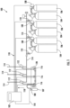
FIG. 1 is a schematic illustration of a typical fire suppression system that may incorporate embodiments of the present invention; -
FIG. 2A is top down schematic illustration of an exemplary selector valve assembly; -
FIG. 2B is a front elevation view of the selector valve assembly ofFIG. 2A ; -
FIG 2C is a side elevation view of the selector valve assembly ofFIG. 2A ; -
FIG. 2D is an exploded view of the components of the selector valve assembly ofFIG. 2A ; -
FIG. 3A is a bottom view of an exemplary valve positioner of a selector valve assembly; -
FIG. 3B is a side elevation view of a portion of a ball valve that connects to the valve positioner ofFIG. 3A ; -
FIG. 4A is a schematic illustration of an exemplary lockout valve assembly; -
FIG. 4B is a bottom view of a valve positioner of the lockout valve assembly ofFIG. 4A ; -
FIG. 4C is a top view of a portion of a ball valve of the lockout valve assembly ofFIG. 4A ; -
FIG. 4D is an enlarged illustration of a connection between a ball valve and a valve positioner of the lockout valve assembly ofFIG. 4A ; and -
FIG. 4E is an exploded view of the components of the lockout valve assembly ofFIG. 4A . - As shown and described herein, various features of embodiments of the invention will be presented. Various embodiments may have the same or similar features and thus the same or similar features may be labeled with the same reference numeral, but preceded by a different first number indicating the figure to which the feature is shown. Although similar reference numbers may be used in a generic sense, various embodiments will be described and various features may include changes, alterations, modifications, etc. as will be appreciated by those of skill in the art, whether explicitly described or otherwise would be appreciated by those of skill in the art.
- Referring to
FIG. 1 , a schematic illustration of a typicalfire suppression system 100 that may incorporate embodiments of the present invention is shown. Thefire suppression system 100 includes acontrol panel 102, one ormore agent cylinders 104, one ormore pilot cylinders 106, and associatedpiping 114. Thecontrol panel 102 connects to controlheads 108 that are attached to thepilot cylinders 106. The control heads 108 are configured to actuate thepilot cylinders 106, which actuate theagent cylinders 104 through flexible hoses or the like. - In operation, fire suppressing agent (e.g., material/fluid) flows through
check valves 110 to thepiping 114. The flow is directed by valves 112 (e.g., selector valves and/or lockout valves). Thevalves 112 are configured to open or close depending upon a signal received from thecontrol panel 102 throughwiring 118 to the control heads 108, asmall pilot cylinder 107, and/orsolenoids 116. Thesolenoids 116, as shown, are mounted to abackplate manifold 120. Thesmall pilot cylinder 107 is configured to supply pressure to thesolenoids 116, which open thevalves 112 and directs flow therethrough. - In accordance with embodiments of the present invention, the
valves 112 may be check valves, one-way valves, solenoid valves, selector valves, and/or lockout valves. Some of the valves may be pneumatically actuated and/or electronically actuated, as will be appreciated by those of skill in the art. The selector valves and/or lockout valves may include visual position indicators to indicate the state, position, or orientation of the valve. For example, such valves may include a rotatable ball valve that can be rotated between an open state and a closed state. Because the ball valve will be arranged within a flow line, a separate visual indicator on the external housing of the valve may be required to indicate the state/orientation of the valve to a technician. - Installation of these
valves 112 in a proper orientation is necessary to ensure the desired fire hazard protection from thecylinders 104 through thepiping 114. Additionally, during installation, maintenance, repairs, and/or replacement, a technician may be required to disassemblesuch valves 112. Typical selector and lockout valves allow for the valves to be disassembled by a field technician and reassembled in the incorrect orientation due to the symmetric nature of various components and features thereof. This incorrect installation could result in the visual position indicator of the valve indicating an open orientation while the valve is actually closed, or the visual position indicator indicates a closed orientation while the valve is actually open. These scenarios could lead to insufficient agent coverage during a discharge or failure to suppress the fire due to flow being prevented from reaching the correct location or flow being diverted to an incorrect location. Accordingly, ensuring proper installation and assembly of such valves is important and improvements to assembly features may be advantageous to ensure the valves operate as intended. - Referring to
FIGS. 2A-2D , schematic illustrations of avalve assembly 200 in accordance with an embodiment of the present invention are shown. In this illustrative configuration, thevalve assembly 200 is configured as a selector valve assembly. Thevalve assembly 200 may be used in a fire suppression system to control fluid flow through a pipe or other conduit, such as shown and described above. Thevalve assembly 200 includes avalve positioner 202 and aball valve assembly 204. In this embodiment, thevalve positioner 202 is arranged as a valve actuator. Thevalve positioner 202 may include various components for controlling operation of theball valve assembly 204, and specifically the orientation of theball valve assembly 204.FIGS. 2A-2C illustrate thevalve assembly 200 in an open state, with a full-bore 206 illustrated inFIG. 2C through theball valve assembly 204. Thevalve positioner 202 may include, for example, electronic and/or pneumatic components that are configured to control the orientation of the ball (e.g., open or closed) within theball valve assembly 204. - As shown in
FIGS. 2A-2C , and as noted above, thevalve assembly 200 is in the open state. However, when piping is connected to theball valve assembly 204, it is not possible to visually inspect the state of the ball within theball valve assembly 204. As such, thevalve positioner 202 includes aposition indicator 208. Theposition indicator 208 includes anindicator element 210 that is arranged to correspond to the position of the ball within theball valve assembly 204. Thevalve positioner 202 is coupled to theball valve assembly 204 by a mountingbracket 212 by one ormore fasteners 214. - Referring to
FIG. 2D , thevalve positioner 202 is shown separated from theball valve assembly 204. During installation, assembly, and/or maintenance, thevalve positioner 202 may be separated from theball valve assembly 204, and then must be reinstalled thereto. Because of the nature of the mountingbracket 212, different orientations are possible. That is, the mountingbracket 212 is substantially symmetric and thus can be installed in various different orientations between thevalve positioner 202 and theball valve assembly 204. The mountingbracket 212 may be integrally formed with or part of theball valve assembly 204. In other embodiments, the mountingbracket 212 may be integrally formed with or part of thevalve positioner 202. If the orientation of thevalve positioner 202 relative to theball valve assembly 204 is not properly set when connecting the two components, then theindicator element 210 of theindicator 208 may not accurately represent the orientation of the ball within theball valve assembly 204. - To prevent improper installation, the
valve assembly 200 includes apositioning pin 216 that is insertable into thevalve positioner 202 and the mountingbracket 212. In some embodiments, and as shown, thevalve positioner 202 may include apositioning aperture 218 for receiving thepositioning pin 216. Similarly, in some embodiments, the mountingbracket 212 may include apositioning aperture 220 for receiving thepositioning pin 216. Thepositioning apertures positioning pin 216, the twopositioning apertures positioning apertures valve positioner 202 and the ball valve assembly 204), then thevalve positioner 202 cannot be mounted to theball valve assembly 204. Stated another way, thepositioning pin 216 and thepositioning apertures valve positioner 202 to theball valve assembly 204. - Although shown as the
positioning pin 216 being separate from each of thevalve positioner 202 and the mounting bracket 212 (or ball valve assembly 204), such configuration is not to be limiting. For example, in some embodiments, the positioning pin may be integrally formed or part of the mountingbracket 212 or integrally formed or part of thevalve positioner 202. In such configurations, the other component (e.g., valve positioner or mounting plate) may include a positioning aperture for receiving the positioning pin. - Referring now to
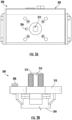
FIGS. 3A-3B , schematic illustrations of avalve assembly 300 in accordance with an embodiment of the present invention are shown. In this illustrative configuration, thevalve assembly 300 is configured as a selector valve assembly, similar to that shown and described with respect toFIGS. 2A-2D . Thevalve assembly 300 includes a valve positioner 302 (FIG. 3A ) and a ball valve assembly 304 (FIG. 3B ). Thevalve positioner 302 is arranged as a valve actuator and may include various components for controlling operation of theball valve assembly 304, and specifically the orientation of theball valve assembly 304. Thevalve positioner 302 may include, for example, electronic and/or pneumatic components that are configured to control the orientation of the ball (e.g., open or closed) within theball valve assembly 304. - In this configuration, the
valve positioner 302 includes apositioning aperture 306 for receiving apositioning pin 308. Thepositioning pin 308 of this embodiment is part of or installed to a mountingbracket 310. Thepositioning pin 308 andpositioning aperture 306 are configured to ensure proper installation of thevalve positioner 302 to the mountingbracket 310 of theball valve assembly 304. In this embodiment, an additional feature is provided for ensuring proper orientation between thevalve positioner 302 and theball valve assembly 304. For example, as shown inFIG. 3A , thevalve positioner 302 may include afemale aperture 312 and the mountingbracket 310 may include avalve shaft 314. Thevalve shaft 314 includes one or moreflat sides 316 and thus forms a substantially D-shape or double-D-shape to be received within thefemale aperture 312. This arrangement ensures specific orientation between the components. Further, theflat sides 316 may provide surface(s) upon which thevalve positioner 302 can act to rotate thevalve shaft 314. Thevalve shaft 314 may be operably coupled to the ball of theball valve assembly 304 such that rotation of thevalve shaft 314 causes rotation of the ball to open or close theball valve assembly 304. - Referring now to
FIGS. 4A-4E , schematic illustrations of avalve assembly 400 in accordance with an embodiment of the present invention are shown. In this illustrative configuration, thevalve assembly 400 is configured as a lockout valve assembly. Thevalve assembly 400 may be used in a fire suppression system to control fluid flow through a pipe or other conduit, such as shown and described above. Thevalve assembly 400 includes avalve positioner 402 and aball valve assembly 404. Thevalve positioner 402, in this embodiment, is arranged as a limit switch. In this configuration of a lockout valve assembly, thevalve positioner 402 is configured to be manually operated using ahandle 406. By rotating thehandle 406, a ball within theball valve assembly 404 may be rotated to open or close thevalve assembly 400. - The
valve positioner 402 includes a mountingbracket 408 and aposition indicator 410. Theposition indicator 410 includes anindicator element 412 that indicates a status or state of theball valve assembly 404. To provide such indication, aposition shaft 414 is coupled to theposition indicator 410 at one end and to thehandle 406 and/or theball valve assembly 404 at an opposite end. Accordingly, when the ball is rotated within the ball valve assembly 404 (e.g., by rotation of the handle 406) theposition shaft 414 will rotate and change the indication provided by theindicator element 412. - To mount the
valve positioner 402 to theball valve assembly 404, the mountingbracket 408 of thevalve positioner 402 is attached to avalve bracket 416 of theball valve assembly 404. In this illustrative configuration, the mountingbracket 408 includes afirst arm 418 and asecond arm 420 arranged in a substantially U-shape with theposition shaft 414 extending therebetween. Thefirst arm 418 includes one ormore fastener apertures 422 for receivingfasteners 424 therethrough. Thevalve bracket 416 of theball valve assembly 404 includes correspondingfastener apertures 426 to receive thefasteners 424 and connect the mountingbracket 408 to thevalve bracket 416. In this embodiment, there are twofastener apertures bracket 408 and thevalve bracket 416 and are arranged in relation to each other such that only one orientation of the mountingbracket 408 to thevalve bracket 416 is possible. - The
first arm 418 of the mountingbracket 408 also includes acutaway surface 428 that defines a cut-out in the geometry of the shape of thefirst arm 418. The cutaway in thefirst arm 418 is shaped to allow operation of thehandle 406 and limit the rotation thereof to a substantially 90° rotation. That is, thefirst arm 418 and thecutaway surface 428 are configured to limit the rotation of thehandle 406. Additionally, thevalve bracket 416 includesrecesses 430 for receiving a portion of thehandle 406 to lock the position of thehandle 406 in place relative to thevalve bracket 416. Thehandle 406 of theball valve 404 is configured to operably couple to avalve shaft 432 that allows for manual rotation of the ball of theball valve assembly 404. Thevalve shaft 432 includes aslot 434 on the visible end thereof that is configured to receive atab 436 of theposition shaft 414. As such, when thevalve shaft 432 is rotated by actuation of thehandle 406, theposition shaft 414 will also rotate causing a change of state of theindicator element 412 of theposition indicator 410. Thevalve shaft 432 may have a D-shape or double-D-shape, similar to that shown and described above with respect toFIGS. 3A-3B - Because of the inclusion of the
cutaway surface 428, therecesses 430, and thefastener apertures bracket 408 and thevalve bracket 416, thefasteners 424 may operate similar to the positioning pin shown and described above. As such, in some embodiments, thefasteners 424 illustratively shown as discrete or separate fasteners, could be incorporated into one of thevalve bracket 416 or the mountingbracket 408, with the other component having receiving holes or apertures for receiving the positioning pins and secure the mounting bracket to the valve bracket. - In accordance with embodiments of the present invention valve assemblies are configured to include a positioning pin and/or D-shaped shaft as an added safety feature. The combination of the positioning pin and the D-shaped shaft prevents the valve assemblies from being assembled or installed in an incorrect orientation. As shown above, this may be applied to both selector valves (e.g.,
FIGS. 2A-2D ,3A-3B ) and lockout valves (e.g.,FIGS. 4A-4E ). In the case of selector valves, and in accordance with some non-limiting embodiments, a positioning pin and Double-D shaft may be added as safety features thereto. The combination of the positioning pin and the Double-D shaft prevents the selector valve body and actuator from being assembled or installed in an incorrect orientation. In the case of lockout valves, such configurations, in accordance with some embodiments of the present invention, and without limitation, may include a positioning pin, a Double-D valve shaft, and a handle locking tool. The combination of the bracket holes in the limit switch and valve body, the handle locking tool, and the Double-D shaft constrains the handle to a 90-degree rotation and prevents the valve and limit switch assemblies from being installed in an incorrect orientation. - Advantageously, embodiments described herein provide for improved valve assemblies for fire suppression systems that includes mistake-proof assembly and installation features. The mistake-proof features ensure that when a technician installs and/or performs repairs or maintenance upon a valve of the fire suppression system the valve will be reassembled correctly and thus avoid issues related to improper installation of such valves and/or use of such valves in fire suppression systems.
- The use of the terms "a", "an", "the", and similar references in the context of description (especially in the context of the following claims) are to be construed to cover both the singular and the plural, unless otherwise indicated herein or specifically contradicted by context. The modifier "about" or "substantially" used in connection with a quantity is inclusive of the stated value and has the meaning dictated by the context (e.g., it includes the degree of error associated with measurement of the particular quantity). All ranges disclosed herein are inclusive of the endpoints, and the endpoints are independently combinable with each other.
- While the present invention has been described in detail in connection with only a limited number of embodiments, it should be readily understood that the present invention is not limited to such disclosed embodiments. Rather, the present invention can be modified to incorporate any number of variations, alterations, substitutions, combinations, sub-combinations, or equivalent arrangements not heretofore described, but which are commensurate with the scope of the present invention. Additionally, while various embodiments of the present invention have been described, it is to be understood that aspects of the present invention may include only some of the described embodiments.
- Accordingly, the present invention is not to be seen as limited by the foregoing description but is only limited by the scope of the appended claims.
- The following clauses set out features of the invention which may not presently be claimed in this application, but which may form the basis for future amendment or a divisional application.
- 1. A valve assembly comprising:
- a valve positioner;
- a ball valve assembly configured to be actuated by the valve positioner between an open state and a closed state;
- an indicator configured to provide visual indication of the state of the ball valve assembly; and
- a positioning pin configured between the valve positioner and the ball valve assembly, the positioning pin arranged to prevent installation of the valve positioner to the ball valve assembly in all but one orientation and to ensure installation in only one orientation.
- 2. The valve assembly of clause 1, wherein the positioning pin is configured to align the valve positioner to the ball valve assembly in a correct orientation for normal operation.
- 3. The valve assembly of clause 1, wherein the valve positioner is part of a selector valve assembly.
- 4. The valve assembly of clause 3, further comprising a valve shaft operably connecting the valve positioner to the ball valve assembly.
- 5. The valve assembly of clause 4, wherein the valve shaft is part of the ball valve assembly.
- 6. The valve assembly of clause 4, wherein the valve shaft has a double D-shape in cross-section.
- 7. The valve assembly of clause 4, wherein the valve shaft is configured to threadedly connect to a female aperture of the valve positioner.
- 8. The valve assembly of clause 3, wherein the ball valve assembly comprises a mounting bracket and one or more fasteners configured to secure the valve positioner to the mounting bracket.
- 9. The valve assembly of clause 1, wherein the valve positioner is part of a lockout valve assembly.
- 10. The valve assembly of clause 9, wherein the ball valve assembly comprises a handle for manual actuation thereof.
- 11. The valve assembly of clause 10, wherein the handle is configured to rotate only 90 degrees between the open state and the closed state of the ball valve assembly.
- 12. The valve assembly of clause 9, wherein the valve positioner comprises a mounting bracket and the ball valve assembly comprises a valve bracket, wherein the mounting bracket is configured to be installed onto the valve bracket in only the one orientation.
- 13. The valve assembly of clause 12, wherein the positioning pin is arranged to position the valve bracket relative to the mounting bracket in the one orientation.
- 14. The valve assembly of clause 12, wherein the mounting bracket comprises a first arm and a second arm arranged in a U-shape.
- 15. The valve assembly of clause 14, wherein the first arm comprises a cutaway surface to restrict rotation of a handle to a 90 degree rotation.
- 16. The valve assembly of clause 12, wherein the valve bracket comprises a first recess and a second recess, wherein a handle is rotatable between the first recess and the second recess to securely position the ball valve assembly in the first state and the second state, respectively.
- 17. The valve assembly of clause 9, wherein the valve positioner comprises a position shaft operably coupled to the position indicator at one end and a valve shaft of the ball valve assembly at an opposite end, wherein rotation of the valve shaft causes rotation of the position shaft and change a state of the position indicator.
- 18. The valve assembly of clause 1, wherein the valve positioner is part of a limit switch assembly.
- 19. The valve assembly of clause 18, wherein the valve positioner comprises a position shaft operably coupled to the position indicator at one end and a valve shaft of the ball valve assembly at an opposite end, wherein rotation of the valve shaft causes rotation of the position shaft and change a state of the position indicator.
- 20. The valve assembly of clause 18, wherein the ball valve assembly comprises a handle for manual actuation thereof.
Claims (15)
- A valve assembly comprising:a valve positioner (202; 302; 402);a ball valve assembly (204; 304; 404) configured to be actuated by the valve positioner between an open state and a closed state;an indicator (208; 410) configured to provide visual indication of the state of the ball valve assembly; anda positioning pin (216; 308; 424) configured between the valve positioner (202; 302; 402) and the ball valve assembly (204; 304; 404), the positioning pin arranged to prevent installation of the valve positioner to the ball valve assembly in all but one orientation and to ensure installation in only one orientation.
- The valve assembly of claim 1, wherein the positioning pin (216; 308; 424) is configured to align the valve positioner (202; 302; 402) to the ball valve assembly (204; 304; 404) in a correct orientation for normal operation.
- The valve assembly of claim 1 or 2, wherein the valve positioner (202; 302) is part of a selector valve assembly (200; 300).
- The valve assembly of any preceding claim, further comprising a valve shaft (314) operably connecting the valve positioner (302) to the ball valve assembly (304),
and optionally wherein:the valve shaft (314) is part of the ball valve assembly (304),and/or the valve shaft (314) has a double D-shape in cross-section. - The valve assembly of claim 4, wherein the valve shaft (314) is configured to threadedly connect to a female aperture (312) of the valve positioner (302).
- The valve assembly of any preceding claim, wherein the ball valve assembly (204) comprises a mounting bracket (212) and one or more fasteners (214) configured to secure the valve positioner (202) to the mounting bracket.
- The valve assembly of claim 1 or 2, wherein the valve positioner (402) is part of a lockout valve assembly (400).
- The valve assembly of claim 7, wherein the ball valve assembly (404) comprises a handle (406) for manual actuation thereof.
- The valve assembly of claim 8, wherein the handle (406) is configured to rotate only 90 degrees between the open state and the closed state of the ball valve assembly (404).
- The valve assembly of any of claims 7 to 9, wherein the valve positioner (402) comprises a mounting bracket (408) and the ball valve assembly (404) comprises a valve bracket (416), wherein the mounting bracket (408) is configured to be installed onto the valve bracket (416) in only the one orientation.
- The valve assembly of claim 10, wherein the positioning pin (424) is arranged to position the valve bracket (416) relative to the mounting bracket (408) in the one orientation.
- The valve assembly of claim 10 or 11, wherein the mounting bracket (408) comprises a first arm (418) and a second arm (420) arranged in a U-shape, optionally wherein the first arm (418) comprises a cutaway surface (428) to restrict rotation of a handle (406) to a 90 degree rotation.
- The valve assembly of any of claims 10 to 12, wherein the valve bracket (416) comprises a first recess (430) and a second recess (430), wherein a handle (406) is rotatable between the first recess and the second recess to securely position the ball valve assembly (404) in the first state and the second state, respectively.
- The valve assembly of any of claims 7 to 13, wherein the valve positioner (402) comprises a position shaft (414) operably coupled to the position indicator (410) at one end and a valve shaft (432) of the ball valve assembly (404) at an opposite end, wherein rotation of the valve shaft (432) causes rotation of the position shaft (414) and changes a state of the position indicator (410).
- The valve assembly of any preceding claim, wherein the valve positioner (202; 302; 402) is part of a limit switch assembly.
Applications Claiming Priority (1)
| Application Number | Priority Date | Filing Date | Title |
|---|---|---|---|
| US202263333233P | 2022-04-21 | 2022-04-21 |
Publications (1)
| Publication Number | Publication Date |
|---|---|
| EP4265943A1 true EP4265943A1 (en) | 2023-10-25 |
Family
ID=86142911
Family Applications (1)
| Application Number | Title | Priority Date | Filing Date |
|---|---|---|---|
| EP23169284.9A Pending EP4265943A1 (en) | 2022-04-21 | 2023-04-21 | Selector and lockout valve mistake-proof design features |
Country Status (3)
| Country | Link |
|---|---|
| US (1) | US12429139B2 (en) |
| EP (1) | EP4265943A1 (en) |
| CN (1) | CN116928433A (en) |
Cited By (1)
| Publication number | Priority date | Publication date | Assignee | Title |
|---|---|---|---|---|
| RU230530U1 (en) * | 2024-07-22 | 2024-12-09 | Закрытое акционерное общество "Производственное объединение "Спецавтоматика" | VALVE WITH SHUT-OFF VALVE POSITION CONTROL |
Families Citing this family (1)
| Publication number | Priority date | Publication date | Assignee | Title |
|---|---|---|---|---|
| GB2631678A (en) * | 2023-05-16 | 2025-01-15 | Kinetrol Ltd | Adaptor for mechanical device |
Citations (9)
| Publication number | Priority date | Publication date | Assignee | Title |
|---|---|---|---|---|
| US4719939A (en) * | 1987-06-10 | 1988-01-19 | Conbraco Industries, Inc. | Apparatus for coupling a valve and rotary actuator |
| US5954088A (en) * | 1998-07-17 | 1999-09-21 | Transworld Steel Enterprise Corp. | Ball valve adapted to couple with an output drive shaft of a valve control device |
| EP1672261A1 (en) * | 2004-12-17 | 2006-06-21 | Invensys Building Systems, Inc. | Removable interconnection of an actuator to a valve body |
| WO2006118361A1 (en) * | 2005-05-04 | 2006-11-09 | Alco Corporation | Motorized diverting valve |
| EP1418373B1 (en) * | 2002-11-08 | 2007-05-23 | Caleffi S.p.A. | Valve with removable actuator |
| US9010722B2 (en) * | 2011-02-01 | 2015-04-21 | Hayward Industries, Inc. | Valve switchbox |
| US20150285311A1 (en) * | 2014-04-02 | 2015-10-08 | Belimo Holding Ag | Connection joint |
| US10591080B2 (en) * | 2015-05-27 | 2020-03-17 | Flo Technologies, Inc. | Retrofit motorized actuator for remote fluid control |
| US10962993B2 (en) * | 2013-02-18 | 2021-03-30 | Flo Technologies, Inc. | Manual control for actuated fluid monitoring and control device |
Family Cites Families (12)
| Publication number | Priority date | Publication date | Assignee | Title |
|---|---|---|---|---|
| JPS6093098U (en) * | 1983-12-01 | 1985-06-25 | 日本酸素株式会社 | Remote opening/closing equipment for container valves |
| US6302132B1 (en) * | 2000-04-27 | 2001-10-16 | Nordstrom Valves, Inc | Valve assembly including gearbox |
| US6206023B1 (en) * | 2000-04-27 | 2001-03-27 | Nordstrom Valves, Inc. | Ball valve including seat retainer securing means and method for forming the same |
| US6676109B2 (en) * | 2001-05-22 | 2004-01-13 | Kitz Corporation | Rotary valve |
| US6959909B2 (en) * | 2004-01-26 | 2005-11-01 | Victaulic Company Of America | Actuating handle assembly |
| KR101290931B1 (en) * | 2006-03-20 | 2013-07-29 | 아사히 유키자이 고교 가부시키가이샤 | Rotary valve |
| GB0910082D0 (en) * | 2009-06-11 | 2009-07-22 | Norgren Ltd C A | Two-part valve |
| US20140264111A1 (en) * | 2013-03-15 | 2014-09-18 | Designport, Inc. | Automatic valve actuator systems |
| US10384317B2 (en) * | 2016-06-07 | 2019-08-20 | Valve Innovations, Llc | Kit for mounting a valve position indicator to a valve |
| US20190192892A1 (en) * | 2017-12-22 | 2019-06-27 | Carrier Corporation | Inert Gas Remote Driver Liquid Fire Suppression Systems |
| CN208487259U (en) * | 2018-02-08 | 2019-02-12 | 成霖企业股份有限公司 | Cover fixing structure of valve assembly |
| WO2020223139A1 (en) * | 2019-05-02 | 2020-11-05 | Swagelok Company | Nut locking coupling for actuated valve |
-
2023
- 2023-03-14 US US18/183,657 patent/US12429139B2/en active Active
- 2023-04-21 CN CN202310433858.6A patent/CN116928433A/en active Pending
- 2023-04-21 EP EP23169284.9A patent/EP4265943A1/en active Pending
Patent Citations (9)
| Publication number | Priority date | Publication date | Assignee | Title |
|---|---|---|---|---|
| US4719939A (en) * | 1987-06-10 | 1988-01-19 | Conbraco Industries, Inc. | Apparatus for coupling a valve and rotary actuator |
| US5954088A (en) * | 1998-07-17 | 1999-09-21 | Transworld Steel Enterprise Corp. | Ball valve adapted to couple with an output drive shaft of a valve control device |
| EP1418373B1 (en) * | 2002-11-08 | 2007-05-23 | Caleffi S.p.A. | Valve with removable actuator |
| EP1672261A1 (en) * | 2004-12-17 | 2006-06-21 | Invensys Building Systems, Inc. | Removable interconnection of an actuator to a valve body |
| WO2006118361A1 (en) * | 2005-05-04 | 2006-11-09 | Alco Corporation | Motorized diverting valve |
| US9010722B2 (en) * | 2011-02-01 | 2015-04-21 | Hayward Industries, Inc. | Valve switchbox |
| US10962993B2 (en) * | 2013-02-18 | 2021-03-30 | Flo Technologies, Inc. | Manual control for actuated fluid monitoring and control device |
| US20150285311A1 (en) * | 2014-04-02 | 2015-10-08 | Belimo Holding Ag | Connection joint |
| US10591080B2 (en) * | 2015-05-27 | 2020-03-17 | Flo Technologies, Inc. | Retrofit motorized actuator for remote fluid control |
Cited By (1)
| Publication number | Priority date | Publication date | Assignee | Title |
|---|---|---|---|---|
| RU230530U1 (en) * | 2024-07-22 | 2024-12-09 | Закрытое акционерное общество "Производственное объединение "Спецавтоматика" | VALVE WITH SHUT-OFF VALVE POSITION CONTROL |
Also Published As
| Publication number | Publication date |
|---|---|
| CN116928433A (en) | 2023-10-24 |
| US12429139B2 (en) | 2025-09-30 |
| US20230341059A1 (en) | 2023-10-26 |
Similar Documents
| Publication | Publication Date | Title |
|---|---|---|
| JP3280003B2 (en) | Supply / exhaust device for solenoid valve assembly | |
| US9010722B2 (en) | Valve switchbox | |
| CN100422613C (en) | Elastic return operator | |
| US12429139B2 (en) | Selector and lockout valve mistake-proof design features | |
| JP5710692B2 (en) | Expandable gas or liquid distribution system | |
| US6240941B1 (en) | Modular, interconnectable valve | |
| US5482251A (en) | Stem extension for quarter-turn valves | |
| US6349424B1 (en) | Rinse fluid valve for a vacuum toilet | |
| EP2232082A1 (en) | Block and bleed valve assembly | |
| WO2008121408A1 (en) | Quick change check valve system | |
| EP2414715A1 (en) | Manual valve operators having a lockout device | |
| EP2000730B1 (en) | A pipeline breakaway coupling | |
| KR102873538B1 (en) | Ball Valve Handle Locking Device | |
| JP7503346B2 (en) | valve | |
| US6681791B1 (en) | Manifold valve position indicator and operator alerting system | |
| US6349425B1 (en) | Valve set for a vacuum toilet | |
| EP3311048A1 (en) | A ball valve assembly | |
| US12281718B2 (en) | Valve-actuator interface to simplify valve repair and maintenance | |
| US11796079B2 (en) | Valve assembly | |
| KR20230115742A (en) | Valve open/close status confirmation device | |
| CN222416117U (en) | A liquid flow control valve | |
| EP2556280B1 (en) | Actuator adapter plate | |
| EP4571159A1 (en) | A valve assembly with a valve housing and an actuator housing | |
| CN116324242A (en) | adapter assembly | |
| US8215332B1 (en) | Zone indicator and vacuum breaker combination |
Legal Events
| Date | Code | Title | Description |
|---|---|---|---|
| STAA | Information on the status of an ep patent application or granted ep patent |
Free format text: STATUS: THE APPLICATION HAS BEEN PUBLISHED |
|
| PUAI | Public reference made under article 153(3) epc to a published international application that has entered the european phase |
Free format text: ORIGINAL CODE: 0009012 |
|
| AK | Designated contracting states |
Kind code of ref document: A1 Designated state(s): AL AT BE BG CH CY CZ DE DK EE ES FI FR GB GR HR HU IE IS IT LI LT LU LV MC ME MK MT NL NO PL PT RO RS SE SI SK SM TR |
|
| STAA | Information on the status of an ep patent application or granted ep patent |
Free format text: STATUS: REQUEST FOR EXAMINATION WAS MADE |
|
| 17P | Request for examination filed |
Effective date: 20240425 |
|
| RBV | Designated contracting states (corrected) |
Designated state(s): AL AT BE BG CH CY CZ DE DK EE ES FI FR GB GR HR HU IE IS IT LI LT LU LV MC ME MK MT NL NO PL PT RO RS SE SI SK SM TR |
|
| RAP1 | Party data changed (applicant data changed or rights of an application transferred) |
Owner name: KIDDE-FENWAL, LLC |
|
| STAA | Information on the status of an ep patent application or granted ep patent |
Free format text: STATUS: EXAMINATION IS IN PROGRESS |
|
| 17Q | First examination report despatched |
Effective date: 20250210 |
|
| P01 | Opt-out of the competence of the unified patent court (upc) registered |
Free format text: CASE NUMBER: APP_30606/2025 Effective date: 20250626 |