EP4265901A1 - Engine and straddled vehicle including same - Google Patents
Engine and straddled vehicle including same Download PDFInfo
- Publication number
- EP4265901A1 EP4265901A1 EP23168575.1A EP23168575A EP4265901A1 EP 4265901 A1 EP4265901 A1 EP 4265901A1 EP 23168575 A EP23168575 A EP 23168575A EP 4265901 A1 EP4265901 A1 EP 4265901A1
- Authority
- EP
- European Patent Office
- Prior art keywords
- crankshaft
- crankcase
- engine
- damper
- damper mass
- Prior art date
- Legal status (The legal status is an assumption and is not a legal conclusion. Google has not performed a legal analysis and makes no representation as to the accuracy of the status listed.)
- Granted
Links
Images



Classifications
-
- F—MECHANICAL ENGINEERING; LIGHTING; HEATING; WEAPONS; BLASTING
- F16—ENGINEERING ELEMENTS AND UNITS; GENERAL MEASURES FOR PRODUCING AND MAINTAINING EFFECTIVE FUNCTIONING OF MACHINES OR INSTALLATIONS; THERMAL INSULATION IN GENERAL
- F16F—SPRINGS; SHOCK-ABSORBERS; MEANS FOR DAMPING VIBRATION
- F16F3/00—Spring units consisting of several springs, e.g. for obtaining a desired spring characteristic
- F16F3/08—Spring units consisting of several springs, e.g. for obtaining a desired spring characteristic with springs made of a material having high internal friction, e.g. rubber
- F16F3/10—Spring units consisting of several springs, e.g. for obtaining a desired spring characteristic with springs made of a material having high internal friction, e.g. rubber combined with springs made of steel or other material having low internal friction
-
- F—MECHANICAL ENGINEERING; LIGHTING; HEATING; WEAPONS; BLASTING
- F02—COMBUSTION ENGINES; HOT-GAS OR COMBUSTION-PRODUCT ENGINE PLANTS
- F02F—CYLINDERS, PISTONS OR CASINGS, FOR COMBUSTION ENGINES; ARRANGEMENTS OF SEALINGS IN COMBUSTION ENGINES
- F02F7/00—Casings, e.g. crankcases
- F02F7/0065—Shape of casings for other machine parts and purposes, e.g. utilisation purposes, safety
- F02F7/0068—Adaptations for other accessories
-
- F—MECHANICAL ENGINEERING; LIGHTING; HEATING; WEAPONS; BLASTING
- F02—COMBUSTION ENGINES; HOT-GAS OR COMBUSTION-PRODUCT ENGINE PLANTS
- F02B—INTERNAL-COMBUSTION PISTON ENGINES; COMBUSTION ENGINES IN GENERAL
- F02B77/00—Component parts, details or accessories, not otherwise provided for
- F02B77/11—Thermal or acoustic insulation
- F02B77/13—Acoustic insulation
-
- F—MECHANICAL ENGINEERING; LIGHTING; HEATING; WEAPONS; BLASTING
- F02—COMBUSTION ENGINES; HOT-GAS OR COMBUSTION-PRODUCT ENGINE PLANTS
- F02F—CYLINDERS, PISTONS OR CASINGS, FOR COMBUSTION ENGINES; ARRANGEMENTS OF SEALINGS IN COMBUSTION ENGINES
- F02F7/00—Casings, e.g. crankcases
- F02F7/0021—Construction
-
- F—MECHANICAL ENGINEERING; LIGHTING; HEATING; WEAPONS; BLASTING
- F02—COMBUSTION ENGINES; HOT-GAS OR COMBUSTION-PRODUCT ENGINE PLANTS
- F02F—CYLINDERS, PISTONS OR CASINGS, FOR COMBUSTION ENGINES; ARRANGEMENTS OF SEALINGS IN COMBUSTION ENGINES
- F02F7/00—Casings, e.g. crankcases
- F02F7/0043—Arrangements of mechanical drive elements
-
- F—MECHANICAL ENGINEERING; LIGHTING; HEATING; WEAPONS; BLASTING
- F02—COMBUSTION ENGINES; HOT-GAS OR COMBUSTION-PRODUCT ENGINE PLANTS
- F02F—CYLINDERS, PISTONS OR CASINGS, FOR COMBUSTION ENGINES; ARRANGEMENTS OF SEALINGS IN COMBUSTION ENGINES
- F02F7/00—Casings, e.g. crankcases
- F02F7/0043—Arrangements of mechanical drive elements
- F02F7/0053—Crankshaft bearings fitted in the crankcase
-
- F—MECHANICAL ENGINEERING; LIGHTING; HEATING; WEAPONS; BLASTING
- F02—COMBUSTION ENGINES; HOT-GAS OR COMBUSTION-PRODUCT ENGINE PLANTS
- F02F—CYLINDERS, PISTONS OR CASINGS, FOR COMBUSTION ENGINES; ARRANGEMENTS OF SEALINGS IN COMBUSTION ENGINES
- F02F7/00—Casings, e.g. crankcases
- F02F7/006—Camshaft or pushrod housings
-
- F—MECHANICAL ENGINEERING; LIGHTING; HEATING; WEAPONS; BLASTING
- F16—ENGINEERING ELEMENTS AND UNITS; GENERAL MEASURES FOR PRODUCING AND MAINTAINING EFFECTIVE FUNCTIONING OF MACHINES OR INSTALLATIONS; THERMAL INSULATION IN GENERAL
- F16F—SPRINGS; SHOCK-ABSORBERS; MEANS FOR DAMPING VIBRATION
- F16F7/00—Vibration-dampers; Shock-absorbers
- F16F7/10—Vibration-dampers; Shock-absorbers using inertia effect
- F16F7/104—Vibration-dampers; Shock-absorbers using inertia effect the inertia member being resiliently mounted
- F16F7/116—Vibration-dampers; Shock-absorbers using inertia effect the inertia member being resiliently mounted on metal springs
-
- F—MECHANICAL ENGINEERING; LIGHTING; HEATING; WEAPONS; BLASTING
- F16—ENGINEERING ELEMENTS AND UNITS; GENERAL MEASURES FOR PRODUCING AND MAINTAINING EFFECTIVE FUNCTIONING OF MACHINES OR INSTALLATIONS; THERMAL INSULATION IN GENERAL
- F16F—SPRINGS; SHOCK-ABSORBERS; MEANS FOR DAMPING VIBRATION
- F16F2230/00—Purpose; Design features
- F16F2230/0052—Physically guiding or influencing
- F16F2230/007—Physically guiding or influencing with, or used as an end stop or buffer; Limiting excessive axial separation
-
- F—MECHANICAL ENGINEERING; LIGHTING; HEATING; WEAPONS; BLASTING
- F16—ENGINEERING ELEMENTS AND UNITS; GENERAL MEASURES FOR PRODUCING AND MAINTAINING EFFECTIVE FUNCTIONING OF MACHINES OR INSTALLATIONS; THERMAL INSULATION IN GENERAL
- F16F—SPRINGS; SHOCK-ABSORBERS; MEANS FOR DAMPING VIBRATION
- F16F2238/00—Type of springs or dampers
- F16F2238/02—Springs
- F16F2238/022—Springs leaf-like, e.g. of thin, planar-like metal
Definitions
- the present invention relates to an engine and a straddled vehicle including the engine.
- JP 2002-005235 A proposes a structure for preventing vibration of a crankshaft.
- a dynamic damper is provided at the end portion of the crankshaft.
- a centrifugal oil strainer is attached to one end portion of the crankshaft extending in one direction.
- the dynamic damper is attached to the oil strainer via a bowl-shaped attachment plate.
- the dynamic damper is constituted by an annular elastic object and an annular damper weight, and is configured to be unitized with the attachment plate by baking of the elastic object on the attachment plate.
- the antivibration performance of the damper weight is set in consideration of the fact that the rigidity of the crankcase varies depending on a direction.
- the antivibration performance of the damper weight needs to be set in consideration of not only the ratio of the mass of a damper weight to the mass of a crankshaft and the composition of the elastic object but also the arrangement of the peripheral members of the damper weight, the allowable size of the damper weight, and the like. Therefore, it is not easy to provide the dynamic damper at the crankshaft rotating at high speed and appropriately set the antivibration performance. Therefore, it is not easy to fabricate the above-mentioned engine.
- vibration that is reduced by the dynamic damper is transmitted from the crankshaft to the crankcase.
- the rigidity of the crankcase is defined based on the shape and size of the crankcase. That is, the rigidity of a plurality of types of crankcases respectively provided in a plurality of types of engines do not necessarily have a common directional feature. Therefore, depending on the configuration of the crankcase, the vibration reduced by the dynamic damper may be transmitted to the crankcase, and thus excessive noise may be generated from a power unit or the like including the crankcase.
- An object of the present invention is to provide an engine which can be easily fabricated and can reduce generation of noise, and a straddled vehicle including the engine. According to the present invention said object is solved by an engine having the features of independent claim 1. Preferred embodiments are laid down in the dependent claims.
- An engine includes a crankshaft, a crankcase accommodating the crankshaft, and a dynamic damper provided at the crankcase, wherein the dynamic damper includes a damper mass, and a supporter that has an elastic object, and vibratably supports the damper mass at the crankcase such that the damper mass is vibratable by the elastic object on one straight line that is orthogonal to a center axis of the crankshaft and parallel to a direction of bending vibration generated in the crankshaft.
- the dynamic damper is provided in the crankcase.
- the degree of freedom in design and attachment of the dynamic damper is improved, and the engine can be easily fabricated.
- the damper mass of the dynamic damper vibrates on the one straight line parallel to the direction of the bending vibration of the crankshaft.
- the vibration transmitted to the peripheral members of the crankshaft due to the bending vibration of the crankshaft is efficiently absorbed by the dynamic damper. Therefore, at least part of vibration that causes noise generated from the power unit including the crankcase and its peripheral members is efficiently absorbed by the dynamic damper.
- the engine which is easily fabricated and in which generation of noise is reduced is realized.
- the supporter may vibratably support the damper mass at the crankcase such that an elastic force of the elastic object is exerted on the damper mass on the one straight line, while the supporter restricts a vibration direction of the damper mass such that the damper mass is not vibratable on another straight line that intersects with the one straight line.
- the damper mass of the dynamic damper vibrates only on the one straight line parallel to the direction of the bending vibration of the crankshaft.
- vibration that causes noise is more efficiently absorbed.
- the supporter may have a first leaf spring portion and a second leaf spring portion as the elastic objects, the first leaf spring portion and the second leaf spring portion may be provided at the crankcase to be arranged at a distance from each other in a direction parallel to the one straight line, and each of the first leaf spring portion and the second leaf spring portion may be provided to connect the crankcase and the damper mass to each other.
- the leaf spring has a thickness that is smaller than that of other elastic members such as a coil spring and a rubber member. Therefore, with the above-mentioned configuration, it is possible to restrict the vibration direction of the damper mass with respect to the crankcase without requiring an excessive installation space.
- Each of the first leaf spring portion and the second leaf spring portion may be formed in a flat plate shape having one surface and another surface that face in mutually opposite directions, and may be provided at the crankcase such that the one surface and the another surface are orthogonal to the one straight line.
- each of the first leaf spring portion and the second leaf spring portion is bent in a plane orthogonal to the center axis of the crankshaft, so that the damper mass vibrates on the one straight line with a simple configuration.
- the crankcase may have an attachment surface that is orthogonal to a center axis of the crankshaft, the supporter may have a first portion and a second portion attached to the attachment surface, and the crankshaft may be located in a region between a portion to which the first portion of the supporter is attached in the attachment surface and a portion to which the second portion of the supporter is attached in the attachment surface when being viewed in a direction extending along the center axis of the crankshaft.
- the damper mass can be arranged in the vicinity of the crankshaft when being viewed in the direction extending along the center axis of the crankshaft.
- the damper mass can be arranged to overlap with the crankshaft.
- the dynamic damper may further include a rubber member provided between the attachment surface of the crankcase and the damper mass.
- the rubber member absorbs the vibration of the damper mass caused by the elastic forces of the first leaf spring portion and the second leaf spring portion. Thus, generation of noise due to strong vibration of the damper mass is suppressed.
- the engine may further include a bearing that supports the crankshaft in the crankcase, wherein the crankcase may have a fixing portion to which the bearing is fixed, and the dynamic damper may be attached to the fixing portion.
- the fixing portion of the crankcase supports the crankshaft via the bearing. Therefore, vibration is easily transmitted from the crankshaft to the fixing portion.
- the dynamic damper is attached to the fixing portion, large part of vibration transmitted from the crankshaft to the crankcase is efficiently absorbed by the dynamic damper.
- a straddled vehicle includes a main body having a drive wheel, and the above-mentioned engine that generates motive power for rotating the drive wheel.
- the straddled vehicle includes the above-mentioned engine. This facilitates fabrication of the straddled vehicle. Further, at least part of vibration that causes noise generated from the power unit including the crankcase and its peripheral members is efficiently absorbed by the dynamic damper. As a result, the straddled vehicle which is easily fabricated and in which generation of noise is reduced is realized.
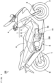
- Fig. 1 is a right side view of a motorcycle according to the preferred embodiment.
- the motorcycle 100 of Fig. 1 includes a metallic body frame 1.
- the body frame 1 includes a head pipe 11 and a plurality of frame members.
- two frame members 12, 13 of the plurality of frame members are shown.
- the head pipe 11 is located in a front portion of the vehicle.
- the frame members 12, 13 are provided so as to extend rearwardly of the vehicle from the head pipe 11.
- a front fork 2 is provided at the head pipe 11 to be rotatable about the center axis of the head pipe 11.
- a front wheel 3 is rotatably supported at the lower end portion of the front fork 2.
- a handle 4 is provided at the upper end portion of the front fork 2.
- the body frame 1 supports a plurality of constituent elements of the motorcycle 100 including a seat 5, a power unit 6 and a rear arm 7.
- the seat 5 is provided in a substantially central upper portion of the motorcycle 100 in a front-and-rear direction.
- the power unit 6 includes an engine 6A and is provided at a substantially central lower portion of the motorcycle 100 in the front-and-rear direction.
- a side cover made of resin is provided so as to interpose the front half portion (the portion of the engine 6A) of the power unit 6 in a left-and-right direction of the motorcycle 100.
- a rear arm 7 is provided to extend rearwardly from a position in the vicinity of the rear end portion of the power unit 6.
- the rear arm 7 is supported at the body frame 1 with use of a pivot shaft (not shown).
- a rear wheel 8 is rotatably supported at the rear end portion of the rear arm 7. The rear wheel 8 is rotated as a drive wheel by the motive power generated by the engine 6A of the power unit 6.
- noise may be generated from the motorcycle 100 as the crankshaft 61 included in the engine 6A rotates.
- a dynamic damper 200 is provided as the configuration for reducing noise generated during an operation of the engine. The mechanism of generation of noise and the specific configuration and function of the dynamic damper 200 will be described.
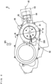
- Fig. 2 is a side view of the power unit 6 of Fig. 1 as viewed from a position farther rightward than the motorcycle.
- the power unit 6 includes the engine 6A.
- the engine 6A has a cylinder head 63.
- the cylinder head 63 has the configuration in which two cylinders are arranged in the left-and-right direction of the motorcycle 100.
- the outer shape of the cylinder head 63 is schematically shown by the one-dot and dash lines.
- the power unit 6 includes a crankcase 62.
- the crankcase 62 according to the present embodiment accommodates the crankshaft 61.
- the crankshaft 61 extends in the left-and-right direction of the motorcycle 100 in the crankcase 62.
- Two pistons 64 are connected to the crankshaft 61 via two connecting rods 65, respectively.
- the two pistons 64 of the crankshaft 61 are respectively provided so as to be reciprocatable in the two cylinders of the cylinder head 63.
- a right piston 64 and a right connecting rod 65 located in the cylinder head 63 are indicated by the solid lines.
- the virtual straight line passing through the center axis of a right cylinder of the cylinder head 63 is indicated by the two-dots and dash line as a cylinder axis AS.
- FIG. 3 is a diagram for explaining the bending vibration generated in the crankshaft 61 of Fig. 2 .
- the outer shape of the power unit 6 as viewed from a position above the power unit 6 in the direction indicated by the outlined arrow VP1 of Fig. 2 is shown.
- the crankshaft 61, the two pistons 64 and the two connecting rods 65 provided in the power unit 6 are indicated by the solid lines. Further, in Fig.
- crank axis 61c the virtual straight line passing through the center axis of the crankshaft 61 is indicated by the two-dots and dash line as a crank axis 61c.
- the direction of the outlined arrow VP1 of Fig. 2 is the direction orthogonal to the cylinder axis AS when the power unit 6 is viewed in the direction extending along the center axis (crank axis 61c) of the crankshaft 61.
- the crankshaft 61 vibrates with respect to the cylinder head 63 in a plane parallel to the two cylinder axes AS of the cylinder head 63 and the left-and-right direction of the motorcycle 100.
- This vibration is the bending vibration of the crankshaft 61.
- the direction of the bending vibration of the crankshaft 61 is the direction in which the crankshaft 61 vibrates due to a bending moment generated in the crankshaft 61 during an operation of the engine 6A.
- the direction of the bending vibration of the crankshaft 61 of the present example is the direction parallel to the cylinder axes AS in a side view and orthogonal to the center axis (crank axis 61c) of the crankshaft 61 in a plan view.
- the dynamic damper 200 is provided in the crankcase 62 in order to efficiently reduce the vibration transmitted from the crankshaft 61 to another member such as the crankcase 62.
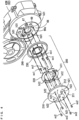
- Fig. 4 is an exploded perspective view for explaining the configurations of the crankcase 62 and the dynamic damper 200 of Fig. 2 .
- the crankcase 62 of Fig. 2 is constituted by a plurality of case members.
- the dynamic damper 200 is attached to a case member (hereinafter referred to as a right case member 62R) directed rightwardly of the motorcycle 100 among the plurality of case members of the crankcase 62.)
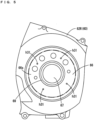
- Fig. 5 is a partially enlarged side view of the right case member 62R of Fig. 4 .
- a bearing fixing portion 66 is provided at the right case member 62R.
- a bearing opening 67 is formed in the center portion of the bearing fixing portion 66.
- the bearing opening 67 is a circular opening through which the right end portion of the crankshaft 61 can be inserted.
- the bearing fixing portion 66 has an annular bearing fitting portion 69 at the inner edge of the bearing opening 67 and its peripheral portion.
- the bearing fitting portion 69 is formed such that a bearing BR ( Fig. 10 ), described below, can be fitted to the bearing fitting portion 69 from the inside of the crankcase 62.
- the bearing fixing portion 66 has a substantially annular flat attachment surface 66s that surrounds the bearing opening 67 and the bearing fitting portion 69 and is directed rightwardly of the motorcycle 100.
- the four screw holes h31 that open rightwardly of the motorcycle 100 are formed in the bearing fixing portion 66.
- the four screw holes h31 are arranged in a dispersed manner at equal angular intervals about the center of the bearing opening 67 so as to surround the bearing opening 67 and the bearing fitting portion 69.
- a rubber member 230 of Fig. 4 is provided on the surface of the bearing fitting portion 69 that faces rightwardly as indicated by the thick dotted line in Fig. 5 .
- a rubber member 240 of Fig. 4 is provided in the vicinity of the outer peripheral end portion of the attachment surface 66s.
- four screws sc2 of Fig. 4 are attached to the four screw holes h31.
- the dynamic damper 200 includes a damper mass 210, a support member (supporter) 220 and the rubber members 230, 240.
- the (first) rubber member 230 is an annular member such as an O-ring, and has an inner diameter and an outer diameter corresponding to the bearing fitting portion 69 of the right case member 62R.
- the (second) rubber member 240 is an annular member made of rubber such as an O-ring, and has an inner diameter larger than that of the rubber member 230 and an outer diameter slightly smaller than that of the attachment surface 66s of the right case member 62R. The functions of the rubber member 230 and the rubber member 240 will be described below.
- the damper mass 210 is a substantially disc-shaped member made of metal such as aluminum or stainless steel.
- the outer diameter of the damper mass 210 is equal to the outer diameter of the rubber member 240 or slightly larger than the outer diameter of the rubber member 240.
- One surface and the other surface of the damper mass 210 facing in the mutually opposite directions are respectively referred to as an outer surface 211 and an inner surface 212 of the damper mass 210.
- the outer surface 211 of the damper mass 210 faces in a direction opposite to the right case member 62R (rightwardly). Further, the outer surface 211 of the damper mass 210 is formed so as to gradually bulge from the outer peripheral end portion to the center portion of the damper mass 210. On the other hand, when the dynamic damper 200 is attached to the right case member 62R, the inner surface 212 of the damper mass 210 faces the attachment surface 66s of the right case member 62R.
- Fig. 6 is a diagram showing the inner surface 212 of the damper mass 210. As shown in Fig. 6 , a circular concave portion 212a is formed at the center of the inner surface 212 of the damper mass 210. Further, an annular closing portion r1 is formed so as to surround the concave portion 212a. The concave portion 212a has an inner diameter which is equal or substantially equal to the inner diameter of the bearing opening 67 of the right case member 62R of Fig. 5 .
- the concave portion 212a is formed to be capable of accommodating the right end portion of the crankshaft 61 that projects rightwardly from the right case member 62R, as described below, with the dynamic damper 200 attached to the right case member 62R.
- the annular closing portion r1 has an annular groove to which part of the rubber member 230 of Fig. 4 can be fitted, and has inner and outer diameters corresponding to the bearing fitting portion 69 of the right case member 62R of Fig. 5 .
- the rubber member 230 of Fig. 4 is provided so as to overlap with the annular groove of the annular closing portion r1.
- two groove portions 212b are formed so as to interpose the concave portion 212a and the annular closing portion r1 therebetween.
- Each of the two groove portions 212b extends linearly and is formed so as to be capable of accommodating part of a leaf spring portion (elastic object) 223 ( Fig. 7 ), described below, of the support member 220 of Fig. 4 .
- annular closing portion r2 is formed in a region having a certain width and including the outer peripheral end portion of the damper mass 210.
- the annular closing portion r2 has an annular groove to which part of the rubber member 240 of Fig. 4 can be fitted.
- the rubber member 240 of Fig. 4 is provided so as to overlap with the annular groove of the annular closing portion r2.
- two supported surfaces 212c are formed in a region except for the region between the two groove portions 212b and the annular closing portion r2.
- the two supported surfaces 212c are indicated by the one-dot and dash lines.
- One supported surface 212c is formed at a position outward of the concave portion 212a and between one groove portion 212b and one portion (arc-shaped portion) of the annular closing portion r2.
- the other supported surface 212c is formed at a position outward of the concave portion 212a and between the other groove portion 212b and the other portion (arc-shaped portion) of the annular closing portion r2.
- the two supported surfaces 212c are formed flat.
- Eight through holes extending from the outer surface 211 to the inner surface 212 are formed in the damper mass 210.
- Four through holes h22 out of the eight through holes are arranged in a dispersed manner at equal angular intervals about the center of the concave portion 212a so as to surround the concave portion 212a and the annular closing portion r1 in the region between the two groove portions 212b.
- These four through holes h22 respectively correspond to the four screw holes h31 ( Fig. 5 ) of the right case member 62R, and have a common inner diameter into which each entire screw sc2 (including head portion) out of the four screws sc2 ( Fig. 4 ), described below, can be inserted.
- the rest of the four through holes out of the eight through holes are four screw holes h21.
- the four screw holes h21 have a common inner diameter and a common inner peripheral surface shape.
- Two screw holes h21 are formed to be located in each of the two supported surfaces 212c.
- the four screw holes h21 are used to screw the support member 220 of Fig. 4 to the inner surface 212 of the damper mass 210.
- the four screw holes h21 do not have to penetrate the outer surface 211 and the inner surface 212 of the damper mass 210.
- the four screw holes h21 may open only in the inner surface 212.
- the support member 220 is attached to the inner surface 212 of the damper mass 210.
- the surface facing the inner surface 212 of the damper mass 210 is a front surface of the support member 220.
- Fig. 7 is a front view of the support member 220 of Fig. 4 .
- the direction indicated by the arrow D1 of Fig. 7 is defined as a first direction D1
- the direction indicated by the arrow D2 of Fig. 7 is defined as a second direction D2.
- the first direction D1 and the second direction D2 are orthogonal to each other.
- the direction indicated by the arrow D3 of Fig. 7 orthogonal to the first direction D1 and the second direction D2 is defined as a third direction D3.
- Fig. 8 is a side view of the support member 220 of Fig. 7 as viewed in the first direction D1
- Fig. 9 is a side view of the support member 220 of Fig. 7 as viewed in the second direction D2.
- the support member 220 is constituted by a single member made of metal, and is fabricated by a bending process, a thermal process and the like of a sheet metal cut out into a predetermined shape. As shown in Fig. 7 , the support member 220 has a substantially annular shape in a front view, and is mainly constituted by two case connecting portions 221, two damper mass connecting portions 222 and the two leaf spring portions 223.
- the two case connecting portions 221 are formed to be arranged at a distance from each other in the first direction D1 and extend in the second direction D2.
- Each case connecting portion 221 has one surface and the other surface orthogonal to the third direction D3.
- two through holes h12 are formed in each case connecting portion 221.
- the four through holes h12 of the two case connecting portions 221 correspond to the four screw holes h31 of the right case member 62R ( Fig. 5 ), respectively.
- the inner diameter of each through hole h12 is larger than the outer diameter of the shaft portion of the screw sc2 and is smaller than the outer diameter of the head portion of the screw sc2 ( Fig, 4 ), described below, attached to each screw hole h31.
- the two damper mass connecting portions 222 are formed to be arranged at a distance from each other in the second direction D2 and extend in the first direction D1.
- Each damper mass connecting portion 222 has one surface and the other surface orthogonal to the third direction D3.
- two through holes h11 are formed in each damper mass connecting portion 222.
- the four through holes h11 of the two damper mass connecting portions 222 correspond to the four screw holes h21 ( Fig. 6 ) of the damper mass 210, respectively.
- the inner diameter of each through hole h11 is larger than the outer diameter of the shaft portion of a screw sc1 and is smaller than the outer diameter of the head portion of the screw sc1, described below, attached to each screw hole h21.
- the two leaf spring portions 223 are formed so as to respectively connect the both end portions of the two case connecting portions 221. Further, the two leaf spring portions 223 are formed so as to respectively hold the two damper mass connecting portions 222 at positions between the two case connecting portions 221 in the first direction D1. The two damper mass connecting portions 222 are held at positions slightly deviated from the two case connecting portions 221 in the third direction D3.
- each leaf spring portion 223 is configured to be bent by 90 ° with respect to the case connecting portion 221 and the damper mass connecting portion 222. Therefore, each leaf spring portion 223 has one surface and the other surface orthogonal to the second direction D2.
- the leaf spring portion 223 has a first portion 223a, a second portion 223b and a third portion 223c arranged in the first direction D1.
- the first portion 223a and the third portion 223c of the leaf spring portion 223 are directly coupled to the two case connecting portions 221, respectively.
- the second portion 223b of the leaf spring portion 223 is directly coupled to one damper mass connecting portion 222 at a position between the first portion 223a and the third portion 223c in the first direction D1.
- Fig. 10 is a cross sectional view taken along the line A-A of the power unit 6 of Fig. 2
- Fig. 11 is a cross sectional view taken along the line B-B of the power unit 6 of Fig. 2
- the dynamic damper 200 is attached to the crankcase 62 as described below.
- the bearing BR is fitted to the bearing fitting portion 69 of the right case member 62R.
- a portion in the vicinity of the right end portion of the crankshaft 61 is rotatably held at the right case member 62R.
- the right end portion of the crankshaft 61 slightly projects outwardly (rightwardly) of the bearing fixing portion 66 through the bearing opening 67.
- the support member 220 is positioned on the inner surface 212 of the damper mass 210, such that the two leaf spring portions 223 of Fig. 7 are accommodated in the two groove portions 212b of Fig. 6 and the four through holes h21 of Fig. 7 overlap with the four screw holes h21 of Fig. 6 .
- the four screws sc1 are attached to the four screw holes h21 of the damper mass 210 through the four through holes h11 of the support member 220.
- the two damper mass connecting portions 222 ( Fig. 7 ) of the support member 220 are connected to the two supported surfaces 212c ( Fig.
- the two case connecting portions 221 ( Fig. 7 ) of the support member 220 are positioned such that the four through holes h12 are opposite to the four through holes h22 of the damper mass 210, respectively, with the two case connecting portions 221 of the support member 220 spaced apart from the inner surface 212 of the damper mass 210.
- the rubber member 230 is positioned on the surface, facing rightwardly, of the bearing fitting portion 69 of the right case member 62R. Further, the rubber member 240 is positioned in the vicinity of the outer peripheral end portion of the attachment surface 66s of the right case member 62R.
- the damper mass 210 is positioned on the attachment surface 66s of the right case member 62R such that the rubber member 230 and the rubber member 240 overlap with the annular closing portion r1 and the annular closing portion r2, respectively. Further, the damper mass 210 is positioned on the attachment surface 66s of the right case member 62R such that the four through holes h22 ( Fig. 6 ) of the damper mass 210 overlap with the four screw holes h31 ( Fig. 5 ) of the right case member 62R.
- the four screws sc2 are respectively attached to the four screw holes h31 of the right case member 62R through the four through holes h22 of the damper mass 210 and the four through holes h12 of the support member 220.
- the two case connecting portions 221 ( Fig. 7 ) of the support member 220 are connected to the attachment surface 66s ( Fig. 5 ) of the right case member 62R.
- the dynamic damper 200 is attached to the bearing fixing portion 66 of the right case member 62R.
- the right end portion of the crankshaft 61 projecting from the bearing opening 67 of the bearing fixing portion 66 is accommodated in the concave portion 212a of the damper mass 210.
- the rubber member 230 is provided between the annular closing portion r1 of the damper mass 210 and the bearing fitting portion 69 of the right case member 62R.
- the space around the right end portion of the crankshaft 61 surrounded by the damper mass 210 and the right case member 62R is closed by the rubber member 230 from the space outside of the power unit 6.
- the rubber member 240 is further provided between the damper mass 210 and the attachment surface 66s of the right case member 62R so as to surround the rubber member 230.
- the above-mentioned dynamic damper 200 is attached to the crankcase 62 to absorb at least part of vibration transmitted from the crankshaft 61 to the crankcase 62.
- the operation of the dynamic damper 200 at this time will be described.
- Figs. 12 and 13 are schematic views for explaining the operation of the dynamic damper 200 when the dynamic damper 200 absorbs the vibration transmitted from the crankshaft 61 to the crankcase 62.
- Fig. 12 is a schematic diagram of the dynamic damper 200 as viewed from a position opposite to the outer surface 211 of the damper mass 210.
- Fig. 13 is a cross sectional view of the dynamic damper 200 of Fig. 12 through the center of the dynamic damper 200 of Fig. 12 .
- part of the constituent elements of the dynamic damper 200 is not shown in order to facilitate understanding of the operation of the dynamic damper 200. Further, the scales of dimensions of respective components in the dynamic damper 200 are different.
- one virtual straight line VL1 parallel to the direction of bending vibration of the crankshaft 61 and orthogonal to the crank axis (center axis of the crankshaft) 61c is defined.
- the two leaf spring portions 223 of the support member 220 are provided such that one surface and the other surface thereof are orthogonal to the virtual straight line VL1.
- the direction in which each leaf spring portion 223 can be deformed is limited to a plane substantially parallel to the crank axis 61c and the virtual straight line VL1.
- the support member 220 is attached to the attachment surface 66c such that the two damper mass connecting portions 222 are arranged at a distance from each other on the virtual straight line VL1 as viewed in the direction extending along the crank axis 61c.
- the direction in which the damper mass 210 can be moved is restricted to the direction extending along the virtual straight line VL1 by the two damper mass connecting portions 222 and the two leaf spring portions 223. Therefore, as indicated by the thick solid arrows in Figs. 12 and 13 , when bending vibration is generated in the crankshaft 61, the damper mass 210 vibrates on the virtual straight line VL1 and does not vibrate in a direction deviating from the virtual straight line VL1. Therefore, at least part of the bending vibration generated in the crankshaft 61 is efficiently absorbed by the vibration of the damper mass 210.
- the support member 220 is attached to the attachment surface 66s such that the crankshaft 61 is located between the two damper mass connecting portions 222 as viewed in the direction extending along the crank axis 61c. Further, the support member 220 is attached to the attachment surface 66s such that the crankshaft 61 is located between the two case connecting portions 221 as viewed in the direction extending along the crank axis 61c.
- the damper mass 210 overlaps with at least the crankshaft 61 on the virtual straight line VL as viewed in the direction extending along the crank axis 61c.
- instability of the center of gravity of the engine 6A due to the vibration of the damper mass 210 is suppressed as compared with a case in which the damper mass 210 is provided at a position greatly deviated from the crankshaft 61 as viewed in the direction extending along the crank axis 61c.
- the frequency of vibration that can be attenuated by the dynamic damper 200 is an eigenvalue, and the eigenvalue is defined mainly based on the weight of the damper mass 210 and an elastic force of the leaf spring portion 223. Therefore, it is preferable that the weight of the damper mass 210 and the elastic force of the leaf spring portion 223 are defined such that the frequency of vibration that can be attenuated by the dynamic damper 200 matches a specific frequency band in advance.
- the specific frequency band is a frequency band that greatly contributes to noise at a higher level of noise generated from the motorcycle 100 during an operation of the engine 6A. It is preferable that the weight of the damper mass 210 and the elastic force of the leaf spring portion 223 are set, and the specific frequency band is selected, through an experiment or a simulation, for example.
- an engine has been operated under a predetermined common condition and measured the magnitude of generated noise having a wavelength in a specific range during the operation. As a result, it was confirmed that the level of noise generated from the power unit of the preferred example was lower than the level of noise generated from the power unit of the comparative example.
- the crankshaft 61 is an example of a crankshaft
- the crankcase 62 is an example of a crankcase
- the dynamic damper 200 is an example of a dynamic damper
- the damper mass 210 is an example of a damper mass
- the virtual straight line VL1 is an example of one straight line
- the support member 220 is an example of a support member
- the power unit 6 and the engine 6A are examples of an engine.
- crank axis 61c is an example of a center axis of a crankshaft
- attachment surface 66s of the right case member 62R is an example of an attachment surface
- one leaf spring portion 223 of the two leaf spring portions 223 of the support member 220 is an example of a first leaf spring portion
- the other leaf spring portion 223 of the two leaf spring portions 223 of the support member 220 is an example of a second leaf spring portion
- one case connecting portion 221 of the two case connecting portions 221 of the support member 220 is an example of a first portion
- the other case connecting portion 221 of the two case connecting portions 221 of the support member 220 is an example of a second portion.
- each of the leaf spring portions 223 of the support member 220 are examples of one surface and another surface facing in mutually opposite directions of each of the first leaf spring portion and the second leaf spring portion
- the rubber members 230, 240 are examples of a rubber member
- the bearing BR is an example of a bearing
- the bearing fixing portion 66 of the right case member 62R is an example of a fixing portion
- the rear wheel 8 is an example of a drive wheel
- the entire motorcycle 100 excluding the power unit 6 is an example of a main body
- the motorcycle 100 is an example of a straddled vehicle.
Landscapes
- Engineering & Computer Science (AREA)
- General Engineering & Computer Science (AREA)
- Mechanical Engineering (AREA)
- Chemical & Material Sciences (AREA)
- Combustion & Propulsion (AREA)
- Physics & Mathematics (AREA)
- Acoustics & Sound (AREA)
- Vibration Prevention Devices (AREA)
- Cylinder Crankcases Of Internal Combustion Engines (AREA)
Abstract
Description
- The present invention relates to an engine and a straddled vehicle including the engine.
- When vibration generated in a crankshaft during an operation of an engine is transmitted to a crankcase, noise is generated from a power unit or the like including the crankcase. In order to reduce such noise,
JP 2002-005235 A - More specifically, in the engine described in
JP 2002-005235 A - Further, in the above-mentioned dynamic damper, the antivibration performance of the damper weight is set in consideration of the fact that the rigidity of the crankcase varies depending on a direction. The antivibration performance of the damper weight needs to be set in consideration of not only the ratio of the mass of a damper weight to the mass of a crankshaft and the composition of the elastic object but also the arrangement of the peripheral members of the damper weight, the allowable size of the damper weight, and the like. Therefore, it is not easy to provide the dynamic damper at the crankshaft rotating at high speed and appropriately set the antivibration performance. Therefore, it is not easy to fabricate the above-mentioned engine.
- Further, in the engine described in
JP 2002-005235 A - An object of the present invention is to provide an engine which can be easily fabricated and can reduce generation of noise, and a straddled vehicle including the engine. According to the present invention said object is solved by an engine having the features of
independent claim 1. Preferred embodiments are laid down in the dependent claims. - (1) An engine according to one aspect includes a crankshaft, a crankcase accommodating the crankshaft, and a dynamic damper provided at the crankcase, wherein the dynamic damper includes a damper mass, and a supporter that has an elastic object, and vibratably supports the damper mass at the crankcase such that the damper mass is vibratable by the elastic object on one straight line that is orthogonal to a center axis of the crankshaft and parallel to a direction of bending vibration generated in the crankshaft.
- In the engine, the dynamic damper is provided in the crankcase. In this case, because it is not necessary to provide the dynamic damper at the crankshaft that rotates at high speed, the degree of freedom in design and attachment of the dynamic damper is improved, and the engine can be easily fabricated. Further, with the above-mentioned configuration, the damper mass of the dynamic damper vibrates on the one straight line parallel to the direction of the bending vibration of the crankshaft. Thus, the vibration transmitted to the peripheral members of the crankshaft due to the bending vibration of the crankshaft is efficiently absorbed by the dynamic damper. Therefore, at least part of vibration that causes noise generated from the power unit including the crankcase and its peripheral members is efficiently absorbed by the dynamic damper. As a result, the engine which is easily fabricated and in which generation of noise is reduced is realized.
- (2) The supporter may vibratably support the damper mass at the crankcase such that an elastic force of the elastic object is exerted on the damper mass on the one straight line, while the supporter restricts a vibration direction of the damper mass such that the damper mass is not vibratable on another straight line that intersects with the one straight line.
- With the above-mentioned configuration, the damper mass of the dynamic damper vibrates only on the one straight line parallel to the direction of the bending vibration of the crankshaft. Thus, vibration that causes noise is more efficiently absorbed.
- (3) The supporter may have a first leaf spring portion and a second leaf spring portion as the elastic objects, the first leaf spring portion and the second leaf spring portion may be provided at the crankcase to be arranged at a distance from each other in a direction parallel to the one straight line, and each of the first leaf spring portion and the second leaf spring portion may be provided to connect the crankcase and the damper mass to each other.
- The leaf spring has a thickness that is smaller than that of other elastic members such as a coil spring and a rubber member. Therefore, with the above-mentioned configuration, it is possible to restrict the vibration direction of the damper mass with respect to the crankcase without requiring an excessive installation space.
- (4) Each of the first leaf spring portion and the second leaf spring portion may be formed in a flat plate shape having one surface and another surface that face in mutually opposite directions, and may be provided at the crankcase such that the one surface and the another surface are orthogonal to the one straight line. In this case, each of the first leaf spring portion and the second leaf spring portion is bent in a plane orthogonal to the center axis of the crankshaft, so that the damper mass vibrates on the one straight line with a simple configuration.
- (5) The crankcase may have an attachment surface that is orthogonal to a center axis of the crankshaft, the supporter may have a first portion and a second portion attached to the attachment surface, and the crankshaft may be located in a region between a portion to which the first portion of the supporter is attached in the attachment surface and a portion to which the second portion of the supporter is attached in the attachment surface when being viewed in a direction extending along the center axis of the crankshaft.
- In this case, the damper mass can be arranged in the vicinity of the crankshaft when being viewed in the direction extending along the center axis of the crankshaft. For example, the damper mass can be arranged to overlap with the crankshaft. Thus, instability of the center of gravity of the engine due to vibration of the damper mass is suppressed as compared with a case in which the damper mass is provided at a position greatly deviated from the crankshaft.
- (6) The dynamic damper may further include a rubber member provided between the attachment surface of the crankcase and the damper mass. In this case, the rubber member absorbs the vibration of the damper mass caused by the elastic forces of the first leaf spring portion and the second leaf spring portion. Thus, generation of noise due to strong vibration of the damper mass is suppressed.
- (7) The engine may further include a bearing that supports the crankshaft in the crankcase, wherein the crankcase may have a fixing portion to which the bearing is fixed, and the dynamic damper may be attached to the fixing portion.
- The fixing portion of the crankcase supports the crankshaft via the bearing. Therefore, vibration is easily transmitted from the crankshaft to the fixing portion. With the above-mentioned configuration, because the dynamic damper is attached to the fixing portion, large part of vibration transmitted from the crankshaft to the crankcase is efficiently absorbed by the dynamic damper.
- (8) A straddled vehicle according to another aspect includes a main body having a drive wheel, and the above-mentioned engine that generates motive power for rotating the drive wheel.
- The straddled vehicle includes the above-mentioned engine. This facilitates fabrication of the straddled vehicle. Further, at least part of vibration that causes noise generated from the power unit including the crankcase and its peripheral members is efficiently absorbed by the dynamic damper. As a result, the straddled vehicle which is easily fabricated and in which generation of noise is reduced is realized.
- Other features, elements, characteristics, and advantages of the present disclosure will become more apparent from the following description of preferred embodiments of the present disclosure with reference to the attached drawings.
-
-
Fig. 1 is a right side view of a motorcycle according to a preferred embodiment; -
Fig. 2 is a side view of a power unit ofFig. 1 as viewed from a position farther rightward than the motorcycle; -
Fig. 3 is a diagram for explaining bending vibration generated in a crankshaft ofFig. 2 ; -
Fig. 4 is an exploded perspective view for explaining the configurations of a crankcase and a dynamic damper ofFig. 2 ; -
Fig. 5 is a partially enlarged side view of a right case member ofFig. 4 ; -
Fig. 6 is a diagram showing an inner surface of a damper mass; -
Fig. 7 is a front view of a support member ofFig. 4 ; -
Fig. 8 is a side view of the support member ofFig. 7 as viewed in a first direction; -
Fig. 9 is a side view of the support member ofFig. 7 as viewed in a second direction; -
Fig. 10 is a cross sectional view of the power unit ofFig. 2 taken along the line A-A; -
Fig. 11 is a cross sectional view of the power unit ofFig. 2 taken along the line B-B; -
Fig. 12 is a schematic diagram for explaining an operation of the dynamic damper when vibration transmitted from the crankshaft to the crankcase is absorbed; and -
Fig. 13 is a schematic diagram for explaining the operation of the dynamic damper when the vibration transmitted from the crankshaft to the crankcase is absorbed. - An engine and a straddled vehicle including the engine according to a preferred embodiment will be described below with reference to the drawings. A motorcycle will be described as one example of the straddled vehicle.
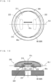
-
Fig. 1 is a right side view of a motorcycle according to the preferred embodiment. InFig. 1 , themotorcycle 100 standing up to be perpendicular to the road surface is shown. Themotorcycle 100 ofFig. 1 includes ametallic body frame 1. Thebody frame 1 includes ahead pipe 11 and a plurality of frame members. InFig. 1 , twoframe members head pipe 11 is located in a front portion of the vehicle. Theframe members head pipe 11. - A
front fork 2 is provided at thehead pipe 11 to be rotatable about the center axis of thehead pipe 11. Afront wheel 3 is rotatably supported at the lower end portion of thefront fork 2. Ahandle 4 is provided at the upper end portion of thefront fork 2. - The
body frame 1 supports a plurality of constituent elements of themotorcycle 100 including aseat 5, apower unit 6 and arear arm 7. Theseat 5 is provided in a substantially central upper portion of themotorcycle 100 in a front-and-rear direction. Thepower unit 6 includes anengine 6A and is provided at a substantially central lower portion of themotorcycle 100 in the front-and-rear direction. A side cover made of resin is provided so as to interpose the front half portion (the portion of theengine 6A) of thepower unit 6 in a left-and-right direction of themotorcycle 100. - A
rear arm 7 is provided to extend rearwardly from a position in the vicinity of the rear end portion of thepower unit 6. Therear arm 7 is supported at thebody frame 1 with use of a pivot shaft (not shown). Arear wheel 8 is rotatably supported at the rear end portion of therear arm 7. Therear wheel 8 is rotated as a drive wheel by the motive power generated by theengine 6A of thepower unit 6. - During an operation of the
engine 6A, noise may be generated from themotorcycle 100 as thecrankshaft 61 included in theengine 6A rotates. As such, in thepower unit 6 according to the present embodiment, adynamic damper 200 is provided as the configuration for reducing noise generated during an operation of the engine. The mechanism of generation of noise and the specific configuration and function of thedynamic damper 200 will be described. -
Fig. 2 is a side view of thepower unit 6 ofFig. 1 as viewed from a position farther rightward than the motorcycle. As described above, thepower unit 6 includes theengine 6A. Theengine 6A has acylinder head 63. Thecylinder head 63 has the configuration in which two cylinders are arranged in the left-and-right direction of themotorcycle 100. InFig. 2 , the outer shape of thecylinder head 63 is schematically shown by the one-dot and dash lines. - The
power unit 6 includes acrankcase 62. Thecrankcase 62 according to the present embodiment accommodates thecrankshaft 61. Thecrankshaft 61 extends in the left-and-right direction of themotorcycle 100 in thecrankcase 62. - Two
pistons 64 are connected to thecrankshaft 61 via two connectingrods 65, respectively. The twopistons 64 of thecrankshaft 61 are respectively provided so as to be reciprocatable in the two cylinders of thecylinder head 63. InFig. 2 , aright piston 64 and aright connecting rod 65 located in thecylinder head 63 are indicated by the solid lines. Further, inFig. 2 , the virtual straight line passing through the center axis of a right cylinder of thecylinder head 63 is indicated by the two-dots and dash line as a cylinder axis AS. - During an operation of the
engine 6A, bending vibration is generated in thecrankshaft 61.Fig. 3 is a diagram for explaining the bending vibration generated in thecrankshaft 61 ofFig. 2 . InFig. 3 , the outer shape of thepower unit 6 as viewed from a position above thepower unit 6 in the direction indicated by the outlined arrow VP1 ofFig. 2 is shown. Further, inFig. 3 , thecrankshaft 61, the twopistons 64 and the two connectingrods 65 provided in thepower unit 6 are indicated by the solid lines. Further, inFig. 3 , the virtual straight line passing through the center axis of thecrankshaft 61 is indicated by the two-dots and dash line as acrank axis 61c. The direction of the outlined arrow VP1 ofFig. 2 is the direction orthogonal to the cylinder axis AS when thepower unit 6 is viewed in the direction extending along the center axis (crankaxis 61c) of thecrankshaft 61. - When the
crankshaft 61 rotates during an operation of theengine 6A, the twopistons 64 connected to thecrankshaft 61 reciprocate along the cylinder axis AS. In this case, a bending moment is generated in thecrankshaft 61 in a predetermined period by a pressure of a fuel-air mixture exerted on eachpiston 64 and an inertial force. Thus, as indicated by the thick dotted lines inFig. 3 , in thecrankshaft 61, the center portion thereof is bent in the direction toward thecylinder head 63 and then in the direction away from thecylinder head 63, repeatedly. - As a result, in the present example, as indicated by the thick solid arrows in
Figs. 2 and3 , thecrankshaft 61 vibrates with respect to thecylinder head 63 in a plane parallel to the two cylinder axes AS of thecylinder head 63 and the left-and-right direction of themotorcycle 100. This vibration is the bending vibration of thecrankshaft 61. Here, the direction of the bending vibration of thecrankshaft 61 is the direction in which thecrankshaft 61 vibrates due to a bending moment generated in thecrankshaft 61 during an operation of theengine 6A. The direction of the bending vibration of thecrankshaft 61 of the present example is the direction parallel to the cylinder axes AS in a side view and orthogonal to the center axis (crankaxis 61c) of thecrankshaft 61 in a plan view. - When the bending vibration of the
crankshaft 61 having a specific frequency (a frequency in a certain range including a 800 Hz, for example) is transmitted to part of thecrankcase 62, noise may be generated due to vibration of the part of thecrankcase 62. For example, when part of the outer surface of thecrankcase 62 is repeatedly deformed in a concave shape and a convex shape due to the bending vibration of thecrankshaft 61, a relatively large noise is likely to be generated. Alternatively, when the bending vibration of thecrankshaft 61 having a specific frequency is transmitted to part of theframe members crankcase 62, noise may be generated due to vibration of part of theframe members frame members motorcycle 100 according to the present embodiment, thedynamic damper 200 is provided in thecrankcase 62 in order to efficiently reduce the vibration transmitted from thecrankshaft 61 to another member such as thecrankcase 62. -
Fig. 4 is an exploded perspective view for explaining the configurations of thecrankcase 62 and thedynamic damper 200 ofFig. 2 . Thecrankcase 62 ofFig. 2 is constituted by a plurality of case members. Thedynamic damper 200 is attached to a case member (hereinafter referred to as aright case member 62R) directed rightwardly of themotorcycle 100 among the plurality of case members of thecrankcase 62.) -
Fig. 5 is a partially enlarged side view of theright case member 62R ofFig. 4 . As shown inFig. 5 , abearing fixing portion 66 is provided at theright case member 62R. A bearingopening 67 is formed in the center portion of thebearing fixing portion 66. The bearingopening 67 is a circular opening through which the right end portion of thecrankshaft 61 can be inserted. - The
bearing fixing portion 66 has an annularbearing fitting portion 69 at the inner edge of thebearing opening 67 and its peripheral portion. The bearingfitting portion 69 is formed such that a bearing BR (Fig. 10 ), described below, can be fitted to the bearingfitting portion 69 from the inside of thecrankcase 62. Further, thebearing fixing portion 66 has a substantially annularflat attachment surface 66s that surrounds thebearing opening 67 and the bearingfitting portion 69 and is directed rightwardly of themotorcycle 100. - Four screw holes h31 that open rightwardly of the
motorcycle 100 are formed in thebearing fixing portion 66. The four screw holes h31 are arranged in a dispersed manner at equal angular intervals about the center of the bearing opening 67 so as to surround thebearing opening 67 and the bearingfitting portion 69. - When the
dynamic damper 200 is attached to theright case member 62R, arubber member 230 ofFig. 4 , described below, is provided on the surface of the bearingfitting portion 69 that faces rightwardly as indicated by the thick dotted line inFig. 5 . Further, as indicated by the thick one-dot and dash line inFig. 5 , arubber member 240 ofFig. 4 , described below, is provided in the vicinity of the outer peripheral end portion of theattachment surface 66s. Further, four screws sc2 ofFig. 4 , described below, are attached to the four screw holes h31. - As shown in
Fig. 4 , thedynamic damper 200 includes adamper mass 210, a support member (supporter) 220 and therubber members rubber member 230 is an annular member such as an O-ring, and has an inner diameter and an outer diameter corresponding to the bearingfitting portion 69 of theright case member 62R. The (second)rubber member 240 is an annular member made of rubber such as an O-ring, and has an inner diameter larger than that of therubber member 230 and an outer diameter slightly smaller than that of theattachment surface 66s of theright case member 62R. The functions of therubber member 230 and therubber member 240 will be described below. - The
damper mass 210 is a substantially disc-shaped member made of metal such as aluminum or stainless steel. The outer diameter of thedamper mass 210 is equal to the outer diameter of therubber member 240 or slightly larger than the outer diameter of therubber member 240. One surface and the other surface of thedamper mass 210 facing in the mutually opposite directions are respectively referred to as anouter surface 211 and aninner surface 212 of thedamper mass 210. - When the
dynamic damper 200 is attached to theright case member 62R, theouter surface 211 of thedamper mass 210 faces in a direction opposite to theright case member 62R (rightwardly). Further, theouter surface 211 of thedamper mass 210 is formed so as to gradually bulge from the outer peripheral end portion to the center portion of thedamper mass 210. On the other hand, when thedynamic damper 200 is attached to theright case member 62R, theinner surface 212 of thedamper mass 210 faces theattachment surface 66s of theright case member 62R. -
Fig. 6 is a diagram showing theinner surface 212 of thedamper mass 210. As shown inFig. 6 , a circularconcave portion 212a is formed at the center of theinner surface 212 of thedamper mass 210. Further, an annular closing portion r1 is formed so as to surround theconcave portion 212a. Theconcave portion 212a has an inner diameter which is equal or substantially equal to the inner diameter of the bearing opening 67 of theright case member 62R ofFig. 5 . - The
concave portion 212a is formed to be capable of accommodating the right end portion of thecrankshaft 61 that projects rightwardly from theright case member 62R, as described below, with thedynamic damper 200 attached to theright case member 62R. The annular closing portion r1 has an annular groove to which part of therubber member 230 ofFig. 4 can be fitted, and has inner and outer diameters corresponding to the bearingfitting portion 69 of theright case member 62R ofFig. 5 . When thedynamic damper 200 is attached to theright case member 62R, therubber member 230 ofFig. 4 is provided so as to overlap with the annular groove of the annular closing portion r1. - In the
inner surface 212 of thedamper mass 210, twogroove portions 212b are formed so as to interpose theconcave portion 212a and the annular closing portion r1 therebetween. Each of the twogroove portions 212b extends linearly and is formed so as to be capable of accommodating part of a leaf spring portion (elastic object) 223 (Fig. 7 ), described below, of thesupport member 220 ofFig. 4 . - In the
inner surface 212 of thedamper mass 210, an annular closing portion r2 is formed in a region having a certain width and including the outer peripheral end portion of thedamper mass 210. The annular closing portion r2 has an annular groove to which part of therubber member 240 ofFig. 4 can be fitted. When thedynamic damper 200 is attached to theright case member 62R, therubber member 240 ofFig. 4 is provided so as to overlap with the annular groove of the annular closing portion r2. - In the
inner surface 212 of thedamper mass 210, two supportedsurfaces 212c are formed in a region except for the region between the twogroove portions 212b and the annular closing portion r2. InFig. 6 , the two supportedsurfaces 212c are indicated by the one-dot and dash lines. One supportedsurface 212c is formed at a position outward of theconcave portion 212a and between onegroove portion 212b and one portion (arc-shaped portion) of the annular closing portion r2. The other supportedsurface 212c is formed at a position outward of theconcave portion 212a and between theother groove portion 212b and the other portion (arc-shaped portion) of the annular closing portion r2. The two supportedsurfaces 212c are formed flat. When thedynamic damper 200 is attached to theright case member 62R, two damper mass connecting portions 222 (Fig. 7 ), described below, of thesupport member 220 ofFig. 4 abut against the two supportedsurfaces 212c, respectively. InFig. 6 , the dotted pattern is applied to the portions of the two supportedsurfaces 212c against which the two damper mass connecting portions 222 (Fig, 7 ), described below, abut. - Eight through holes extending from the
outer surface 211 to theinner surface 212 are formed in thedamper mass 210. Four through holes h22 out of the eight through holes are arranged in a dispersed manner at equal angular intervals about the center of theconcave portion 212a so as to surround theconcave portion 212a and the annular closing portion r1 in the region between the twogroove portions 212b. These four through holes h22 respectively correspond to the four screw holes h31 (Fig. 5 ) of theright case member 62R, and have a common inner diameter into which each entire screw sc2 (including head portion) out of the four screws sc2 (Fig. 4 ), described below, can be inserted. - The rest of the four through holes out of the eight through holes are four screw holes h21. The four screw holes h21 have a common inner diameter and a common inner peripheral surface shape. Two screw holes h21 are formed to be located in each of the two supported
surfaces 212c. The four screw holes h21 are used to screw thesupport member 220 ofFig. 4 to theinner surface 212 of thedamper mass 210. The four screw holes h21 do not have to penetrate theouter surface 211 and theinner surface 212 of thedamper mass 210. The four screw holes h21 may open only in theinner surface 212. - As described above, in the
dynamic damper 200, thesupport member 220 is attached to theinner surface 212 of thedamper mass 210. In the present example, in thesupport member 220 ofFig. 4 , the surface facing theinner surface 212 of thedamper mass 210 is a front surface of thesupport member 220. -
Fig. 7 is a front view of thesupport member 220 ofFig. 4 . Here, in regard to thesupport member 220, in a front view of thesupport member 220, the direction indicated by the arrow D1 ofFig. 7 is defined as a first direction D1, and the direction indicated by the arrow D2 ofFig. 7 is defined as a second direction D2. The first direction D1 and the second direction D2 are orthogonal to each other. Further, the direction indicated by the arrow D3 ofFig. 7 orthogonal to the first direction D1 and the second direction D2 is defined as a third direction D3.Fig. 8 is a side view of thesupport member 220 ofFig. 7 as viewed in the first direction D1, andFig. 9 is a side view of thesupport member 220 ofFig. 7 as viewed in the second direction D2. - The
support member 220 is constituted by a single member made of metal, and is fabricated by a bending process, a thermal process and the like of a sheet metal cut out into a predetermined shape. As shown inFig. 7 , thesupport member 220 has a substantially annular shape in a front view, and is mainly constituted by twocase connecting portions 221, two dampermass connecting portions 222 and the twoleaf spring portions 223. - In the front view of the
support member 220, the twocase connecting portions 221 are formed to be arranged at a distance from each other in the first direction D1 and extend in the second direction D2. Eachcase connecting portion 221 has one surface and the other surface orthogonal to the third direction D3. Further, two through holes h12 are formed in eachcase connecting portion 221. The four through holes h12 of the twocase connecting portions 221 correspond to the four screw holes h31 of theright case member 62R (Fig. 5 ), respectively. The inner diameter of each through hole h12 is larger than the outer diameter of the shaft portion of the screw sc2 and is smaller than the outer diameter of the head portion of the screw sc2 (Fig, 4 ), described below, attached to each screw hole h31. - In the front view of the
support member 220, the two dampermass connecting portions 222 are formed to be arranged at a distance from each other in the second direction D2 and extend in the first direction D1. Each dampermass connecting portion 222 has one surface and the other surface orthogonal to the third direction D3. Further, two through holes h11 are formed in each dampermass connecting portion 222. The four through holes h11 of the two dampermass connecting portions 222 correspond to the four screw holes h21 (Fig. 6 ) of thedamper mass 210, respectively. The inner diameter of each through hole h11 is larger than the outer diameter of the shaft portion of a screw sc1 and is smaller than the outer diameter of the head portion of the screw sc1, described below, attached to each screw hole h21. - In the front view of the
support member 220, the twoleaf spring portions 223 are formed so as to respectively connect the both end portions of the twocase connecting portions 221. Further, the twoleaf spring portions 223 are formed so as to respectively hold the two dampermass connecting portions 222 at positions between the twocase connecting portions 221 in the first direction D1. The two dampermass connecting portions 222 are held at positions slightly deviated from the twocase connecting portions 221 in the third direction D3. - As shown in
Fig. 8 , eachleaf spring portion 223 is configured to be bent by 90 ° with respect to thecase connecting portion 221 and the dampermass connecting portion 222. Therefore, eachleaf spring portion 223 has one surface and the other surface orthogonal to the second direction D2. - As shown in
Fig. 9 , theleaf spring portion 223 has afirst portion 223a, asecond portion 223b and athird portion 223c arranged in the first direction D1. Thefirst portion 223a and thethird portion 223c of theleaf spring portion 223 are directly coupled to the twocase connecting portions 221, respectively. Further, thesecond portion 223b of theleaf spring portion 223 is directly coupled to one dampermass connecting portion 222 at a position between thefirst portion 223a and thethird portion 223c in the first direction D1. With such a configuration, in a case in which a force directed in the second direction D2 is exerted on the dampermass connecting portion 222 with the twocase connecting portions 221 fixed, for example, thesecond portion 223b of theleaf spring portion 223 is locally bent by the elastic force. Thus, the dampermass connecting portion 222 moves in the second direction D2 with respect to the twocase connecting portions 221. -
Fig. 10 is a cross sectional view taken along the line A-A of thepower unit 6 ofFig. 2 , andFig. 11 is a cross sectional view taken along the line B-B of thepower unit 6 ofFig. 2 . Thedynamic damper 200 is attached to thecrankcase 62 as described below. As shown inFigs. 10 and11 , at a point in time at which attachment of thedynamic damper 200 to thecrankcase 62 is started, the bearing BR is fitted to the bearingfitting portion 69 of theright case member 62R. Further, a portion in the vicinity of the right end portion of thecrankshaft 61 is rotatably held at theright case member 62R. Further, the right end portion of thecrankshaft 61 slightly projects outwardly (rightwardly) of thebearing fixing portion 66 through thebearing opening 67. - First, the
support member 220 is positioned on theinner surface 212 of thedamper mass 210, such that the twoleaf spring portions 223 ofFig. 7 are accommodated in the twogroove portions 212b ofFig. 6 and the four through holes h21 ofFig. 7 overlap with the four screw holes h21 ofFig. 6 . In this state, as indicated by the dotted arrows inFig. 4 , the four screws sc1 are attached to the four screw holes h21 of thedamper mass 210 through the four through holes h11 of thesupport member 220. Thus, as shown inFig. 10 , the two damper mass connecting portions 222 (Fig. 7 ) of thesupport member 220 are connected to the two supportedsurfaces 212c (Fig. 6 ) of thedamper mass 210. In this case, the two case connecting portions 221 (Fig. 7 ) of thesupport member 220 are positioned such that the four through holes h12 are opposite to the four through holes h22 of thedamper mass 210, respectively, with the twocase connecting portions 221 of thesupport member 220 spaced apart from theinner surface 212 of thedamper mass 210. - Next, the
rubber member 230 is positioned on the surface, facing rightwardly, of the bearingfitting portion 69 of theright case member 62R. Further, therubber member 240 is positioned in the vicinity of the outer peripheral end portion of theattachment surface 66s of theright case member 62R. In this state, thedamper mass 210 is positioned on theattachment surface 66s of theright case member 62R such that therubber member 230 and therubber member 240 overlap with the annular closing portion r1 and the annular closing portion r2, respectively. Further, thedamper mass 210 is positioned on theattachment surface 66s of theright case member 62R such that the four through holes h22 (Fig. 6 ) of thedamper mass 210 overlap with the four screw holes h31 (Fig. 5 ) of theright case member 62R. - Thereafter, as indicated by the thick one-dot and dash arrows in
Fig. 4 , the four screws sc2 are respectively attached to the four screw holes h31 of theright case member 62R through the four through holes h22 of thedamper mass 210 and the four through holes h12 of thesupport member 220. Thus, as shown inFig. 11 , the two case connecting portions 221 (Fig. 7 ) of thesupport member 220 are connected to theattachment surface 66s (Fig. 5 ) of theright case member 62R. In this manner, thedynamic damper 200 is attached to thebearing fixing portion 66 of theright case member 62R. - With the
dynamic damper 200 attached to thecrankcase 62, the right end portion of thecrankshaft 61 projecting from the bearing opening 67 of thebearing fixing portion 66 is accommodated in theconcave portion 212a of thedamper mass 210. Therubber member 230 is provided between the annular closing portion r1 of thedamper mass 210 and the bearingfitting portion 69 of theright case member 62R. Thus, the space around the right end portion of thecrankshaft 61 surrounded by thedamper mass 210 and theright case member 62R is closed by therubber member 230 from the space outside of thepower unit 6. Further, therubber member 240 is further provided between thedamper mass 210 and theattachment surface 66s of theright case member 62R so as to surround therubber member 230. With such a configuration, in thepower unit 6 of the present example, oil supplied to the right end portion of thecrankshaft 61 is prevented from leaking from the inside of thecrankcase 62 through the attachment portion of thedynamic damper 200. - The above-mentioned
dynamic damper 200 is attached to thecrankcase 62 to absorb at least part of vibration transmitted from thecrankshaft 61 to thecrankcase 62. The operation of thedynamic damper 200 at this time will be described. -
Figs. 12 and 13 are schematic views for explaining the operation of thedynamic damper 200 when thedynamic damper 200 absorbs the vibration transmitted from thecrankshaft 61 to thecrankcase 62.Fig. 12 is a schematic diagram of thedynamic damper 200 as viewed from a position opposite to theouter surface 211 of thedamper mass 210.Fig. 13 is a cross sectional view of thedynamic damper 200 ofFig. 12 through the center of thedynamic damper 200 ofFig. 12 . InFigs. 12 and 13 , part of the constituent elements of thedynamic damper 200 is not shown in order to facilitate understanding of the operation of thedynamic damper 200. Further, the scales of dimensions of respective components in thedynamic damper 200 are different. - As indicated by the one-dot and dash lines in
Figs. 12 and 13 , one virtual straight line VL1 parallel to the direction of bending vibration of thecrankshaft 61 and orthogonal to the crank axis (center axis of the crankshaft) 61c is defined. In this case, the twoleaf spring portions 223 of thesupport member 220 are provided such that one surface and the other surface thereof are orthogonal to the virtual straight line VL1. Thus, the direction in which eachleaf spring portion 223 can be deformed is limited to a plane substantially parallel to the crankaxis 61c and the virtual straight line VL1. Further, as shown inFig. 12 , thesupport member 220 is attached to the attachment surface 66c such that the two dampermass connecting portions 222 are arranged at a distance from each other on the virtual straight line VL1 as viewed in the direction extending along thecrank axis 61c. - In these cases, the direction in which the
damper mass 210 can be moved is restricted to the direction extending along the virtual straight line VL1 by the two dampermass connecting portions 222 and the twoleaf spring portions 223. Therefore, as indicated by the thick solid arrows inFigs. 12 and 13 , when bending vibration is generated in thecrankshaft 61, thedamper mass 210 vibrates on the virtual straight line VL1 and does not vibrate in a direction deviating from the virtual straight line VL1. Therefore, at least part of the bending vibration generated in thecrankshaft 61 is efficiently absorbed by the vibration of thedamper mass 210. - Further, the
support member 220 is attached to theattachment surface 66s such that thecrankshaft 61 is located between the two dampermass connecting portions 222 as viewed in the direction extending along thecrank axis 61c. Further, thesupport member 220 is attached to theattachment surface 66s such that thecrankshaft 61 is located between the twocase connecting portions 221 as viewed in the direction extending along thecrank axis 61c. - With such a configuration, the
damper mass 210 overlaps with at least thecrankshaft 61 on the virtual straight line VL as viewed in the direction extending along thecrank axis 61c. Thus, instability of the center of gravity of theengine 6A due to the vibration of thedamper mass 210 is suppressed as compared with a case in which thedamper mass 210 is provided at a position greatly deviated from thecrankshaft 61 as viewed in the direction extending along thecrank axis 61c. - The frequency of vibration that can be attenuated by the
dynamic damper 200 is an eigenvalue, and the eigenvalue is defined mainly based on the weight of thedamper mass 210 and an elastic force of theleaf spring portion 223. Therefore, it is preferable that the weight of thedamper mass 210 and the elastic force of theleaf spring portion 223 are defined such that the frequency of vibration that can be attenuated by thedynamic damper 200 matches a specific frequency band in advance. The specific frequency band is a frequency band that greatly contributes to noise at a higher level of noise generated from themotorcycle 100 during an operation of theengine 6A. It is preferable that the weight of thedamper mass 210 and the elastic force of theleaf spring portion 223 are set, and the specific frequency band is selected, through an experiment or a simulation, for example. -
- (1) In the
power unit 6 according to the present embodiment, thedynamic damper 200 is provided in thecrankcase 62. In this case, because it is not necessary to directly provide thedynamic damper 200 in thecrankshaft 61 which rotates at high speed, a degree of freedom in design and attachment of thedynamic damper 200 is improved, and fabrication of thepower unit 6 is facilitated. Further, with the above-mentioned configuration, thedamper mass 210 of thedynamic damper 200 vibrates on the virtual straight line VL1 parallel to the direction of the bending vibration of thecrankshaft 61. Thus, vibration transmitted to the peripheral members of thecrankshaft 61 due to the bending vibration of thecrankshaft 61 is efficiently absorbed by thedynamic damper 200. Therefore, vibration of thecrankcase 62 and its peripheral members due to the bending vibration of thecrankshaft 61 is efficiently reduced. Alternatively, vibration of at least part of theframe members crankshaft 61 is efficiently reduced. As a result, thepower unit 6 which is easily fabricated and in which generation of noise due to the bending vibration of thecrankshaft 61 is reduced is realized. - (2) The
dynamic damper 200 according to the above-mentioned embodiment includes therubber members attachment surface 66s of theright case member 62R and thedamper mass 210. In this case, as described above, each of therubber members crankcase 62 from leaking from the attachment portion of thedynamic damper 200. Further, therubber members damper mass 210 when bending vibration is generated in thecrankshaft 61. Thus, generation of noise due to excessive vibration of thedamper mass 210 is suppressed. - It has been fabricated a power unit having the same configuration as that of the
power unit 6 according to the above-mentioned embodiment as a power unit of a preferred example. Further, it has been fabricated a power unit having the same configuration as that of thepower unit 6 according to the above-mentioned embodiment except that the above-mentioneddynamic damper 200 is not included, as a power unit of a comparative example. - Further, in regard to the power unit of the preferred example and the power unit of the comparative example, an engine has been operated under a predetermined common condition and measured the magnitude of generated noise having a wavelength in a specific range during the operation. As a result, it was confirmed that the level of noise generated from the power unit of the preferred example was lower than the level of noise generated from the power unit of the comparative example.
-
- (1) While the
dynamic damper 200 is provided in the portion of theright case member 62R that covers the right end portion of thecrankshaft 61 in thepower unit 6 according to the above-mentioned embodiment, the present teaching is not limited to this. Thedynamic damper 200 may be provided in a portion of theright case member 62R that is spaced apart from thecrankshaft 61. For example, thedynamic damper 200 may be provided in any one of the front end portion, the upper end portion, the lower end portion and the rear end portion of thecrankcase 62. Also in these cases, since the vibration direction of thedamper mass 210 is limited to the direction of bending vibration of thecrankshaft 61, the similar effect to that in the above-mentioned embodiment can be obtained. - (2) While the one
dynamic damper 200 is provided at theengine 6A in thepower unit 6 according to the above-mentioned embodiment, the present teaching is not limited to this. In thepower unit 6, not only onedynamic damper 200 but two or threedynamic dampers 200 may be provided. For example, in the above-mentionedpower unit 6, a newdynamic damper 200 may be provided in a left side portion of thecrankcase 62. - (3) In the
dynamic damper 200 according to the above-mentioned embodiment, the twoleaf spring portions 223 of thesupport member 220 are arranged in the direction of the bending vibration of thecrankshaft 61 in a side view of themotorcycle 100. Thus, the vibration direction of thedamper mass 210 is restricted to the direction extending along the one virtual straight line VL1 parallel to the direction of the bending vibration of thecrankshaft 61. However, according to the present teaching, the configuration for restricting the vibration direction of thedamper mass 210 is not limited to the above-mentioned example. Thedynamic damper 200 may have the following configuration instead of the above-mentionedsupport member 220.
In the above-mentionedright case member 62R, a guide shaft extending along the one virtual straight line VL1 is provided, for example. Further, thedamper mass 210 is provided on the guide shaft to be movable in the direction extending along the guide shaft. Further, thedamper mass 210 is allowed to move along the guide shaft in a certain range, and an elastic object (a coil spring, for example) that supports thedamper mass 210 at part of the guide shaft or part of theright case member 62R is provided. Even in a case in which such a configuration is provided in thecrankcase 62, the vibration direction of thedamper mass 210 can be restricted to the direction of the bending vibration of thecrankshaft 61. Thus, similar effects to that of the above-mentioned embodiment can be obtained. - (4) While the
dynamic damper 200 according to the above-mentioned embodiment has the tworubber members crankcase 62 is prevented from leaking to the outside of thepower unit 6 by a configuration other than thedynamic damper 200, thedynamic damper 200 does not have to include at least one of the tworubber members - (5) There is also a power unit of a straddled vehicle that has a configuration in which a crankshaft and a plurality of motive power transmission members attached to the crankshaft are individually accommodated in a plurality of casings integrally connected to one another, for example. For example, there is a configuration in which a casing accommodating a crankshaft and a casing accommodating a belt-type continuously variable transmission (CVT) attached to the crankshaft are integrally connected to each other. Alternatively, there is a configuration in which a casing accommodating a crankshaft and a casing accommodating a drive shaft attached to the crankshaft are integrally connected to each other. Alternatively, there is a configuration in which a casing accommodating a crankshaft and a casing accommodating a clutch attached to the crankshaft are integrally connected to each other. In such a configuration, a plurality of integrally connected casings may be regarded as the crankcase according to the present teaching, and the dynamic damper according to the above-mentioned embodiment may be provided in at least one of the plurality of casings. Also in this case, because a plurality of casings constituting a power unit are integrally connected to one another, the similar effect to that of the above-mentioned embodiment can be obtained.
- (6) While the
support member 220 that supports thedamper mass 210 at theright case member 62R is constituted by the single member including the twoleaf spring portions 223 in thedynamic damper 200 according to the above-mentioned embodiment, the present teaching is not limited to this. As the configuration for supporting thedamper mass 210 at theright case member 62R, thesupport member 220 may be divided into two members such that the twoleaf spring portions 223 are spaced apart from each other.
That is, thedynamic damper 200 may include two support members including two leaf spring members instead of the above-mentionedsupport member 220. In this case, one portion of thedamper mass 210 is supported at one portion of theright case member 62R by one leaf spring member, for example. Further, another portion of thedamper mass 210 is supported at another portion of theright case member 62R by the other leaf spring member. Further, the arrangement and posture of the two leaf spring members are adjusted such that the vibration direction of thedamper mass 210 is parallel to the direction of the bending vibration of thecrankshaft 61. Thus, similar effects to that of the above-mentioned embodiment can be obtained. - (7) In the
dynamic damper 200 according to the above-mentioned embodiment, a weight adjustment member for adjusting the weight of thedamper mass 210 may be attached to thedamper mass 210. In this case, a screw hole for a weight member to which a plurality of types of weight members can be screwed, for example, may be formed in thedamper mass 210. Thus, a weight member having a desired weight can be easily attached to or detached from thedamper mass 210. - (8) While the
engine 6A according to the above-mentioned embodiment includes thecylinder head 63 in which the two cylinders are arranged in the left-and-right direction of themotorcycle 100, the present teaching is not limited to this. Theengine 6A may be configured to include only one cylinder or may be configured to include three, four or more than four cylinders. Further, the configuration of theengine 6A is not limited to the above-mentioned example, and theengine 6A may be configured such that one cylinder or three or more than three cylinders are arranged in the left-and-right direction of themotorcycle 100. Alternatively, theengine 6A may be configured such that one or a plurality of cylinders are arranged in the front-and-rear direction of themotorcycle 100. Further, theengine 6A may be configured such that four cylinders are arranged in a matrix in a plan view, or may be configured such that a plurality of cylinders are arranged in a V shape in a side view.
Although varying depending on the configuration of theengine 6A, the direction of the bending vibration generated in thecrankshaft 61 can be derived from a predetermined dimension of each component. Therefore, even in a case in which the number and arrangement of the cylinders in theengine 6A are different from those in the example of the above-mentioned embodiment, thedynamic damper 200 can be attached to thecrankcase 62 such that thedamper mass 210 vibrates in the direction of bending vibration. - (9) While the above-mentioned embodiment is an example in which the present teaching is applied to a motorcycle, the present teaching is not limited to this. The present teaching may be applied to another straddled vehicle such as a four-wheeled automobile, a motor tricycle or an ATV (All Terrain Vehicle).
- In the following paragraphs, non-limiting examples of correspondences between various elements recited in the claims below and those described above with respect to various preferred embodiments of the present disclosure are explained.
- In the above-mentioned embodiment, the
crankshaft 61 is an example of a crankshaft, thecrankcase 62 is an example of a crankcase, thedynamic damper 200 is an example of a dynamic damper, thedamper mass 210 is an example of a damper mass, the virtual straight line VL1 is an example of one straight line, thesupport member 220 is an example of a support member and thepower unit 6 and theengine 6A are examples of an engine. - Further, the
crank axis 61c is an example of a center axis of a crankshaft, theattachment surface 66s of theright case member 62R is an example of an attachment surface, oneleaf spring portion 223 of the twoleaf spring portions 223 of thesupport member 220 is an example of a first leaf spring portion, the otherleaf spring portion 223 of the twoleaf spring portions 223 of thesupport member 220 is an example of a second leaf spring portion, onecase connecting portion 221 of the twocase connecting portions 221 of thesupport member 220 is an example of a first portion, and the othercase connecting portion 221 of the twocase connecting portions 221 of thesupport member 220 is an example of a second portion. - Further, one surface and another surface of each of the
leaf spring portions 223 of thesupport member 220 are examples of one surface and another surface facing in mutually opposite directions of each of the first leaf spring portion and the second leaf spring portion, therubber members bearing fixing portion 66 of theright case member 62R is an example of a fixing portion, therear wheel 8 is an example of a drive wheel, theentire motorcycle 100 excluding thepower unit 6 is an example of a main body, and themotorcycle 100 is an example of a straddled vehicle.
Claims (11)
- An engine (6A) comprising:a crankshaft (61);a crankcase (62) accommodating the crankshaft (61); anda dynamic damper (200) provided at the crankcase (62), whereinthe dynamic damper (200) includesa damper mass (210), anda supporter (220) that has at least one elastic object (223), and vibratably supports the damper mass (210) at the crankcase (62) such that the damper mass (210) is vibratable by the elastic object (223) on one straight line (VL1) that is orthogonal to a center axis (61c) of the crankshaft (61) and parallel to a direction of bending vibration generated in the crankshaft (61).
- The engine (6A) according to claim 1, wherein the supporter (220) vibratably supports the damper mass (210) at the crankcase (62) such that an elastic force of the elastic object (223) is exerted on the damper mass (210) on the one straight line (VL1), while the supporter (220) restricts a vibration direction of the damper mass (210) such that the damper mass (210) is not vibratable on another straight line that intersects with the one straight line (VL1).
- The engine (6A) according to claim 1 or 2, wherein the supporter (220) has a first leaf spring portion (223) and a second leaf spring portion (223) as the elastic object,the first leaf spring portion (223) and the second leaf spring portion (223) are provided at the crankcase (62) to be arranged at a distance from each other in a direction parallel to the one straight line (VL1), andeach of the first leaf spring portion (223) and the second leaf spring portion (223) is provided to connect the crankcase (62) and the damper mass (210) to each other.
- The engine (6A) according to claim 3, wherein each of the first leaf spring portion (223) and the second leaf spring portion (223) is formed in a flat plate shape having one surface and another surface that face in mutually opposite directions, and is provided at the crankcase (62) such that the one surface and the another surface are orthogonal to the one straight line (VL1).
- The engine (6A) according to any one of claims 1 to 4, wherein the crankcase (62) has an attachment surface (66s) that is orthogonal to a center axis (61c) of the crankshaft (61).
- The engine (6A) according to claim 5, wherein the supporter (220) has a first portion (221) and a second portion (221) attached to the attachment surface (66s), and the crankshaft (61) is located in a region between a portion to which the first portion (221) of the supporter (220) is attached in the attachment surface (66s) and a portion to which the second portion (221) of the supporter (220) is attached in the attachment surface (66s) when being viewed in a direction extending along the center axis (61c) of the crankshaft (61).
- The engine (6A) according to claim 5 or 6, wherein the dynamic damper (200) further includes at least one rubber member (230, 240) provided between the attachment surface (66s) of the crankcase (62) and the damper mass (210).
- The engine (6A) according to claim 7, wherein a first rubber member (230) is an annular member such as an O-ring, and a second rubber member (240) is an annular member made of rubber such as an O-ring as the rubber member.
- The engine (6A) according to any one of claims 1 to 8, further comprising a bearing (BR) that supports the crankshaft (61) in the crankcase (62), wherein
the crankcase (62) has a fixing portion (66) to which the bearing (BR) is fixed, and the dynamic damper (200) is attached to the fixing portion (66). - The engine (6A) according to claim 7, 8 and 9, wherein the first rubber member (230) has an inner diameter and an outer diameter corresponding to a bearing fitting portion (69) of the fixing portion (66) of the crankcase (62), and the second rubber member (240) has an inner diameter larger than that of the first rubber member (230) and an outer diameter slightly smaller than that of the attachment surface (66s) of the crankcase (62).
- A straddled vehicle (100) comprising:a main body having a drive wheel (8); andthe engine (6A) according to any one of claims 1 to 10 that is configured to generate motive power for rotating the drive wheel (8).
Applications Claiming Priority (1)
| Application Number | Priority Date | Filing Date | Title |
|---|---|---|---|
| JP2022070390A JP2023160214A (en) | 2022-04-21 | 2022-04-21 | Engine and straddle-type vehicle equipped with it |
Publications (2)
| Publication Number | Publication Date |
|---|---|
| EP4265901A1 true EP4265901A1 (en) | 2023-10-25 |
| EP4265901B1 EP4265901B1 (en) | 2026-03-04 |
Family
ID=86227009
Family Applications (1)
| Application Number | Title | Priority Date | Filing Date |
|---|---|---|---|
| EP23168575.1A Active EP4265901B1 (en) | 2022-04-21 | 2023-04-18 | Engine and straddled vehicle including same |
Country Status (4)
| Country | Link |
|---|---|
| EP (1) | EP4265901B1 (en) |
| JP (1) | JP2023160214A (en) |
| CN (1) | CN116927974A (en) |
| TW (1) | TWI843534B (en) |
Citations (5)
| Publication number | Priority date | Publication date | Assignee | Title |
|---|---|---|---|---|
| US2484241A (en) * | 1947-11-28 | 1949-10-11 | Westinghouse Electric Corp | Vibration damper for dynamoelectric machines |
| JPS62237035A (en) * | 1986-04-07 | 1987-10-17 | Honda Motor Co Ltd | Engine |
| JPS62288797A (en) * | 1986-06-03 | 1987-12-15 | マツダ株式会社 | Vibration damper for engine |
| JP2002005235A (en) | 2000-06-22 | 2002-01-09 | Honda Motor Co Ltd | Crankshaft vibration prevention structure |
| JP2019120166A (en) * | 2017-12-28 | 2019-07-22 | トヨタ自動車株式会社 | Internal combustion engine |
Family Cites Families (9)
| Publication number | Priority date | Publication date | Assignee | Title |
|---|---|---|---|---|
| JPH08338476A (en) * | 1995-06-09 | 1996-12-24 | Mitsubishi Motors Corp | Crankshaft damper |
| SE524074C2 (en) * | 2000-06-02 | 2004-06-22 | Forsheda Ab | Apparatus for damping vibration of a vibrating surface and methods for mounting such a device |
| JP6475498B2 (en) * | 2015-01-09 | 2019-02-27 | 株式会社Subaru | Engine exhaust system |
| US10167941B2 (en) * | 2016-02-26 | 2019-01-01 | Ford Global Technologies, Llc | Damper cover and attachment interface for a crankshaft damper |
| KR102485332B1 (en) * | 2016-12-15 | 2023-01-05 | 현대자동차주식회사 | Vibration damping device for vehicle |
| JP2019015316A (en) * | 2017-07-05 | 2019-01-31 | 本田技研工業株式会社 | Vibration reduction device for internal combustion engine |
| JP6874669B2 (en) * | 2017-12-15 | 2021-05-19 | トヨタ自動車株式会社 | Crank cap assembly and internal combustion engine |
| CN213235148U (en) * | 2020-06-29 | 2021-05-18 | 潍柴动力股份有限公司 | Valve rocker and engine with same |
| CN113958656A (en) * | 2021-11-02 | 2022-01-21 | 华域动力总成部件系统(上海)有限公司 | Hydraulic damping vibration absorber |
-
2022
- 2022-04-21 JP JP2022070390A patent/JP2023160214A/en active Pending
-
2023
- 2023-04-18 EP EP23168575.1A patent/EP4265901B1/en active Active
- 2023-04-20 TW TW112114690A patent/TWI843534B/en active
- 2023-04-20 CN CN202310426690.6A patent/CN116927974A/en active Pending
Patent Citations (5)
| Publication number | Priority date | Publication date | Assignee | Title |
|---|---|---|---|---|
| US2484241A (en) * | 1947-11-28 | 1949-10-11 | Westinghouse Electric Corp | Vibration damper for dynamoelectric machines |
| JPS62237035A (en) * | 1986-04-07 | 1987-10-17 | Honda Motor Co Ltd | Engine |
| JPS62288797A (en) * | 1986-06-03 | 1987-12-15 | マツダ株式会社 | Vibration damper for engine |
| JP2002005235A (en) | 2000-06-22 | 2002-01-09 | Honda Motor Co Ltd | Crankshaft vibration prevention structure |
| JP2019120166A (en) * | 2017-12-28 | 2019-07-22 | トヨタ自動車株式会社 | Internal combustion engine |
Also Published As
| Publication number | Publication date |
|---|---|
| JP2023160214A (en) | 2023-11-02 |
| TW202346153A (en) | 2023-12-01 |
| EP4265901B1 (en) | 2026-03-04 |
| CN116927974A (en) | 2023-10-24 |
| TWI843534B (en) | 2024-05-21 |
Similar Documents
| Publication | Publication Date | Title |
|---|---|---|
| JP4081232B2 (en) | Chainsaw with vibration isolator | |
| JP5807731B1 (en) | Engine belt tension adjuster | |
| RU2705325C1 (en) | Crankshaft cover assembly and internal combustion engine (versions) | |
| CN107795635B (en) | Torsional damper and engine assembly | |
| EP4265901B1 (en) | Engine and straddled vehicle including same | |
| JP6156580B2 (en) | Engine reciprocating rotation mechanism | |
| US9347396B2 (en) | Piston structure for engine | |
| CN110500381A (en) | A kind of combined type crankshaft tortional vibration damper | |
| US20150240711A1 (en) | Connecting rod structure of engine | |
| US5964195A (en) | Water-cooled type internal combustion engine | |
| JP2000283236A (en) | Flywheel | |
| WO2018135339A1 (en) | Seat vibration-reducing structure | |
| JP6594791B2 (en) | Electronically controlled V-belt type continuously variable transmission | |
| JP7296266B2 (en) | Damping structure of power plant | |
| JP2017150545A5 (en) | ||
| JP4709706B2 (en) | Dynamic damper | |
| KR100199135B1 (en) | Vehicle rumble noise reducing device | |
| JP2006022927A (en) | V belt type continuously variable transmission | |
| JP2006002711A (en) | engine | |
| JP4490993B2 (en) | V-belt type continuously variable transmission and vehicle power unit | |
| KR100190509B1 (en) | Device of absorbing vibration in shift lever | |
| JP2017150544A (en) | Electronically controlled V-belt type continuously variable transmission | |
| JP2025092194A (en) | Cylindrical vibration isolation device | |
| WO2023132226A1 (en) | Torsional damper | |
| JP2019027513A (en) | Belt type stepless speed change device |
Legal Events
| Date | Code | Title | Description |
|---|---|---|---|
| STAA | Information on the status of an ep patent application or granted ep patent |
Free format text: STATUS: REQUEST FOR EXAMINATION WAS MADE |
|
| PUAI | Public reference made under article 153(3) epc to a published international application that has entered the european phase |
Free format text: ORIGINAL CODE: 0009012 |
|
| 17P | Request for examination filed |
Effective date: 20230418 |
|
| AK | Designated contracting states |
Kind code of ref document: A1 Designated state(s): AL AT BE BG CH CY CZ DE DK EE ES FI FR GB GR HR HU IE IS IT LI LT LU LV MC ME MK MT NL NO PL PT RO RS SE SI SK SM TR |
|
| P01 | Opt-out of the competence of the unified patent court (upc) registered |
Effective date: 20231127 |
|
| STAA | Information on the status of an ep patent application or granted ep patent |
Free format text: STATUS: EXAMINATION IS IN PROGRESS |
|
| 17Q | First examination report despatched |
Effective date: 20241002 |
|
| REG | Reference to a national code |
Ref country code: DE Ref legal event code: R079 Free format text: PREVIOUS MAIN CLASS: F02F0007000000 Ipc: F16F0007116000 Ref country code: DE Ref legal event code: R079 Ref document number: 602023012841 Country of ref document: DE Free format text: PREVIOUS MAIN CLASS: F02F0007000000 Ipc: F16F0007116000 |
|
| GRAP | Despatch of communication of intention to grant a patent |
Free format text: ORIGINAL CODE: EPIDOSNIGR1 |
|
| STAA | Information on the status of an ep patent application or granted ep patent |
Free format text: STATUS: GRANT OF PATENT IS INTENDED |
|
| RIC1 | Information provided on ipc code assigned before grant |
Ipc: F16F 7/116 20060101AFI20251002BHEP Ipc: F02F 7/00 20060101ALI20251002BHEP |
|
| INTG | Intention to grant announced |
Effective date: 20251024 |
|
| GRAS | Grant fee paid |
Free format text: ORIGINAL CODE: EPIDOSNIGR3 |
|
| GRAA | (expected) grant |
Free format text: ORIGINAL CODE: 0009210 |
|
| STAA | Information on the status of an ep patent application or granted ep patent |
Free format text: STATUS: THE PATENT HAS BEEN GRANTED |
|
| AK | Designated contracting states |
Kind code of ref document: B1 Designated state(s): AL AT BE BG CH CY CZ DE DK EE ES FI FR GB GR HR HU IE IS IT LI LT LU LV MC ME MK MT NL NO PL PT RO RS SE SI SK SM TR |
|
| REG | Reference to a national code |
Ref country code: CH Ref legal event code: F10 Free format text: ST27 STATUS EVENT CODE: U-0-0-F10-F00 (AS PROVIDED BY THE NATIONAL OFFICE) Effective date: 20260304 Ref country code: GB Ref legal event code: FG4D |
|
| REG | Reference to a national code |
Ref country code: IE Ref legal event code: FG4D |
|
| REG | Reference to a national code |
Ref country code: DE Ref legal event code: R096 Ref document number: 602023012841 Country of ref document: DE |
|
| PG25 | Lapsed in a contracting state [announced via postgrant information from national office to epo] |
Ref country code: RS Free format text: LAPSE BECAUSE OF FAILURE TO SUBMIT A TRANSLATION OF THE DESCRIPTION OR TO PAY THE FEE WITHIN THE PRESCRIBED TIME-LIMIT Effective date: 20260604 |
|
| PG25 | Lapsed in a contracting state [announced via postgrant information from national office to epo] |
Ref country code: ES Free format text: LAPSE BECAUSE OF FAILURE TO SUBMIT A TRANSLATION OF THE DESCRIPTION OR TO PAY THE FEE WITHIN THE PRESCRIBED TIME-LIMIT Effective date: 20260304 |
|
| REG | Reference to a national code |
Ref country code: NL Ref legal event code: MP Effective date: 20260304 |
|
| PG25 | Lapsed in a contracting state [announced via postgrant information from national office to epo] |
Ref country code: PL Free format text: LAPSE BECAUSE OF FAILURE TO SUBMIT A TRANSLATION OF THE DESCRIPTION OR TO PAY THE FEE WITHIN THE PRESCRIBED TIME-LIMIT Effective date: 20260304 |
|
| PG25 | Lapsed in a contracting state [announced via postgrant information from national office to epo] |
Ref country code: GR Free format text: LAPSE BECAUSE OF FAILURE TO SUBMIT A TRANSLATION OF THE DESCRIPTION OR TO PAY THE FEE WITHIN THE PRESCRIBED TIME-LIMIT Effective date: 20260605 |
|
| PGFP | Annual fee paid to national office [announced via postgrant information from national office to epo] |
Ref country code: IT Payment date: 20260430 Year of fee payment: 4 |
|
| REG | Reference to a national code |
Ref country code: LT Ref legal event code: MG9D |
|
| PG25 | Lapsed in a contracting state [announced via postgrant information from national office to epo] |
Ref country code: LT Free format text: LAPSE BECAUSE OF FAILURE TO SUBMIT A TRANSLATION OF THE DESCRIPTION OR TO PAY THE FEE WITHIN THE PRESCRIBED TIME-LIMIT Effective date: 20260304 |
|
| PGFP | Annual fee paid to national office [announced via postgrant information from national office to epo] |
Ref country code: DE Payment date: 20260422 Year of fee payment: 4 |
|
| PG25 | Lapsed in a contracting state [announced via postgrant information from national office to epo] |
Ref country code: NO Free format text: LAPSE BECAUSE OF FAILURE TO SUBMIT A TRANSLATION OF THE DESCRIPTION OR TO PAY THE FEE WITHIN THE PRESCRIBED TIME-LIMIT Effective date: 20260604 |
|
| PG25 | Lapsed in a contracting state [announced via postgrant information from national office to epo] |
Ref country code: SE Free format text: LAPSE BECAUSE OF FAILURE TO SUBMIT A TRANSLATION OF THE DESCRIPTION OR TO PAY THE FEE WITHIN THE PRESCRIBED TIME-LIMIT Effective date: 20260304 Ref country code: FI Free format text: LAPSE BECAUSE OF FAILURE TO SUBMIT A TRANSLATION OF THE DESCRIPTION OR TO PAY THE FEE WITHIN THE PRESCRIBED TIME-LIMIT Effective date: 20260304 |
|
| PG25 | Lapsed in a contracting state [announced via postgrant information from national office to epo] |
Ref country code: HR Free format text: LAPSE BECAUSE OF FAILURE TO SUBMIT A TRANSLATION OF THE DESCRIPTION OR TO PAY THE FEE WITHIN THE PRESCRIBED TIME-LIMIT Effective date: 20260304 |
|
| PGFP | Annual fee paid to national office [announced via postgrant information from national office to epo] |
Ref country code: FR Payment date: 20260429 Year of fee payment: 4 |
|
| PG25 | Lapsed in a contracting state [announced via postgrant information from national office to epo] |
Ref country code: LV Free format text: LAPSE BECAUSE OF FAILURE TO SUBMIT A TRANSLATION OF THE DESCRIPTION OR TO PAY THE FEE WITHIN THE PRESCRIBED TIME-LIMIT Effective date: 20260304 |
|
| PG25 | Lapsed in a contracting state [announced via postgrant information from national office to epo] |
Ref country code: BG Free format text: LAPSE BECAUSE OF FAILURE TO SUBMIT A TRANSLATION OF THE DESCRIPTION OR TO PAY THE FEE WITHIN THE PRESCRIBED TIME-LIMIT Effective date: 20260304 |