EP4265856A1 - Construction machine - Google Patents
Construction machine Download PDFInfo
- Publication number
- EP4265856A1 EP4265856A1 EP21906726.1A EP21906726A EP4265856A1 EP 4265856 A1 EP4265856 A1 EP 4265856A1 EP 21906726 A EP21906726 A EP 21906726A EP 4265856 A1 EP4265856 A1 EP 4265856A1
- Authority
- EP
- European Patent Office
- Prior art keywords
- reference value
- unit
- drives
- engine stop
- construction machine
- Prior art date
- Legal status (The legal status is an assumption and is not a legal conclusion. Google has not performed a legal analysis and makes no representation as to the accuracy of the status listed.)
- Withdrawn
Links
Images



Classifications
-
- E—FIXED CONSTRUCTIONS
- E02—HYDRAULIC ENGINEERING; FOUNDATIONS; SOIL SHIFTING
- E02F—DREDGING; SOIL-SHIFTING
- E02F9/00—Component parts of dredgers or soil-shifting machines, not restricted to one of the kinds covered by groups E02F3/00 - E02F7/00
- E02F9/20—Drives; Control devices
- E02F9/2058—Electric or electro-mechanical or mechanical control devices of vehicle sub-units
- E02F9/2062—Control of propulsion units
- E02F9/2066—Control of propulsion units of the type combustion engines
-
- E—FIXED CONSTRUCTIONS
- E02—HYDRAULIC ENGINEERING; FOUNDATIONS; SOIL SHIFTING
- E02F—DREDGING; SOIL-SHIFTING
- E02F9/00—Component parts of dredgers or soil-shifting machines, not restricted to one of the kinds covered by groups E02F3/00 - E02F7/00
- E02F9/20—Drives; Control devices
-
- E—FIXED CONSTRUCTIONS
- E02—HYDRAULIC ENGINEERING; FOUNDATIONS; SOIL SHIFTING
- E02F—DREDGING; SOIL-SHIFTING
- E02F9/00—Component parts of dredgers or soil-shifting machines, not restricted to one of the kinds covered by groups E02F3/00 - E02F7/00
- E02F9/20—Drives; Control devices
- E02F9/2058—Electric or electro-mechanical or mechanical control devices of vehicle sub-units
- E02F9/2062—Control of propulsion units
-
- E—FIXED CONSTRUCTIONS
- E02—HYDRAULIC ENGINEERING; FOUNDATIONS; SOIL SHIFTING
- E02F—DREDGING; SOIL-SHIFTING
- E02F9/00—Component parts of dredgers or soil-shifting machines, not restricted to one of the kinds covered by groups E02F3/00 - E02F7/00
- E02F9/24—Safety devices, e.g. for preventing overload
-
- E—FIXED CONSTRUCTIONS
- E02—HYDRAULIC ENGINEERING; FOUNDATIONS; SOIL SHIFTING
- E02F—DREDGING; SOIL-SHIFTING
- E02F9/00—Component parts of dredgers or soil-shifting machines, not restricted to one of the kinds covered by groups E02F3/00 - E02F7/00
- E02F9/26—Indicating devices
-
- E—FIXED CONSTRUCTIONS
- E02—HYDRAULIC ENGINEERING; FOUNDATIONS; SOIL SHIFTING
- E02F—DREDGING; SOIL-SHIFTING
- E02F9/00—Component parts of dredgers or soil-shifting machines, not restricted to one of the kinds covered by groups E02F3/00 - E02F7/00
- E02F9/26—Indicating devices
- E02F9/267—Diagnosing or detecting failure of vehicles
-
- F—MECHANICAL ENGINEERING; LIGHTING; HEATING; WEAPONS; BLASTING
- F02—COMBUSTION ENGINES; HOT-GAS OR COMBUSTION-PRODUCT ENGINE PLANTS
- F02D—CONTROLLING COMBUSTION ENGINES
- F02D29/00—Controlling engines, such controlling being peculiar to the devices driven thereby, the devices being other than parts or accessories essential to engine operation, e.g. controlling of engines by signals external thereto
- F02D29/02—Controlling engines, such controlling being peculiar to the devices driven thereby, the devices being other than parts or accessories essential to engine operation, e.g. controlling of engines by signals external thereto peculiar to engines driving vehicles; peculiar to engines driving variable pitch propellers
-
- F—MECHANICAL ENGINEERING; LIGHTING; HEATING; WEAPONS; BLASTING
- F02—COMBUSTION ENGINES; HOT-GAS OR COMBUSTION-PRODUCT ENGINE PLANTS
- F02N—STARTING OF COMBUSTION ENGINES; STARTING AIDS FOR SUCH ENGINES, NOT OTHERWISE PROVIDED FOR
- F02N11/00—Starting of engines by means of electric motors
- F02N11/08—Circuits specially adapted for starting of engines
- F02N11/0814—Circuits specially adapted for starting of engines comprising means for controlling automatic idle-start-stop
- F02N11/0818—Conditions for starting or stopping the engine or for deactivating the idle-start-stop mode
-
- B—PERFORMING OPERATIONS; TRANSPORTING
- B60—VEHICLES IN GENERAL
- B60Y—INDEXING SCHEME RELATING TO ASPECTS CROSS-CUTTING VEHICLE TECHNOLOGY
- B60Y2200/00—Type of vehicle
- B60Y2200/40—Special vehicles
- B60Y2200/41—Construction vehicles, e.g. graders, excavators
- B60Y2200/412—Excavators
-
- F—MECHANICAL ENGINEERING; LIGHTING; HEATING; WEAPONS; BLASTING
- F02—COMBUSTION ENGINES; HOT-GAS OR COMBUSTION-PRODUCT ENGINE PLANTS
- F02N—STARTING OF COMBUSTION ENGINES; STARTING AIDS FOR SUCH ENGINES, NOT OTHERWISE PROVIDED FOR
- F02N2200/00—Parameters used for control of starting apparatus
- F02N2200/14—Parameters used for control of starting apparatus said parameter being related to wear of starter or other components, e.g. based on total number of starts or age
-
- Y—GENERAL TAGGING OF NEW TECHNOLOGICAL DEVELOPMENTS; GENERAL TAGGING OF CROSS-SECTIONAL TECHNOLOGIES SPANNING OVER SEVERAL SECTIONS OF THE IPC; TECHNICAL SUBJECTS COVERED BY FORMER USPC CROSS-REFERENCE ART COLLECTIONS [XRACs] AND DIGESTS
- Y02—TECHNOLOGIES OR APPLICATIONS FOR MITIGATION OR ADAPTATION AGAINST CLIMATE CHANGE
- Y02T—CLIMATE CHANGE MITIGATION TECHNOLOGIES RELATED TO TRANSPORTATION
- Y02T10/00—Road transport of goods or passengers
- Y02T10/10—Internal combustion engine [ICE] based vehicles
- Y02T10/40—Engine management systems
Definitions
- the present invention relates to a construction machine.
- Patent Literature 1 A construction machine having an automatic engine stop function is known (e.g., Patent Literature 1)
- the construction machine described in Patent Literature 1 automatically stops an engine on the condition that an operator disembarks.
- Patent Literature 1 Japanese Patent No. 4089270
- Patent Literature 1 compared with a construction machine without an automatic engine stop function, increases the number of drives of a starter, resulting in an excessive wear of the starter. As a result, the excessive wear of the starter may cause an engine start failure.
- the present invention has been made in view of the above problem; it is therefore an object of the present invention to provide a construction machine capable of suppressing a possibility of causing an engine start failure.
- a construction machine includes: a measurement unit, a storage unit, and a notification unit.
- the measurement unit measures the number of drives of a starter.
- the storage unit stores the number of drives measured by the measurement unit, and a reference value.
- the notification unit notifies about a drive state of the starter based on the number of drives and on the reference value.
- a construction machine includes: a measurement unit, a storage unit, and a control unit.
- the measurement unit measures the number of drives of a starter.
- the storage unit stores the number of drives measured by the measurement unit, and a reference value.
- the control unit executes an automatic engine stop control based on the number of drives and on the reference value.
- the present invention can suppress a possibility of causing an engine start failure.
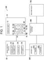
- FIG. 1 is a block diagram showing a construction machine 100 according to the first embodiment of the present invention.
- the construction machine 100 has a display device 10, a main control device 20, an engine unit 500, a hydraulic system 600, and a machine body 700.
- the hydraulic system 600 includes, for example, a hydraulic pump and a hydraulic circuit.
- the machine body 700 includes a run body and a work machine.
- the hydraulic system 600 by the power generated by the engine unit 500, supplies a hydraulic oil to the machine body 700.
- the run body and work machine of the machine body 700 operate.
- the construction machine 100 is, for example, a hydraulic excavator.
- the display device 10 is provided with a display unit 12 and an operation unit 14.
- the display unit 12 includes, for example, a liquid crystal display or an organic electroluminescent display.
- the display unit 12 displays an image. Specifically, the display unit 12 displays a given display screen.
- the display unit 12 corresponds to an example of a "notification unit” and a "display section".
- the operation unit 14 is placed around the display unit 12, for example, receives an operation of a human operator, and outputs an operation signal that corresponds to the operation of the human operator.
- This operation unit 14 has at least one operant 16 composed of a push button, for example, and in the present embodiment, six operants 16.
- the operation unit 14 having the above configuration outputs an operation signal showing whether or not the operant 16 was operated by the human operator.
- the plurality of operants 16 are described as operants 16A, 16B, 16C, 16D, 16E, and 16F, respectively.
- the main control device 20 includes an ECU (Electronic Control Unit), for example, and is provided with a control unit 22, a storage unit 24, and a measurement unit 26.
- ECU Electronic Control Unit
- the control unit 22 includes a processor such as a CPU (Central Processing Unit).
- the control unit 22 includes a comparison unit 221. Specifically, the processor of the control unit 22 executes a computer program stored in the storage unit 24, thereby functioning as the comparison unit 221.
- the storage unit 24 includes a storage device that stores various data and computer programs. This storage unit 24 stores, as various data, setting information preliminarily entered by the human operator, information on the number of drives of a starter 520 (to be described below), and information on a reference value for the number of drives of the starter 520, for example.
- the control unit 22 controls the entirety of the construction machine 100, and when a state of no operation by the human operator (no operation state) elapses for a preset setting time, executes an automatic engine stop control to stop the engine 510.
- This setting time can be set between "5 minutes” and " 1 hour", for example.
- the engine 510 is described below.
- control unit 22 of the present embodiment executes the automatic engine stop control based on the number of drives and the reference value, and when the number of drives reaches the reference value, the automatic stop time is extended or the automatic engine stop control is disabled.
- the automatic stop time shows the time from the no operation state until the time when the engine 510 is automatically stopped by the automatic engine stop control.
- the automatic stop time as the case may be, is described as "automatic stop time Ta".
- control unit 22 causes the display device 10 to execute a given notification process based on the number of drives and the reference value.
- the notification process is described below.
- the construction machine In general, compared with a passenger car, the construction machine, because the operation is so often interrupted during work, is more prone to a situation that results in the automatic engine stop.
- the wear of the starter in the construction machine may be larger than in the passenger car.
- the possibility of the engine start failure increases.
- the construction machine due to its heavy weight, is more difficult to tow than the passenger car.
- the measurement unit 26 measures the number of drives of the starter 520. Specifically, the measurement unit 26, each time a key operation to the construction machine 100 is executed by the human operator, for example, measures the number of drives of the starter 520, and sends a measurement result to the storage unit 24.
- the measurement result is, for example, a cumulative value (number of drives). In the present embodiment, each time the starter 520 is driven once, the measurement unit 26 adds "1" to the accumulated value, for example.
- the storage unit 24 stores the number of drives and the reference value.
- the number of drives is the number of drives of the starter 520 measured by the measurement unit 26.
- the reference value is, for example, a value that shows a reference for the number of drives, and is based on the specification of the starter 520's durability count.
- the engine unit 500 has an engine 510 and the starter 520.
- the engine 510 generates power.
- the starter 520 starts the engine 510.
- the human operator makes the key operation to the construction machine 100, thereby to cause the starter 520 to start the engine 510.
- the comparison unit 221 compares the number of drives with the reference value. Specifically, when the construction machine 100 is in the no operation state, for example, the comparison unit 221 compares the number of drives with the reference value. For example, in response to that the measurement unit 26 measured the number of drives of the starter 520, the comparison unit 221 may compare the number of drives with the reference value.
- the display unit 12 notifies about the drive state of the starter 520 based on the number of drives and the reference value. Further, the display unit 12 can notify about the result of the comparing by the comparison unit 221. In detail, when the number of drives exceeds the reference value, the display unit 12 executes a notification process to notify that the number of drives exceeds the reference value. In more detail, the display unit 12 shows, in the notification process, that the number of drives exceeds the reference value. Further, the screen (notification screen) displayed on the display unit 12 in the notification process is described below.
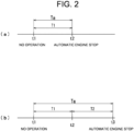
- FIGS. 2(a) and 2(b) illustrate the automatic engine stop function.
- a time t1 shows the time of causing the no operation state.
- a time t2 shows the time of the automatic engine stop.
- the no operation state shows a mode in which no operation is executed on the construction machine 100.
- the no operation state shows, for example, that a cutoff lever that prohibits the operation of the construction machine 100 is lowered (operation enabled state), and that an operation lever for operating the construction machine 100 is not being made.
- the no operation state includes a state in which the cutoff lever is raised (operation disabled state).
- the control unit 22 When the number of drives does not exceed the reference value, the control unit 22, after an elapse of the setting time T1, executes the automatic engine stop control. In detail, after an elapse of the setting time T1, the control unit 22 stops the engine 510. Thus, fuel consumption during the non-work can be suppressed.
- the setting time T1 is equal to the automatic stop time Ta.
- the time t1 shows the time of causing the no operation state.
- the time t2 shows the time when the initial setting time T1 has elapsed from the no operation state.
- a time t3 shows the setting time after extension (setting time T1 + extension time T2), i.e., the time when the engine is automatically stopped.
- control unit 22 is so configured as to be capable of setting the automatic stop time Ta, and based on the result of the comparing by the comparison unit 221, changes the setting time until the automatic engine stop.
- control unit 22 based on the result of the comparing by the comparison unit 221, executes a first automatic engine stop control that changes the automatic stop time Ta.
- the control unit 22 When the number of drives exceeds the reference value, the control unit 22 extends the automatic stop time Ta until the automatic engine stop (extending control of automatic stop time Ta), as shown in FIG. 2(b) .
- the automatic stop time Ta is the time obtained by adding the setting time T1 and the extension time T2.
- the control unit 22 sets the extension time T2 to the same value as the setting time T1, for example.
- the extension time T2 is a time that cannot be set by the human operator. Further, the extension time T2 may be made settable by the human operator.
- control unit 22 may change the extension time T2 according to the number of drives. For example, the control unit 22 may increase the extension time T2 as the number of drives increases. Or, the extension time T2 may be a fixed value.
- the control unit 22 may have a function to control the enabling or disabling of the automatic engine stop function (control of disabling automatic engine stop function).
- the control unit 22 based on the result of the comparing by the comparison unit 221, may disable the automatic engine stop function. More specifically, when the number of drives exceeds the reference value, the control unit 22 may execute a second automatic engine stop control that disables the automatic engine stop function.
- the extending control of the automatic stop time Ta may be combined with the control of disabling the automatic engine stop function. For example, when the number of drives exceeds the reference value, if the subsequent number of drive values is within a given value, the control unit 22 may execute the extending control of the automatic stop time Ta, and if the subsequent number of drive values exceeds the given value, the control unit 22 may execute the disabling control of the automatic engine stop function. In this way, making the automatic engine stop control stepwise can eliminate the engine start failure while ensuring the human operator's convenience.
- FIG. 3 is a flowchart showing an example of the automatic engine stop control process by the control unit 22 according to the first embodiment of the present invention.
- Step S102 The control unit 22 determines whether or not the no operation state is made. When the control unit 22 determines that the no operation is not made (step S102: No), the process waits for a certain time period and returns to step S102 again. When the control unit 22 determines that the no operation is made (step S102: Yes), the process proceeds to step S104.
- Step S104 The control unit 22 determines whether or not the number of drives exceeds the reference value. That is, the comparison unit 221 compares the number of drives with the reference value. When the control unit 22 determines that the number of drives does not exceed the reference value (step S104: No), the process proceeds to step S106. When the control unit 22 determines that the number of drives exceeds the reference value (step S104: Yes), the process proceeds to step S108.
- Step S106 The control unit 22 stops the engine 510 after an elapse of the setting time T1. When this process is ended, the series of automatic engine stop control processes ends.
- Step S108 The control unit 22 stops the engine 510 after an elapse of the setting time T1 + extension time T2. When this process is ended, the series of automatic engine stop control processes ends.
- an extending control process of the automatic stop time is executed in step S108, but otherwise, a disabling control of the automatic engine stop function may also be executed, and in addition to these processes, the notification process may be executed.
- the storage unit 24 stores, as reference values, a first reference value and a second reference value larger than the first reference value.
- the control unit 22 may execute the automatic engine stop controls different between the first reference value and the second reference value. Specifically, the control unit 22 may execute a changing process of the automatic engine stop time based on the result of the comparison with the first reference value, and may execute a disabling process of the automatic engine stop function based on the result of the comparison with the second reference value.
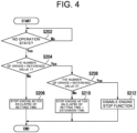
- FIG. 4 is a flowchart showing the other example of the automatic engine stop control process by the control unit 22 according to the first embodiment of the present invention.
- Step S202 The control unit 22 determines whether or not the no operation state is made. When the control unit 22 determines that the no operation state is not made (step S202: No), the process waits for a certain time period and returns to step S202 again. When the control unit 22 determines that the no operation state is made (step S202: Yes), the process proceeds to step S204.
- Step S204 The control unit 22 determines whether or not the number of drives exceeds the first reference value. That is, the comparison unit 221 compares the number of drives with the first reference value. When the control unit 22 determines that the number of drives does not exceed the first reference value (step S204: No), the process proceeds to step S206. When the control unit 22 determines that the number of drives exceeds the first reference value (step S204: Yes), the process proceeds to step S208.
- Step S206 The control unit 22 stops the engine 510 after an elapse of the setting time T1. When this process is ended, the series of automatic engine stop control processes ends.
- Step S208 The control unit 22 determines whether or not the number of drives exceeds the second reference value. That is, the comparison unit 221 compares the number of drives with the second reference value. When the control unit 22 determines that the number of drives does not exceed the second reference value (step S208: No), the process proceeds to step S210. When the control unit 22 determines that the number of drives exceeds the second reference value (step S208: Yes), the process proceeds to step S212.
- Step S210 The control unit 22 stops the engine 510 after an elapse of the setting time T1 + extension time T2. When this process is ended, the series of automatic engine stop control processes ends.
- Step S212 The control unit 22 executes the disabling control of the automatic engine stop function. When this process is ended, the series of automatic engine stop control processes ends.
- the changing process of the automatic engine stop time is executed based on the result of the comparison with the first reference value
- the disabling process of the automatic engine stop function is executed based on the result of the comparison with the second reference value, but not limited thereto.
- the disabling process of the automatic engine stop function may be executed based on the result of the comparison with the first reference value
- the changing process of the automatic engine stop time may be executed based on the result of the comparison with the second reference value.
- FIG. 5 shows the display screen SCA.
- the display screen SCA is a screen that is normally displayed on the display unit 12 after startup of the construction machine 100.
- the display screen SCA includes a display area displaying various information on the construction machine 100 and an operation content display area 46.
- the display area for displaying various information includes a time display area 60 placed on the left side in the upper step of the screen, an error display area 62 placed in the middle in the upper step of the screen, an operation value display area 64 placed on the right side in the upper step of the screen, a fuel information display area 66 placed on the left side in the middle step of the screen, a camera image display area 68 placed in the middle of the screen, an icon display area 70 and a revolution speed display area 72 which are placed on the right side in the middle step of the screen, an option content information display area 74 placed in the lower step of the screen, and the operation content display area 46.
- the operation content display area 46 is a display area that displays the operation content operable by the human operator, and includes, for example, a plurality of selected units 46A to 46F placed on one straight line. These selected units 46A to 46F are displayed in correspondence with the above operants 16A to 16F of the operation unit 14, and operating the operants 16A to 16F that corresponds to the selected units 46A to 46F switches the display content. Further, each of the plural selected units 46A to 46F is an object, for example.
- the operation value display area 64 displays an operation value showing an operation performance of the construction machine 100.
- the operation value is shown as an hour.
- the fuel information display area 66 is a display area showing the state of a remaining fuel oil, and displays, for example, a graphic showing that it is the fuel information display area 66 and a gauge 662 showing the remaining fuel amount by a columnar graph.
- the display unit 12 When the number of drives exceeds the reference value, the display unit 12, using a message, shows that the number of drives has exceeded the reference value. In detail, when the number of drives exceeded the reference value, the display unit 12 displays the message image in the error display area 62.
- the message image is an image showing "The number of drives of starter is exceeding.”, for example.
- the message image may be displayed in the camera image display area 68 other than the error display area 62. Displaying the message image in the camera image display area 68, which is widely distributed in the center of the screen makes it possible to give high degree of caution to the human operator.
- the display unit 12 may show, with the message, that an automatic operation stop function is disabled.
- the display unit 12 displays the message image in the error display area 62.
- the message image is an image showing "The automatic engine stop function is disabled.”, for example.
- the display unit 12 simultaneously with the disabling of the automatic engine stop function, notifies that the automatic engine stop function is disabled.
- the display unit 12 when the number of drives exceeds the reference value, may show, with the message, that the time period until the automatic engine stop is extended.
- the display unit 12 displays the message image in the error display area 62.
- the message image is an image showing "Time period until the automatic engine stop is extended.”, for example. In this way, the display unit 12, simultaneously with the changing of the setting time, notifies that the setting time is changed.
- the display unit 12 may show, using an icon 71, that the number of drives has exceeded the reference value. In detail, when the number of drives exceeds the reference value, the display unit 12 may light or blink the icon 71.
- the display unit 12 when the number of drives has exceeded the reference value, the display unit 12, as a control process, may display a setting screen that allows selection of either changing the automatic engine stop period or disabling the automatic engine stop function.
- FIG. 6 shows the setting screen SCD.
- the setting screen SCD is a screen on which a message image MSG1 is superimposed on the display screen SCA.
- the message image MSG1 is an image showing multiple messages such as "No change in setting”, “Change automatic stop time” and "Disable automatic engine stop function".
- the control unit 22 executes the control process that corresponds to the selected message.
- control unit 22 causes the display unit 12 to display the setting screen SCD which allows selection of the control process, and, depending on the setting operation, executes either changing of the automatic engine stop period or disabling of the automatic engine stop function.
- FIG. 7 is a flowchart showing an example of the automatic engine stop control process that accords to the setting operation by the control unit 22 according to the first embodiment of the present invention.
- Step S302 The control unit 22 determines whether or not the no operation state is made. When the control unit 22 determines that the no operation state is not made (step S302: No), the process waits for a certain time period and returns to step S302 again. When the control unit 22 determines that the no operation state is made (step S302: Yes), the process proceeds to step S304.
- Step S304 The control unit 22 determines whether or not the number of drives exceeds the reference value. That is, the comparison unit 221 compares the number of drives with the reference value. When the control unit 22 determines that the number of drives does not exceed the reference value (step S304: No), the process proceeds to step S306. When the control unit 22 determines that the number of drives exceeds the reference value (step S304: Yes), the process proceeds to step S308.
- Step S306 The control unit 22 stops the engine 510 after an elapse of the setting time T1. When this process is ended, the series of automatic engine stop control processes ends.
- Step S308 The control unit 22 determines the number of times the number of drives exceeds the reference value. When the control unit 22 determines that the number of times the number of drives exceeds the reference value is one time (step S308: Yes), the process proceeds to step S310. When the control unit 22 determines that the number of times the number of drives exceeds the reference value is two or more (step S208: No), the process proceeds to step S312.
- Step S310 The display unit 12 displays the setting screen SCD including two messages. The process proceeds to step S312.
- Step S312 The control unit 22 executes the automatic engine stop control that corresponds to any one of the two messages selected by the human operator.
- step S312: Yes When the human operator selects "Change automatic stop time” (step S312: Yes), the process proceeds to step S314.
- step S312: No When the human operator selects "Change automatic stop time” (step S312: No), the process proceeds to step S316.
- Step S314 The control unit 22 stops the engine 510 after an elapse of the setting time T1 + extension time T2. When this process is ended, the series of automatic engine stop control processes ends.
- Step S316 The control unit 22 executes the disabling control of the automatic engine stop function. When this process is ended, the series of automatic engine stop control processes ends.
- FIG. 8 is a flowchart showing another example of the automatic engine stop control process that accords to the setting operation by the control unit 22 according to the first embodiment of the present invention.
- Step S402 The control unit 22 determines whether or not the no operation state is made. When the control unit 22 determines that the no operation state is not made (step S402: No), the process waits for a certain time period and returns to step S402 again. When the control unit 22 determines that the no operation state is made (step S402: Yes), the process proceeds to step S404.
- Step S404 The control unit 22 determines whether or not the number of drives exceeds the first reference value. That is, the comparison unit 221 compares the number of drives with the first reference value. When the control unit 22 determines that the number of drives does not exceed the first reference value (step S404: No), the process proceeds to step S406. When the control unit 22 determines that the number of drives exceeds the first reference value (step S404: Yes), the process proceeds to step S410.
- Step S406 The display unit 12 displays the setting screen SCD including two messages. The process proceeds to step S408.
- Step S408 The control unit 22 executes the automatic engine stop control that corresponds to any one of the two messages selected by the human operator.
- the control unit 22 stops the engine 510 after an elapse of the setting time T1 + extension time T2.
- the series of automatic engine stop control processes ends.
- the control unit 22 executes the disabling control of the automatic engine stop function.
- the series of automatic engine stop control processes ends.
- Step S410 The control unit 22 determines whether or not the number of drives exceeds the second reference value. That is, the comparison unit 221 compares the number of drives with the second reference value. When the control unit 22 determines that the number of drives does not exceed the second reference value (step S410: No), the process proceeds to step S412. When the control unit 22 determines that the number of drives exceeds the second reference value (step S410: Yes), the process proceeds to step S414.
- Step S412 The control unit 22 stops the engine 510 after an elapse of the setting time T1 + extension time T2. When this process is ended, the series of automatic engine stop control processes ends.
- Step S414 The control unit 22 executes the disabling control of the automatic engine stop function. When this process is ended, the series of automatic engine stop control processes ends.
- FIG. 9 shows the display screen SCB.
- the display screen SCB is a maintenance screen displayed on the display unit 12 by the human operator operating the display device 10, and displays various information on the construction machine 100.
- the display screen SCB includes an item display area 51 and an item state display area 52.
- the item display area 51 displays an image showing an item.
- the item display area 51 includes a first item display area 51A, a second item display area 51B, a third item display area 51C, a fourth item display area 51D, and a fifth item display area 51E.
- the first item display area 51A shows “Engine Oil”.
- the second item display area 51B shows “Engine Oil Filter”.
- the third item display area 51C shows "Hydraulic oil.
- the fourth item display area 51D shows "Hydraulic Oil Return Filter”.
- the fifth item display area 51E shows "Starter”.
- the item state display area 52 displays an image showing the state of the item.
- the item state display area 52 includes a first item state display area 52A, a second item state display area 52B, a third item state display area 52C, a fourth item state display area 52D, and a fifth item state display area 52E.
- the first item state display area 52A, the second item state display area 52B, the third item state display area 52C, the fourth item state display area 52D, and the fifth item state display area 52E correspond to the first item display area 51A, the second item display area 51B, the third item display area 51C, the fourth item display area 51D, and the fifth item display area 51E, respectively.
- “VE x (drives)/VEu, (drives)” is displayed in the fifth item state display area 52E, corresponding to "Starter Drive” displayed in the fifth item display area 51E.
- the display unit 12 has the display screen SCB that can show the number of drives of the starter 520 measured by the measurement unit 26.
- the display unit 12 shows, side by side, at least the current number of drives of the starter 520 and/or the reference value.
- the number of drives is VE x (drives) and the reference value is VE th (drives).
- the display unit 12 notification unit notifies about the drive state of the starter 520 based on the number of drives and the reference value. This allows the human operator to check the drive state of the starter 520. Thus, the starter 520 can be checked for the wear condition. As a result, the possibility of the engine start failure due to excessive wear of the starter 520 can be suppressed.
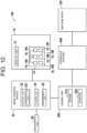
- FIG. 10 is a block diagram showing the construction machine 100 according to the second embodiment of the present invention.
- the construction machine 100 according to the second embodiment excluding having a sound output unit 30, has the same configuration as the construction machine 100 according to the first embodiment; thus, description of duplicated parts is omitted.
- the construction machine 100 is provided with the display device 10, the main control device 20, the engine unit 500, the hydraulic system 600, and the machine body 700, as well as the sound output unit 30.
- the sound output unit 30 corresponds to an example of the "notification unit” and the "notification section.
- the sound output unit 30 is, for example, a speaker or a buzzer. When the number of drives exceeds the reference value, the sound output unit 30 may sound the buzzer, for example. Or, when the number of drives exceeds the reference value, the sound output unit 30 may emit a voice indicating an announcement.
- the sound output unit 30 (notification section), in the notification process, issues the alarm that the number of drives exceeds the reference value.
- the starter 520 can be checked for the wear condition. As a result, the possibility of the engine start failure due to excessive wear of the starter 520 can be suppressed.
- FIGS. 1 to 10 the embodiments of the present invention have been described.
- the present invention is not limited to the embodiments described above, and may be embodied in various modes within a range without departing from its gist.
- the drawings are schematically illustrated with each component as a main subject in order to facilitate understanding, and the thickness, length, number, and the like of each of the illustrated component elements may be different from actual ones due to convenience of the drawings.
- the material, shape, dimension and the like of each of the component elements shown in the above embodiments are each one example are not particularly limited, and may be variously modified within a scope not substantially departing from the effect of the present invention.
Landscapes
- Engineering & Computer Science (AREA)
- General Engineering & Computer Science (AREA)
- Mining & Mineral Resources (AREA)
- Civil Engineering (AREA)
- Structural Engineering (AREA)
- Chemical & Material Sciences (AREA)
- Combustion & Propulsion (AREA)
- Mechanical Engineering (AREA)
- Control Of Vehicle Engines Or Engines For Specific Uses (AREA)
Abstract
Description
- The present invention relates to a construction machine.
- A construction machine having an automatic engine stop function is known (e.g., Patent Literature 1) The construction machine described in
Patent Literature 1 automatically stops an engine on the condition that an operator disembarks. - Patent Literature 1:
Japanese Patent No. 4089270 - However, the construction machine described in
Patent Literature 1, compared with a construction machine without an automatic engine stop function, increases the number of drives of a starter, resulting in an excessive wear of the starter. As a result, the excessive wear of the starter may cause an engine start failure. - The present invention has been made in view of the above problem; it is therefore an object of the present invention to provide a construction machine capable of suppressing a possibility of causing an engine start failure.
- According to an aspect of the present invention, a construction machine includes: a measurement unit, a storage unit, and a notification unit. The measurement unit measures the number of drives of a starter. The storage unit stores the number of drives measured by the measurement unit, and a reference value. The notification unit notifies about a drive state of the starter based on the number of drives and on the reference value.
- According to another aspect of the present invention, a construction machine includes: a measurement unit, a storage unit, and a control unit. The measurement unit measures the number of drives of a starter. The storage unit stores the number of drives measured by the measurement unit, and a reference value. The control unit executes an automatic engine stop control based on the number of drives and on the reference value.
- The present invention can suppress a possibility of causing an engine start failure.
-
-
FIG. 1 is a block diagram showing a construction machine according to a first embodiment of the present invention. -
FIGS. 2(a) and 2(b) illustrate an automatic engine stop function. -
FIG. 3 is a flowchart showing an example of an automatic engine stop control process by a control unit according to a first embodiment of the present invention. -
FIG. 4 is a flowchart showing another example of the automatic engine stop control process by the control unit according to the first embodiment of the present invention. -
FIG. 5 shows a display screen. -
FIG. 6 shows a setting screen. -
FIG. 7 is a flowchart showing an example of the automatic engine stop control process which accords to a setting operation by the control unit according to the first embodiment of the present invention. -
FIG. 8 is a flowchart showing another example of the automatic engine stop control process which accords to the setting operation by the control unit according to the first embodiment of the present invention. -
FIG. 9 shows the display screen. -
FIG. 10 is a block diagram showing the construction machine according to a second embodiment of the present invention. - An embodiment of the present invention will be described hereinafter with reference to the accompanying drawings. It is noted that in the drawings, the same or corresponding parts are denoted by the same reference numerals or signs, and will not be repeatedly described.
- Referring to
FIG. 1 , aconstruction machine 100 according to a first embodiment of the present invention is described.FIG. 1 is a block diagram showing aconstruction machine 100 according to the first embodiment of the present invention. - As shown in
FIG. 1 , theconstruction machine 100 has adisplay device 10, amain control device 20, anengine unit 500, ahydraulic system 600, and amachine body 700. Thehydraulic system 600 includes, for example, a hydraulic pump and a hydraulic circuit. Further, themachine body 700 includes a run body and a work machine. In theabove construction machine 100, thehydraulic system 600, by the power generated by theengine unit 500, supplies a hydraulic oil to themachine body 700. As a result, the run body and work machine of themachine body 700 operate. Theconstruction machine 100 is, for example, a hydraulic excavator. - The
display device 10 is provided with adisplay unit 12 and anoperation unit 14. - The
display unit 12 includes, for example, a liquid crystal display or an organic electroluminescent display. Thedisplay unit 12 displays an image. Specifically, thedisplay unit 12 displays a given display screen. Thedisplay unit 12 corresponds to an example of a "notification unit" and a "display section". - The
operation unit 14 is placed around thedisplay unit 12, for example, receives an operation of a human operator, and outputs an operation signal that corresponds to the operation of the human operator. Thisoperation unit 14 has at least one operant 16 composed of a push button, for example, and in the present embodiment, six operants 16. Theoperation unit 14 having the above configuration outputs an operation signal showing whether or not the operant 16 was operated by the human operator. In the following, when, for explanation, making a distinction among the plural operants 16 of thedisplay device 10, the plurality of operants 16, as the case may be, are described asoperants - The
main control device 20 includes an ECU (Electronic Control Unit), for example, and is provided with acontrol unit 22, astorage unit 24, and ameasurement unit 26. - The
control unit 22 includes a processor such as a CPU (Central Processing Unit). Thecontrol unit 22 includes acomparison unit 221. Specifically, the processor of thecontrol unit 22 executes a computer program stored in thestorage unit 24, thereby functioning as thecomparison unit 221. Thestorage unit 24 includes a storage device that stores various data and computer programs. Thisstorage unit 24 stores, as various data, setting information preliminarily entered by the human operator, information on the number of drives of a starter 520 (to be described below), and information on a reference value for the number of drives of thestarter 520, for example. - The
control unit 22 controls the entirety of theconstruction machine 100, and when a state of no operation by the human operator (no operation state) elapses for a preset setting time, executes an automatic engine stop control to stop theengine 510. This setting time can be set between "5 minutes" and " 1 hour", for example. Theengine 510 is described below. - In particular, the
control unit 22 of the present embodiment executes the automatic engine stop control based on the number of drives and the reference value, and when the number of drives reaches the reference value, the automatic stop time is extended or the automatic engine stop control is disabled. The automatic stop time shows the time from the no operation state until the time when theengine 510 is automatically stopped by the automatic engine stop control. Hereinafter in the present specification, the automatic stop time, as the case may be, is described as "automatic stop time Ta". - Further, the
control unit 22 causes thedisplay device 10 to execute a given notification process based on the number of drives and the reference value. The notification process is described below. - In general, compared with a passenger car, the construction machine, because the operation is so often interrupted during work, is more prone to a situation that results in the automatic engine stop. Thus, the wear of the starter in the construction machine may be larger than in the passenger car. When the starter wears out, the possibility of the engine start failure increases. When the engine does not start, the construction machine, due to its heavy weight, is more difficult to tow than the passenger car. Thus, it is preferable to execute the automatic engine stop control based on the degree of starter wear (number of drives). The automatic engine stop control is described below with reference to
FIGS. 2(a) and 2(b) . - The
measurement unit 26 measures the number of drives of thestarter 520. Specifically, themeasurement unit 26, each time a key operation to theconstruction machine 100 is executed by the human operator, for example, measures the number of drives of thestarter 520, and sends a measurement result to thestorage unit 24. The measurement result is, for example, a cumulative value (number of drives). In the present embodiment, each time thestarter 520 is driven once, themeasurement unit 26 adds "1" to the accumulated value, for example. - The
storage unit 24 stores the number of drives and the reference value. The number of drives is the number of drives of thestarter 520 measured by themeasurement unit 26. The reference value is, for example, a value that shows a reference for the number of drives, and is based on the specification of thestarter 520's durability count. - The
engine unit 500 has anengine 510 and thestarter 520. Theengine 510 generates power. Thestarter 520 starts theengine 510. In detail, the human operator makes the key operation to theconstruction machine 100, thereby to cause thestarter 520 to start theengine 510. - The
comparison unit 221 compares the number of drives with the reference value. Specifically, when theconstruction machine 100 is in the no operation state, for example, thecomparison unit 221 compares the number of drives with the reference value. For example, in response to that themeasurement unit 26 measured the number of drives of thestarter 520, thecomparison unit 221 may compare the number of drives with the reference value. - The
display unit 12 notifies about the drive state of thestarter 520 based on the number of drives and the reference value. Further, thedisplay unit 12 can notify about the result of the comparing by thecomparison unit 221. In detail, when the number of drives exceeds the reference value, thedisplay unit 12 executes a notification process to notify that the number of drives exceeds the reference value. In more detail, thedisplay unit 12 shows, in the notification process, that the number of drives exceeds the reference value. Further, the screen (notification screen) displayed on thedisplay unit 12 in the notification process is described below. - Next, the automatic engine stop function of the
construction machine 100 is described.FIGS. 2(a) and 2(b) illustrate the automatic engine stop function. - First, refer to
FIG. 2(a) , the case in which the number of drives does not exceed the reference value, i.e., a general automatic engine stop function is described. - In
FIG. 2(a) , a time t1 shows the time of causing the no operation state. A time t2 shows the time of the automatic engine stop. - The no operation state shows a mode in which no operation is executed on the
construction machine 100. In detail, the no operation state shows, for example, that a cutoff lever that prohibits the operation of theconstruction machine 100 is lowered (operation enabled state), and that an operation lever for operating theconstruction machine 100 is not being made. Further, the no operation state includes a state in which the cutoff lever is raised (operation disabled state). - When the number of drives does not exceed the reference value, the
control unit 22, after an elapse of the setting time T1, executes the automatic engine stop control. In detail, after an elapse of the setting time T1, thecontrol unit 22 stops theengine 510. Thus, fuel consumption during the non-work can be suppressed. InFIG. 2(a) , the setting time T1 is equal to the automatic stop time Ta. - Next, referring to
FIG. 2(b) , the case in which the number of drives exceeds the reference value, i.e., a characteristic automatic engine stop function of the construction machine is described. - In
FIG. 2(b) , the time t1 shows the time of causing the no operation state. The time t2 shows the time when the initial setting time T1 has elapsed from the no operation state. A time t3 shows the setting time after extension (setting time T1 + extension time T2), i.e., the time when the engine is automatically stopped. - As described above, the
control unit 22 is so configured as to be capable of setting the automatic stop time Ta, and based on the result of the comparing by thecomparison unit 221, changes the setting time until the automatic engine stop. In other words, thecontrol unit 22, based on the result of the comparing by thecomparison unit 221, executes a first automatic engine stop control that changes the automatic stop time Ta. - When the number of drives exceeds the reference value, the
control unit 22 extends the automatic stop time Ta until the automatic engine stop (extending control of automatic stop time Ta), as shown inFIG. 2(b) . In detail, the automatic stop time Ta is the time obtained by adding the setting time T1 and the extension time T2. InFIG. 2(b) , thecontrol unit 22 sets the extension time T2 to the same value as the setting time T1, for example. Further, the extension time T2 is a time that cannot be set by the human operator. Further, the extension time T2 may be made settable by the human operator. When the number of drives exceeds the reference value, i.e., when thestarter 520 is worn out, extending the automatic stop time Ta until the automatic engine stop reduces the number of times the engine automatically stops, as a result, suppresses the excessive wear of thestarter 520, making it possible to suppress the possibility of causing the engine start failure. - Further, the
control unit 22 may change the extension time T2 according to the number of drives. For example, thecontrol unit 22 may increase the extension time T2 as the number of drives increases. Or, the extension time T2 may be a fixed value. - The
control unit 22 may have a function to control the enabling or disabling of the automatic engine stop function (control of disabling automatic engine stop function). In detail, thecontrol unit 22, based on the result of the comparing by thecomparison unit 221, may disable the automatic engine stop function. More specifically, when the number of drives exceeds the reference value, thecontrol unit 22 may execute a second automatic engine stop control that disables the automatic engine stop function. - Further, the extending control of the automatic stop time Ta may be combined with the control of disabling the automatic engine stop function. For example, when the number of drives exceeds the reference value, if the subsequent number of drive values is within a given value, the
control unit 22 may execute the extending control of the automatic stop time Ta, and if the subsequent number of drive values exceeds the given value, thecontrol unit 22 may execute the disabling control of the automatic engine stop function. In this way, making the automatic engine stop control stepwise can eliminate the engine start failure while ensuring the human operator's convenience. - Next, referring to
FIGS. 1 and3 , an automatic engine stop control process by thecontrol unit 22 according to the first embodiment of the present invention is described.FIG. 3 is a flowchart showing an example of the automatic engine stop control process by thecontrol unit 22 according to the first embodiment of the present invention. - Step S102: The
control unit 22 determines whether or not the no operation state is made. When thecontrol unit 22 determines that the no operation is not made (step S102: No), the process waits for a certain time period and returns to step S102 again. When thecontrol unit 22 determines that the no operation is made (step S102: Yes), the process proceeds to step S104. - Step S104: The
control unit 22 determines whether or not the number of drives exceeds the reference value. That is, thecomparison unit 221 compares the number of drives with the reference value. When thecontrol unit 22 determines that the number of drives does not exceed the reference value (step S104: No), the process proceeds to step S106. When thecontrol unit 22 determines that the number of drives exceeds the reference value (step S104: Yes), the process proceeds to step S108. - Step S106: The
control unit 22 stops theengine 510 after an elapse of the setting time T1. When this process is ended, the series of automatic engine stop control processes ends. - Step S108: The
control unit 22 stops theengine 510 after an elapse of the setting time T1 + extension time T2. When this process is ended, the series of automatic engine stop control processes ends. - In the example in
FIG. 3 , an extending control process of the automatic stop time is executed in step S108, but otherwise, a disabling control of the automatic engine stop function may also be executed, and in addition to these processes, the notification process may be executed. - For example, the
storage unit 24 stores, as reference values, a first reference value and a second reference value larger than the first reference value. Thecontrol unit 22 may execute the automatic engine stop controls different between the first reference value and the second reference value. Specifically, thecontrol unit 22 may execute a changing process of the automatic engine stop time based on the result of the comparison with the first reference value, and may execute a disabling process of the automatic engine stop function based on the result of the comparison with the second reference value. - Next, referring to
FIG. 4 , another example of the automatic engine stop control process by thecontrol unit 22 according to the first embodiment of the present invention is described.FIG. 4 is a flowchart showing the other example of the automatic engine stop control process by thecontrol unit 22 according to the first embodiment of the present invention. - Step S202: The
control unit 22 determines whether or not the no operation state is made. When thecontrol unit 22 determines that the no operation state is not made (step S202: No), the process waits for a certain time period and returns to step S202 again. When thecontrol unit 22 determines that the no operation state is made (step S202: Yes), the process proceeds to step S204. - Step S204: The
control unit 22 determines whether or not the number of drives exceeds the first reference value. That is, thecomparison unit 221 compares the number of drives with the first reference value. When thecontrol unit 22 determines that the number of drives does not exceed the first reference value (step S204: No), the process proceeds to step S206. When thecontrol unit 22 determines that the number of drives exceeds the first reference value (step S204: Yes), the process proceeds to step S208. - Step S206: The
control unit 22 stops theengine 510 after an elapse of the setting time T1. When this process is ended, the series of automatic engine stop control processes ends. - Step S208: The
control unit 22 determines whether or not the number of drives exceeds the second reference value. That is, thecomparison unit 221 compares the number of drives with the second reference value. When thecontrol unit 22 determines that the number of drives does not exceed the second reference value (step S208: No), the process proceeds to step S210. When thecontrol unit 22 determines that the number of drives exceeds the second reference value (step S208: Yes), the process proceeds to step S212. - Step S210: The
control unit 22 stops theengine 510 after an elapse of the setting time T1 + extension time T2. When this process is ended, the series of automatic engine stop control processes ends. - Step S212: The
control unit 22 executes the disabling control of the automatic engine stop function. When this process is ended, the series of automatic engine stop control processes ends. - Further, in the example in
FIG. 4 , the changing process of the automatic engine stop time is executed based on the result of the comparison with the first reference value, and the disabling process of the automatic engine stop function is executed based on the result of the comparison with the second reference value, but not limited thereto. For example, the disabling process of the automatic engine stop function may be executed based on the result of the comparison with the first reference value, and the changing process of the automatic engine stop time may be executed based on the result of the comparison with the second reference value. - Next, the notification process by the
display unit 12 is described. A display screen SCA displayed on thedisplay unit 12 is described with reference toFIG. 5. FIG. 5 shows the display screen SCA. The display screen SCA is a screen that is normally displayed on thedisplay unit 12 after startup of theconstruction machine 100. - As shown in
FIG. 5 , the display screen SCA includes a display area displaying various information on theconstruction machine 100 and an operationcontent display area 46. - The display area for displaying various information includes a
time display area 60 placed on the left side in the upper step of the screen, anerror display area 62 placed in the middle in the upper step of the screen, an operationvalue display area 64 placed on the right side in the upper step of the screen, a fuelinformation display area 66 placed on the left side in the middle step of the screen, a cameraimage display area 68 placed in the middle of the screen, anicon display area 70 and a revolutionspeed display area 72 which are placed on the right side in the middle step of the screen, an option contentinformation display area 74 placed in the lower step of the screen, and the operationcontent display area 46. - The operation
content display area 46 is a display area that displays the operation content operable by the human operator, and includes, for example, a plurality of selectedunits 46A to 46F placed on one straight line. These selectedunits 46A to 46F are displayed in correspondence with theabove operants 16A to 16F of theoperation unit 14, and operating theoperants 16A to 16F that corresponds to the selectedunits 46A to 46F switches the display content. Further, each of the plural selectedunits 46A to 46F is an object, for example. - The operation
value display area 64 displays an operation value showing an operation performance of theconstruction machine 100. In the present embodiment, the operation value is shown as an hour. - The fuel
information display area 66 is a display area showing the state of a remaining fuel oil, and displays, for example, a graphic showing that it is the fuelinformation display area 66 and agauge 662 showing the remaining fuel amount by a columnar graph. - When the number of drives exceeds the reference value, the
display unit 12, using a message, shows that the number of drives has exceeded the reference value. In detail, when the number of drives exceeded the reference value, thedisplay unit 12 displays the message image in theerror display area 62. The message image is an image showing "The number of drives of starter is exceeding.", for example. - Further, the message image may be displayed in the camera
image display area 68 other than theerror display area 62. Displaying the message image in the cameraimage display area 68, which is widely distributed in the center of the screen makes it possible to give high degree of caution to the human operator. - Further, when the number of drives exceeds the reference value, the
display unit 12 may show, with the message, that an automatic operation stop function is disabled. In detail, when the automatic operation stop function is disabled in the case of the number of drives exceeding the reference value, thedisplay unit 12 displays the message image in theerror display area 62. The message image is an image showing "The automatic engine stop function is disabled.", for example. Thus, thedisplay unit 12, simultaneously with the disabling of the automatic engine stop function, notifies that the automatic engine stop function is disabled. - Further, the
display unit 12, when the number of drives exceeds the reference value, may show, with the message, that the time period until the automatic engine stop is extended. In detail, when the period until the automatic engine stop is extended in the case of the number of drives exceeding the reference value, thedisplay unit 12 displays the message image in theerror display area 62. The message image is an image showing "Time period until the automatic engine stop is extended.", for example. In this way, thedisplay unit 12, simultaneously with the changing of the setting time, notifies that the setting time is changed. - Further, when the number of drives has exceeded the reference value, the
display unit 12 may show, using anicon 71, that the number of drives has exceeded the reference value. In detail, when the number of drives exceeds the reference value, thedisplay unit 12 may light or blink theicon 71. - Further, when the number of drives has exceeded the reference value, the
display unit 12, as a control process, may display a setting screen that allows selection of either changing the automatic engine stop period or disabling the automatic engine stop function. - Then, a setting screen SCD displayed on the
display unit 12 is described with reference toFIG. 6. FIG. 6 shows the setting screen SCD. The setting screen SCD is a screen on which a message image MSG1 is superimposed on the display screen SCA. The message image MSG1 is an image showing multiple messages such as "No change in setting", "Change automatic stop time" and "Disable automatic engine stop function". When the human operator selects any one of the multiple messages, thecontrol unit 22 executes the control process that corresponds to the selected message. - That is, when the number of drives exceeds the reference value, the
control unit 22 causes thedisplay unit 12 to display the setting screen SCD which allows selection of the control process, and, depending on the setting operation, executes either changing of the automatic engine stop period or disabling of the automatic engine stop function. - Next, referring to
FIG. 7 , an example of the automatic engine stop control process that accords to the setting operation by thecontrol unit 22 according to the first embodiment of the present invention is described.FIG. 7 is a flowchart showing an example of the automatic engine stop control process that accords to the setting operation by thecontrol unit 22 according to the first embodiment of the present invention. - Step S302: The
control unit 22 determines whether or not the no operation state is made. When thecontrol unit 22 determines that the no operation state is not made (step S302: No), the process waits for a certain time period and returns to step S302 again. When thecontrol unit 22 determines that the no operation state is made (step S302: Yes), the process proceeds to step S304. - Step S304: The
control unit 22 determines whether or not the number of drives exceeds the reference value. That is, thecomparison unit 221 compares the number of drives with the reference value. When thecontrol unit 22 determines that the number of drives does not exceed the reference value (step S304: No), the process proceeds to step S306. When thecontrol unit 22 determines that the number of drives exceeds the reference value (step S304: Yes), the process proceeds to step S308. - Step S306: The
control unit 22 stops theengine 510 after an elapse of the setting time T1. When this process is ended, the series of automatic engine stop control processes ends. - Step S308: The
control unit 22 determines the number of times the number of drives exceeds the reference value. When thecontrol unit 22 determines that the number of times the number of drives exceeds the reference value is one time (step S308: Yes), the process proceeds to step S310. When thecontrol unit 22 determines that the number of times the number of drives exceeds the reference value is two or more (step S208: No), the process proceeds to step S312. - Step S310: The
display unit 12 displays the setting screen SCD including two messages. The process proceeds to step S312. - Step S312: The
control unit 22 executes the automatic engine stop control that corresponds to any one of the two messages selected by the human operator. When the human operator selects "Change automatic stop time" (step S312: Yes), the process proceeds to step S314. When the human operator selects "Change automatic stop time" (step S312: No), the process proceeds to step S316. - Step S314: The
control unit 22 stops theengine 510 after an elapse of the setting time T1 + extension time T2. When this process is ended, the series of automatic engine stop control processes ends. - Step S316: The
control unit 22 executes the disabling control of the automatic engine stop function. When this process is ended, the series of automatic engine stop control processes ends. - Next, with reference to
FIG. 8 , another example of the automatic engine stop control process that accords to the setting operation by thecontrol unit 22 according to the first embodiment of the present invention is described.FIG. 8 is a flowchart showing another example of the automatic engine stop control process that accords to the setting operation by thecontrol unit 22 according to the first embodiment of the present invention. - Step S402: The
control unit 22 determines whether or not the no operation state is made. When thecontrol unit 22 determines that the no operation state is not made (step S402: No), the process waits for a certain time period and returns to step S402 again. When thecontrol unit 22 determines that the no operation state is made (step S402: Yes), the process proceeds to step S404. - Step S404: The
control unit 22 determines whether or not the number of drives exceeds the first reference value. That is, thecomparison unit 221 compares the number of drives with the first reference value. When thecontrol unit 22 determines that the number of drives does not exceed the first reference value (step S404: No), the process proceeds to step S406. When thecontrol unit 22 determines that the number of drives exceeds the first reference value (step S404: Yes), the process proceeds to step S410. - Step S406: The
display unit 12 displays the setting screen SCD including two messages. The process proceeds to step S408. - Step S408: The
control unit 22 executes the automatic engine stop control that corresponds to any one of the two messages selected by the human operator. When the human operator selects "Change automatic stop time", thecontrol unit 22 stops theengine 510 after an elapse of the setting time T1 + extension time T2. When this process is ended, the series of automatic engine stop control processes ends. Meanwhile, when the human operator selects "Disable automatic engine stop function", thecontrol unit 22 executes the disabling control of the automatic engine stop function. When this process is ended, the series of automatic engine stop control processes ends. - Step S410: The
control unit 22 determines whether or not the number of drives exceeds the second reference value. That is, thecomparison unit 221 compares the number of drives with the second reference value. When thecontrol unit 22 determines that the number of drives does not exceed the second reference value (step S410: No), the process proceeds to step S412. When thecontrol unit 22 determines that the number of drives exceeds the second reference value (step S410: Yes), the process proceeds to step S414. - Step S412: The
control unit 22 stops theengine 510 after an elapse of the setting time T1 + extension time T2. When this process is ended, the series of automatic engine stop control processes ends. - Step S414: The
control unit 22 executes the disabling control of the automatic engine stop function. When this process is ended, the series of automatic engine stop control processes ends. - Next, a display screen SCB displayed on the
display unit 12 is described with reference toFIG. 9. FIG. 9 shows the display screen SCB. The display screen SCB is a maintenance screen displayed on thedisplay unit 12 by the human operator operating thedisplay device 10, and displays various information on theconstruction machine 100. - As shown in
FIG. 9 , the display screen SCB includes an item display area 51 and an itemstate display area 52. - The item display area 51 displays an image showing an item. The item display area 51 includes a first
item display area 51A, a seconditem display area 51B, a third item display area 51C, a fourthitem display area 51D, and a fifthitem display area 51E. - The first
item display area 51A shows "Engine Oil". The seconditem display area 51B shows "Engine Oil Filter". The third item display area 51C shows "Hydraulic oil. The fourthitem display area 51D shows "Hydraulic Oil Return Filter". The fifthitem display area 51E shows "Starter". - The item
state display area 52 displays an image showing the state of the item. The itemstate display area 52 includes a first itemstate display area 52A, a second itemstate display area 52B, a third itemstate display area 52C, a fourth itemstate display area 52D, and a fifth itemstate display area 52E. - The first item
state display area 52A, the second itemstate display area 52B, the third itemstate display area 52C, the fourth itemstate display area 52D, and the fifth itemstate display area 52E correspond to the firstitem display area 51A, the seconditem display area 51B, the third item display area 51C, the fourthitem display area 51D, and the fifthitem display area 51E, respectively. For example, "VEx (drives)/VEu, (drives)" is displayed in the fifth itemstate display area 52E, corresponding to "Starter Drive" displayed in the fifthitem display area 51E. Thus, thedisplay unit 12 has the display screen SCB that can show the number of drives of thestarter 520 measured by themeasurement unit 26. On the display screen SCB, thedisplay unit 12 shows, side by side, at least the current number of drives of thestarter 520 and/or the reference value. Here, the number of drives is VEx (drives) and the reference value is VEth (drives). - As described above with reference to
FIGS. 1 through 9 , the display unit 12 (notification unit) notifies about the drive state of thestarter 520 based on the number of drives and the reference value. This allows the human operator to check the drive state of thestarter 520. Thus, thestarter 520 can be checked for the wear condition. As a result, the possibility of the engine start failure due to excessive wear of thestarter 520 can be suppressed. - Next, referring to
FIG. 10 , theconstruction machine 100 according to a second embodiment of the present invention is described in detail.FIG. 10 is a block diagram showing theconstruction machine 100 according to the second embodiment of the present invention. Theconstruction machine 100 according to the second embodiment, excluding having asound output unit 30, has the same configuration as theconstruction machine 100 according to the first embodiment; thus, description of duplicated parts is omitted. - As shown in
FIG. 10 , theconstruction machine 100 is provided with thedisplay device 10, themain control device 20, theengine unit 500, thehydraulic system 600, and themachine body 700, as well as thesound output unit 30. Thesound output unit 30 corresponds to an example of the "notification unit" and the "notification section. - The
sound output unit 30, in the notification process, issues an alarm that the number of drives has exceeded the reference value. Thesound output unit 30 is, for example, a speaker or a buzzer. When the number of drives exceeds the reference value, thesound output unit 30 may sound the buzzer, for example. Or, when the number of drives exceeds the reference value, thesound output unit 30 may emit a voice indicating an announcement. - As described with reference to
FIG. 10 , the sound output unit 30 (notification section), in the notification process, issues the alarm that the number of drives exceeds the reference value. Thus, thestarter 520 can be checked for the wear condition. As a result, the possibility of the engine start failure due to excessive wear of thestarter 520 can be suppressed. - Referring to
FIGS. 1 to 10 , the embodiments of the present invention have been described. However, the present invention is not limited to the embodiments described above, and may be embodied in various modes within a range without departing from its gist. The drawings are schematically illustrated with each component as a main subject in order to facilitate understanding, and the thickness, length, number, and the like of each of the illustrated component elements may be different from actual ones due to convenience of the drawings. Further, the material, shape, dimension and the like of each of the component elements shown in the above embodiments are each one example are not particularly limited, and may be variously modified within a scope not substantially departing from the effect of the present invention. -
- 12 display unit (notification unit, notification section)
- 22 control unit
- 24 storage unit
- 26 measurement unit
- 30 sound output unit (notification unit, notification section)
- 71 icon
- 100 construction machine
- 221 comparison unit
- 520 starter
- SCD setting screen
Claims (18)
- A construction machine comprising:a measurement unit that measures the number of drives of a starter;a storage unit that stores the number of drives measured by the measurement unit, and a reference value; anda notification unit that executes a notification process to notify about a drive state of the starter based on the number of drives and on the reference value.
- The construction machine as claimed in claim 1, further comprising:
a comparison unit that compares the number of drives with the reference value, wherein
the notification unit, in the notification process, notifies about a result of the comparing by the comparison unit. - The construction machine as claimed in claim 2, wherein
when the number of drives exceeds the reference value as a result of the comparing by the comparison unit, the notification unit, in the notification process, notifies that the number of drives exceeds the reference value. - The construction machine as claimed in claim 3, whereinthe notification unit has a display section, andthe display section, in the notification process, displays that the number of drives exceeds the reference value.
- The construction machine as claimed in claim 4, wherein
the display section, using a message, displays that the number of drives has exceeded the reference value. - The construction machine as claimed in claim 4 or claim 5, wherein
the display section, using an icon, displays that the number of drives exceeds the reference value. - The construction machine as claimed in claim 3, whereinthe notification unit has a notification section, andthe notification section, in the notification process, issues an alarm that the number of drives exceeds the reference value.
- The construction machine as claimed in any one of claims 2 to 7, further comprising:
a control unit that executes an automatic engine stop control. - The construction machine as claimed in claim 8, whereinthe control unit is so configured as to be capable of setting an automatic stop time that shows a time until the automatic engine stop, andthe control unit, based on the result of the comparing by the comparison unit, executes a first automatic engine stop control that changes the automatic stop time.
- The construction machine as claimed in claim 9, wherein
the notification unit, simultaneously with the changing of the automatic stop time, notifies that the automatic stop time is changed. - The construction machine as claimed in claim 8, whereinthe control unit has a function to control enabling or disabling of an automatic engine stop function, andthe control unit, based on the result of the comparing by the comparison unit, executes a second automatic engine stop control that disables the automatic engine stop function.
- The construction machine as claimed in claim 11, wherein
the notification unit, simultaneously with the disabling of the automatic engine stop function, notifies that the automatic engine stop function is disabled. - The construction machine as claimed in claim 11 or claim 12, whereinthe notification unit has a display section, andthe display section, based on the result of the comparing by the comparison unit, displays a setting screen capable of setting content of the automatic engine stop control.
- The construction machine as claimed in claim 11 or claim 12, whereinthe storage unit stores, as the reference values, a first reference value and a second reference value larger than the first reference value, andthe control unitexecutes the first automatic engine stop control based on the number of drives and any one of the first reference value and the second reference value, andexecutes the second automatic engine stop control based on the number of drives and the other of the first reference value and the second reference value.
- A construction machine comprising:a measurement unit that measures the number of drives of a starter;a storage unit that stores the number of drives measured by the measurement unit, and a reference value; anda control unit that executes an automatic engine stop control based on the number of drives and on the reference value.
- The construction machine as claimed in claim 15, whereinthe control unit is so configured as to be capable of setting an automatic stop time that shows a time until the automatic engine stop, andthe control unit, based on the number of drives and the reference value, executes a first automatic engine stop control that changes the automatic stop time.
- The construction machine as claimed in claim 15, whereinthe control unit has a function to control enabling or disabling of an automatic engine stop function, andthe control unit, based on the number of drives and the reference value, executes a second automatic engine stop control that disables the automatic engine stop function.
- The construction machine as claimed in claim 17, whereinthe storage unit stores, as the reference values, a first reference value and a second reference value larger than the first reference value, andthe control unitexecutes the first automatic engine stop control based the number of drives and any one of the first reference value and the second reference value, andexecutes the second automatic engine stop control based on the number of drives and the other of the first reference value and the second reference value.
Applications Claiming Priority (2)
| Application Number | Priority Date | Filing Date | Title |
|---|---|---|---|
| JP2020210239 | 2020-12-18 | ||
| PCT/JP2021/046794 WO2022131368A1 (en) | 2020-12-18 | 2021-12-17 | Construction machine |
Publications (2)
| Publication Number | Publication Date |
|---|---|
| EP4265856A1 true EP4265856A1 (en) | 2023-10-25 |
| EP4265856A4 EP4265856A4 (en) | 2024-11-13 |
Family
ID=82059569
Family Applications (1)
| Application Number | Title | Priority Date | Filing Date |
|---|---|---|---|
| EP21906726.1A Withdrawn EP4265856A4 (en) | 2020-12-18 | 2021-12-17 | Construction machine |
Country Status (6)
| Country | Link |
|---|---|
| US (1) | US20230417027A1 (en) |
| EP (1) | EP4265856A4 (en) |
| JP (1) | JPWO2022131368A1 (en) |
| KR (1) | KR20230118832A (en) |
| CN (1) | CN116745492A (en) |
| WO (1) | WO2022131368A1 (en) |
Family Cites Families (14)
| Publication number | Priority date | Publication date | Assignee | Title |
|---|---|---|---|---|
| JP2002021690A (en) * | 2000-07-05 | 2002-01-23 | Isuzu Motors Ltd | Engine automatic stop and start device |
| JP4089270B2 (en) | 2002-04-15 | 2008-05-28 | コベルコ建機株式会社 | Construction machine and engine control method thereof |
| JP4114486B2 (en) * | 2003-01-15 | 2008-07-09 | マツダ株式会社 | Vehicle engine control device |
| US20060200292A1 (en) * | 2003-01-31 | 2006-09-07 | Obelco Construction Machinery Co., Ltd. | Engine control device for and administration system for contruction machine |
| JP4694895B2 (en) * | 2005-06-07 | 2011-06-08 | 日立建機株式会社 | Construction machinery |
| JP2008019716A (en) * | 2006-07-10 | 2008-01-31 | Mazda Motor Corp | Electronic control device for vehicle |
| DE102009018974B4 (en) * | 2009-04-25 | 2019-07-18 | Bayerische Motoren Werke Aktiengesellschaft | Control unit for controlling a switch-on of a drive unit in a motor vehicle |
| JP2012127237A (en) * | 2010-12-14 | 2012-07-05 | Fuji Heavy Ind Ltd | Idle stop control system for vehicle |
| JP2013060856A (en) * | 2011-09-13 | 2013-04-04 | Toyota Motor Corp | Vehicle control device |
| EP2808453B1 (en) * | 2012-01-25 | 2017-06-28 | Hitachi Construction Machinery Tierra Co., Ltd. | Construction machine |
| JP2014019417A (en) * | 2012-07-24 | 2014-02-03 | Toyota Motor Corp | Control device for hybrid power apparatus |
| IN2015DN06419A (en) * | 2013-07-22 | 2015-07-31 | Komatsu Mfg Co Ltd | |
| EP3313700B1 (en) * | 2015-06-29 | 2025-01-01 | Cummins, Inc. | Managing automatic stop/start frequency |
| WO2018063251A1 (en) * | 2016-09-29 | 2018-04-05 | Cummins Inc. | Systems and methods for accommodating loss of battery charge history |
-
2021
- 2021-12-17 JP JP2022570079A patent/JPWO2022131368A1/ja active Pending
- 2021-12-17 EP EP21906726.1A patent/EP4265856A4/en not_active Withdrawn
- 2021-12-17 KR KR1020237018796A patent/KR20230118832A/en not_active Withdrawn
- 2021-12-17 CN CN202180084577.3A patent/CN116745492A/en active Pending
- 2021-12-17 US US18/037,035 patent/US20230417027A1/en not_active Abandoned
- 2021-12-17 WO PCT/JP2021/046794 patent/WO2022131368A1/en not_active Ceased
Also Published As
| Publication number | Publication date |
|---|---|
| CN116745492A (en) | 2023-09-12 |
| EP4265856A4 (en) | 2024-11-13 |
| KR20230118832A (en) | 2023-08-14 |
| JPWO2022131368A1 (en) | 2022-06-23 |
| US20230417027A1 (en) | 2023-12-28 |
| WO2022131368A1 (en) | 2022-06-23 |
Similar Documents
| Publication | Publication Date | Title |
|---|---|---|
| DE112014000084B4 (en) | Display device of a work machine, display method thereof and work vehicle | |
| US20140189585A1 (en) | Information Display System for a Machine | |
| US9546470B2 (en) | Screen display method of wheel loader | |
| US20050038573A1 (en) | Vehicle information/task manager | |
| US20160358496A1 (en) | Virtual trainer for in vehicle driver coaching and to collect metrics to improve driver performance | |
| JP4564452B2 (en) | Plant monitoring device | |
| DE112014000048B4 (en) | A urea water supply prompt output device for a work vehicle and a urea water supply prompt output method for a work vehicle | |
| CN113676508A (en) | System and method for real-time health monitoring of machine components | |
| DE112013007259T5 (en) | working vehicle | |
| US20210123217A1 (en) | Maintenance assistance device, work machine, maintenance assistance system, and maintenance assistance method | |
| JP7675521B2 (en) | Battery level prediction system | |
| JP6571440B2 (en) | Working vehicle | |
| US20230417027A1 (en) | Construction Machine | |
| JP2010179783A (en) | Vehicle information reporting device | |
| US20250043544A1 (en) | Actual machine management device, and actual machine management system | |
| JP2017029107A (en) | Working vehicle | |
| JP4264733B2 (en) | Construction machine display device | |
| EP3525051B1 (en) | Monitoring device and method of monitoring | |
| CN109991540B (en) | Unmanned aerial vehicle with power monitoring function | |
| CN111289036A (en) | Equipment fault early warning method, device, equipment and system | |
| EP4286608A1 (en) | Display device and work machine | |
| US20070078615A1 (en) | Method and device for communication with a plant | |
| CN112706933A (en) | System and method for determining and displaying automatic flight approach and landing capability | |
| JP6571439B2 (en) | Working vehicle | |
| CN112412648A (en) | Power matching self-adaptive control method, device, equipment and storage medium |
Legal Events
| Date | Code | Title | Description |
|---|---|---|---|
| STAA | Information on the status of an ep patent application or granted ep patent |
Free format text: STATUS: THE INTERNATIONAL PUBLICATION HAS BEEN MADE |
|
| PUAI | Public reference made under article 153(3) epc to a published international application that has entered the european phase |
Free format text: ORIGINAL CODE: 0009012 |
|
| STAA | Information on the status of an ep patent application or granted ep patent |
Free format text: STATUS: REQUEST FOR EXAMINATION WAS MADE |
|
| 17P | Request for examination filed |
Effective date: 20230601 |
|
| AK | Designated contracting states |
Kind code of ref document: A1 Designated state(s): AL AT BE BG CH CY CZ DE DK EE ES FI FR GB GR HR HU IE IS IT LI LT LU LV MC MK MT NL NO PL PT RO RS SE SI SK SM TR |
|
| DAV | Request for validation of the european patent (deleted) | ||
| DAX | Request for extension of the european patent (deleted) | ||
| A4 | Supplementary search report drawn up and despatched |
Effective date: 20241015 |
|
| RIC1 | Information provided on ipc code assigned before grant |
Ipc: F02N 11/08 20060101ALI20241009BHEP Ipc: E02F 9/26 20060101ALI20241009BHEP Ipc: F02D 29/02 20060101ALI20241009BHEP Ipc: F02D 29/00 20060101ALI20241009BHEP Ipc: E02F 9/20 20060101AFI20241009BHEP |
|
| STAA | Information on the status of an ep patent application or granted ep patent |
Free format text: STATUS: THE APPLICATION IS DEEMED TO BE WITHDRAWN |
|
| 18D | Application deemed to be withdrawn |
Effective date: 20250507 |