EP4265854A1 - Electric work machine - Google Patents
Electric work machine Download PDFInfo
- Publication number
- EP4265854A1 EP4265854A1 EP23166358.4A EP23166358A EP4265854A1 EP 4265854 A1 EP4265854 A1 EP 4265854A1 EP 23166358 A EP23166358 A EP 23166358A EP 4265854 A1 EP4265854 A1 EP 4265854A1
- Authority
- EP
- European Patent Office
- Prior art keywords
- battery unit
- lower plate
- coupling member
- work machine
- battery
- Prior art date
- Legal status (The legal status is an assumption and is not a legal conclusion. Google has not performed a legal analysis and makes no representation as to the accuracy of the status listed.)
- Pending
Links
Images



Classifications
-
- E—FIXED CONSTRUCTIONS
- E02—HYDRAULIC ENGINEERING; FOUNDATIONS; SOIL SHIFTING
- E02F—DREDGING; SOIL-SHIFTING
- E02F9/00—Component parts of dredgers or soil-shifting machines, not restricted to one of the kinds covered by groups E02F3/00 - E02F7/00
- E02F9/08—Superstructures; Supports for superstructures
-
- B—PERFORMING OPERATIONS; TRANSPORTING
- B60—VEHICLES IN GENERAL
- B60K—ARRANGEMENT OR MOUNTING OF PROPULSION UNITS OR OF TRANSMISSIONS IN VEHICLES; ARRANGEMENT OR MOUNTING OF PLURAL DIVERSE PRIME-MOVERS IN VEHICLES; AUXILIARY DRIVES FOR VEHICLES; INSTRUMENTATION OR DASHBOARDS FOR VEHICLES; ARRANGEMENTS IN CONNECTION WITH COOLING, AIR INTAKE, GAS EXHAUST OR FUEL SUPPLY OF PROPULSION UNITS IN VEHICLES
- B60K1/00—Arrangement or mounting of electrical propulsion units
- B60K1/04—Arrangement or mounting of electrical propulsion units of the electric storage means for propulsion
-
- E—FIXED CONSTRUCTIONS
- E02—HYDRAULIC ENGINEERING; FOUNDATIONS; SOIL SHIFTING
- E02F—DREDGING; SOIL-SHIFTING
- E02F9/00—Component parts of dredgers or soil-shifting machines, not restricted to one of the kinds covered by groups E02F3/00 - E02F7/00
- E02F9/08—Superstructures; Supports for superstructures
- E02F9/0858—Arrangement of component parts installed on superstructures not otherwise provided for, e.g. electric components, fenders, air-conditioning units
-
- E—FIXED CONSTRUCTIONS
- E02—HYDRAULIC ENGINEERING; FOUNDATIONS; SOIL SHIFTING
- E02F—DREDGING; SOIL-SHIFTING
- E02F9/00—Component parts of dredgers or soil-shifting machines, not restricted to one of the kinds covered by groups E02F3/00 - E02F7/00
- E02F9/20—Drives; Control devices
- E02F9/2058—Electric or electro-mechanical or mechanical control devices of vehicle sub-units
- E02F9/2091—Control of energy storage means for electrical energy, e.g. battery or capacitors
-
- B—PERFORMING OPERATIONS; TRANSPORTING
- B60—VEHICLES IN GENERAL
- B60L—PROPULSION OF ELECTRICALLY-PROPELLED VEHICLES; SUPPLYING ELECTRIC POWER FOR AUXILIARY EQUIPMENT OF ELECTRICALLY-PROPELLED VEHICLES; ELECTRODYNAMIC BRAKE SYSTEMS FOR VEHICLES IN GENERAL; MAGNETIC SUSPENSION OR LEVITATION FOR VEHICLES; MONITORING OPERATING VARIABLES OF ELECTRICALLY-PROPELLED VEHICLES; ELECTRIC SAFETY DEVICES FOR ELECTRICALLY-PROPELLED VEHICLES
- B60L50/00—Electric propulsion with power supplied within the vehicle
- B60L50/50—Electric propulsion with power supplied within the vehicle using propulsion power supplied by batteries or fuel cells
- B60L50/60—Electric propulsion with power supplied within the vehicle using propulsion power supplied by batteries or fuel cells using power supplied by batteries
- B60L50/64—Constructional details of batteries specially adapted for electric vehicles
-
- B—PERFORMING OPERATIONS; TRANSPORTING
- B60—VEHICLES IN GENERAL
- B60L—PROPULSION OF ELECTRICALLY-PROPELLED VEHICLES; SUPPLYING ELECTRIC POWER FOR AUXILIARY EQUIPMENT OF ELECTRICALLY-PROPELLED VEHICLES; ELECTRODYNAMIC BRAKE SYSTEMS FOR VEHICLES IN GENERAL; MAGNETIC SUSPENSION OR LEVITATION FOR VEHICLES; MONITORING OPERATING VARIABLES OF ELECTRICALLY-PROPELLED VEHICLES; ELECTRIC SAFETY DEVICES FOR ELECTRICALLY-PROPELLED VEHICLES
- B60L50/00—Electric propulsion with power supplied within the vehicle
- B60L50/50—Electric propulsion with power supplied within the vehicle using propulsion power supplied by batteries or fuel cells
- B60L50/60—Electric propulsion with power supplied within the vehicle using propulsion power supplied by batteries or fuel cells using power supplied by batteries
- B60L50/66—Arrangements of batteries
-
- E—FIXED CONSTRUCTIONS
- E02—HYDRAULIC ENGINEERING; FOUNDATIONS; SOIL SHIFTING
- E02F—DREDGING; SOIL-SHIFTING
- E02F3/00—Dredgers; Soil-shifting machines
- E02F3/04—Dredgers; Soil-shifting machines mechanically-driven
- E02F3/28—Dredgers; Soil-shifting machines mechanically-driven with digging tools mounted on a dipper- or bucket-arm, i.e. there is either one arm or a pair of arms, e.g. dippers, buckets
- E02F3/30—Dredgers; Soil-shifting machines mechanically-driven with digging tools mounted on a dipper- or bucket-arm, i.e. there is either one arm or a pair of arms, e.g. dippers, buckets with a dipper-arm pivoted on a cantilever beam, i.e. boom
- E02F3/32—Dredgers; Soil-shifting machines mechanically-driven with digging tools mounted on a dipper- or bucket-arm, i.e. there is either one arm or a pair of arms, e.g. dippers, buckets with a dipper-arm pivoted on a cantilever beam, i.e. boom working downwardly and towards the machine, e.g. with backhoes
-
- E—FIXED CONSTRUCTIONS
- E02—HYDRAULIC ENGINEERING; FOUNDATIONS; SOIL SHIFTING
- E02F—DREDGING; SOIL-SHIFTING
- E02F9/00—Component parts of dredgers or soil-shifting machines, not restricted to one of the kinds covered by groups E02F3/00 - E02F7/00
- E02F9/08—Superstructures; Supports for superstructures
- E02F9/0858—Arrangement of component parts installed on superstructures not otherwise provided for, e.g. electric components, fenders, air-conditioning units
- E02F9/0883—Tanks, e.g. oil tank, urea tank, fuel tank
-
- E—FIXED CONSTRUCTIONS
- E02—HYDRAULIC ENGINEERING; FOUNDATIONS; SOIL SHIFTING
- E02F—DREDGING; SOIL-SHIFTING
- E02F9/00—Component parts of dredgers or soil-shifting machines, not restricted to one of the kinds covered by groups E02F3/00 - E02F7/00
- E02F9/20—Drives; Control devices
-
- H—ELECTRICITY
- H01—ELECTRIC ELEMENTS
- H01M—PROCESSES OR MEANS, e.g. BATTERIES, FOR THE DIRECT CONVERSION OF CHEMICAL ENERGY INTO ELECTRICAL ENERGY
- H01M50/00—Constructional details or processes of manufacture of the non-active parts of electrochemical cells other than fuel cells, e.g. hybrid cells
- H01M50/20—Mountings; Secondary casings or frames; Racks, modules or packs; Suspension devices; Shock absorbers; Transport or carrying devices; Holders
- H01M50/244—Secondary casings; Racks; Suspension devices; Carrying devices; Holders characterised by their mounting method
-
- H—ELECTRICITY
- H01—ELECTRIC ELEMENTS
- H01M—PROCESSES OR MEANS, e.g. BATTERIES, FOR THE DIRECT CONVERSION OF CHEMICAL ENERGY INTO ELECTRICAL ENERGY
- H01M50/00—Constructional details or processes of manufacture of the non-active parts of electrochemical cells other than fuel cells, e.g. hybrid cells
- H01M50/20—Mountings; Secondary casings or frames; Racks, modules or packs; Suspension devices; Shock absorbers; Transport or carrying devices; Holders
- H01M50/249—Mountings; Secondary casings or frames; Racks, modules or packs; Suspension devices; Shock absorbers; Transport or carrying devices; Holders specially adapted for aircraft or vehicles, e.g. cars or trains
-
- H—ELECTRICITY
- H01—ELECTRIC ELEMENTS
- H01M—PROCESSES OR MEANS, e.g. BATTERIES, FOR THE DIRECT CONVERSION OF CHEMICAL ENERGY INTO ELECTRICAL ENERGY
- H01M50/00—Constructional details or processes of manufacture of the non-active parts of electrochemical cells other than fuel cells, e.g. hybrid cells
- H01M50/20—Mountings; Secondary casings or frames; Racks, modules or packs; Suspension devices; Shock absorbers; Transport or carrying devices; Holders
- H01M50/262—Mountings; Secondary casings or frames; Racks, modules or packs; Suspension devices; Shock absorbers; Transport or carrying devices; Holders with fastening means, e.g. locks
- H01M50/264—Mountings; Secondary casings or frames; Racks, modules or packs; Suspension devices; Shock absorbers; Transport or carrying devices; Holders with fastening means, e.g. locks for cells or batteries, e.g. straps, tie rods or peripheral frames
-
- H—ELECTRICITY
- H02—GENERATION; CONVERSION OR DISTRIBUTION OF ELECTRIC POWER
- H02J—ELECTRIC POWER NETWORKS; CIRCUIT ARRANGEMENTS OR SYSTEMS FOR SUPPLYING OR DISTRIBUTING ELECTRIC POWER; SYSTEMS FOR STORING ELECTRIC ENERGY
- H02J7/00—Circuit arrangements for charging or discharging batteries or for supplying loads from batteries
- H02J7/70—Circuit arrangements for charging or discharging batteries or for supplying loads from batteries characterised by the mechanical construction
- H02J7/751—Circuit arrangements for charging or discharging batteries or for supplying loads from batteries characterised by the mechanical construction concerning the insertion or the connection of the batteries
-
- B—PERFORMING OPERATIONS; TRANSPORTING
- B60—VEHICLES IN GENERAL
- B60L—PROPULSION OF ELECTRICALLY-PROPELLED VEHICLES; SUPPLYING ELECTRIC POWER FOR AUXILIARY EQUIPMENT OF ELECTRICALLY-PROPELLED VEHICLES; ELECTRODYNAMIC BRAKE SYSTEMS FOR VEHICLES IN GENERAL; MAGNETIC SUSPENSION OR LEVITATION FOR VEHICLES; MONITORING OPERATING VARIABLES OF ELECTRICALLY-PROPELLED VEHICLES; ELECTRIC SAFETY DEVICES FOR ELECTRICALLY-PROPELLED VEHICLES
- B60L2200/00—Type of vehicles
- B60L2200/40—Working vehicles
-
- B—PERFORMING OPERATIONS; TRANSPORTING
- B60—VEHICLES IN GENERAL
- B60Y—INDEXING SCHEME RELATING TO ASPECTS CROSS-CUTTING VEHICLE TECHNOLOGY
- B60Y2200/00—Type of vehicle
- B60Y2200/40—Special vehicles
- B60Y2200/41—Construction vehicles, e.g. graders, excavators
- B60Y2200/412—Excavators
-
- Y—GENERAL TAGGING OF NEW TECHNOLOGICAL DEVELOPMENTS; GENERAL TAGGING OF CROSS-SECTIONAL TECHNOLOGIES SPANNING OVER SEVERAL SECTIONS OF THE IPC; TECHNICAL SUBJECTS COVERED BY FORMER USPC CROSS-REFERENCE ART COLLECTIONS [XRACs] AND DIGESTS
- Y02—TECHNOLOGIES OR APPLICATIONS FOR MITIGATION OR ADAPTATION AGAINST CLIMATE CHANGE
- Y02E—REDUCTION OF GREENHOUSE GAS [GHG] EMISSIONS, RELATED TO ENERGY GENERATION, TRANSMISSION OR DISTRIBUTION
- Y02E60/00—Enabling technologies; Technologies with a potential or indirect contribution to GHG emissions mitigation
- Y02E60/10—Energy storage using batteries
Definitions
- the present invention relates to an electric work machine.
- the revolving work machine of Patent Document 1 has a standing frame that supports the battery unit.
- the standing frame described above has a first standing portion and a second standing portion.
- the first standing portion stands on an upper part of the revolving platform and supports one side surface (a left side surface, for example) of the battery unit.
- the second standing portion stands on the upper part of the revolving platform and supports another side surface (a right side surface, for example) of the battery unit.
- Patent Document 1 Japanese Unexamined Patent Application Publication No. 2021-080704
- the battery unit is preferably supported on the revolving platform (machine-body frame) integrally with the standing frame.
- the revolving platform machine-body frame
- the present invention was made in order to solve the above-mentioned problems, and an object thereof is to provide an electric work machine capable of stably supporting a battery unit on a machine-body frame even if vibration occurs.
- An electric work machine includes an electric motor, a machine-body frame, a battery unit that stores electric power to drive the electric motor, and a fixing mechanism that fixes the battery unit to the machined-body frame, in which the fixing mechanism has an upper plate and a lower plate that sandwich the battery unit from an up-down direction and a support portion that supports the lower plate on the machine-body frame.
- the battery unit can be stably supported on the machine-body frame even when vibration occurs.
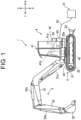
- FIG. 1 is a side view showing a schematic configuration of a hydraulic excavator 1 (electric excavator), which is an example of an electric work machine, of this embodiment.
- the hydraulic excavator 1 includes a lower traveling body 2, a work machine 3, and an upper revolving body 4.
- directions are defined as follows.
- a direction in which an operator (manipulator, driver) sitting on a driver's seat 41a of the upper revolving body 4 faces front is referred to as forward, and an opposite direction thereof is referred to as backward. Therefore, when the upper revolving body 4 is in a non-revolving state (revolving angle 0°) relative to the lower traveling body 2, a front-back direction of the upper revolving body 4 matches the direction in which the lower traveling body 2 moves forward and backward. Also, the left side as viewed from the operator seated on the driver's seat 41a is referred to as "left” and the right side as "right".
- a gravity direction perpendicular to the front-back direction and the right-left direction is defined as the up-down direction, with an upstream side of the gravity direction being “up” and a downstream side being “down.”
- the hydraulic excavator 1 is shown with the upper revolving body 4 in a state of non-revolving relative to the lower traveling body 2.
- forward is indicated by a symbol "F”, backward by “B”, rightward by “R”, leftward by “L”, upward by "U”, and downward by "D” as necessary.
- the lower traveling body 2 comprises a pair of left and right crawlers 21 and a pair of left and right traveling motors 22.
- Each of the traveling motors 22 is a hydraulic motor.
- the left and right traveling motors 22 drive the left and right crawlers 21, respectively, whereby the hydraulic excavator 1 can move forward and backward.
- a blade 23 for performing a ground leveling work and a blade cylinder 23a are provided on the lower traveling body 2.
- the blade cylinder 23a is a hydraulic cylinder that rotates the blade 23 in the up-down direction.
- the work machine 3 includes a boom 31, an arm 32, and a bucket 33.
- the boom 31, the arm 32, and the bucket 33 can be independently driven to perform excavation of earth and sand and the like.
- the boom 31 is rotated by a boom cylinder 31a.
- the boom cylinder 31a has a base end part of supported by a front portion of the upper revolving body 4 and is movable in an extendable and retractable manner.
- the arm 32 is rotated by an arm cylinder 32a.
- the arm cylinder 32a has a base end part thereof supported by a distal end part of the boom 31 and is movable in the extendable and retractable manner.
- the bucket 33 is rotated by a bucket cylinder 33a.
- the bucket cylinder 33a has a base end part thereof supported by a distal end part of the arm 32 and is movable in the extendable and retractable manner.
- the boom cylinder 31a, the arm cylinder 32a, and the bucket cylinder 33a are constituted of hydraulic cylinders.
- the upper revolving body 4 is located above the lower traveling body 2 and provided capable of revolving with respect to the lower traveling body 2 through a revolving bearing (not shown).
- a revolving bearing (not shown).
- an operation portion 41, a revolving frame 42, a revolving motor 43, an engine room 44 and the like are disposed in the upper revolving body 4.
- the upper revolving body 4 is driven by the revolving motor 43, which is a hydraulic motor, to revolve through the revolving bearing.
- the hydraulic excavator 1 includes the revolving frame 42 as the machine-body frame.
- a hydraulic pump 71 (see FIG. 2 ) is disposed on the upper revolving body 4.
- the hydraulic pump 71 is driven by an electric motor 61 (see FIG. 2 ) inside the engine room 44.
- the hydraulic pump 71 supplies hydraulic oil (pressure oil) to the hydraulic motors (the left and right traveling motors 22, the revolving motor 43, for example), and the hydraulic cylinders (the blade cylinder 23a, the boom cylinder 31a, the arm cylinder 32a, the bucket cylinder 33a, for example).
- the hydraulic motors and the hydraulic cylinders that are driven with the hydraulic oil supplied from the hydraulic pump 71 are collectively referred to as a hydraulic actuator 73 (see FIG. 2 ).
- the driver's seat 41a is disposed in the operation portion 41.
- Various levers 41b are disposed around the driver's seat 41a.
- the hydraulic actuator 73 is driven. This allows the lower traveling body 2 to travel, the blade 23 to perform the ground leveling work, the work machine 3 to perform an excavating work, and the upper revolving body 4 to revolve and the like.
- a battery unit 53 is disposed on the upper revolving body 4. That is, the hydraulic excavator 1 includes the battery unit 53.
- the battery unit 53 is constituted by a lithium-ion battery unit, for example, and stores electric power to drive the electric motor 61.
- the battery unit 53 may be constituted by a plurality of batteries as a unit or may be constituted of a single battery cell.
- a power feed port not shown, is provided in the upper revolving body 4.
- the power feed port described above and a commercial power supply 51 as an external power source are connected via a power feed cable 52. This allows the battery unit 53 to be charged.
- a lead battery 54 is further provided in the upper revolving body 4.
- the lead battery 54 outputs a low voltage (12 V, for example) direct-current voltage.
- the output from the lead battery 54 is supplied as a control voltage to, for example, a system controller 67 (see FIG. 2 ), a blower fan (not shown) and the like.
- the hydraulic excavator 1 may be so configured that a hydraulic instrument such as a hydraulic actuator 73 and an electrically-driven actuator are used in combination.
- the electrically-driven actuators include, for example, an electric traveling motor, an electric cylinder, and an electric revolving motor.
- FIG. 2 is a block diagram schematically showing configurations of an electric system and a hydraulic system of the hydraulic excavator 1.
- the hydraulic excavator 1 includes the electric motor 61, a charger 62, an inverter 63, a PDU (Power Drive Unit) 64, a junction box 65, a DC-DC converter 66, and the system controller 67.
- the system controller 67 is constituted by an electronic control unit, also called an ECU (Electronic Control Unit) and electrically controls each portion of the hydraulic excavator 1.
- ECU Electronic Control Unit
- the electric motor 61 is driven by electric power supplied from the battery unit 53 via the junction box 65 and the inverter 63.
- the electric motor 61 is constituted by a permanent magnet motor or an induction motor.
- the electric motor 61 is disposed on the revolving frame 42.
- the charger 62 converts an AC voltage supplied from the commercial power supply 51 shown in FIG. 1 via the power feed cable 52 into a DC voltage.
- the inverter 63 converts the DC voltage supplied from the battery unit 53 into an AC voltage and supplies it to the electric motor 61. As a result, the electric motor 61 is rotated.
- the supply of the AC voltage (current) from the inverter 63 to the electric motor 61 is performed on the basis of a rotation instruction output from the system controller 67.
- the PDU64 is a battery control unit that controls input/output of the battery unit 53 by controlling a battery relay inside.
- the junction box 65 is configured by including a charger relay, an inverter relay, a fuse and the like.
- the voltage output from the charger 62 is supplied to the battery unit 53 through the junction box 65 and the PDU 64.
- the voltage output from the battery unit 53 is supplied to the inverter 63 through the PDU 64 and the junction box 65.
- the DC-DC converter 66 lowers a high-voltage (300 V, for example) direct-current voltage supplied from the battery unit 53 through the junction box 65 to a low voltage (12 V, for example).
- the voltage output from the DC-DC converter 66 is, similarly to the output from the lead battery 54, supplied to the system controller 67, the blower fan, and the like.
- a plurality of the hydraulic pumps 71 are connected to a rotary shaft (output shaft) of the electric motor 61.
- the plurality of hydraulic pumps 71 include a variable-capacity pump and a fixed-capacity pump.
- FIG. 2 shows only one of the hydraulic pumps 71 as an example.
- Each hydraulic pump 71 is connected to a hydraulic-oil tank 74 that contains (stores) the hydraulic oil.
- the hydraulic pump 71 causes the hydraulic oil in the hydraulic-oil tank 74 to be supplied to the hydraulic actuator 73 through a control valve 72. As a result, the hydraulic actuator 73 is driven.
- the control valve 72 is a direction-switching valve that controls a flow direction and a flow rate of the hydraulic oil supplied to the hydraulic actuator 73.
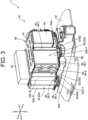
- FIG. 3 is a perspective view of an inside of the engine room 44 of the hydraulic excavator 1 when viewed from diagonally front.
- FIG. 4 is a perspective view of the inside of the engine room 44 when viewed from diagonally rear.
- the hydraulic excavator 1 includes a fixing mechanism 80.
- the fixing mechanism 80 is a mechanism that fixes the battery unit 53 to the revolving frame 42.
- the hydraulic excavator 1 includes a plurality of battery units 53.
- the fixing mechanism 80 fixes the plurality of battery units 53 to the revolving frame 42.
- the fixing mechanism 80 has an upper plate 81 as well as a lower plate 82 and a support portion 83.
- the upper plate 81 and the lower plate 82 sandwich the plurality of battery units 53 from the up-down direction.
- the upper plate 81 and lower plate 82 are coupled by a coupling member 84, described below.
- the upper plate 81 is located above the plurality of battery units 53.
- the lower plate 82 is located below the plurality of battery units 53.
- the plurality of battery units 53 and PDU 64 are connected by a connecting cable CA.
- the plurality of battery units 53 are connected in series, parallel, or a combination of series and parallel.
- FIG. 5 is a plan view showing the disposition of the battery unit 53 on the lower plate 82 in a state where the upper plate 81, the coupling member 84, and connecting cable CA are removed.
- Four units of the battery units 53 of the same size are disposed on the lower plate 82.
- two units of the battery units 53 are connected in series so as to form one pair, and the other two battery units 53 are also connected in series so as to form one pair. Each pair is then connected in parallel with each other.
- the connection method of the four battery units is not limited to the above example.
- the number of the battery units 53 is not limited to four described above, and at least one battery unit 53 needs to be provided.
- the plurality of battery units 53 are located in parallel to one direction and aligned perpendicular to one direction on the lower plate 82. In this embodiment, the plurality of battery units 53 are located in parallel to the left-right direction as the one direction described above and aligned in the front-back direction perpendicular to the one direction described above on the lower plate 82, for example.
- first battery unit 53A when the above four battery units 53 are to be specifically distinguished, they are referred to as a first battery unit 53A, a second battery unit 53B, a third battery unit 53C, and a fourth battery unit 53D in order from front to back.
- the PDU 64 described above is located in front of the first battery unit 53A.
- a lower surface of the PDU 64 is fixed to a support stay 64a (see FIG. 3 ).
- the support stay 64a is fixed on the lower plate 82.
- the first battery unit 53A and the second battery unit 53B are disposed at the same position in the left-right direction (without being shifted from each other in the left-right direction) on the lower plate 82.
- the third battery unit 53C is disposed on the lower plate 82 by being shifted to the right more than the second battery unit 53B.
- the fourth battery unit 53D is disposed further shifted to the right on the lower plate 82 than the third battery unit 53C.
- two of the four battery units 53 are located on the lower plate 82 shifted in one direction (left-right direction) from the other battery units 53 (first battery unit 53A and the second battery unit 53B). Only one of the plurality of battery units 53 may be located by being shifted in one direction. In other words, in this embodiment, at least one of the plurality of battery units 53 is located on the lower plate 82, by being shifted from the other battery units 53 in one direction.
- left end parts of the first battery unit 53A to the fourth battery unit 53D are located substantially along an edge portion 42a (see FIG. 5 ) from a left side part to a rear end part of the revolving frame 42.
- a space in the engine room 44 is effectively utilized by disposing each of the battery units 53 in the engine room 44 as close as possible to the edge portion 42a of the revolving frame 42.
- an upper surface 53S1 (see FIG. 5 ) of each battery unit 53 is preferably fixed in contact with the upper plate 81 (see FIG. 3 ), and a lower surface 53S2 (see FIG. 3 ) of each battery unit 53 is preferably fixed in contact with the lower plate 82.
- fixing of the upper surface 53S1 of each battery unit 53 to the upper plate 81 and the fixing of the lower surface 53 S2 of each battery unit 53 to the lower plate 82 are preferably performed by fastening by a bolt. In the case of bolt fastening, release of the fixation between the both is also easy.
- Each battery unit 53 may be disposed on the lower plate 82 in parallel to the front-back direction and aligned in the left-right direction. Each battery unit 53 may also be disposed on the lower plate 82 in parallel to a diagonal direction that intersects the left-right direction and aligned in a direction perpendicular to the diagonal direction. Furthermore, each battery unit 53 may be disposed by being stacked vertically on the lower plate 82.
- the support portion 83 supports the lower plate 82 on the revolving frame 42.
- Three support portions 83 are provided on the revolving frame 42, for example.
- the lower plate 82 is supported by the three support portions 83 on the revolving frame 42.
- the number of support portions 83 is not particularly limited to the three described above.
- a vibration isolating rubber or the like may be disposed between each battery unit 53 and the lower plate 82.
- the support portion 83 located below the lower plate 82 is preferably configured by including a vibration isolating member 83a.
- the vibration isolating member 83a a vibration isolating structure combining the vibration isolating rubber, a stay, a housing and the like can be used.
- the upper surfaces 53S1 and the lower surfaces 53 S2 of the battery units 53 are supported by the upper plate 81 and the lower plate 82 and thus, the integrity of the battery units 53 and the upper plate 81 and the lower plate 82 can be improved.
- the battery unit 53 can be stably supported on the revolving frame 42 through the lower plate 82 and the support portion 83, even when vibrations occur during use of the hydraulic excavator 1.
- the support portion 83 also allows the fixing mechanism 80 to be installed by avoiding (straddling) interference with a strength structural member 42b (see FIGs. 3 to 5 ) of the revolving frame 42.
- the strength structural member 42b is a reinforcing plate material of the revolving frame 42 installed across the front and back on the revolving frame 42.
- the fixing mechanism 80 has a coupling member 84.
- the coupling member 84 is a member that couples the upper plate 81 and the lower plate 82. From the viewpoint of strongly sandwiching the battery unit 53 between the upper plate 81 and the lower plate 82 from the up-down direction and from the viewpoint of reducing a load applied to a contact part (part fastened by a bolt) between the battery unit 53 and the upper plate 81 when the upper plate 81 bolted to the battery unit 53 is lifted up to move the battery unit 53 in a plant or the like, it is preferable that the upper plate 81 and the lower plate 82 are coupled by the coupling member 84 as in this embodiment.
- the fixing mechanism 80 has a first coupling member 84-1 (see FIG. 3 ), a second coupling member 84-2 (see FIG. 3 ), and a third coupling member 84-3 (see FIG. 4 ) as the coupling members 84 described above.
- the number of the coupling members 84 is not limited to the three described above.
- FIG. 6 is a cross-sectional view of the first coupling member 84-1.
- FIG. 7 is a cross-sectional view of the second coupling member 84-2.
- FIG. 8 is a cross-sectional view of the third coupling member 84-3.
- Each coupling member 84 is constituted by having an upper-plate fixing portion 84a, a lower-plate fixing portion 84b, and a coupling portion 84c.
- the upper-plate fixing portion 84a is constituted by a flat plate located below the upper plate 81 and is fastened to the upper plate 81 by bolts.
- the lower-plate fixing portion 84b is constituted by a flat plate located above the lower plate 82 and is fastened to the lower plate 82 by bolts.
- the coupling portion 84c is constituted integrally with the upper-plate fixing portion 84a and the lower-plate fixing portion 84b and couples the upper-plate fixing portion 84a and the lower-plate fixing portion 84b in the up-down direction.
- the coupling portion 84c is located horizontally (left-right direction or front-back direction) with a gap from the battery unit 53. Thus, the coupling member 84 is located away from the battery unit 53.
- the coupling member 84 preferably couples the upper plate 81 and the lower plate 82 at a position away from the battery unit 53, as shown in FIGs. 6 to 8 .
- the upper plate 81 and the lower plate 82 are preferably coupled by the coupling member 84 at least at three locations in a periphery of the plurality of battery units 53.
- the first coupling member 84-1, the second coupling member 84-2, and the third coupling member 84-3 are preferably located away from each other along an outer periphery surrounding the plurality of battery units 53, viewed from above.
- the first coupling member 84-1, the second coupling member 84-2, and the third coupling member 84-3 are preferably located on the lower plate 82 as follows.
- the first coupling member 84-1 is located in front of the first battery unit 53A, which is located at the most front among the plurality of battery units 53, the second coupling member 84-2 is located behind the first coupling member 84-1 and opposing each side surface of two or more adjacent battery units 53, and the third coupling member 84-3 is located behind the second coupling member 84-2, and with the plurality of battery units 53 (the first battery unit 53A to the third battery unit 53C, for example) interposed between the third coupling member 84-3 and the first coupling member 84-1.
- the first battery unit 53A as well as the second battery unit 53B and the third battery unit 53C are located on the lower plate 82, shifted in one direction (left-right direction).
- the second coupling member 84-2 (see FIG. 3 ) is located on the lower plate 82 and adjacent to both a right side surface 53A-R of the first battery unit 53A as well as a right side surface 53B-R of the second battery unit 53B and a front surface 53C-F of the third battery unit 53C.
- the right side surface 53A-R as well as the right side surface 53B-R and the front surface 53C-F described above have a perpendicularly intersecting positional relationship on the lower plate 82.
- the third battery unit 53C and the fourth battery unit 53D are located on the lower plate 82, shifted in the left-right direction.
- the third coupling member 84-3 (see FIG. 4 ) is located adjacent to both the rear surface 53C-B of the third battery unit 53C and the left side surface 53D-L of the fourth battery unit 53D on the lower plate 82.
- the rear surface 53C-B and the left side surface 53D-L described above have a positional relationship of perpendicularly intersecting on the lower plate 82.
- At least any one of the plurality of coupling members 84 is preferably disposed on the lower plate 82 as follows.
- at least any one of the plurality of coupling members 84 is preferably located adjacently to two perpendicularly intersecting surfaces of the two battery units 53 that are located by being shifted in one direction on the lower plate 82, viewed from above.
- the fixing mechanism 80 of this embodiment further has a positioning member 85, as shown in FIG. 3 and FIG. 4 .
- the positioning member 85 is fixed on the lower plate 82.
- the positioning member 85 is located on the lower plate 82 in contact with a bottom of any surface of the battery unit 53.
- the fixing mechanism 80 has, as the positioning members 85, a first positioning member 85-1, a second positioning member 85-2, a third positioning member 85-3, a fourth positioning member 85-4, a fifth positioning member 85-5, a sixth positioning member 85-6, a seventh positioning member 85-7, an eighth positioning member 85-8, and a ninth positioning member 85-9.
- the first positioning member 85-1 is located on the lower plate 82 in contact with the bottom of the front surface 53A-F of the first battery unit 53A.
- the second positioning member 85-2 is located on the lower plate 82 in contact with the bottom of the right side surface 53C-R of the third battery unit 53C.
- the third positioning member 85-3 is located on the lower plate 82 in contact with the bottom of the right side surface 53D-R of the fourth battery unit 53D.
- the fourth positioning member 85-4 and the fifth positioning member 85-5 are located on the lower plate 82 in contact with the bottom of the rear surface 53D-B of the fourth battery unit 53D.
- the sixth positioning member 85-6 is located on the lower plate 82 in contact with the bottom of the left side surface 53D-L of the fourth battery unit 53D.
- the seventh positioning member 85-7 is located on the lower plate 82 in contact with the bottom of the left side surface 53C-L of the third battery unit 53C.
- the eighth positioning member 85-8 is located on the lower plate 82 in contact with the bottom of the left side surface 53B-L of the second battery unit 53B.
- the ninth positioning member 85-9 is located on the lower plate 82 in contact with the bottom of the left side surface 53A-L of the first battery unit 53A.
- the fixing mechanism 80 preferably has the positioning member 85 described above.
- the junction box 65 described above is disposed on the upper plate 81 in this embodiment.
- the junction box 65 is a type of an electrical component. From the viewpoint of effective utilization of the space above the upper plate 81, it is preferable that the electrical components are disposed on the upper plate 81, that is, that the hydraulic excavator 1 includes electrical components that are disposed on the upper plate 81.
- the electrical components disposed on the upper plate 81 are not limited to the junction box 65 described above but may be other electrical components such as the PDU 64.
- the hydraulic excavator 1 described in this embodiment can also be expressed as an electric work machine as shown in the following Appendix.
- the electric work machine of Appendix (1) includes an electric motor, a machine-body frame, a battery unit that stores electric power to drive the electric motor, and a fixing mechanism that fixes the battery unit to the machine-body frame, the fixing mechanism having an upper plate and a lower plate that sandwich the battery unit from the up-down direction and a support portion that supports the lower plate on the machine-body frame.
- the support portion includes a vibration isolating member in the electric work machine described in Appendix (1).
- an upper surface of the battery unit is fixed in contact with the upper plate and a lower surface of the battery unit is fixed in contact with the lower plate.
- the fixing mechanism has a coupling member, and the coupling member couples the upper plate and the lower plate.
- the coupling member couples the upper plate and the lower plate at a position away from the battery unit.
- the upper plate and the lower plate sandwich a plurality of the battery units from the up-down direction
- the plurality of battery units are located in parallel to one direction on the lower plate and aligned in a direction perpendicular to the one direction
- at least any one of the plurality of battery units is located on the lower plate by being shifted from the other battery units in the one direction
- the fixing mechanism has a plurality of the coupling members, at least any one of the plurality of coupling members is located adjacently to two perpendicularly intersecting surfaces of the two battery units that are located by being shifted in the one direction on the lower plate, viewed from above.
- the fixing mechanism has a first coupling member, a second coupling member, and a third coupling member as the coupling members, and the first coupling member, the second coupling member, and the third coupling member are located away from each other along an outer periphery surrounding a plurality of the battery units, viewed from above.
- a plurality of the battery units are located on the lower plate in parallel to a left-right direction as the one direction and aligned in a front-back direction perpendicular to the one direction, the first coupling member is located in front of a battery unit located at the most front among a plurality of the battery units, the second coupling member is located behind the first coupling member and opposing each side surface of two or more adjacent battery units, and the third coupling member is located behind the second coupling member, and with the plurality of battery units interposed between the first coupling member and the third coupling member.
- the fixing mechanism further has a positioning member fixed on the lower plate, and the positioning member is located on the lower plate in contact with a bottom of any surface of the battery unit.
- the electric work machine of Appendix (10) further includes electrical components disposed on the upper plate of the electric work machine described in any one of Appendices (1) to (9).
- each battery unit 53 is all the same, but some of the battery units 53 with a different size may be used.
- the hydraulic excavator 1 which is a construction machine, as the example of the electric work machine, but the electric work machine is not limited to the hydraulic excavator 1 and may be any other construction machines such as a wheel loader. Also, the electric work machine may be an agricultural machine such as a combine harvester, a tractor or the like.
- the present invention is applicable to work machines such as a construction machine and an agricultural machine, for example.
Landscapes
- Engineering & Computer Science (AREA)
- Mining & Mineral Resources (AREA)
- Civil Engineering (AREA)
- General Engineering & Computer Science (AREA)
- Structural Engineering (AREA)
- Mechanical Engineering (AREA)
- Power Engineering (AREA)
- Chemical & Material Sciences (AREA)
- Transportation (AREA)
- Chemical Kinetics & Catalysis (AREA)
- Electrochemistry (AREA)
- General Chemical & Material Sciences (AREA)
- Life Sciences & Earth Sciences (AREA)
- Sustainable Development (AREA)
- Sustainable Energy (AREA)
- Combustion & Propulsion (AREA)
- Aviation & Aerospace Engineering (AREA)
- Battery Mounting, Suspending (AREA)
- Arrangement Or Mounting Of Propulsion Units For Vehicles (AREA)
Abstract
Description
- The present invention relates to an electric work machine.
- Conventionally, various types of revolving work machines including electric motors have been proposed. The electric motor is driven by electric power supplied from a battery unit. The battery unit is supported on a revolving platform of the revolving work machine. For example, the revolving work machine of Patent Document 1 has a standing frame that supports the battery unit. The standing frame described above has a first standing portion and a second standing portion. The first standing portion stands on an upper part of the revolving platform and supports one side surface (a left side surface, for example) of the battery unit. The second standing portion stands on the upper part of the revolving platform and supports another side surface (a right side surface, for example) of the battery unit.
- Patent Document 1:
Japanese Unexamined Patent Application Publication No. 2021-080704 - Considering that the revolving work machine is used on an uneven land and vibrates, the battery unit is preferably supported on the revolving platform (machine-body frame) integrally with the standing frame. In the configuration of supporting the battery unit on the revolving platform from a left-right direction as in Patent Document 1, since an upper surface of the battery unit is not supported in any way, integrity of the battery unit and the standing frame is insufficient, and there is room for improvement in terms of stable support of the battery unit against vibration.
- The present invention was made in order to solve the above-mentioned problems, and an object thereof is to provide an electric work machine capable of stably supporting a battery unit on a machine-body frame even if vibration occurs.
- An electric work machine according to one aspect of the present invention includes an electric motor, a machine-body frame, a battery unit that stores electric power to drive the electric motor, and a fixing mechanism that fixes the battery unit to the machined-body frame, in which the fixing mechanism has an upper plate and a lower plate that sandwich the battery unit from an up-down direction and a support portion that supports the lower plate on the machine-body frame.
- The battery unit can be stably supported on the machine-body frame even when vibration occurs.
-
-
FIG. 1 is a side view showing a schematic configuration of a hydraulic excavator, which is an example of an electric work machine according to an embodiment of the present invention. -
FIG. 2 is a block diagram schematically showing configurations of an electric system and a hydraulic system of the hydraulic excavator. -
FIG. 3 is a perspective view of an inside of an engine room of the hydraulic excavator when viewed from diagonally front. -
FIG. 4 is a perspective view of the inside of the engine room when viewed from diagonally rear. -
FIG. 5 is a plan view showing disposition of the battery unit on the lower plate. -
FIG. 6 is a sectional view of a first coupling member. -
FIG. 7 is a sectional view of a second coupling member. -
FIG. 8 is a sectional view of a third coupling member. - An embodiment of the present invention will be explained on the basis of drawings as follows.
-
FIG. 1 is a side view showing a schematic configuration of a hydraulic excavator 1 (electric excavator), which is an example of an electric work machine, of this embodiment. The hydraulic excavator 1 includes alower traveling body 2, awork machine 3, and an upper revolving body 4. - Here, directions are defined as follows. A direction in which an operator (manipulator, driver) sitting on a driver's
seat 41a of the upper revolving body 4 faces front is referred to as forward, and an opposite direction thereof is referred to as backward. Therefore, when the upper revolving body 4 is in a non-revolving state (revolving angle 0°) relative to the lower travelingbody 2, a front-back direction of the upper revolving body 4 matches the direction in which the lower travelingbody 2 moves forward and backward. Also, the left side as viewed from the operator seated on the driver'sseat 41a is referred to as "left" and the right side as "right". Moreover, a gravity direction perpendicular to the front-back direction and the right-left direction is defined as the up-down direction, with an upstream side of the gravity direction being "up" and a downstream side being "down." In the drawings, the hydraulic excavator 1 is shown with the upper revolving body 4 in a state of non-revolving relative to the lowertraveling body 2. Also, in the drawings, forward is indicated by a symbol "F", backward by "B", rightward by "R", leftward by "L", upward by "U", and downward by "D" as necessary. - The lower
traveling body 2 comprises a pair of left andright crawlers 21 and a pair of left andright traveling motors 22. Each of thetraveling motors 22 is a hydraulic motor. The left and right travelingmotors 22 drive the left andright crawlers 21, respectively, whereby the hydraulic excavator 1 can move forward and backward. On the lower travelingbody 2, ablade 23 for performing a ground leveling work and ablade cylinder 23a are provided. Theblade cylinder 23a is a hydraulic cylinder that rotates theblade 23 in the up-down direction. - The
work machine 3 includes aboom 31, anarm 32, and abucket 33. Theboom 31, thearm 32, and thebucket 33 can be independently driven to perform excavation of earth and sand and the like. - The
boom 31 is rotated by aboom cylinder 31a. Theboom cylinder 31a has a base end part of supported by a front portion of the upper revolving body 4 and is movable in an extendable and retractable manner. Thearm 32 is rotated by anarm cylinder 32a. Thearm cylinder 32a has a base end part thereof supported by a distal end part of theboom 31 and is movable in the extendable and retractable manner. Thebucket 33 is rotated by abucket cylinder 33a. Thebucket cylinder 33a has a base end part thereof supported by a distal end part of thearm 32 and is movable in the extendable and retractable manner. Theboom cylinder 31a, thearm cylinder 32a, and thebucket cylinder 33a are constituted of hydraulic cylinders. - The upper revolving body 4 is located above the lower traveling
body 2 and provided capable of revolving with respect to the lower travelingbody 2 through a revolving bearing (not shown). In the upper revolving body 4, anoperation portion 41, a revolvingframe 42, a revolvingmotor 43, anengine room 44 and the like are disposed. The upper revolving body 4 is driven by the revolvingmotor 43, which is a hydraulic motor, to revolve through the revolving bearing. The hydraulic excavator 1 includes the revolvingframe 42 as the machine-body frame. - A hydraulic pump 71 (see
FIG. 2 ) is disposed on the upper revolving body 4. Thehydraulic pump 71 is driven by an electric motor 61 (seeFIG. 2 ) inside theengine room 44. Thehydraulic pump 71 supplies hydraulic oil (pressure oil) to the hydraulic motors (the left andright traveling motors 22, the revolvingmotor 43, for example), and the hydraulic cylinders (theblade cylinder 23a, theboom cylinder 31a, thearm cylinder 32a, thebucket cylinder 33a, for example). The hydraulic motors and the hydraulic cylinders that are driven with the hydraulic oil supplied from thehydraulic pump 71 are collectively referred to as a hydraulic actuator 73 (seeFIG. 2 ). - The driver's
seat 41a is disposed in theoperation portion 41.Various levers 41b are disposed around the driver'sseat 41a. When the operator sitting on the driver'sseat 41a operates thelever 41b, thehydraulic actuator 73 is driven. This allows thelower traveling body 2 to travel, theblade 23 to perform the ground leveling work, thework machine 3 to perform an excavating work, and the upper revolving body 4 to revolve and the like. - A
battery unit 53 is disposed on the upper revolving body 4. That is, the hydraulic excavator 1 includes thebattery unit 53. Thebattery unit 53 is constituted by a lithium-ion battery unit, for example, and stores electric power to drive theelectric motor 61. Thebattery unit 53 may be constituted by a plurality of batteries as a unit or may be constituted of a single battery cell. Moreover, in the upper revolving body 4, a power feed port, not shown, is provided. The power feed port described above and acommercial power supply 51 as an external power source are connected via apower feed cable 52. This allows thebattery unit 53 to be charged. - In the upper revolving body 4, a
lead battery 54 is further provided. Thelead battery 54 outputs a low voltage (12 V, for example) direct-current voltage. The output from thelead battery 54 is supplied as a control voltage to, for example, a system controller 67 (seeFIG. 2 ), a blower fan (not shown) and the like. - The hydraulic excavator 1 may be so configured that a hydraulic instrument such as a
hydraulic actuator 73 and an electrically-driven actuator are used in combination. The electrically-driven actuators include, for example, an electric traveling motor, an electric cylinder, and an electric revolving motor. -
FIG. 2 is a block diagram schematically showing configurations of an electric system and a hydraulic system of the hydraulic excavator 1. The hydraulic excavator 1 includes theelectric motor 61, acharger 62, aninverter 63, a PDU (Power Drive Unit) 64, ajunction box 65, a DC-DC converter 66, and thesystem controller 67. Thesystem controller 67 is constituted by an electronic control unit, also called an ECU (Electronic Control Unit) and electrically controls each portion of the hydraulic excavator 1. - The
electric motor 61 is driven by electric power supplied from thebattery unit 53 via thejunction box 65 and theinverter 63. Theelectric motor 61 is constituted by a permanent magnet motor or an induction motor. Theelectric motor 61 is disposed on the revolvingframe 42. - The
charger 62 converts an AC voltage supplied from thecommercial power supply 51 shown inFIG. 1 via thepower feed cable 52 into a DC voltage. Theinverter 63 converts the DC voltage supplied from thebattery unit 53 into an AC voltage and supplies it to theelectric motor 61. As a result, theelectric motor 61 is rotated. The supply of the AC voltage (current) from theinverter 63 to theelectric motor 61 is performed on the basis of a rotation instruction output from thesystem controller 67. - The PDU64 is a battery control unit that controls input/output of the
battery unit 53 by controlling a battery relay inside. Thejunction box 65 is configured by including a charger relay, an inverter relay, a fuse and the like. The voltage output from thecharger 62 is supplied to thebattery unit 53 through thejunction box 65 and thePDU 64.
Moreover, the voltage output from thebattery unit 53 is supplied to theinverter 63 through thePDU 64 and thejunction box 65. - The DC-
DC converter 66 lowers a high-voltage (300 V, for example) direct-current voltage supplied from thebattery unit 53 through thejunction box 65 to a low voltage (12 V, for example). The voltage output from the DC-DC converter 66 is, similarly to the output from thelead battery 54, supplied to thesystem controller 67, the blower fan, and the like. - A plurality of the
hydraulic pumps 71 are connected to a rotary shaft (output shaft) of theelectric motor 61. The plurality ofhydraulic pumps 71 include a variable-capacity pump and a fixed-capacity pump.FIG. 2 shows only one of thehydraulic pumps 71 as an example. Eachhydraulic pump 71 is connected to a hydraulic-oil tank 74 that contains (stores) the hydraulic oil. Thehydraulic pump 71 causes the hydraulic oil in the hydraulic-oil tank 74 to be supplied to thehydraulic actuator 73 through acontrol valve 72. As a result, thehydraulic actuator 73 is driven. Thecontrol valve 72 is a direction-switching valve that controls a flow direction and a flow rate of the hydraulic oil supplied to thehydraulic actuator 73. - Subsequently, a fixing mechanism of the
battery unit 53 described above will be explained.FIG. 3 is a perspective view of an inside of theengine room 44 of the hydraulic excavator 1 when viewed from diagonally front.FIG. 4 is a perspective view of the inside of theengine room 44 when viewed from diagonally rear. - As shown in these figures, the hydraulic excavator 1 includes a
fixing mechanism 80. The fixingmechanism 80 is a mechanism that fixes thebattery unit 53 to the revolvingframe 42. In this embodiment, the hydraulic excavator 1 includes a plurality ofbattery units 53. Thus, the fixingmechanism 80 fixes the plurality ofbattery units 53 to the revolvingframe 42. - The fixing
mechanism 80 has anupper plate 81 as well as alower plate 82 and a support portion 83. Theupper plate 81 and thelower plate 82 sandwich the plurality ofbattery units 53 from the up-down direction. Theupper plate 81 andlower plate 82 are coupled by acoupling member 84, described below. - The
upper plate 81 is located above the plurality ofbattery units 53. Thelower plate 82 is located below the plurality ofbattery units 53. The plurality ofbattery units 53 andPDU 64 are connected by a connecting cable CA. In particular, the plurality ofbattery units 53 are connected in series, parallel, or a combination of series and parallel. -
FIG. 5 is a plan view showing the disposition of thebattery unit 53 on thelower plate 82 in a state where theupper plate 81, thecoupling member 84, and connecting cable CA are removed. Four units of thebattery units 53 of the same size are disposed on thelower plate 82. For example, two units of thebattery units 53 are connected in series so as to form one pair, and the other twobattery units 53 are also connected in series so as to form one pair. Each pair is then connected in parallel with each other. The connection method of the four battery units is not limited to the above example. The number of thebattery units 53 is not limited to four described above, and at least onebattery unit 53 needs to be provided. - In this embodiment, the plurality of
battery units 53 are located in parallel to one direction and aligned perpendicular to one direction on thelower plate 82. In this embodiment, the plurality ofbattery units 53 are located in parallel to the left-right direction as the one direction described above and aligned in the front-back direction perpendicular to the one direction described above on thelower plate 82, for example. - Here, when the above four
battery units 53 are to be specifically distinguished, they are referred to as afirst battery unit 53A, asecond battery unit 53B, athird battery unit 53C, and afourth battery unit 53D in order from front to back. ThePDU 64 described above is located in front of thefirst battery unit 53A. A lower surface of thePDU 64 is fixed to asupport stay 64a (seeFIG. 3 ). Thesupport stay 64a is fixed on thelower plate 82. - As shown in
FIG. 5 , thefirst battery unit 53A and thesecond battery unit 53B are disposed at the same position in the left-right direction (without being shifted from each other in the left-right direction) on thelower plate 82. Thethird battery unit 53C is disposed on thelower plate 82 by being shifted to the right more than thesecond battery unit 53B. Thefourth battery unit 53D is disposed further shifted to the right on thelower plate 82 than thethird battery unit 53C. - Therefore, it can be considered that two of the four battery units 53 (the
third battery unit 53C and thefourth battery unit 53D) are located on thelower plate 82 shifted in one direction (left-right direction) from the other battery units 53 (first battery unit 53A and thesecond battery unit 53B). Only one of the plurality ofbattery units 53 may be located by being shifted in one direction. In other words, in this embodiment, at least one of the plurality ofbattery units 53 is located on thelower plate 82, by being shifted from theother battery units 53 in one direction. - In the disposition of the plurality of
battery units 53 as above, left end parts of thefirst battery unit 53A to thefourth battery unit 53D are located substantially along anedge portion 42a (seeFIG. 5 ) from a left side part to a rear end part of the revolvingframe 42. As described above, a space in theengine room 44 is effectively utilized by disposing each of thebattery units 53 in theengine room 44 as close as possible to theedge portion 42a of the revolvingframe 42. - From the viewpoint of improving integrity of each
battery unit 53 with theupper plate 81 and thelower plate 82, an upper surface 53S1 (seeFIG. 5 ) of eachbattery unit 53 is preferably fixed in contact with the upper plate 81 (seeFIG. 3 ), and a lower surface 53S2 (seeFIG. 3 ) of eachbattery unit 53 is preferably fixed in contact with thelower plate 82. - From the viewpoint of facilitating replacement of each
battery unit 53 due to life span, an operation failure and the like, fixing of the upper surface 53S1 of eachbattery unit 53 to theupper plate 81 and the fixing of thelower surface 53 S2 of eachbattery unit 53 to thelower plate 82 are preferably performed by fastening by a bolt. In the case of bolt fastening, release of the fixation between the both is also easy. - Each
battery unit 53 may be disposed on thelower plate 82 in parallel to the front-back direction and aligned in the left-right direction. Eachbattery unit 53 may also be disposed on thelower plate 82 in parallel to a diagonal direction that intersects the left-right direction and aligned in a direction perpendicular to the diagonal direction. Furthermore, eachbattery unit 53 may be disposed by being stacked vertically on thelower plate 82. - The support portion 83 supports the
lower plate 82 on the revolvingframe 42. Three support portions 83 are provided on the revolvingframe 42, for example. In other words, thelower plate 82 is supported by the three support portions 83 on the revolvingframe 42. The number of support portions 83 is not particularly limited to the three described above. - As an anti-vibration measure for each
battery unit 53, a vibration isolating rubber or the like may be disposed between eachbattery unit 53 and thelower plate 82. However, from the viewpoint of giving priority to improvement of integrity of eachbattery unit 53 and thelower plate 82 and fixing the lower surface 53S2 of eachbattery unit 53 in direct contact with thelower plate 82, the support portion 83 located below thelower plate 82 is preferably configured by including a vibration isolating member 83a. As the vibration isolating member 83a, a vibration isolating structure combining the vibration isolating rubber, a stay, a housing and the like can be used. - In the configuration in which (a plurality of) the
battery units 53 are sandwiched between theupper plate 81 and thelower plate 82 from the up-down direction as in this embodiment, the upper surfaces 53S1 and thelower surfaces 53 S2 of thebattery units 53 are supported by theupper plate 81 and thelower plate 82 and thus, the integrity of thebattery units 53 and theupper plate 81 and thelower plate 82 can be improved. As a result, thebattery unit 53 can be stably supported on the revolvingframe 42 through thelower plate 82 and the support portion 83, even when vibrations occur during use of the hydraulic excavator 1. The support portion 83 also allows thefixing mechanism 80 to be installed by avoiding (straddling) interference with a strengthstructural member 42b (seeFIGs. 3 to 5 ) of the revolvingframe 42. The strengthstructural member 42b is a reinforcing plate material of the revolvingframe 42 installed across the front and back on the revolvingframe 42. - As shown in
FIGs. 3 and4 , the fixingmechanism 80 has acoupling member 84. Thecoupling member 84 is a member that couples theupper plate 81 and thelower plate 82. From the viewpoint of strongly sandwiching thebattery unit 53 between theupper plate 81 and thelower plate 82 from the up-down direction and from the viewpoint of reducing a load applied to a contact part (part fastened by a bolt) between thebattery unit 53 and theupper plate 81 when theupper plate 81 bolted to thebattery unit 53 is lifted up to move thebattery unit 53 in a plant or the like, it is preferable that theupper plate 81 and thelower plate 82 are coupled by thecoupling member 84 as in this embodiment. - In this embodiment, the fixing
mechanism 80 has a first coupling member 84-1 (seeFIG. 3 ), a second coupling member 84-2 (seeFIG. 3 ), and a third coupling member 84-3 (seeFIG. 4 ) as thecoupling members 84 described above. The number of thecoupling members 84 is not limited to the three described above. -
FIG. 6 is a cross-sectional view of the first coupling member 84-1.FIG. 7 is a cross-sectional view of the second coupling member 84-2.FIG. 8 is a cross-sectional view of the third coupling member 84-3. Eachcoupling member 84 is constituted by having an upper-plate fixing portion 84a, a lower-plate fixing portion 84b, and acoupling portion 84c. - The upper-
plate fixing portion 84a is constituted by a flat plate located below theupper plate 81 and is fastened to theupper plate 81 by bolts. The lower-plate fixing portion 84b is constituted by a flat plate located above thelower plate 82 and is fastened to thelower plate 82 by bolts. Thecoupling portion 84c is constituted integrally with the upper-plate fixing portion 84a and the lower-plate fixing portion 84b and couples the upper-plate fixing portion 84a and the lower-plate fixing portion 84b in the up-down direction. - The
coupling portion 84c is located horizontally (left-right direction or front-back direction) with a gap from thebattery unit 53. Thus, thecoupling member 84 is located away from thebattery unit 53. - From the viewpoint of increasing heat radiation efficiency of each
battery unit 53, thecoupling member 84 preferably couples theupper plate 81 and thelower plate 82 at a position away from thebattery unit 53, as shown inFIGs. 6 to 8 . - Moreover, from the viewpoint of coupling the
upper plate 81 and thelower plate 82, which sandwich the plurality ofbattery units 53 from the up-down direction, in a well-balanced manner, and from the viewpoint of stably suspending an integral unit (fixed unit) with the plurality ofbattery units 53 sandwiched between theupper plate 81 and thelower plate 82 in a plant, for example, theupper plate 81 and thelower plate 82 are preferably coupled by thecoupling member 84 at least at three locations in a periphery of the plurality ofbattery units 53. In order to realize this configuration, as shown inFIGs. 3 and4 , the first coupling member 84-1, the second coupling member 84-2, and the third coupling member 84-3 are preferably located away from each other along an outer periphery surrounding the plurality ofbattery units 53, viewed from above. - Moreover, from the viewpoint of coupling the
upper plate 81 and thelower plate 82 by the threecoupling members 84 in a well-balanced manner and of preventing the plurality ofbattery units 53 from collapsing in the front-back direction, the first coupling member 84-1, the second coupling member 84-2, and the third coupling member 84-3 are preferably located on thelower plate 82 as follows. - In other words, as shown in
FIGs. 3 and4 , it is preferable that the first coupling member 84-1 is located in front of thefirst battery unit 53A, which is located at the most front among the plurality ofbattery units 53, the second coupling member 84-2 is located behind the first coupling member 84-1 and opposing each side surface of two or moreadjacent battery units 53, and the third coupling member 84-3 is located behind the second coupling member 84-2, and with the plurality of battery units 53 (thefirst battery unit 53A to thethird battery unit 53C, for example) interposed between the third coupling member 84-3 and the first coupling member 84-1. - In this embodiment, as shown in
FIG. 5 , thefirst battery unit 53A as well as thesecond battery unit 53B and thethird battery unit 53C are located on thelower plate 82, shifted in one direction (left-right direction). In this configuration, the second coupling member 84-2 (seeFIG. 3 ) is located on thelower plate 82 and adjacent to both aright side surface 53A-R of thefirst battery unit 53A as well as aright side surface 53B-R of thesecond battery unit 53B and afront surface 53C-F of thethird battery unit 53C. Theright side surface 53A-R as well as theright side surface 53B-R and thefront surface 53C-F described above have a perpendicularly intersecting positional relationship on thelower plate 82. - Moreover, in this embodiment, the
third battery unit 53C and thefourth battery unit 53D are located on thelower plate 82, shifted in the left-right direction. In this configuration, the third coupling member 84-3 (seeFIG. 4 ) is located adjacent to both therear surface 53C-B of thethird battery unit 53C and theleft side surface 53D-L of thefourth battery unit 53D on thelower plate 82. Therear surface 53C-B and theleft side surface 53D-L described above have a positional relationship of perpendicularly intersecting on thelower plate 82. - In the configuration in which the adjacent two
battery units 53 are located by being shifted from each other in one direction (left-right direction, for example) on thelower plate 82 as in this embodiment, when thefixing mechanism 80 has a plurality of thecoupling members 84, from the viewpoint of effectively utilizing a free area on the lower plate 82 (the remaining area excluding the area where thebattery unit 53 is disposed), at least any one of the plurality ofcoupling members 84 is preferably disposed on thelower plate 82 as follows. In other words, at least any one of the plurality ofcoupling members 84 is preferably located adjacently to two perpendicularly intersecting surfaces of the twobattery units 53 that are located by being shifted in one direction on thelower plate 82, viewed from above. - The fixing
mechanism 80 of this embodiment further has a positioningmember 85, as shown inFIG. 3 andFIG. 4 . The positioningmember 85 is fixed on thelower plate 82. Moreover, the positioningmember 85 is located on thelower plate 82 in contact with a bottom of any surface of thebattery unit 53. - For example, the fixing
mechanism 80 has, as thepositioning members 85, a first positioning member 85-1, a second positioning member 85-2, a third positioning member 85-3, a fourth positioning member 85-4, a fifth positioning member 85-5, a sixth positioning member 85-6, a seventh positioning member 85-7, an eighth positioning member 85-8, and a ninth positioning member 85-9. - As shown in
FIG. 3 , the first positioning member 85-1 is located on thelower plate 82 in contact with the bottom of thefront surface 53A-F of thefirst battery unit 53A. The second positioning member 85-2 is located on thelower plate 82 in contact with the bottom of theright side surface 53C-R of thethird battery unit 53C. The third positioning member 85-3 is located on thelower plate 82 in contact with the bottom of theright side surface 53D-R of thefourth battery unit 53D. - As shown in
FIG. 4 , the fourth positioning member 85-4 and the fifth positioning member 85-5 are located on thelower plate 82 in contact with the bottom of therear surface 53D-B of thefourth battery unit 53D. The sixth positioning member 85-6 is located on thelower plate 82 in contact with the bottom of theleft side surface 53D-L of thefourth battery unit 53D. The seventh positioning member 85-7 is located on thelower plate 82 in contact with the bottom of theleft side surface 53C-L of thethird battery unit 53C. The eighth positioning member 85-8 is located on thelower plate 82 in contact with the bottom of theleft side surface 53B-L of thesecond battery unit 53B. The ninth positioning member 85-9 is located on thelower plate 82 in contact with the bottom of theleft side surface 53A-L of thefirst battery unit 53A. - From the viewpoint of reducing a risk of a positional shift of the
battery unit 53 with respect to thelower plate 82 and of fixing thebattery unit 53 at an appropriate position (by bolts, for example) on thelower plate 82, the fixingmechanism 80 preferably has the positioningmember 85 described above. - As shown in
FIG. 3 andFIG. 4 , thejunction box 65 described above is disposed on theupper plate 81 in this embodiment. Thejunction box 65 is a type of an electrical component. From the viewpoint of effective utilization of the space above theupper plate 81, it is preferable that the electrical components are disposed on theupper plate 81, that is, that the hydraulic excavator 1 includes electrical components that are disposed on theupper plate 81. The electrical components disposed on theupper plate 81 are not limited to thejunction box 65 described above but may be other electrical components such as thePDU 64. - The hydraulic excavator 1 described in this embodiment can also be expressed as an electric work machine as shown in the following Appendix.
- The electric work machine of Appendix (1) includes an electric motor, a machine-body frame, a battery unit that stores electric power to drive the electric motor, and a fixing mechanism that fixes the battery unit to the machine-body frame, the fixing mechanism having an upper plate and a lower plate that sandwich the battery unit from the up-down direction and a support portion that supports the lower plate on the machine-body frame.
- In the electric work machine of Appendix (2), the support portion includes a vibration isolating member in the electric work machine described in Appendix (1).
- In the electric work machine of Appendix (3), in the electric work machine described in Appendix (1) or (2), an upper surface of the battery unit is fixed in contact with the upper plate and a lower surface of the battery unit is fixed in contact with the lower plate.
- In the electric work machine of Appendix (4), in the electric work machine described in any one of Appendices (1) to (3), the fixing mechanism has a coupling member, and the coupling member couples the upper plate and the lower plate.
- In the electric work machine of Appendix (5), in the electric work machine described in Appendix (4), the coupling member couples the upper plate and the lower plate at a position away from the battery unit.
- In the electric work machine of Appendix (6), in the electric work machine described in Appendix (4) or (5), the upper plate and the lower plate sandwich a plurality of the battery units from the up-down direction, the plurality of battery units are located in parallel to one direction on the lower plate and aligned in a direction perpendicular to the one direction, at least any one of the plurality of battery units is located on the lower plate by being shifted from the other battery units in the one direction, and the fixing mechanism has a plurality of the coupling members, at least any one of the plurality of coupling members is located adjacently to two perpendicularly intersecting surfaces of the two battery units that are located by being shifted in the one direction on the lower plate, viewed from above.
- In the electric work machine of Appendix (7), in the electric work machine described in Appendix (6), the fixing mechanism has a first coupling member, a second coupling member, and a third coupling member as the coupling members, and the first coupling member, the second coupling member, and the third coupling member are located away from each other along an outer periphery surrounding a plurality of the battery units, viewed from above.
- In the electric work machine of Appendix (8), in the electric work machine described in Appendix (7), a plurality of the battery units are located on the lower plate in parallel to a left-right direction as the one direction and aligned in a front-back direction perpendicular to the one direction, the first coupling member is located in front of a battery unit located at the most front among a plurality of the battery units, the second coupling member is located behind the first coupling member and opposing each side surface of two or more adjacent battery units, and the third coupling member is located behind the second coupling member, and with the plurality of battery units interposed between the first coupling member and the third coupling member.
- In the electric work machine of Appendix (9), in the electric work machine described in any one of Appendices (1) to (8), the fixing mechanism further has a positioning member fixed on the lower plate, and the positioning member is located on the lower plate in contact with a bottom of any surface of the battery unit.
- The electric work machine of Appendix (10) further includes electrical components disposed on the upper plate of the electric work machine described in any one of Appendices (1) to (9).
- In this embodiment, a size (a length in one direction, for example) of each
battery unit 53 is all the same, but some of thebattery units 53 with a different size may be used. - The description has been made with the hydraulic excavator 1, which is a construction machine, as the example of the electric work machine, but the electric work machine is not limited to the hydraulic excavator 1 and may be any other construction machines such as a wheel loader. Also, the electric work machine may be an agricultural machine such as a combine harvester, a tractor or the like.
- The embodiment of the present invention has been described above, but the scope of the present invention is not limited thereto, but can be worked with extension or modification within a range without departing from the gist of the invention.
- The present invention is applicable to work machines such as a construction machine and an agricultural machine, for example.
-
- 1 Hydraulic excavator (electric work machine)
- 42 Revolving frame (machine-body frame)
- 53 Battery unit
- 53A First battery unit (battery unit)
- 53B Second battery unit (battery unit)
- 53C Third battery unit (battery unit)
- 53D Fourth battery unit (battery unit)
- 53S1 Upper surface
- 53S2 Lower surface
- 61 Electric motor
- 65 Junction box (electrical components)
- 80 Fixing Mechanism
- 81 Upper plate
- 82 Lower plate
- 83 Support portion
- 83a Vibration isolating member
- 84 Coupling member
- 84-1 First coupling member
- 84-2 Second coupling member
- 84-3 Third coupling member
- 85 Positioning member
- 85-1 First positioning member
- 85-2 Second positioning member
- 85-3 Third positioning member
- 85-4 Fourth positioning member
- 85-5 Fifth positioning member
- 85-6 Sixth positioning member
- 85-7 Seventh positioning member
- 85-8 Eighth positioning member
- 85-9 Ninth positioning member
Claims (10)
- An electric work machine, comprising:an electric motor;a machine-body frame;a battery unit that stores electric power to drive the electric motor; anda fixing mechanism that fixes the battery unit to the machine-body frame, whereinthe fixing mechanism has:an upper plate and a lower plate that sandwich the battery unit from an up-down direction; anda support portion that supports the lower plate on the machine-body frame.
- The electric work machine according to claim 1, wherein
the support portion includes a vibration isolating member. - The electric work machine according to claim 1, whereinan upper surface of the battery unit is fixed in contact with the upper plate; anda lower surface of the battery unit is fixed in contact with the lower plate.
- The electric work machine according to claim 1, whereinthe fixing mechanism has a coupling member; andthe coupling member couples the upper plate and the lower plate.
- The electric work machine according to claim 4, wherein
the coupling member couples the upper plate and the lower plate at a position away from the battery unit. - The electric work machine according to claim 4, whereinthe upper plate and the lower plate sandwich a plurality of the battery units from the up-down direction;the plurality of battery units are located in parallel to one direction on the lower plate and aligned in a direction perpendicular to the one direction;at least any one of the plurality of battery units is located on the lower plate by being shifted from the other battery units in the one direction;the fixing mechanism has a plurality of the coupling members; and
at least any one of the plurality of coupling members is located adjacently to two perpendicularly intersecting surfaces of the two battery units that are located by being shifted in the one direction on the lower plate, viewed from above. - The electric work machine according to claim 6, whereinthe fixing mechanism has a first coupling member, a second coupling member, and a third coupling member as the coupling members; andthe first coupling member, the second coupling member, and the third coupling member are located away from each other along an outer periphery surrounding a plurality of the battery units, viewed from above.
- The electric work machine according to claim 7, whereina plurality of the battery units are located on the lower plate in parallel to a left-right direction as the one direction and aligned in a front-back direction perpendicular to the one direction;the first coupling member is located in front of a battery unit located at the most front among a plurality of the battery units;the second coupling member is located behind the first coupling member and opposing each side surface of two or more adjacent battery units; and
the third coupling member is located behind the second coupling member, and with the plurality of battery units interposed between the first coupling member and the third coupling member. - The electric work machine according to claim 1, whereinthe fixing mechanism further has a positioning member fixed on the lower plate; andthe positioning member is located on the lower plate in contact with a bottom of any surface of the battery unit.
- The electric work machine according to any one of claims 1 to 9, further comprising:
electrical components disposed on the upper plate.
Applications Claiming Priority (1)
| Application Number | Priority Date | Filing Date | Title |
|---|---|---|---|
| JP2022070961A JP2023160537A (en) | 2022-04-22 | 2022-04-22 | electric work machine |
Publications (1)
| Publication Number | Publication Date |
|---|---|
| EP4265854A1 true EP4265854A1 (en) | 2023-10-25 |
Family
ID=86282674
Family Applications (1)
| Application Number | Title | Priority Date | Filing Date |
|---|---|---|---|
| EP23166358.4A Pending EP4265854A1 (en) | 2022-04-22 | 2023-04-03 | Electric work machine |
Country Status (5)
| Country | Link |
|---|---|
| US (1) | US12611921B2 (en) |
| EP (1) | EP4265854A1 (en) |
| JP (1) | JP2023160537A (en) |
| KR (1) | KR20230150724A (en) |
| CN (1) | CN116937062A (en) |
Citations (5)
| Publication number | Priority date | Publication date | Assignee | Title |
|---|---|---|---|---|
| US20130313030A1 (en) * | 2011-03-24 | 2013-11-28 | Yukinori Matsumura | Electric work vehicle and battery holding structure thereof |
| US20140234062A1 (en) * | 2011-10-26 | 2014-08-21 | Sumitomo Heavy Industries, Ltd. | Shovel |
| EP3361550A2 (en) * | 2017-02-08 | 2018-08-15 | Denso Corporation | Power source apparatus and work machine having the same |
| JP2018162610A (en) * | 2017-03-27 | 2018-10-18 | 株式会社竹内製作所 | Battery attachment structure |
| JP2021080704A (en) | 2019-11-18 | 2021-05-27 | 株式会社クボタ | Revolving work machine |
Family Cites Families (19)
| Publication number | Priority date | Publication date | Assignee | Title |
|---|---|---|---|---|
| JP3030242B2 (en) * | 1995-11-28 | 2000-04-10 | 新キャタピラー三菱株式会社 | Construction machinery |
| JP3664363B2 (en) * | 1998-11-09 | 2005-06-22 | 松下電器産業株式会社 | Battery storage module device and battery storage device |
| JP4335770B2 (en) * | 2004-09-16 | 2009-09-30 | 日立建機株式会社 | Construction equipment battery protection device |
| JP4142692B2 (en) * | 2006-02-07 | 2008-09-03 | 株式会社竹内製作所 | Battery arrangement structure of work vehicle |
| CN102084517A (en) * | 2008-05-15 | 2011-06-01 | 江森自控帅福得先进能源动力系统有限责任公司 | Battery system |
| KR101361375B1 (en) * | 2009-12-07 | 2014-02-11 | 스미도모쥬기가이고교 가부시키가이샤 | Shovel |
| KR101751086B1 (en) * | 2010-02-22 | 2017-06-26 | 가부시키가이샤 히다치 겡키 티에라 | Electrical construction machine |
| JP5461481B2 (en) * | 2011-07-12 | 2014-04-02 | 日立建機株式会社 | Electric construction machine |
| JP5781920B2 (en) * | 2011-12-28 | 2015-09-24 | ヤンマー株式会社 | Electric work vehicle |
| JP5925290B2 (en) * | 2012-02-29 | 2016-05-25 | 住友重機械工業株式会社 | Excavator |
| JP5824480B2 (en) * | 2013-06-07 | 2015-11-25 | ヤンマー株式会社 | Electric backhoe |
| US9484602B1 (en) * | 2013-08-22 | 2016-11-01 | OSC Manufacturing & Equipment Services, Inc. | Light tower having a battery housing |
| JP6144658B2 (en) * | 2014-10-01 | 2017-06-07 | トヨタ自動車株式会社 | In-vehicle power supply |
| EP3872268A1 (en) * | 2016-10-26 | 2021-09-01 | Kubota Corporation | Working machine with swivel joint |
| US11413955B2 (en) * | 2018-06-29 | 2022-08-16 | Kubota Corporation | Working machine |
| EP3951081B1 (en) * | 2019-03-29 | 2024-05-08 | Kubota Corporation | Swiveling work machine |
| KR102785686B1 (en) * | 2019-10-04 | 2025-03-24 | 현대자동차주식회사 | High voltage battery unit of vehicle and underbody of vehicle |
| JP7252148B2 (en) * | 2020-01-30 | 2023-04-04 | トヨタ自動車株式会社 | Underbody structure of electric vehicle |
| JP7616736B2 (en) * | 2021-03-31 | 2025-01-17 | 住友建機株式会社 | Excavator |
-
2022
- 2022-04-22 JP JP2022070961A patent/JP2023160537A/en active Pending
-
2023
- 2023-03-29 KR KR1020230040927A patent/KR20230150724A/en active Pending
- 2023-04-03 EP EP23166358.4A patent/EP4265854A1/en active Pending
- 2023-04-10 US US18/132,909 patent/US12611921B2/en active Active
- 2023-04-21 CN CN202310432399.XA patent/CN116937062A/en active Pending
Patent Citations (5)
| Publication number | Priority date | Publication date | Assignee | Title |
|---|---|---|---|---|
| US20130313030A1 (en) * | 2011-03-24 | 2013-11-28 | Yukinori Matsumura | Electric work vehicle and battery holding structure thereof |
| US20140234062A1 (en) * | 2011-10-26 | 2014-08-21 | Sumitomo Heavy Industries, Ltd. | Shovel |
| EP3361550A2 (en) * | 2017-02-08 | 2018-08-15 | Denso Corporation | Power source apparatus and work machine having the same |
| JP2018162610A (en) * | 2017-03-27 | 2018-10-18 | 株式会社竹内製作所 | Battery attachment structure |
| JP2021080704A (en) | 2019-11-18 | 2021-05-27 | 株式会社クボタ | Revolving work machine |
Also Published As
| Publication number | Publication date |
|---|---|
| JP2023160537A (en) | 2023-11-02 |
| US12611921B2 (en) | 2026-04-28 |
| KR20230150724A (en) | 2023-10-31 |
| CN116937062A (en) | 2023-10-24 |
| US20230339305A1 (en) | 2023-10-26 |
Similar Documents
| Publication | Publication Date | Title |
|---|---|---|
| US9790662B2 (en) | Hybrid-type working machine | |
| US8727055B2 (en) | Electric work vehicle and base thereof | |
| EP4170098B1 (en) | Electric work machine techinical field | |
| CN115244249A (en) | Electric Power Machinery | |
| EP4306723A1 (en) | Electric work machine | |
| US12352007B2 (en) | Electric work vehicle | |
| CN103370477A (en) | Electric work vehicle and battery holding mechanism for same | |
| US20230167623A1 (en) | Electric Working Machine | |
| EP4502287A1 (en) | Swiveling work machine | |
| EP4265453A1 (en) | Electric work machine | |
| US12611921B2 (en) | Electric work machine | |
| EP4509658A1 (en) | Work machine | |
| EP4509659A2 (en) | Work machine | |
| EP4726111A1 (en) | Work machine | |
| JP2024136978A (en) | Electric working machine and method for assembling electric working machine | |
| KR20240010429A (en) | Electric work machine | |
| JP2023150765A (en) | electric work equipment | |
| JP2024175799A (en) | Electrical work machines | |
| JP2024055444A (en) | Battery holding structure and construction machine | |
| GB2631275A (en) | Power module for work machine | |
| JP2023150756A (en) | Swing work machine and how to assemble the swing work machine |
Legal Events
| Date | Code | Title | Description |
|---|---|---|---|
| STAA | Information on the status of an ep patent application or granted ep patent |
Free format text: STATUS: THE APPLICATION HAS BEEN PUBLISHED |
|
| PUAI | Public reference made under article 153(3) epc to a published international application that has entered the european phase |
Free format text: ORIGINAL CODE: 0009012 |
|
| AK | Designated contracting states |
Kind code of ref document: A1 Designated state(s): AL AT BE BG CH CY CZ DE DK EE ES FI FR GB GR HR HU IE IS IT LI LT LU LV MC ME MK MT NL NO PL PT RO RS SE SI SK SM TR |
|
| STAA | Information on the status of an ep patent application or granted ep patent |
Free format text: STATUS: REQUEST FOR EXAMINATION WAS MADE |
|
| 17P | Request for examination filed |
Effective date: 20240417 |
|
| RBV | Designated contracting states (corrected) |
Designated state(s): AL AT BE BG CH CY CZ DE DK EE ES FI FR GB GR HR HU IE IS IT LI LT LU LV MC ME MK MT NL NO PL PT RO RS SE SI SK SM TR |
|
| STAA | Information on the status of an ep patent application or granted ep patent |
Free format text: STATUS: EXAMINATION IS IN PROGRESS |
|
| 17Q | First examination report despatched |
Effective date: 20250409 |
|
| GRAP | Despatch of communication of intention to grant a patent |
Free format text: ORIGINAL CODE: EPIDOSNIGR1 |
|
| STAA | Information on the status of an ep patent application or granted ep patent |
Free format text: STATUS: GRANT OF PATENT IS INTENDED |
|
| INTG | Intention to grant announced |
Effective date: 20251204 |
|
| GRAS | Grant fee paid |
Free format text: ORIGINAL CODE: EPIDOSNIGR3 |
|
| GRAA | (expected) grant |
Free format text: ORIGINAL CODE: 0009210 |
|
| STAA | Information on the status of an ep patent application or granted ep patent |
Free format text: STATUS: THE PATENT HAS BEEN GRANTED |