EP4265833A1 - Washing device - Google Patents
Washing device Download PDFInfo
- Publication number
- EP4265833A1 EP4265833A1 EP23164707.4A EP23164707A EP4265833A1 EP 4265833 A1 EP4265833 A1 EP 4265833A1 EP 23164707 A EP23164707 A EP 23164707A EP 4265833 A1 EP4265833 A1 EP 4265833A1
- Authority
- EP
- European Patent Office
- Prior art keywords
- washing
- assembly
- fluid
- washing cavity
- cavity
- Prior art date
- Legal status (The legal status is an assumption and is not a legal conclusion. Google has not performed a legal analysis and makes no representation as to the accuracy of the status listed.)
- Withdrawn
Links
- 238000005406 washing Methods 0.000 title claims abstract description 260
- 239000012530 fluid Substances 0.000 claims abstract description 106
- 238000004891 communication Methods 0.000 claims abstract description 11
- 230000000712 assembly Effects 0.000 claims description 11
- 238000000429 assembly Methods 0.000 claims description 11
- 239000007788 liquid Substances 0.000 claims description 6
- 239000013013 elastic material Substances 0.000 claims description 3
- 239000000463 material Substances 0.000 claims description 3
- 238000004140 cleaning Methods 0.000 abstract description 5
- 230000005540 biological transmission Effects 0.000 description 7
- XLYOFNOQVPJJNP-UHFFFAOYSA-N water Substances O XLYOFNOQVPJJNP-UHFFFAOYSA-N 0.000 description 6
- 230000000694 effects Effects 0.000 description 5
- 238000010586 diagram Methods 0.000 description 4
- 238000001035 drying Methods 0.000 description 3
- 235000012055 fruits and vegetables Nutrition 0.000 description 3
- 230000009286 beneficial effect Effects 0.000 description 2
- 238000012864 cross contamination Methods 0.000 description 2
- 230000009347 mechanical transmission Effects 0.000 description 2
- 238000009423 ventilation Methods 0.000 description 2
- 239000000654 additive Substances 0.000 description 1
- 230000003749 cleanliness Effects 0.000 description 1
- 238000007599 discharging Methods 0.000 description 1
- 238000004851 dishwashing Methods 0.000 description 1
- 230000005674 electromagnetic induction Effects 0.000 description 1
- 238000001125 extrusion Methods 0.000 description 1
- 239000004744 fabric Substances 0.000 description 1
- 239000000835 fiber Substances 0.000 description 1
- 235000013305 food Nutrition 0.000 description 1
- 238000000034 method Methods 0.000 description 1
- 238000007789 sealing Methods 0.000 description 1
- 210000002374 sebum Anatomy 0.000 description 1
- 238000000926 separation method Methods 0.000 description 1
- 239000013589 supplement Substances 0.000 description 1
Images



Classifications
-
- D—TEXTILES; PAPER
- D06—TREATMENT OF TEXTILES OR THE LIKE; LAUNDERING; FLEXIBLE MATERIALS NOT OTHERWISE PROVIDED FOR
- D06F—LAUNDERING, DRYING, IRONING, PRESSING OR FOLDING TEXTILE ARTICLES
- D06F17/00—Washing machines having receptacles, stationary for washing purposes, wherein the washing action is effected solely by circulation or agitation of the washing liquid
-
- D—TEXTILES; PAPER
- D06—TREATMENT OF TEXTILES OR THE LIKE; LAUNDERING; FLEXIBLE MATERIALS NOT OTHERWISE PROVIDED FOR
- D06F—LAUNDERING, DRYING, IRONING, PRESSING OR FOLDING TEXTILE ARTICLES
- D06F37/00—Details specific to washing machines covered by groups D06F21/00 - D06F25/00
- D06F37/02—Rotary receptacles, e.g. drums
-
- A—HUMAN NECESSITIES
- A47—FURNITURE; DOMESTIC ARTICLES OR APPLIANCES; COFFEE MILLS; SPICE MILLS; SUCTION CLEANERS IN GENERAL
- A47J—KITCHEN EQUIPMENT; COFFEE MILLS; SPICE MILLS; APPARATUS FOR MAKING BEVERAGES
- A47J43/00—Implements for preparing or holding food, not provided for in other groups of this subclass
- A47J43/24—Devices for washing vegetables or the like
-
- A—HUMAN NECESSITIES
- A47—FURNITURE; DOMESTIC ARTICLES OR APPLIANCES; COFFEE MILLS; SPICE MILLS; SUCTION CLEANERS IN GENERAL
- A47L—DOMESTIC WASHING OR CLEANING; SUCTION CLEANERS IN GENERAL
- A47L15/00—Washing or rinsing machines for crockery or tableware
- A47L15/0084—Washing or rinsing machines for crockery or tableware of drawer-type
-
- A—HUMAN NECESSITIES
- A47—FURNITURE; DOMESTIC ARTICLES OR APPLIANCES; COFFEE MILLS; SPICE MILLS; SUCTION CLEANERS IN GENERAL
- A47L—DOMESTIC WASHING OR CLEANING; SUCTION CLEANERS IN GENERAL
- A47L15/00—Washing or rinsing machines for crockery or tableware
- A47L15/42—Details
-
- A—HUMAN NECESSITIES
- A47—FURNITURE; DOMESTIC ARTICLES OR APPLIANCES; COFFEE MILLS; SPICE MILLS; SUCTION CLEANERS IN GENERAL
- A47L—DOMESTIC WASHING OR CLEANING; SUCTION CLEANERS IN GENERAL
- A47L15/00—Washing or rinsing machines for crockery or tableware
- A47L15/42—Details
- A47L15/4214—Water supply, recirculation or discharge arrangements; Devices therefor
-
- A—HUMAN NECESSITIES
- A47—FURNITURE; DOMESTIC ARTICLES OR APPLIANCES; COFFEE MILLS; SPICE MILLS; SUCTION CLEANERS IN GENERAL
- A47L—DOMESTIC WASHING OR CLEANING; SUCTION CLEANERS IN GENERAL
- A47L15/00—Washing or rinsing machines for crockery or tableware
- A47L15/42—Details
- A47L15/4214—Water supply, recirculation or discharge arrangements; Devices therefor
- A47L15/4217—Fittings for water supply, e.g. valves or plumbing means to connect to cold or warm water lines, aquastops
-
- A—HUMAN NECESSITIES
- A47—FURNITURE; DOMESTIC ARTICLES OR APPLIANCES; COFFEE MILLS; SPICE MILLS; SUCTION CLEANERS IN GENERAL
- A47L—DOMESTIC WASHING OR CLEANING; SUCTION CLEANERS IN GENERAL
- A47L15/00—Washing or rinsing machines for crockery or tableware
- A47L15/42—Details
- A47L15/4246—Details of the tub
-
- D—TEXTILES; PAPER
- D06—TREATMENT OF TEXTILES OR THE LIKE; LAUNDERING; FLEXIBLE MATERIALS NOT OTHERWISE PROVIDED FOR
- D06F—LAUNDERING, DRYING, IRONING, PRESSING OR FOLDING TEXTILE ARTICLES
- D06F39/00—Details of washing machines not specific to a single type of machines covered by groups D06F9/00 - D06F27/00
-
- D—TEXTILES; PAPER
- D06—TREATMENT OF TEXTILES OR THE LIKE; LAUNDERING; FLEXIBLE MATERIALS NOT OTHERWISE PROVIDED FOR
- D06F—LAUNDERING, DRYING, IRONING, PRESSING OR FOLDING TEXTILE ARTICLES
- D06F31/00—Washing installations comprising an assembly of several washing machines or washing units, e.g. continuous flow assemblies
-
- D—TEXTILES; PAPER
- D06—TREATMENT OF TEXTILES OR THE LIKE; LAUNDERING; FLEXIBLE MATERIALS NOT OTHERWISE PROVIDED FOR
- D06F—LAUNDERING, DRYING, IRONING, PRESSING OR FOLDING TEXTILE ARTICLES
- D06F39/00—Details of washing machines not specific to a single type of machines covered by groups D06F9/00 - D06F27/00
- D06F39/08—Liquid supply or discharge arrangements
- D06F39/083—Liquid discharge or recirculation arrangements
-
- D—TEXTILES; PAPER
- D06—TREATMENT OF TEXTILES OR THE LIKE; LAUNDERING; FLEXIBLE MATERIALS NOT OTHERWISE PROVIDED FOR
- D06F—LAUNDERING, DRYING, IRONING, PRESSING OR FOLDING TEXTILE ARTICLES
- D06F39/00—Details of washing machines not specific to a single type of machines covered by groups D06F9/00 - D06F27/00
- D06F39/08—Liquid supply or discharge arrangements
- D06F39/088—Liquid supply arrangements
-
- D—TEXTILES; PAPER
- D06—TREATMENT OF TEXTILES OR THE LIKE; LAUNDERING; FLEXIBLE MATERIALS NOT OTHERWISE PROVIDED FOR
- D06F—LAUNDERING, DRYING, IRONING, PRESSING OR FOLDING TEXTILE ARTICLES
- D06F39/00—Details of washing machines not specific to a single type of machines covered by groups D06F9/00 - D06F27/00
- D06F39/12—Casings; Tubs
- D06F39/14—Doors or covers; Securing means therefor
Definitions
- the present invention relates to a washing device.
- the existing washing device such as a pulsator washing machine, a drum washing machine, a dish washing machine, or a food washing machine generally has a fixed and non-detachable washing cavity, which is difficult to be thoroughly cleaned, and is barely satisfactory in aspects such as cleaning and health protection.
- an ordinary washing machine generally includes a drum and a tub, and a lot of residues in the washing process may remain in an area between the drum and the tub, for example, sebum, dander, dirt, and the like. The user cannot touch the area and cannot clean the area thoroughly either, which may cause secondary pollution to clothes.
- the present invention is intended to provide an improved washing device.
- inventions of the present invention relate to a washing device.
- the washing device includes: a box; a fluid assembly; and a washing cavity, accommodated in the box.
- the washing cavity is replaceable, the washing cavity is closable or openable, the washing cavity is in communication with the fluid assembly when closed, and the washing cavity is disconnected from the fluid assembly when opened.
- the washing cavity includes a holding portion configured to hold a liquid from the fluid assembly. In this way, this can be helpful in washing with the liquid in the holding portion.
- the box includes a cover plate connected to the fluid assembly and configured to cover the washing cavity.
- the cover plate is located at a top of the washing cavity.
- the washing device can be simple in structure.
- the cover plate is movable up and down relative to the washing cavity. In this way, this can be helpful in conveniently opening or closing the washing cavity.
- the fluid assembly includes a passage assembly.
- the passage assembly includes: an input connecting tube and an output connecting tube respectively connected to the cover plate, and an input tube and an output tube configured to be respectively in fluid communication with the input connecting tube and the output connecting tube.
- the box includes an enclosure.
- the enclosure includes through holes corresponding to the input tube and the output tube. In this way, this can be helpful for the input tube and the output tube to extend through the enclosure through the through holes.
- the passage assembly includes a branch configured to be in fluid communication with a bottom of the washing cavity and the output connecting tube.
- the passage assembly includes a branch seal arranged around the branch to hermetically connect the branch to the output connecting tube when the cover plate covers the washing cavity.
- the passage assembly includes a washing seal arranged between the cover plate and the washing cavity to form a sealed space in the washing cavity.
- the passage assembly includes a suction device configured to input a fluid into the washing cavity or suck the fluid from the washing cavity.
- the passage assembly includes a discharge valve between the suction device and the output tube, and an input valve between the suction device and the input connecting tube.
- the washing cavity is at least partially made of an elastic material or a flexible material. In this way, this can be helpful for deformation of the washing cavity to squeeze washing and discharge fluid.
- the washing device includes a drawer assembly.
- the drawer assembly includes a frame configured to accommodate the washing cavity and a slide rail movably connecting the frame to the box.
- one or more drawer assemblies are arranged, and each of the drawer assemblies accommodates one washing cavity.
- each of the drawer assemblies includes a panel, and a display device is arranged on the panel.
- the display device is configured to display a closed or open state of the washing cavity.
- the fluid assembly is arranged in the box independently of the drawer assembly. In this way, this can be helpful in avoiding the mutual effect between the drawer assembly and the fluid assembly.
- a cover plate connected to the fluid assembly is arranged in the box.
- the cover plate and the drawer assembly are configured to be linked in such a way that the cover plate moves toward the washing cavity and is pressed against the washing cavity when the drawer assembly moves into the box, and the cover plate leaves the washing cavity when the drawer assembly moves out of the box.
- the washing device includes a control device.
- the control device is configured to enable the fluid assembly only when the washing cavity is closed to input a fluid into the washing cavity or suck the fluid from the washing cavity.
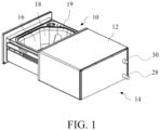
- FIG. 1 is a schematic three-dimensional view of a washing device according to some embodiments of the present invention.
- a washing device 10 includes: a box 12; a fluid assembly 14; and a washing cavity 16, accommodated in the box 12.
- the washing cavity 16 is replaceable, the washing cavity 16 is closable or openable, the washing cavity 16 is in communication with the fluid assembly 14 when closed, and the washing cavity 16 is disconnected from the fluid assembly 14 when opened.
- the washing device 10 may be a machine configured to wash clothes, fruits and vegetables, tableware, and the like.
- the box 12 may be substantially a square body.
- the fluid assembly 14 may be arranged in the box 12.
- the washing cavity 16 can accommodate to-be-washed articles (not shown).
- the washing cavity 16 may be in communication with the fluid assembly 14 when closed, and the fluid may enter or be discharged from the washing cavity 16 through the fluid assembly 14 for related washing operations.
- the washing cavity 16 is disconnected from the fluid assembly 14 when opened, so that the fluid cannot circulate between the washing cavity 16 and the fluid assembly 14, and it is also convenient for the washing cavity 16 to be taken out and replaced.
- the washing cavity 16 may be thoroughly cleaned after being taken out, which can guarantee cleanliness and health.
- Different washing cavities 16 may be replaced and used for different clothes, fruits and vegetables, tableware, and the like of different persons, which is helpful for classified washing.
- the washing device 10 may have various functions, and the washing cavity 16 may be small in size and low in cost, which is advantageous in terms of space and cost for an ordinary family.
- the fluid may include water, gas, washing additives, and the like.
- the washing cavity 16 includes a holding portion 18 configured to hold a liquid from the fluid assembly 14.
- the holding portion 18 has a closable opening 19.
- the form and closing manner of the opening 19 may be implemented in a plurality of manners.
- the opening 19 may autonomously contract to be closed, for example, edges are close to and fit each other, or the opening may be closed by, for example, a cover plate 20 ( FIG. 2 ).
- the holding portion 18 may have a structure substantially in the shape of a water tank.
- the opening 19 is open upward and may be closed by the cover plate 20.
- the holding portion 18 may hold the to-be-washed articles, and the liquid from the fluid assembly 14 is held in the holding portion 18 to participate in the washing, so that the to-be-washed articles can be washed.
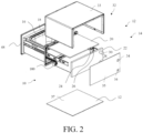
- FIG. 2 is a schematic exploded view of the washing device in FIG. 1 .
- the box 12 includes a cover plate 20 connected to the fluid assembly 14 and configured to cover the washing cavity 16.
- the fluid assembly 14 may provide a fluid to the washing cavity 16 through the cover plate 20 when the cover plate 20 covers the washing cavity 16, so as to perform washing operation in the washing cavity 16.
- the cover plate 20 is located at a top of the washing cavity 16.
- the washing device 10 can be simple in structure.
- the cover plate 20 may cover the washing cavity 16 from the top.
- the cover plate 20 is movable up and down relative to the washing cavity 16.
- the cover plate 20 may move downward to cover the washing cavity 16 and move upward to open the washing cavity 16.
- the fluid assembly 14 includes a passage assembly 22.
- the passage assembly includes: an input connecting tube 24 and an output connecting tube 26 respectively connected to the cover plate 20, and an input tube 28 and an output tube 30 configured to be respectively in fluid communication with the input connecting tube 24 and the output connecting tube 26.
- the fluid may enter the washing cavity 16 closed by the cover plate 20 through the input tube 28 and the input connecting tube 24, and may be discharged from the washing cavity 16 through the output connecting tube 26 and the output tube 30.
- the box 12 includes an enclosure 32.
- the enclosure includes through holes 34 corresponding to the input tube 28 and the output tube 30.
- the through holes 34 may be circular.
- the input tube 28 and the output tube 30 may correspond to shapes and sizes of the through holes 34.
- the enclosure 32 may include a main body 33 having a substantially U-shaped cross section, a rear portion 35 combined with the rear of the main body 33, and a lower part 37 combined with lower parts of the main body 33 and the rear portion 35.
- the enclosure 32 may surround the washing cavity 16 from five directions: up, left, right, back, and down.
- the through holes 34 may be arranged on the rear portion 35.
- the washing cavity 16 can move forward and backward relative to the enclosure 32.
- the input tube 28 and the output tube 30 may be located at the lower rear of the cover plate 20 and behind the washing cavity 16.
- FIG. 3 is a schematic diagram of a fluid passage of the washing device in FIG. 1 .
- the passage assembly 22 includes a branch 36 configured to be in fluid communication with a bottom of the washing cavity 16 and the output connecting tube 26.
- the branch 36 may output the fluid from the bottom of the washing cavity 16 and then output the fluid to the output connecting tube 26 connected to the cover plate 20.
- the passage assembly 22 includes a branch seal 38 arranged around the branch 36 to hermetically connect the branch 36 to the output connecting tube 26 when the cover plate 20 covers the washing cavity 16. In this way, this can be helpful in preventing leakage during fluid output.
- the seal 38 may be a sealing ring.
- the passage assembly 22 includes a washing seal 40 arranged between the cover plate 20 and the washing cavity 16 to form a sealed space in the washing cavity 16.
- the seal 40 may be the same as or different from the seal 38.
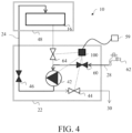
- FIG. 4 is a schematic diagram of another fluid passage of the washing device in FIG. 1 .
- the passage assembly 22 includes a suction device 42 configured to input a fluid into the washing cavity 16 or suck the fluid from the washing cavity 16.
- the suction device 42 may be a single suction element connected to complicated flow paths and valves, or may be composed of more than two suction elements.
- the suction element may be, for example, a pump.
- the passage assembly 22 includes a discharge valve 44 between the suction device 42 and the output tube 30, and an input valve 46 between the suction device 42 and the input connecting tube 24.
- the fluid may be discharged from the washing device 10 through the output tube 30 when the input valve 46 is closed and the discharge valve 44 is opened.
- the fluid may enter the washing cavity 16 again through the open input valve 46 and the input connecting tube 24 when the discharge valve 44 is closed, so as to be reused and save water resources.
- the washing cavity 16 is at least partially made of an elastic material or a flexible material.
- the washing cavity 16 may be deformed when the fluid is sucked by the suction device 42, which is helpful for squeezing washing, discharging the fluid, and drying.
- the cavity 16 is especially beneficial for washing clothes, and the mechanical force in the extrusion process is beneficial to the separation of stains from fabric fibers. Therefore, the cavity 16 has a better washing effect.
- FIG. 5 is a partial schematic exploded view of the washing device in FIG. 1 .
- FIG. 6 is a schematic three-dimensional assembly view of a washing device according to some embodiments.
- FIG. 7 is a schematic three-dimensional assembly view of the washing device in FIG. 5 .
- the washing device 10 includes a drawer assembly 48.
- the drawer assembly includes a frame 50 configured to accommodate the washing cavity 16 and a slide rail 52 movably connecting the frame 50 to the box 12.
- the frame 50 may have a drawer structure, and may be a substantially square body that is open upward.
- the washing cavity 16 may be put into the frame 50 downward from above and taken out upward from the frame 50.
- the slide rails 52 may be located at upper parts of two sides of the frame 50 as shown in FIG. 5 and FIG. 7 , or may be located at two sides of a bottom of the frame 50 as shown in FIG. 6 .
- the drawer assembly 48 is movable relative to the box 12.
- FIG. 8 is a schematic three-dimensional view of a washing device according to some other embodiments of the present invention. As shown in FIG. 8 , in some embodiments, one or more drawer assemblies 48 are arranged, and each of the drawer assemblies 48 accommodates one washing cavity 16.
- washing cavities 16 may be simultaneously used to wash different clothes of different persons, tableware, fruits and vegetables, or the like, thereby easily realizing the classified washing.
- different kinds of to-be-washed things may need to be equipped with corresponding different washing devices and/or washing cavities, but all washing cavities can be replaced based on the principle of the replaceable structure in this application.
- the washing cavity 16 of one of the drawer assemblies 48 may be taken out and replaced, so as to thoroughly clean the washing cavity 16, replace the washing cavity 16, and so on.
- each of the drawer assemblies 48 includes a panel 54, and a display device 56 is arranged on the panel 54.
- the panel 54 may be located at a position at a front side of the drawer assembly 48 and exposed outside the box 12.
- the display device 56 may display information from the washing device 10 or near-end and remote control devices such as a mobile phone and a computer that communicate with the washing device 10.
- the display device 56 is configured to display a closed or open state of the washing cavity 16.
- the fluid assembly 14 is arranged in the box 12 independently of the drawer assembly 48.
- the fluid assembly 14 may remain stationary.
- the washing cavity 16 of the drawer assembly 48 may be connected to the fluid assembly 14.
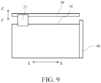
- FIG. 9 is a schematic side view of the washing device in FIG. 2 .
- a cover plate 20 connected to the fluid assembly 14 is arranged in the box 12.
- the cover plate 20 and the drawer assembly 48 are configured to be linked in such a way that the cover plate 20 moves toward the washing cavity 16 and is pressed against the washing cavity 16 when the drawer assembly 48 moves into the box 12, and the cover plate 20 leaves the washing cavity 16 when the drawer assembly 48 moves out of the box 12.
- the cover plate 20 and the drawer assembly 48 may be connected by a transmission device 21.
- the transmission device 21 may drive the cover plate 20 to move toward the washing cavity 16 in a Z-Z direction and is pressed against the washing cavity 16.
- the transmission device 21 may drive the cover plate 20 to leave the washing cavity 16 in the Z-Z direction, so as to open the washing cavity 16.
- the transmission device 21 may adopt various known implementations that can realize the above functions.
- the transmission device 21 may include a mechanical transmission device such as a gear and a chain.
- a mechanical transmission device such as a gear and a chain.
- the structure and transmission mode of the mechanical transmission part described in Chinese patent for invention with the Patent Application No. CN112709047A may be used as an embodiment of the transmission device 21 as a supplement to this description. Therefore, the details are not described herein again.
- the washing device 10 includes a control device 100.
- the control device 100 is configured to enable the fluid assembly 14 only when the washing cavity 16 is closed to input a fluid into the washing cavity 16 or suck the fluid from the washing cavity 16.
- the control device 100 may be arranged in the box 12 independently of the washing cavity 16.
- the control device 100 may include contact and non-contact plugins for transmitting information and energy, for example, an indicator light, a sensor, and/or an electromagnetic induction device, a magnet floating valve, a wireless power supply device, and the like.
- the control device 100 may enable the fluid assembly 14, open the first fluid valve 60 and the input valve 46, and close the second fluid valve 64 after the power supply 59 inputs electric power, so that the fluid can enter the input tube 28 from a water source such as a faucet 62, then pass through the first fluid valve 60, and be sucked by the suction device 42 through the input valve 46 and the input connecting tube 24 into the washing cavity 16.
- control device 100 may enable the fluid assembly 14, open the second fluid valve 64 and the discharge valve 44, and close the first fluid valve 60 and the input valve 46 after the power supply 59 inputs power, so that the fluid can be sucked by the suction device 42 and flow through the second fluid valve 64 and the discharge valve 44 from the washing cavity 16, and is discharged from the output tube 30.
- control device 100 may enable the fluid assembly 14, open the second fluid valve 64 and the input valve 46, and close the first fluid valve 60 and the discharge valve 44 after the power supply 59 inputs power, so that the fluid can be sucked by the suction device 42, flow through the second fluid valve 64 and the input valve 46 from the washing cavity 16, and enter the washing cavity 16 again.
Landscapes
- Engineering & Computer Science (AREA)
- Textile Engineering (AREA)
- Water Supply & Treatment (AREA)
- Mechanical Engineering (AREA)
- Food Science & Technology (AREA)
- Cleaning By Liquid Or Steam (AREA)
Abstract
Description
- The present invention relates to a washing device.
- The existing washing device such as a pulsator washing machine, a drum washing machine, a dish washing machine, or a food washing machine generally has a fixed and non-detachable washing cavity, which is difficult to be thoroughly cleaned, and is barely satisfactory in aspects such as cleaning and health protection. In particular, an ordinary washing machine generally includes a drum and a tub, and a lot of residues in the washing process may remain in an area between the drum and the tub, for example, sebum, dander, dirt, and the like. The user cannot touch the area and cannot clean the area thoroughly either, which may cause secondary pollution to clothes.
- In addition, especially for washing requirements, users often hope that different clothes can have independent washing spaces to avoid cross-contamination caused by mixed washing. For example, many users tend to wash baby clothes, underwear, socks, and the like separately, and even are unwilling to share the general washing machine for washing adult coats. In this case, users often wash these clothes by hand, or even buy one or more small washing machines to wash these clothes separately. In this way, either the housework burden or a space burden and a financial burden are increased.
- The present invention is intended to provide an improved washing device.
- For the above object, embodiments of the present invention relate to a washing device. The washing device includes: a box; a fluid assembly; and a washing cavity, accommodated in the box. The washing cavity is replaceable, the washing cavity is closable or openable, the washing cavity is in communication with the fluid assembly when closed, and the washing cavity is disconnected from the fluid assembly when opened.
- In this way, a user can remove the washing cavity for thorough cleaning, and in addition, the user only needs one washing device equipped with a plurality of washing cavities, so that all kinds of to-be-washed things can have exclusive washing cavities, thereby avoiding cross-contamination.
- In some embodiments, the washing cavity includes a holding portion configured to hold a liquid from the fluid assembly. In this way, this can be helpful in washing with the liquid in the holding portion.
- In some embodiments, the box includes a cover plate connected to the fluid assembly and configured to cover the washing cavity.
- In this way, this can be helpful in washing in the closed washing cavity. In some embodiments, the cover plate is located at a top of the washing cavity.
- In this way, the washing device can be simple in structure.
- In some embodiments, the cover plate is movable up and down relative to the washing cavity. In this way, this can be helpful in conveniently opening or closing the washing cavity.
- In some embodiments, the fluid assembly includes a passage assembly. The passage assembly includes: an input connecting tube and an output connecting tube respectively connected to the cover plate, and an input tube and an output tube configured to be respectively in fluid communication with the input connecting tube and the output connecting tube.
- In this way, this can be helpful for the fluid to enter and/or to be discharged from the washing cavity of the washing device.
- In some embodiments, the box includes an enclosure. The enclosure includes through holes corresponding to the input tube and the output tube. In this way, this can be helpful for the input tube and the output tube to extend through the enclosure through the through holes.
- In some embodiments, the passage assembly includes a branch configured to be in fluid communication with a bottom of the washing cavity and the output connecting tube.
- In this way, this can be helpful in efficiently outputting the fluid from the washing cavity.
- In some embodiments, the passage assembly includes a branch seal arranged around the branch to hermetically connect the branch to the output connecting tube when the cover plate covers the washing cavity.
- In this way, this can be helpful in preventing leakage during fluid output.
- In some embodiments, the passage assembly includes a washing seal arranged between the cover plate and the washing cavity to form a sealed space in the washing cavity.
- In this way, this can be helpful in preventing water leakage during washing, clothes from being thrown out, and impact on heat exchange and ventilation during drying.
- In some embodiments, the passage assembly includes a suction device configured to input a fluid into the washing cavity or suck the fluid from the washing cavity.
- In this way, this can be helpful for the fluid to efficiently enter and/or to be discharged from the washing cavity.
- In some embodiments, the passage assembly includes a discharge valve between the suction device and the output tube, and an input valve between the suction device and the input connecting tube.
- In this way, this can be helpful in controlling the output and/or input of the fluid from the washing cavity. In some embodiments, the washing cavity is at least partially made of an elastic material or a flexible material. In this way, this can be helpful for deformation of the washing cavity to squeeze washing and discharge fluid.
- In some embodiments, the washing device includes a drawer assembly. The drawer assembly includes a frame configured to accommodate the washing cavity and a slide rail movably connecting the frame to the box.
- In this way, this can be helpful for the washing cavity to move with the drawer assembly relative to the box.
- In some embodiments, one or more drawer assemblies are arranged, and each of the drawer assemblies accommodates one washing cavity.
- In this way, this can be helpful in washing in one or more drawer assemblies as needed. In some embodiments, each of the drawer assemblies includes a panel, and a display device is arranged on the panel.
- In this way, this can be helpful for the user to conveniently acquire information about the washing device.
- In some embodiments, the display device is configured to display a closed or open state of the washing cavity.
- In this way, this can be helpful for the user to acquire the closed or open state of the washing cavity, so as to ensure proper operation.
- In some embodiments, the fluid assembly is arranged in the box independently of the drawer assembly. In this way, this can be helpful in avoiding the mutual effect between the drawer assembly and the fluid assembly.
- In some embodiments, a cover plate connected to the fluid assembly is arranged in the box. The cover plate and the drawer assembly are configured to be linked in such a way that the cover plate moves toward the washing cavity and is pressed against the washing cavity when the drawer assembly moves into the box, and the cover plate leaves the washing cavity when the drawer assembly moves out of the box.
- In this way, this can be helpful in putting in and taking out clothes when the washing cavity is opened, and/or in washing when the washing cavity is closed.
- In some embodiments, the washing device includes a control device. The control device is configured to enable the fluid assembly only when the washing cavity is closed to input a fluid into the washing cavity or suck the fluid from the washing cavity.
- In this way, this can be helpful for the automatic, safe, and effective fluid flow of the washing device.
- The technical solutions of the embodiments in this application can be combined at will in a case that the technical conditions permit.
- This application is to be further described below with reference to the accompanying drawings. The same or similar reference numerals may be used in the figures to refer to the same or similar elements, devices, shapes, and structures in different embodiments, and descriptions of the same or similar elements, devices, shapes, structures, features, and effects in different embodiments and the same or similar elements, devices, shapes, structures, features, and effects in the prior art may also be omitted.
-
FIG. 1 is a schematic three-dimensional view of a washing device according to some embodiments of the present invention. -
FIG. 2 is a schematic exploded view of the washing device inFIG. 1 . -
FIG. 3 is a schematic diagram of a fluid passage of the washing device inFIG. 1 . -
FIG. 4 is a schematic diagram of another fluid passage of the washing device inFIG. 1 . -
FIG. 5 is a partial schematic exploded view of the washing device inFIG. 1 . -
FIG. 6 is a schematic three-dimensional assembly view of a washing device according to some embodiments. -
FIG. 7 is a schematic three-dimensional assembly view of the washing device inFIG. 5 . -
FIG. 8 is a schematic three-dimensional view of a washing device according to some other embodiments of the present invention. -
FIG. 9 is a schematic side view of the washing device inFIG. 2 . -
FIG. 1 is a schematic three-dimensional view of a washing device according to some embodiments of the present invention. As shown inFIG. 1 , embodiments of the present invention relate to awashing device 10. The washing device includes: abox 12; afluid assembly 14; and awashing cavity 16, accommodated in thebox 12. Thewashing cavity 16 is replaceable, thewashing cavity 16 is closable or openable, thewashing cavity 16 is in communication with thefluid assembly 14 when closed, and thewashing cavity 16 is disconnected from thefluid assembly 14 when opened. - In this way, this can facilitate thorough cleaning of the
washing cavity 16, classified washing, and the like. - The
washing device 10 may be a machine configured to wash clothes, fruits and vegetables, tableware, and the like. - The
box 12 may be substantially a square body. - The
fluid assembly 14 may be arranged in thebox 12. - The
washing cavity 16 can accommodate to-be-washed articles (not shown). Thewashing cavity 16 may be in communication with thefluid assembly 14 when closed, and the fluid may enter or be discharged from thewashing cavity 16 through thefluid assembly 14 for related washing operations. Thewashing cavity 16 is disconnected from thefluid assembly 14 when opened, so that the fluid cannot circulate between thewashing cavity 16 and thefluid assembly 14, and it is also convenient for thewashing cavity 16 to be taken out and replaced. - The
washing cavity 16 may be thoroughly cleaned after being taken out, which can guarantee cleanliness and health. -
Different washing cavities 16 may be replaced and used for different clothes, fruits and vegetables, tableware, and the like of different persons, which is helpful for classified washing. Thewashing device 10 may have various functions, and thewashing cavity 16 may be small in size and low in cost, which is advantageous in terms of space and cost for an ordinary family. - The fluid may include water, gas, washing additives, and the like.
- In some embodiments, the
washing cavity 16 includes a holdingportion 18 configured to hold a liquid from thefluid assembly 14. - In this way, this can be helpful in washing with the liquid in the holding
portion 18. The holdingportion 18 has aclosable opening 19. The form and closing manner of theopening 19 may be implemented in a plurality of manners. For example, theopening 19 may autonomously contract to be closed, for example, edges are close to and fit each other, or the opening may be closed by, for example, a cover plate 20 (FIG. 2 ). - In the embodiment shown in the accompanying drawing, the holding
portion 18 may have a structure substantially in the shape of a water tank. Theopening 19 is open upward and may be closed by thecover plate 20. The holdingportion 18 may hold the to-be-washed articles, and the liquid from thefluid assembly 14 is held in the holdingportion 18 to participate in the washing, so that the to-be-washed articles can be washed. -
FIG. 2 is a schematic exploded view of the washing device inFIG. 1 . As shown inFIG. 2 , in some embodiments, thebox 12 includes acover plate 20 connected to thefluid assembly 14 and configured to cover thewashing cavity 16. - In this way, this can be helpful in washing in the
closed washing cavity 16. - The
fluid assembly 14 may provide a fluid to thewashing cavity 16 through thecover plate 20 when thecover plate 20 covers thewashing cavity 16, so as to perform washing operation in thewashing cavity 16. - In some embodiments, the
cover plate 20 is located at a top of thewashing cavity 16. - In this way, the
washing device 10 can be simple in structure. - The
cover plate 20 may cover thewashing cavity 16 from the top. - In some embodiments, the
cover plate 20 is movable up and down relative to thewashing cavity 16. - In this way, this can be helpful in conveniently opening or closing the
washing cavity 16. - For example, the
cover plate 20 may move downward to cover thewashing cavity 16 and move upward to open thewashing cavity 16. - In some embodiments, the
fluid assembly 14 includes apassage assembly 22. The passage assembly includes: aninput connecting tube 24 and anoutput connecting tube 26 respectively connected to thecover plate 20, and aninput tube 28 and anoutput tube 30 configured to be respectively in fluid communication with theinput connecting tube 24 and theoutput connecting tube 26. - In this way, this can be helpful for the fluid to enter and/or to be discharged from the
washing cavity 16 of thewashing device 10. - The fluid may enter the
washing cavity 16 closed by thecover plate 20 through theinput tube 28 and theinput connecting tube 24, and may be discharged from thewashing cavity 16 through theoutput connecting tube 26 and theoutput tube 30. - In some embodiments, the
box 12 includes anenclosure 32. The enclosure includes throughholes 34 corresponding to theinput tube 28 and theoutput tube 30. - In this way, this can be helpful for the
input tube 28 and theoutput tube 30 to extend through theenclosure 32 through the through holes 34. - The through holes 34 may be circular. The
input tube 28 and theoutput tube 30 may correspond to shapes and sizes of the through holes 34. - The
enclosure 32 may include amain body 33 having a substantially U-shaped cross section, arear portion 35 combined with the rear of themain body 33, and alower part 37 combined with lower parts of themain body 33 and therear portion 35. Theenclosure 32 may surround thewashing cavity 16 from five directions: up, left, right, back, and down. The through holes 34 may be arranged on therear portion 35. Thewashing cavity 16 can move forward and backward relative to theenclosure 32. Theinput tube 28 and theoutput tube 30 may be located at the lower rear of thecover plate 20 and behind thewashing cavity 16. - For the terms such as "up", "left", "right", "rear", "down" and "front" in this application, reference may be made to the orientation and relationship in the accompanying drawings or the orientation and relationship during actual use of the
washing device 10. -
FIG. 3 is a schematic diagram of a fluid passage of the washing device inFIG. 1 . As shown inFIG. 3 , in some embodiments, thepassage assembly 22 includes abranch 36 configured to be in fluid communication with a bottom of thewashing cavity 16 and theoutput connecting tube 26. - In this way, this can be helpful in efficiently outputting the fluid from the
washing cavity 16. - The
branch 36 may output the fluid from the bottom of thewashing cavity 16 and then output the fluid to theoutput connecting tube 26 connected to thecover plate 20. - In some embodiments, the
passage assembly 22 includes abranch seal 38 arranged around thebranch 36 to hermetically connect thebranch 36 to theoutput connecting tube 26 when thecover plate 20 covers thewashing cavity 16. In this way, this can be helpful in preventing leakage during fluid output. - The
seal 38 may be a sealing ring. - In some embodiments, the
passage assembly 22 includes awashing seal 40 arranged between thecover plate 20 and thewashing cavity 16 to form a sealed space in thewashing cavity 16. - In this way, this can be helpful in preventing water leakage during washing, clothes from being thrown out, and impact on heat exchange and ventilation during drying.
- The
seal 40 may be the same as or different from theseal 38. -
FIG. 4 is a schematic diagram of another fluid passage of the washing device inFIG. 1 . As shown inFIG. 4 , in some embodiments, thepassage assembly 22 includes asuction device 42 configured to input a fluid into thewashing cavity 16 or suck the fluid from thewashing cavity 16. - In this way, this can be helpful for the fluid to efficiently enter and/or to be discharged from the
washing cavity 16. - The
suction device 42 may be a single suction element connected to complicated flow paths and valves, or may be composed of more than two suction elements. The suction element may be, for example, a pump. - In some embodiments, the
passage assembly 22 includes adischarge valve 44 between thesuction device 42 and theoutput tube 30, and aninput valve 46 between thesuction device 42 and theinput connecting tube 24. - In this way, this can be helpful in controlling the discharge of the fluid from the
washing cavity 16 and the entry of the fluid into thewashing cavity 16. After the fluid is sucked out of thewashing cavity 16 by thesuction device 42, the fluid may be discharged from thewashing device 10 through theoutput tube 30 when theinput valve 46 is closed and thedischarge valve 44 is opened. Alternatively, after the fluid is sucked out of thewashing cavity 16 by thesuction device 42, the fluid may enter thewashing cavity 16 again through theopen input valve 46 and theinput connecting tube 24 when thedischarge valve 44 is closed, so as to be reused and save water resources. - In some embodiments, the
washing cavity 16 is at least partially made of an elastic material or a flexible material. - In this way, this can be helpful for deformation of the
washing cavity 16 to squeeze washing and discharge fluid. - During use, the
washing cavity 16 may be deformed when the fluid is sucked by thesuction device 42, which is helpful for squeezing washing, discharging the fluid, and drying. Thecavity 16 is especially beneficial for washing clothes, and the mechanical force in the extrusion process is beneficial to the separation of stains from fabric fibers. Therefore, thecavity 16 has a better washing effect. -
FIG. 5 is a partial schematic exploded view of the washing device inFIG. 1 .FIG. 6 is a schematic three-dimensional assembly view of a washing device according to some embodiments.FIG. 7 is a schematic three-dimensional assembly view of the washing device inFIG. 5 . As shown inFIG. 5 to FIG. 7 , in some embodiments, thewashing device 10 includes adrawer assembly 48. The drawer assembly includes aframe 50 configured to accommodate thewashing cavity 16 and aslide rail 52 movably connecting theframe 50 to thebox 12. - In this way, this can be helpful for the
frame 50 to support thewashing cavity 16 and enter and exit thebox 12 along theslide rail 52. - The
frame 50 may have a drawer structure, and may be a substantially square body that is open upward. Thewashing cavity 16 may be put into theframe 50 downward from above and taken out upward from theframe 50. The slide rails 52 may be located at upper parts of two sides of theframe 50 as shown inFIG. 5 andFIG. 7 , or may be located at two sides of a bottom of theframe 50 as shown inFIG. 6 . Thedrawer assembly 48 is movable relative to thebox 12. -
FIG. 8 is a schematic three-dimensional view of a washing device according to some other embodiments of the present invention. As shown inFIG. 8 , in some embodiments, one ormore drawer assemblies 48 are arranged, and each of thedrawer assemblies 48 accommodates onewashing cavity 16. - In this way, this can be helpful for classified washing and thorough cleaning of the
washing cavity 16. - When the
washing device 10 including a plurality ofdrawer assemblies 48 is used,different washing cavities 16 may be simultaneously used to wash different clothes of different persons, tableware, fruits and vegetables, or the like, thereby easily realizing the classified washing. Certainly, it may be understood that different kinds of to-be-washed things may need to be equipped with corresponding different washing devices and/or washing cavities, but all washing cavities can be replaced based on the principle of the replaceable structure in this application. - The
washing cavity 16 of one of thedrawer assemblies 48 may be taken out and replaced, so as to thoroughly clean thewashing cavity 16, replace thewashing cavity 16, and so on. - In some embodiments, each of the
drawer assemblies 48 includes apanel 54, and adisplay device 56 is arranged on thepanel 54. - In this way, this can be helpful in conveniently acquiring information about the
washing device 10. - The
panel 54 may be located at a position at a front side of thedrawer assembly 48 and exposed outside thebox 12. Thedisplay device 56 may display information from thewashing device 10 or near-end and remote control devices such as a mobile phone and a computer that communicate with thewashing device 10. - In some embodiments, the
display device 56 is configured to display a closed or open state of thewashing cavity 16. - In this way, this can be helpful in acquiring the closed or open state of the
washing cavity 16, ensuring proper operation, and providing a reminder when thewashing cavity 16 is in an incorrect position to avoid misoperation. - In some embodiments, the
fluid assembly 14 is arranged in thebox 12 independently of thedrawer assembly 48. - In this way, this can be helpful in avoiding the mutual effect between the
drawer assembly 48 and thefluid assembly 14. - When the
drawer assembly 48 moves relative to thebox 12, thefluid assembly 14 may remain stationary. When thedrawer assembly 48 enters the correct position of thebox 12, thewashing cavity 16 of thedrawer assembly 48 may be connected to thefluid assembly 14. -
FIG. 9 is a schematic side view of the washing device inFIG. 2 . Referring toFIG. 2 andFIG. 9 , in some embodiments, acover plate 20 connected to thefluid assembly 14 is arranged in thebox 12. Thecover plate 20 and thedrawer assembly 48 are configured to be linked in such a way that thecover plate 20 moves toward thewashing cavity 16 and is pressed against thewashing cavity 16 when thedrawer assembly 48 moves into thebox 12, and thecover plate 20 leaves thewashing cavity 16 when thedrawer assembly 48 moves out of thebox 12. - In this way, this can be helpful for automatic opening and closing of the
washing cavity 16 without manual operation. - For example, the
cover plate 20 and thedrawer assembly 48 may be connected by atransmission device 21. When thedrawer assembly 48 moves into thebox 12 in an X-X direction, thetransmission device 21 may drive thecover plate 20 to move toward thewashing cavity 16 in a Z-Z direction and is pressed against thewashing cavity 16. When thedrawer assembly 48 moves out of thebox 12 in the X-X direction, thetransmission device 21 may drive thecover plate 20 to leave thewashing cavity 16 in the Z-Z direction, so as to open thewashing cavity 16. - The
transmission device 21 may adopt various known implementations that can realize the above functions. Thetransmission device 21 may include a mechanical transmission device such as a gear and a chain. Specifically, for example, the structure and transmission mode of the mechanical transmission part described in Chinese patent for invention with the Patent Application No.CN112709047A may be used as an embodiment of thetransmission device 21 as a supplement to this description. Therefore, the details are not described herein again. - Referring to
FIG. 2 andFIG. 4 , in some embodiments, thewashing device 10 includes acontrol device 100. Thecontrol device 100 is configured to enable thefluid assembly 14 only when thewashing cavity 16 is closed to input a fluid into thewashing cavity 16 or suck the fluid from thewashing cavity 16. - In this way, this can be helpful for the automatic, safe, and effective fluid flow of the
washing device 10. - The
control device 100 may be arranged in thebox 12 independently of thewashing cavity 16. Thecontrol device 100 may include contact and non-contact plugins for transmitting information and energy, for example, an indicator light, a sensor, and/or an electromagnetic induction device, a magnet floating valve, a wireless power supply device, and the like. - When the
washing cavity 16 is closed, thecontrol device 100 may enable thefluid assembly 14, open the firstfluid valve 60 and theinput valve 46, and close thesecond fluid valve 64 after thepower supply 59 inputs electric power, so that the fluid can enter theinput tube 28 from a water source such as afaucet 62, then pass through the firstfluid valve 60, and be sucked by thesuction device 42 through theinput valve 46 and theinput connecting tube 24 into thewashing cavity 16. - Alternatively, when the
washing cavity 16 is closed, thecontrol device 100 may enable thefluid assembly 14, open thesecond fluid valve 64 and thedischarge valve 44, and close the firstfluid valve 60 and theinput valve 46 after thepower supply 59 inputs power, so that the fluid can be sucked by thesuction device 42 and flow through thesecond fluid valve 64 and thedischarge valve 44 from thewashing cavity 16, and is discharged from theoutput tube 30. - Alternatively, when the
washing cavity 16 is closed, thecontrol device 100 may enable thefluid assembly 14, open thesecond fluid valve 64 and theinput valve 46, and close the firstfluid valve 60 and thedischarge valve 44 after thepower supply 59 inputs power, so that the fluid can be sucked by thesuction device 42, flow through thesecond fluid valve 64 and theinput valve 46 from thewashing cavity 16, and enter thewashing cavity 16 again. - The various specific implementations described above and shown in the accompanying drawings are only used to describe the present invention, but not the entirety of the invention. Within the scope of the basic technical idea of the present invention, any form of changes made to the present invention by a person of ordinary skill in the related art shall fall within the protection scope of the present invention.
Claims (20)
- A washing device (10), characterized by comprising:a box (12);a fluid assembly (14); anda washing cavity (16), accommodated in the box (12), wherein the washing cavity (16) is replaceable, the washing cavity (16) is closable or openable, the washing cavity (16) is in communication with the fluid assembly (14) when closed, and the washing cavity (16) is disconnected from the fluid assembly (14) when opened.
- The washing device (10) according to claim 1, characterized in that the washing cavity (16) comprises a holding portion (18) configured to hold a liquid from the fluid assembly (14).
- The washing device (10) according to claim 1, characterized in that the box (12) comprises a cover plate (20) connected to the fluid assembly (14) and configured to cover the washing cavity (16).
- The washing device (10) according to claim 3, characterized in that the cover plate (20) is located at a top of the washing cavity (16).
- The washing device (10) according to claim 3, characterized in that the cover plate (20) is movable up and down relative to the washing cavity (16).
- The washing device (10) according to claim 3, characterized in that the fluid assembly (14) comprises a passage assembly (22), and the passage assembly comprises: an input connecting tube (24) and an output connecting tube (26) respectively connected to the cover plate (20), and an input tube (28) and an output tube (30) configured to be respectively in fluid communication with the input connecting tube (24) and the output connecting tube (26).
- The washing device (10) according to claim 6, characterized in that the box (12) comprises an enclosure (32), and the enclosure comprises through holes (34) corresponding to the input tube (28) and the output tube (30).
- The washing device (10) according to claim 6, characterized in that the passage assembly (22) comprises a branch (36) configured to be in fluid communication with a bottom of the washing cavity (16) and the output connecting tube (26).
- The washing device (10) according to claim 8, characterized in that the passage assembly (22) comprises a branch seal (38) arranged around the branch (36) to hermetically connect the branch (36) to the output connecting tube (26) when the cover plate (20) covers the washing cavity (16).
- The washing device (10) according to claim 6, characterized in that the passage assembly (22) comprises a washing seal (40) arranged between the cover plate (20) and the washing cavity (16) to form a sealed space in the washing cavity (16).
- The washing device (10) according to claim 6, characterized in that the passage assembly (22) comprises a suction device (42) configured to input a fluid into the washing cavity (16) or suck the fluid from the washing cavity (16).
- The washing device (10) according to claim 11, characterized in that the passage assembly (22) comprises a discharge valve (44) between the suction device (42) and the output tube (30) and an input valve (46) between the suction device (42) and the input connecting tube (24).
- The washing device (10) according to claim 1, characterized in that the washing cavity (16) is at least partially made of an elastic material or a flexible material.
- The washing device (10) according to claim 1, characterized by comprising a drawer assembly (48), wherein the drawer assembly comprises a frame (50) configured to accommodate the washing cavity (16) and a slide rail (52) movably connecting the frame (50) to the box (12).
- The washing device (10) according to claim 14, characterized in that one or more drawer assemblies (48) are arranged, and each of the drawer assemblies (48) accommodates one washing cavity (16).
- The washing device (10) according to claim 14, characterized in that the drawer assembly (48) comprises a panel (54), and a display device (56) is arranged on the panel (54).
- The washing device (10) according to claim 16, characterized in that the display device (56) is configured to display a closed or open state of the washing cavity (16).
- The washing device (10) according to claim 14, characterized in that the fluid assembly (14) is arranged in the box (12) independently of the drawer assembly (48).
- The washing device (10) according to claim 14, characterized in that a cover plate (20) connected to the fluid assembly (14) is arranged in the box (12), wherein the cover plate (20) and the drawer assembly (48) are configured to be linked in such a way that the cover plate (20) moves toward the washing cavity (16) and is pressed against the washing cavity (16) when the drawer assembly (48) moves into the box (12), and the cover plate (20) leaves the washing cavity (16) when the drawer assembly (48) moves out of the box (12).
- The washing device (10) according to claim 1, characterized by comprising a control device (100), wherein the control device (100) is configured to enable the fluid assembly (14) only when the washing cavity (16) is closed to input a fluid into the washing cavity (16) or suck the fluid from the washing cavity (16).
Applications Claiming Priority (1)
| Application Number | Priority Date | Filing Date | Title |
|---|---|---|---|
| CN202210423472.2A CN116971151A (en) | 2022-04-21 | 2022-04-21 | washing device |
Publications (1)
| Publication Number | Publication Date |
|---|---|
| EP4265833A1 true EP4265833A1 (en) | 2023-10-25 |
Family
ID=85778764
Family Applications (1)
| Application Number | Title | Priority Date | Filing Date |
|---|---|---|---|
| EP23164707.4A Withdrawn EP4265833A1 (en) | 2022-04-21 | 2023-03-28 | Washing device |
Country Status (2)
| Country | Link |
|---|---|
| EP (1) | EP4265833A1 (en) |
| CN (1) | CN116971151A (en) |
Citations (4)
| Publication number | Priority date | Publication date | Assignee | Title |
|---|---|---|---|---|
| WO2015115730A1 (en) * | 2014-01-29 | 2015-08-06 | 삼성전자주식회사 | Washing machine and wash water supplying device |
| EP2949803A1 (en) * | 2014-05-30 | 2015-12-02 | LG Electronics Inc. | Laundry treatment apparatus |
| CN112709047A (en) | 2019-10-24 | 2021-04-27 | 博西华电器(江苏)有限公司 | Drawer type clothes treatment device and composite washing machine |
| EP3964621A2 (en) * | 2014-05-30 | 2022-03-09 | LG Electronics Inc. | Laundry treatment apparatus |
-
2022
- 2022-04-21 CN CN202210423472.2A patent/CN116971151A/en active Pending
-
2023
- 2023-03-28 EP EP23164707.4A patent/EP4265833A1/en not_active Withdrawn
Patent Citations (4)
| Publication number | Priority date | Publication date | Assignee | Title |
|---|---|---|---|---|
| WO2015115730A1 (en) * | 2014-01-29 | 2015-08-06 | 삼성전자주식회사 | Washing machine and wash water supplying device |
| EP2949803A1 (en) * | 2014-05-30 | 2015-12-02 | LG Electronics Inc. | Laundry treatment apparatus |
| EP3964621A2 (en) * | 2014-05-30 | 2022-03-09 | LG Electronics Inc. | Laundry treatment apparatus |
| CN112709047A (en) | 2019-10-24 | 2021-04-27 | 博西华电器(江苏)有限公司 | Drawer type clothes treatment device and composite washing machine |
Also Published As
| Publication number | Publication date |
|---|---|
| CN116971151A (en) | 2023-10-31 |
Similar Documents
| Publication | Publication Date | Title |
|---|---|---|
| EP3354184B1 (en) | In-sink located dishwasher | |
| CN111315263B (en) | Closed culinary art cavity and machine of cooking | |
| EP2611349B1 (en) | A dishwasher | |
| KR101270538B1 (en) | A tableware washing machine | |
| US11486079B2 (en) | Laundry box and machine for separately washing clothes | |
| US9861257B2 (en) | Detergent dispenser module for a dishwashing appliance | |
| WO2019024896A1 (en) | Washing machine with auxiliary washing unit | |
| US3759276A (en) | Drawer type pan washing machine | |
| CN104983329A (en) | A sliding type vegetable washing device | |
| WO1991005506A1 (en) | Dish washing machine with a vertically movable door blade | |
| KR101677412B1 (en) | A drainage cap for sink | |
| CN116971151A (en) | washing device | |
| CN208447511U (en) | A kind of dish-washing machine | |
| US2764169A (en) | Dishwashing machine | |
| CN111188154A (en) | a washing device | |
| CN205893694U (en) | Laundry treating machine | |
| CN213993495U (en) | Sealing element, cleaning chamber comprising same and dish washing machine | |
| CN212925480U (en) | a washing device | |
| CN208769716U (en) | A kind of dish-washing machine | |
| KR20230085690A (en) | Dishwasher by using ultrasonic wave | |
| CN217510446U (en) | Dish washing machine with water guide cover body | |
| CN210055629U (en) | Automatic cleaning's machine of cooking to unloading mechanism and frying pan is realized | |
| CN221654206U (en) | A new type of tableware washing machine | |
| CN213696794U (en) | Dish washer upper shield and dish washer | |
| CN222160689U (en) | Cleaning and laundry equipment |
Legal Events
| Date | Code | Title | Description |
|---|---|---|---|
| STAA | Information on the status of an ep patent application or granted ep patent |
Free format text: STATUS: THE APPLICATION HAS BEEN PUBLISHED |
|
| PUAI | Public reference made under article 153(3) epc to a published international application that has entered the european phase |
Free format text: ORIGINAL CODE: 0009012 |
|
| AK | Designated contracting states |
Kind code of ref document: A1 Designated state(s): AL AT BE BG CH CY CZ DE DK EE ES FI FR GB GR HR HU IE IS IT LI LT LU LV MC ME MK MT NL NO PL PT RO RS SE SI SK SM TR |
|
| STAA | Information on the status of an ep patent application or granted ep patent |
Free format text: STATUS: REQUEST FOR EXAMINATION WAS MADE |
|
| 17P | Request for examination filed |
Effective date: 20240425 |
|
| RBV | Designated contracting states (corrected) |
Designated state(s): AL AT BE BG CH CY CZ DE DK EE ES FI FR GB GR HR HU IE IS IT LI LT LU LV MC ME MK MT NL NO PL PT RO RS SE SI SK SM TR |
|
| GRAP | Despatch of communication of intention to grant a patent |
Free format text: ORIGINAL CODE: EPIDOSNIGR1 |
|
| STAA | Information on the status of an ep patent application or granted ep patent |
Free format text: STATUS: GRANT OF PATENT IS INTENDED |
|
| RIC1 | Information provided on ipc code assigned before grant |
Ipc: D06F 39/14 20060101ALN20240705BHEP Ipc: D06F 39/08 20060101ALN20240705BHEP Ipc: D06F 31/00 20060101ALN20240705BHEP Ipc: D06F 17/00 20060101AFI20240705BHEP |
|
| INTG | Intention to grant announced |
Effective date: 20240723 |
|
| RIN1 | Information on inventor provided before grant (corrected) |
Inventor name: LIU, SHUAI Inventor name: YANG, FAN Inventor name: ZHANG, SHURONG |
|
| STAA | Information on the status of an ep patent application or granted ep patent |
Free format text: STATUS: THE APPLICATION IS DEEMED TO BE WITHDRAWN |
|
| 18D | Application deemed to be withdrawn |
Effective date: 20241126 |