EP4265711A1 - Thermal cycler and genetic testing equipment - Google Patents
Thermal cycler and genetic testing equipment Download PDFInfo
- Publication number
- EP4265711A1 EP4265711A1 EP20966027.3A EP20966027A EP4265711A1 EP 4265711 A1 EP4265711 A1 EP 4265711A1 EP 20966027 A EP20966027 A EP 20966027A EP 4265711 A1 EP4265711 A1 EP 4265711A1
- Authority
- EP
- European Patent Office
- Prior art keywords
- thermal cycler
- thermoelectric conversion
- temperature control
- temperature
- control block
- Prior art date
- Legal status (The legal status is an assumption and is not a legal conclusion. Google has not performed a legal analysis and makes no representation as to the accuracy of the status listed.)
- Pending
Links
Images


Classifications
-
- B—PERFORMING OPERATIONS; TRANSPORTING
- B01—PHYSICAL OR CHEMICAL PROCESSES OR APPARATUS IN GENERAL
- B01L—CHEMICAL OR PHYSICAL LABORATORY APPARATUS FOR GENERAL USE
- B01L7/00—Heating or cooling apparatus; Heat insulating devices
- B01L7/52—Heating or cooling apparatus; Heat insulating devices with provision for submitting samples to a predetermined sequence of different temperatures, e.g. for treating nucleic acid samples
-
- B—PERFORMING OPERATIONS; TRANSPORTING
- B01—PHYSICAL OR CHEMICAL PROCESSES OR APPARATUS IN GENERAL
- B01L—CHEMICAL OR PHYSICAL LABORATORY APPARATUS FOR GENERAL USE
- B01L2200/00—Solutions for specific problems relating to chemical or physical laboratory apparatus
- B01L2200/06—Fluid handling related problems
- B01L2200/0647—Handling flowable solids, e.g. microscopic beads, cells, particles
- B01L2200/0663—Stretching or orienting elongated molecules or particles
-
- B—PERFORMING OPERATIONS; TRANSPORTING
- B01—PHYSICAL OR CHEMICAL PROCESSES OR APPARATUS IN GENERAL
- B01L—CHEMICAL OR PHYSICAL LABORATORY APPARATUS FOR GENERAL USE
- B01L2200/00—Solutions for specific problems relating to chemical or physical laboratory apparatus
- B01L2200/12—Specific details about manufacturing devices
-
- B—PERFORMING OPERATIONS; TRANSPORTING
- B01—PHYSICAL OR CHEMICAL PROCESSES OR APPARATUS IN GENERAL
- B01L—CHEMICAL OR PHYSICAL LABORATORY APPARATUS FOR GENERAL USE
- B01L2200/00—Solutions for specific problems relating to chemical or physical laboratory apparatus
- B01L2200/14—Process control and prevention of errors
- B01L2200/143—Quality control, feedback systems
- B01L2200/147—Employing temperature sensors
-
- B—PERFORMING OPERATIONS; TRANSPORTING
- B01—PHYSICAL OR CHEMICAL PROCESSES OR APPARATUS IN GENERAL
- B01L—CHEMICAL OR PHYSICAL LABORATORY APPARATUS FOR GENERAL USE
- B01L2200/00—Solutions for specific problems relating to chemical or physical laboratory apparatus
- B01L2200/16—Reagents, handling or storing thereof
-
- B—PERFORMING OPERATIONS; TRANSPORTING
- B01—PHYSICAL OR CHEMICAL PROCESSES OR APPARATUS IN GENERAL
- B01L—CHEMICAL OR PHYSICAL LABORATORY APPARATUS FOR GENERAL USE
- B01L2300/00—Additional constructional details
- B01L2300/02—Identification, exchange or storage of information
- B01L2300/025—Displaying results or values with integrated means
-
- B—PERFORMING OPERATIONS; TRANSPORTING
- B01—PHYSICAL OR CHEMICAL PROCESSES OR APPARATUS IN GENERAL
- B01L—CHEMICAL OR PHYSICAL LABORATORY APPARATUS FOR GENERAL USE
- B01L2300/00—Additional constructional details
- B01L2300/06—Auxiliary integrated devices, integrated components
- B01L2300/0627—Sensor or part of a sensor is integrated
- B01L2300/0645—Electrodes
-
- B—PERFORMING OPERATIONS; TRANSPORTING
- B01—PHYSICAL OR CHEMICAL PROCESSES OR APPARATUS IN GENERAL
- B01L—CHEMICAL OR PHYSICAL LABORATORY APPARATUS FOR GENERAL USE
- B01L2300/00—Additional constructional details
- B01L2300/06—Auxiliary integrated devices, integrated components
- B01L2300/0627—Sensor or part of a sensor is integrated
- B01L2300/0663—Whole sensors
-
- B—PERFORMING OPERATIONS; TRANSPORTING
- B01—PHYSICAL OR CHEMICAL PROCESSES OR APPARATUS IN GENERAL
- B01L—CHEMICAL OR PHYSICAL LABORATORY APPARATUS FOR GENERAL USE
- B01L2300/00—Additional constructional details
- B01L2300/12—Specific details about materials
-
- B—PERFORMING OPERATIONS; TRANSPORTING
- B01—PHYSICAL OR CHEMICAL PROCESSES OR APPARATUS IN GENERAL
- B01L—CHEMICAL OR PHYSICAL LABORATORY APPARATUS FOR GENERAL USE
- B01L2300/00—Additional constructional details
- B01L2300/18—Means for temperature control
- B01L2300/1805—Conductive heating, heat from thermostatted solids is conducted to receptacles, e.g. heating plates, blocks
- B01L2300/1822—Conductive heating, heat from thermostatted solids is conducted to receptacles, e.g. heating plates, blocks using Peltier elements
-
- B—PERFORMING OPERATIONS; TRANSPORTING
- B01—PHYSICAL OR CHEMICAL PROCESSES OR APPARATUS IN GENERAL
- B01L—CHEMICAL OR PHYSICAL LABORATORY APPARATUS FOR GENERAL USE
- B01L2300/00—Additional constructional details
- B01L2300/18—Means for temperature control
- B01L2300/1838—Means for temperature control using fluid heat transfer medium
- B01L2300/1844—Means for temperature control using fluid heat transfer medium using fans
-
- B—PERFORMING OPERATIONS; TRANSPORTING
- B01—PHYSICAL OR CHEMICAL PROCESSES OR APPARATUS IN GENERAL
- B01L—CHEMICAL OR PHYSICAL LABORATORY APPARATUS FOR GENERAL USE
- B01L2300/00—Additional constructional details
- B01L2300/18—Means for temperature control
- B01L2300/1883—Means for temperature control using thermal insulation
-
- B—PERFORMING OPERATIONS; TRANSPORTING
- B01—PHYSICAL OR CHEMICAL PROCESSES OR APPARATUS IN GENERAL
- B01L—CHEMICAL OR PHYSICAL LABORATORY APPARATUS FOR GENERAL USE
- B01L9/00—Supporting devices; Holding devices
- B01L9/06—Test-tube stands; Test-tube holders
Definitions
- the present invention relates to a thermal cycler, and more particularly, to a thermal cycler used for a genetic inspection apparatus.
- Some genetic inspection apparatuses include nucleic acid amplification devices using a polymerase chain reaction (PCR) method.
- the nucleic acid amplification devices include thermal cyclers to adjust temperatures of reaction liquids in which reagents and samples originated from living bodies extracted from blood, saliva, urine, or the like are mixed.
- a cycle formed by thermal denaturation, annealing, and expansion steps of a nucleic acid is repeated dozens of times to amplify one molecule to millions of molecules.
- the nucleic acid amplification process is implemented by repeating a temperature adjustment cycle (hereinafter referred to as a "temperature control cycle") at which a temperature of a reaction liquid including a nucleic acid is controlled in a range of, for example, about 65°C to 95°C.
- a genetic inspection apparatus is required to have performance capable of accelerating temperature adjustment and shortening a time required to amplify nucleic acids to shorten an inspection time or increasing the number of processes within a predetermined time. Therefore, a technology for heating and cooling a temperature of the reaction liquid at a high speed is required in a thermal cycler used for a genetic inspection apparatus.
- a time required to change a temperature of an object is characterized by a heat transfer amount transferred to the object which changes temperature and a heat capacity and thermal conductivity of the object.
- a thermal cycler used for a general genetic inspection apparatus includes a temperature adjustment block (a temperature control block) in which a reaction vessel where a reaction liquid is input is installed and a thermoelectric conversion module configured by sandwiching an electric circuit (a thermoelectric conversion unit) including a thermoelectric semiconductor and an electrode between insulating substrates.
- a temperature of the temperature control block storing a reaction liquid is heated or cooled by adjusting heat generation, heat absorption or joule heating obtained through a thermoelectric conversion action by changing a current or a voltage applied to a thermoelectric conversion module.
- To accelerate a temperature control cycle it is necessary to increase a value of a heat transfer amount of heating or cooling and decrease a heat capacity or thermal resistance of an object which changes a temperature.
- a supporter for many samples disclosed in PTL 1 includes a block of a unitary structure, a series of sample wells in the block, and a series of hollow portions in the block between the sample wells. A mass of the block is reduced by the hollow portions, a heat capacity is decreased, and a change in temperature is transferred to the samples fast.
- thermoelectric conversion modules of mass-market products configured with insulating substrates using alumina as a material are used in many cases.
- a ratio of the heat capacity caused from the insulating substrates configuring the thermoelectric conversion module has increased considerably in the heat capacity of the object which changes a temperature.
- An object of the present invention is to provide a thermal cycler which can heat or cool a reaction liquid rapidly and efficiently and has a long lifespan and provide a genetic inspection apparatus including the thermal cycler.
- a thermal cycler includes: a temperature adjustment block configured such that a reaction vessel storing a reaction liquid in which a sample and a reagent are mixed is installable; a thermoelectric conversion unit capable of performing heating and cooling; a temperature sensor configured to measure a temperature of the temperature adjustment block; an insulating substrate configured such that one surface contacts with the thermoelectric conversion unit; and a heat radiating unit provided on the other surface of the insulating substrate and configured to discharge heat of the thermoelectric conversion unit to the outside.
- a current or a voltage supplied to the thermoelectric conversion unit is controlled based on the temperature of the temperature adjustment block measured by the temperature sensor to heat and cool the temperature adjustment block.
- the thermoelectric conversion unit is sandwiched between the temperature adjustment block and the insulating substrate, and the temperature adjustment block is formed of an electrically insulating material and is installed to be in contact with the thermoelectric conversion unit.
- a genetic inspection apparatus includes the thermal cycler and a measurement unit configured to measure a fluorescent property of a reagent solution of which a temperature is adjusted by the thermal cycler.
- thermo cycler which can heat or cool a reaction liquid rapidly and efficiently and has a long lifespan
- a genetic inspection apparatus which includes the thermal cycler and can perform inspection in a short time
- a thermal cycler can heat or cool a temperature of a reaction liquid rapidly by reducing a heat capacity caused in an insulating substrate configuring a thermoelectric conversion module included in a thermal cycler according to the related art and reducing thermal resistance caused by a thermal interface material such as a thermal conductive grease interposed between a temperature control block and the insulating substrate.
- a genetic inspection apparatus includes the thermal cycler according to the invention.
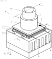
- Fig. 1 is a perspective view illustrating an outline of a configuration of a thermal cycler 20 according to the embodiment of the invention.
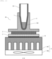
- Fig. 2 is a sectional view illustrating the outline of the configuration of the thermal cycler 20 according to the embodiment of the invention and corresponding to the line A-A of Fig. 1 .
- the thermal cycler 20 includes a temperature adjustment block 2 (hereinafter referred to as a "temperature control block 2"), a thermoelectric conversion unit 3, an insulating substrate 4, and a heat radiating unit 5.
- a reaction vessel 101 that contains a reaction liquid 102 can be installed.
- the temperature control block 2 may be configured to install the reaction vessel 101 in the recessed portion 1 or may be configured to place the reaction vessel 101 on the surface of the temperature adjustment block 2.
- the temperature control block 2 includes the recessed portion 1 where the reaction vessel 101 is installed.
- the temperature control block 2 is installed to be in contact with the thermoelectric conversion unit 3.
- the reaction liquid 102 includes a reagent and a sample including a nucleic acid.
- the thermoelectric conversion unit 3 is a temperature adjustment device capable of heating one surface and cooling the other surface by a thermoelectric conversion action and switches between heating and cooling surfaces according to a current flowing direction. Accordingly, the reaction liquid 102 contained in the reaction vessel 101 installed in the temperature control block 2 is heated and cooled.
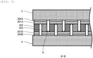
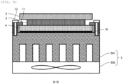
- Fig. 3 is a sectional view illustrating an outline of a configuration of the thermoelectric conversion unit 3 in the thermal cycler 20 according to the embodiment of the invention and corresponding to the line B-B of Fig. 1 .
- the thermoelectric conversion unit 3 includes at least electrodes 301A and 301B, a P-type semiconductor element 302, and an N-type semiconductor element 303.
- a pair of P-type semiconductor element 302 and N-type semiconductor element 303 are electrically connected in series by the electrodes 301.
- the P-type semiconductor element 302 and the N-type semiconductor element 303 are joined to the electrodes 301 by a solder 6.
- Lead wires 7A and 7B illustrated in Fig. 1 are connected to the electrodes 301.
- the thermoelectric conversion unit 3 heats one surface and cools the other surface by applying currents from the lead wires 7A and 7B.
- the thermoelectric conversion unit 3 can switch between heating and cooling of the reaction liquid 102 according to a direction of the applied current.
- a value of a current or a voltage applied to the thermoelectric conversion unit 3 is adjusted according to an output of the temperature sensor 8 and the temperature control block 2 is controlled according to a designated temperature.
- a metal plated layer 304A is applied to the surface of the temperature control block 2 and the electrode 301A is mounted on the metal plated layer 304A.
- a metal plated layer 304B is applied to the surface of the insulating substrate 4 and an electrode 301B is mounted on the metal plated layer 304B.
- the insulating substrate 4 is installed between the thermoelectric conversion unit 3 and the heat radiating unit 5 to be in contact with the thermoelectric conversion unit 3 and the heat radiating unit 5.
- One surface of the insulating substrate 4 comes into contact with the thermoelectric conversion unit 3 and the other surface thereof comes into contact with the heat radiating unit 5 to electrically insulate the thermoelectric conversion unit 3 from the heat radiating unit 5 such that thermoelectric conversion can work properly.
- a thermal interface material 10 such as a thermal conductive grease is interposed between the insulating substrate 4 and the heat radiating unit 5 to reduce contact thermal resistance.
- the heat radiating unit 5 is provided on the other surface of the insulating substrate 4.
- a temperature of the heat radiating unit 5 becomes higher than the periphery of the heat radiating unit 5 by applying a current or a voltage to the thermoelectric conversion unit 3
- heat from the thermoelectric conversion unit 3 is discharged to the outside.
- the temperature control block 2 is heated and the temperature of the heat radiating unit 5 becomes lower than the periphery of the heat radiating unit 5 by reversing the current or the voltage applied to the thermoelectric conversion unit 3, heat is absorbed from the outside.
- the heat radiating unit 5 includes a heat radiating member 501 (for example, a fin) and a blower 502 and discharges heat from the thermoelectric conversion unit 3 to the outside by conductive heat transfer with the air.
- the heat radiating unit 5 may have a configuration in which a liquid flows to transfer heat and convey the heat from the thermoelectric conversion unit 3 to the outside.
- the temperature control block 2, the thermoelectric conversion unit 3, and the insulating substrate 4 configure one temperature adjustment module (hereinafter referred to as "temperature control module"). That is, the thermal cycler 20 according to the embodiment includes the temperature control module and the heat radiating unit 5. In the temperature control module, the thermoelectric conversion unit 3 is sandwiched between the temperature control block 2 and the insulating substrate 4, and the temperature control block 2 comes into contact with the electrode 301 of the thermoelectric conversion unit 3.
- thermal cycler according to the related art will be described.
- description of a configuration common with the thermal cycler 20 ( Figs. 1 and 2 ) according to the embodiment will be omitted.
- Fig. 4 is a sectional view illustrating an outline of a configuration of a thermal cycler 30 according to the related art.
- the thermal cycler 30 includes the temperature control block 2, the thermoelectric conversion unit 3, and two insulating substrates 4A and 4B, and the heat radiating unit 5.
- thermoelectric conversion unit 3 has a structure in which the P-type semiconductor element 302 and the N-type semiconductor element 303 are joined alternately in series with an electrode interposed therebetween, and is sandwiched between the insulating substrates 4A and 4B.
- the insulating substrate 4A is installed between the temperature control block 2 and the thermoelectric conversion unit 3 to be in contact with the temperature control block 2 and the thermoelectric conversion unit 3.
- the insulating substrate 4B is installed between the thermoelectric conversion unit 3 and the heat radiating unit 5 to be in contact with the thermoelectric conversion unit 3 and the heat radiating unit 5.
- the insulating substrate 4A electrically insulates the temperature control block 2 from the thermoelectric conversion unit 3 and the insulating substrate 4B electrically insulates the thermoelectric conversion unit 3 from the heat radiating unit 5, and thus thermoelectric conversion works properly.
- the insulating substrate 4A, the thermoelectric conversion unit 3, and the insulating substrate 4B configure an integrally formed thermoelectric conversion module 40 (for example, a Peltier module). That is, the thermal cycler 30 according to the related art includes the temperature control block 2, the thermoelectric conversion module 40, and the heat radiating unit 5.
- the insulating substrates 4A and 4B of the thermoelectric conversion module 40 are formed in a plate form and sandwich the thermoelectric conversion unit 3 to be a cover of the thermoelectric conversion module 40 that maintains insulation and strength.
- the thermoelectric conversion module 40 of mass-market products formed by the insulating substrates 4A, 4B of alumina is used in many cases in terms of electric property, structure property, price, or the like.
- the insulating substrate 4A of the thermoelectric conversion module 40 comes into contact with the temperature control block 2 via a thermal interface material 10A such as a thermal conductive grease. Because of a structure in which the insulating substrate 4A is between the temperature control block 2 and the thermoelectric conversion unit 3, both the insulating substrate 4A and the thermal interface material 10A are heated or cooled when the thermoelectric conversion unit 3 heats or cools the temperature control block 2. Accordingly, a heat capacity can be reduced by reducing a volume of the temperature control block 2 to heat or cool a temperature of the reaction liquid 102 rapidly, but a heat capacity corresponding to the insulating substrate 4A and the thermal interface material 10A cannot be reduced.
- a thermal interface material 10A such as a thermal conductive grease
- the thermal interface material 10A is generally interposed to reduce contact thermal resistance on an interface between the temperature control block 2 and the insulating substrate 4A.
- Alumina with electric insulation is generally used in the insulating substrate 4A, but thermal conductivity of alumina is low as about 33 W/(m ⁇ K). Therefore, presence of an interface between the insulating substrate 4A, and the temperature control block 2 and the insulating substrate 4 obstructs heat transfer on a heat transfer path reaching from the thermoelectric conversion unit 3 to a reaction liquid.
- the temperature control block 2, the thermoelectric conversion unit 3, and the insulating substrate 4 configure the temperature control module.
- the thermal cycler 20 does not include, as an individual member, the insulating substrate 4A (the insulating substrate 4A between the temperature control block 2 and the thermoelectric conversion unit 3) included in the thermal cycler 30 ( Fig. 4 ) according to the related art, and the interface between the temperature control block 2 and the insulating substrate 4A does not exist.
- thermoelectric conversion unit 3 it is possible to reduce a heat capacity of the insulating substrate 4A and the thermal interface material 10A from a heat capacity of an object of a heated or cooled temperature control module. Since contact thermal resistance originating from an interface between the temperature control block 2 and the insulating substrate 4A does not occur, a heat transfer amount from the thermoelectric conversion unit 3 to the reaction liquid can be increased.
- thermoelectric conversion unit 3 heats or cools the temperature control block 2
- a change in temperature due to the heat capacity of the insulating substrate 4A and the thermal interface material 10A is not delayed as in the thermal cycler 30 according to the related art, and a heat transfer amount from the thermoelectric conversion unit 3 to the reaction liquid can be increased. Therefore, it is possible to shorten a time required to heat or cool the reaction liquid 102.
- Fig. 5 is a schematic view illustrating an outline of a temperature distribution on a heat transfer path from a tip end of the temperature control block 2 to the heat radiating unit 5 in the thermal cycler 30 according to the related art.
- R1 indicates a thermal resistance of the recessed portion 1 of the temperature control block 2
- R2 indicates a thermal resistance of a flat plate of the temperature control block 2
- R3 indicates a contact thermal resistance by the thermal interface material 10A between the temperature control block 2 and the insulating substrate 4A
- R4 indicates a thermal resistance of the insulating substrate 4A
- R5 indicates a thermal resistance of the thermoelectric conversion unit 3
- R6 indicates a thermal resistance of the insulating substrate 4B
- R7 indicates a thermal resistance of the thermal interface material 10B between the insulating substrate 4B and the heat radiating unit 5.
- thermoelectric conversion unit 3 An outline of a temperature distribution at the time of applying of a current or a voltage to the thermoelectric conversion unit 3 and cooling the temperature control block 2 is illustrated in the drawing.
- a temperature loss caused by the contact thermal resistance R3 of the thermal interface material 10A and the thermal resistance R4 of the insulating substrate 4A occurs from the upper portion of the thermoelectric conversion unit 3 to the bottom surface of the temperature control block 2.
- Fig. 6 is a schematic view illustrating an outline of a temperature distribution on a heat transfer path from a tip end of the temperature control block 2 to the heat radiating unit 5 in the thermal cycler 20 according to the embodiment of the invention.
- the thermal cycler 20 there is no insulating substrate 4A and no interface between the temperature control block 2 and the insulating substrate 4A. Therefore, a temperature loss caused by the thermal resistances R3 and R4 does not occur and a heat transfer amount can be increased. Thus, it is possible to shorten a time required for heating or cooling.
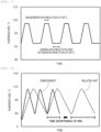
- Fig. 7 is a diagram illustrating an example of a temperature control cycle in nucleic acid amplification according to a PCR method.
- a degeneration reaction for separating two DNA chains to one chain an annealing reaction for connecting one DNA chain with a primer, and an expansion reaction for duplicating two DNA chains are performed.
- a degeneration reaction for separating two DNA chains to one chain an annealing reaction for connecting one DNA chain with a primer, and an expansion reaction for duplicating two DNA chains are performed.
- the temperature control block 2 comes into direct contact with the electrode 301A of the thermoelectric conversion unit 3, the temperature control block 2 is required to be formed of an electrically insulating material. To adjust a temperature of the reaction liquid 102 rapidly and accurately, a material of the temperature control block 2 preferably has small specific heat and large thermal conductivity.
- thermoelectric conversion unit 3 When a temperature control cycle of the PCR method illustrated in Fig. 7 is performed by the thermoelectric conversion unit 3, a difference in temperature between both surfaces of the thermoelectric conversion unit 3 (a surface coming into contact with the temperature control block 2 and a surface coming into contact with the insulating substrate 4) considerably varies and members (the temperature control block 2 and the insulating substrate 4) sandwiching the thermoelectric conversion unit 3 are thermally expanded and contracted repeatedly. Due to the thermal deformation, stress is repeatedly applied to junctions between the electrode 301 and the semiconductor elements 302 and 303, and thus cracks occur in the solder 6, which is a cause to shorten a lifespan of the thermal cycler 20. Accordingly, the material of the temperature control block 2 preferably has a small coefficient of thermal expansion and small Young's modulus.
- the temperature control block 2 is preferably formed of an insulating material selected from a group consisting of compounds of carbon, high thermal conductive ceramics, and cermet.
- an insulating material selected from a group consisting of compounds of carbon, high thermal conductive ceramics, and cermet.
- aluminum nitride and boron nitride can be exemplified as strong candidates.
- Table 1 shows examples of thermophysical properties of alumina Al 2 O 3 , aluminum alloy A5052, and aluminum nitride AlN.
- Alumina Al 2 O 3 is a representative material of the insulating substrate 4A, and the insulating substrate 4B in the thermal cycler 30 according to the related art.
- Alumina alloy A5052 is used as a representative material of the temperature control block 2 in the thermal cycler 30 according to the related art.
- Aluminum nitride AlN is ceramics with electric insulation.
- the temperature control block 2 included in the thermal cycler 20 according to the embodiment is preferably formed of aluminum nitride.
- the temperature control block 2 was assumed to have a shape including a cylindrical member in the middle of the flat plate.
- a size of the flat plate has a width, a depth, and a thickness of 15 mm ⁇ 15 mm ⁇ 1.2 mm.
- the recessed portion 1 where the reaction vessel 101 was installed was modeled in a cylindrical shape with an inner diameter of 5 mm, an outer diameter of 6.4 mm, and a height of 7.8 mm.
- a material of the temperature control block 2 was aluminum nitride. In the temperature control block 2, an influence of the cylindrical member on thermal strain was neglected.
- the insulating substrate 4A was a flat plate with a size of a width, a depth, and a thickness of 15 mm ⁇ 15 mm ⁇ 1.0 mm and the material was alumina.
- Table 2 shows calculation results of external force necessary to make thermal strain zero when a temperature is increased by 1°C in the temperature control block 2 of the thermal cycler 20 according to the embodiment and the insulating substrate 4A of the thermal cycler 30 according to the related art under the foregoing conditions.
- external force external force per unit temperature change
- external force necessary to make thermal strain zero when the temperature of the temperature control block 2 is increased by 1°C is 26.5 N/K.
- external force necessary to make thermal strain zero when the temperature of the insulating substrate 4A is increased by 1°C is 38.9 N/K.
- the external force necessary to make thermal strain zero when the temperature of the temperature control block 2 is increased by 1°C is 68% of the external force necessary in the thermal cycler 30 according to the related art, and is less than the external force in the thermal cycler 30 according to the related art. Accordingly, in the thermal cycler 20 according to the embodiment, it is possible to obtain the advantage of reducing a load applied to the junctions of the electrode 301 and the semiconductor elements 302 and 303.
- thermoelectric conversion unit 3 an object heated or cooled by the thermoelectric conversion unit 3 is the temperature control block 2.
- thermoelectric conversion unit 3 an object heated or cooled by the thermoelectric conversion unit 3 is the temperature control block 2 and the insulating substrate 4A.
- the temperature control block 2 was assumed to have a shape including, for example, a cylindrical member in the middle of the flat plate in the thermal cycler 20 according to the embodiment and the thermal cycler 30 according to the related art.
- a size of the flat plate has a width, a depth, and a thickness of 15 mm ⁇ 15 mm ⁇ 1.2 mm.
- the recessed portion 1 where the reaction vessel 101 was installed was modeled in a cylindrical shape with an inner diameter of 5 mm, an outer diameter of 6.4 mm, and a height of 7.8 mm.
- a material of the temperature control block 2 was aluminum nitride.
- the insulating substrate 4A was a flat plate with a size of a width, a depth, and a thickness of 15 mm ⁇ 15 mm ⁇ 1.0 mm, the material of the temperature control block 2 was A5052, and the material of the insulating substrate 4A was alumina.
- Table 3 shows calculation results of a heat capacity of the temperature control block 2 of the thermal cycler 20 according to the embodiment and a heat capacity of the temperature control block 2 and the insulating substrate 4A of the thermal cycler 30 according to the related art under the foregoing conditions.
- a heat capacity of an object (the temperature control block 2) heated or cooled by the thermoelectric conversion unit 3 is 0.87 J/K.
- a heat capacity of an object (the temperature control block 2 and the insulating substrate 4A) heated or cooled by the thermoelectric conversion unit 3 is 1.63 J/K.
- the heat capacity of an object heated or cooled by the thermoelectric conversion unit 3 is about 53% of the heat capacity in the thermal cycler 30 according to the related art and is less than the heat capacity of the thermal cycler 30 according to the related art. Therefore, the thermal cycler 20 according to the embodiment can heat or cool the reaction liquid 102 more rapidly than the thermal cycler 30 according to the related art.
- an overall thermal resistance from the thermoelectric conversion unit 3 to the tip end of the temperature control block 2 was calculated and obtained in the thermal cycler 20 according to the embodiment and the thermal cycler 30 according to the related art.
- An overall thermal resistance in the thermal cycler 20 according to the embodiment is a thermal resistance of the temperature control block 2.
- An overall thermal resistance in the thermal cycler 30 according to the related art is a sum of the thermal resistance of the temperature control block 2, the thermal resistance of the insulating substrate 4A, and the contact thermal resistance on the interface between the temperature control block 2 and the insulating substrate 4A.
- the thermal resistance of the temperature control block 2 in the thermal cycler 20 according to the embodiment is a sum of R1 and R2 in Fig. 6 .
- the thermal resistance of the temperature control block 2 in the thermal cycler 30 according to the related art is a sum of R1, R2, R3, and R4 in Fig. 5 .
- the overall thermal resistance of the thermal cycler 20 according to the embodiment and the overall thermal resistance of the thermal cycler 30 according to the related art were calculated under the same conditions as the conditions when the heat capacities shown in Table 3 were obtained.
- the thermal interface material is interposed between the temperature control block 2 and the insulating substrate 4A, and thus the contact thermal resistance was assumed to be 10 -6 (m 2 ⁇ K)/W.
- Table 4 shows calculation results of the thermal resistance of the temperature control block 2 in the thermal cycler 20 according to the embodiment, the thermal resistance of the temperature control block 2 in the thermal cycler 30 according to the related art, the contact thermal resistance on the interface between the temperature control block 2 and the insulating substrate 4A, and the thermal resistance of the insulating substrate 4A under the foregoing conditions.
- Table 4 shows overall thermal resistances in the thermal cycler 20 according to the embodiment and the thermal cycler 30 according to the related art. In the thermal cycler 20 according to the embodiment, the overall thermal resistance is 4.2 K/W. In the thermal cycler 30 according to the related art, the overall thermal resistance is 4.6 K/W.
- the overall thermal resistance from the thermoelectric conversion unit 3 to the tip end of the temperature control block 2 is about 90% of the overall thermal resistance in the thermal cycler 30 according to the related art and is less than the overall thermal resistance in the thermal cycler 30 according to the related art. Therefore, the thermal cycler 20 according to the embodiment can heat or cool the reaction liquid 102 efficiently and rapidly.
- Thermal cycler according to related art Thermal cycler according to embodiment Thermal resistance of temperature control block 2 K/W 4.5 4.2
- Fig. 8 is a diagram illustrating comparison between numerical value calculation results obtained by comparing heating or cooling speeds between the thermal cycler 20 according to the embodiment of the invention and the thermal cycler 30 according to the related art.
- the horizontal axis of the drawing represents time and the vertical axis represents temperature of the temperature control block 2.
- a solid line indicates a result of the thermal cycler 20 according to the embodiment of the invention and a dotted line indicates a result of the thermal cycler 30 according to the related art.
- an initial temperature of the temperature control block 2 was set to 21°C and a heating and cooling simulation in which a course from an increase in the temperature until about 105°C to a decrease until about 40°C was repeated three times was performed.
- the results of the third heating and cooling course were compared, it was understood that it is possible to obtain the advantage of shortening a required time in the thermal cycler 20 according to the embodiment by 490 of a required time in the thermal cycler 30 according to the related art.
- Fig. 9 is a sectional view illustrating an outline of a configuration in which the temperature control block 2 is fixed in the thermal cycler 30 according to the related art and corresponding to the line B-B of Fig. 1 .
- the insulating substrate 4A, the thermoelectric conversion unit 3, and the insulating substrate 4B configure a thermoelectric conversion module.
- the temperature control block 2, the thermoelectric conversion module, and the heat radiating unit 5 are each independent components. It is necessary to fix two temperature control block 2 and thermoelectric conversion module when fixed to the heat radiating unit 5.
- the thermoelectric conversion module is fixed to the heat radiating unit 5 by a fixing member 11 with the thermoelectric conversion module interposed between the temperature control block 2 and the heat radiating unit 5.
- a fixing member 11 With the thermoelectric conversion module interposed between the temperature control block 2 and the heat radiating unit 5.
- contact thermal resistances between the temperature control block 2 and the insulating substrate 4A and between the insulating substrate 4B and the heat radiating unit 5 are reduced. That is, the fixing member 11 contacts with the temperature control block 2 and the heat radiating unit 5.
- a temperature of the temperature control block 2 is high and a temperature of the heat radiating unit 5 is low. Therefore, a heat conduction and transfer path is formed from the temperature control block 2 to the heat radiating unit 5 via the fixing member 11.
- a heat loss occurs in the heat conduction and transfer path between the temperature control block 2 and the heat radiating unit 5 due to the fixing member 11.
- the heat loss obstructs efficient and rapid heating and cooling of the reaction liquid 102.
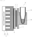
- Fig. 10 is a sectional view illustrating an outline of a configuration in which the temperature control block 2 is fixed in the thermal cycler 20 according to the embodiment of the invention and corresponding to the line B-B of Fig. 1 .
- the temperature control block 2, the thermoelectric conversion unit 3, and the insulating substrate 4 configure a temperature control module.
- the temperature control module is a component independent from the heat radiating unit 5.
- the insulating substrate 4 of the temperature control module is fastened and fixed to the heat radiating member 501 of the heat radiating unit 5 by, for example, the fixing member 11 and a fixing screw 12.
- the fixing member 11 contacts with the insulating substrate 4, the heat radiating unit 5, and the fixing screw 12 for fastening.
- the fixing member 11 does not fasten the temperature control block 2 and the heat radiating unit 5. That is, the fixing member 11 does not contact with the temperature control block 2 and does not form the heat conduction and transfer path via the fixing member 11 between the temperature control block 2 and the heat radiating unit 5. Since the temperature control block 2 and the thermoelectric conversion unit 3 are configured to be joined, it is not necessary to perform the fixing by the fixing member 11 from the temperature control block 2 as in the thermal cycler 30 according to the related art.
- thermo cycler 20 a heat loss caused in the heat conduction and transfer path between the temperature control block 2 and the heat radiating unit 5 by the fixing member 11 does not occur, and thus the reaction liquid 102 can be heated or cooled efficiently and rapidly.
- Fig. 11 is a sectional view illustrating an outline of another configuration of the thermal cycler 20 according to the embodiment of the invention.
- constituent elements are arranged side by side in the horizontal direction.
- a direction of contact (the upper and lower directions of Fig. 1 ) with the thermoelectric conversion unit 3 of the temperature control block 2 is a depression direction of the recessed portion 1 of the temperature control block 2. That is, the direction is the same as the installation direction of the reaction vessel 101, and is a vertical direction.
- a direction of contact (the right and left directions of Fig. 5 ) with the thermoelectric conversion unit 3 of the temperature control block 2 is a depression direction (the upper and lower directions of Fig. 5 ) of the recessed portion 1 of the temperature control block 2. That is, the direction is different from the installation direction (vertical direction) of the reaction vessel 101, and is a horizontal direction.
- the temperature control block 2 the thermoelectric conversion unit 3, the insulating substrate 4, and the heat radiating unit 5 may be arranged side by side in the vertical direction, as illustrated in Fig. 1 or may be arranged side by side in the horizontal direction, as illustrated in Fig. 11 .
- the upward recessed portion 1 where depression extends in the vertical direction is installed so that the reaction vessel 101 is installed.
- Fig. 12 is a sectional view illustrating an outline of a configuration in which the temperature sensor 8 is fixed in the thermal cycler 20 according to the embodiment of the invention. Since a value of a current or a voltage applied to the thermoelectric conversion unit 3 is adjusted according to an output of the temperature sensor 8, it is necessary to measure a temperature of the temperature control block 2.
- the temperature sensor 8 is fixed in a screw hole or the like provided in the temperature control block 2 by a fixing screw, or the temperature sensor 8 is inserted and fixed into a small hole provided in the temperature control block 2.
- the thermal cycler 20 according to the embodiment when the temperature control block 2 is formed of ceramics such as aluminum nitride, it may be difficult to process the screw hole or the small hole.
- a metal plated layer 304C is applied to the opposite surface to the thermoelectric conversion unit 3 of the temperature control block 2 and the temperature sensor 8 is mounted on the metal plated layer 304C.
- FIG. 13 is a sectional view illustrating an outline of another configuration in which the temperature sensor 8 is fixed in the thermal cycler 20 according to the embodiment of the invention.
- the number of times a metal plated process is processed using the installation position of the temperature sensor 8 as the surface of the temperature control block 2 on the side of the thermoelectric conversion unit 3 may be reduced.
- the temperature sensor 8 can be fixed to the temperature control block 2 formed of ceramics such as aluminum nitride for which it is difficult to process the screw hole or the small hole.
- thermocouple for example, a thermocouple, a thermistor, a platinum resistance temperature detector, or the like is used.
- Fig. 14 is a sectional view illustrating an outline of a configuration of the thermal cycler 20 that simultaneously heats or cools the plurality of reaction vessels 101 according to the embodiment of the invention.
- the temperature control block 2 includes the plurality of recessed portions 1 where the reaction vessels 101 can be installed and simultaneously heat or cool the reaction liquids 102 stored in the plurality of reaction vessels 101 to amplify nucleic acids efficiently.
- a rack mounting unit 610 a transport mechanism 620, a liquid dispensing mechanism 630, a lid unit 640, a stirring unit 650, a control device 690, the thermal cycler 20, and a measurement unit 665 are included.
- a liquid preparation unit that generates the reaction liquids 102 includes a rack mounting unit 110, a transport mechanism 120, a liquid dispensing mechanism 130, and a lid unit 140.
- the rack mounting unit 610 a sample, a reagent, a dispensing tip, and the reaction vessel 101 used for inspection are disposed.
- the rack mounting unit 610 is provided at a predetermined position on a work table 601 of the genetic inspection apparatus 600.
- a sample vessel rack 612, a reagent vessel rack 614, a reaction vessel rack 616, and a nozzle tip rack 618 are each mounted.
- sample vessel rack 612 a plurality of sample vessels 613 that accommodate samples including nucleic acids which are amplification processing targets are stored.
- reagent vessel rack 614 the plurality of reagent vessels 615 accommodating reagents added to the samples are stored.
- reaction vessel rack 616 the plurality of unused empty reaction vessels 101 used to mix the samples and the reagents are stored.
- nozzle tip rack 618 a plurality of unused nozzle tips 619 used to dispense the samples and the reagents are stored.
- the transport mechanism 620 is a mechanism that moves each spot in the genetic inspection apparatus 600 while holding the reaction vessel 101 or the like, includes an X axis direction guide 621, an X axis direction mover 622, a Y axis direction guide 623, and a Y axis direction mover 624, and is configured to move the Y axis direction mover 624 on the work table 601 based on a control signal so that the Y axis direction mover 624 can be disposed at a predetermined position on the work table.
- the X axis direction guide 621 is a guide that extends in the X axis direction in Fig. 15 to be disposed on the work table 601 of the genetic inspection apparatus 600.
- the X axis direction mover 622 is a mover that is provided to be movable on the X axis direction guide 621.
- the Y axis direction guide 623 is a guide that is attached and integrated with the X axis direction mover 622 and extends in the Y axis direction in Fig. 15 to be disposed.
- the Y axis direction mover 624 is a mover that is provided to be movable on the Y axis direction guide 623.
- the Y axis direction mover 624 includes a barcode reader 625, a gripper unit 626, and a dispensing unit 627 which are moved integrally with the Y axis direction mover 624 on the work table 601 to be disposed at a predetermined position.
- the barcode reader 625 reads identification information attached to each of the sample vessel 613, the reagent vessel 615, and the reaction vessel 101 to acquire the identification information.
- the gripper unit 626 grips or releases the reaction vessel 101 in response to an operation of a gripper based on a control signal and transports the reaction vessel 101 in association with movement of the Y axis direction mover 624 between the units of the apparatus on the work table 601.
- the dispensing unit 627 is configured so that the nozzle tip 619 can be attached and detached, the nozzle tip 619 is mounted from the nozzle tip rack 618 based on a control signal, the nozzle tip 619 is immersed into a sample inside the sample vessel 613 or a reagent inside the reagent vessel 615, and the sample or the reagent is sucked and picked into the nozzle tip 619.
- the dispensing unit 627 ejects and dispenses the sample or the reagent stored inside the nozzle tip 619 into the reaction vessel 101 based on a control signal.
- the dispensing unit 627 is a main unit of the liquid dispensing mechanism 630 which is a mechanism dispensing the sample and the reagent using the dispensing tip inside one selected reaction vessel 101 and preparing the reaction liquid.
- a reaction liquid preparation position 670 is formed at which the unused reaction vessel 101 extracted from the reaction vessel rack 616 to prepare the reaction liquid is placed on the work table 601 between the rack mounting unit 610 and the thermal cycler 20.
- a vessel mounting unit 672 holding the reaction vessel 101 is provided.
- the dispensing unit 627 is used to dispense the sample and the reagent from the sample vessel 613 and the reagent vessel 615 with respect to the unused reaction vessel 101 moved to the reaction liquid preparation position 670 from the reaction vessel rack 616 using the gripper unit 626, and to prepare the reaction liquid in which the sample and the reagent are mixed inside the reaction vessel 101.
- the plurality of vessel mounting unit 672 are included. Accordingly, for example, the same sample and the same reagent can be dispensed to the plurality of reaction vessels 101 together and batch processing can be performed en bloc to prepare the plurality of reaction liquids.
- the lid unit 640 is a mechanism that serves as a lid of the reaction vessel 101 that accommodates the reaction liquid, and is a lid for an opening of the reaction vessel 101 that accommodates the reaction liquid and is moved from the reaction liquid preparation position 670 using the gripper unit 626.
- the lid unit 640 prevents evaporation of the reaction liquid, intrusion of foreign matters from the outside, or the like.
- the stirring unit 650 is a mechanism that uniformly mixes the sample and the reagent of the reaction liquid accommodated in the reaction vessel 101, stirs the reaction liquid accommodated in the hermetic reaction vessel 101 moved from the lid unit 640 using the gripper unit 626, and mixes the sample and the reagent.
- the used nozzle tip 619 which is mounted on the dispensing unit 627 and is used to dispense the sample or the reagent, or a discarding box 680 for discarding the inspected reaction vessel 101 subjected to the nucleic acid amplification process by the thermal cycler 20 is provided on the work table 601 between the reaction liquid reparation position 670 and the rack mounting unit 610.
- the stirred reaction vessel 101 is mounted on the thermal cycler 20 and the nucleic acids of the reaction liquid are amplified according to a predetermined protocol.
- the measurement unit 665 is disposed above the reaction vessel 101 holding the reaction liquid and measures density of the nucleic acid by measuring a fluorescent property of the reaction liquid of which a temperature has been adjusted according to the predetermined protocol by the thermal cycler 20.
- the measurement unit 665 includes an excitation light source that irradiates a vessel portion of an exposed bottom side of the facing reaction vessel 101 with excitation light and a detection element that detects fluorescence from the reaction liquid based on the irradiation of the excitation light.
- the excitation light source for example, a light emitting diode (LED), a semiconductor laser, a xenon lamp, a halogen lamp, or the like is used.
- the detection element a photodiode, a photo-multiplier, a CCD, or the like is used.
- the measurement unit 665 measures a quantity of a base sequence of an amplification target marked with fluorescence by the reagent in the reaction liquid by causing the detection element to detect and measure fluorescence generated from the reaction liquid through irradiation of the excitation light from the excitation light source.
- each unit of the apparatus including the thermal cycler 20 of the genetic inspection apparatus 600 that has such a configuration is controlled by the control device 690 including an input device 692 such as a keyboard or a mouse, and a display device 693 such as a liquid crystal monitor.
- the control device 690 controls each unit of the above-described apparatus including the thermal cycler 20 of the genetic inspection apparatus 600 and performs a nucleic acid inspection process including a reaction liquid preparation process and a nucleic acid amplification process using various types of software stored in advance in a storage unit 691 based on a protocol set by the input device 692.
- the control device 690 stores an operation status or the like of each unit of the apparatus in the nucleic acid inspection process in the storage unit 691, stores an analysis result such as a fluorescence detection result obtained by the thermal cycler 20 in the storage unit 691, and displays the analysis result on the display device 693.
- the control device 690 is configured to control temperatures of the plurality of thermal cyclers 20 independently in parallel.
- the reaction liquid preparation process is a process of preparing a reaction liquid in which the sample and the reagent are dispensed in the reaction vessel 101 in the nucleic acid inspection process performed by the control device 690 of the genetic inspection apparatus 600.
- the nucleic acid amplification process is a process of causing the thermal cycler 20 to adjust a temperature of the reaction liquid prepared in the reaction vessel 101 through the reaction liquid preparation process by a protocol according to a type of base sequence of an amplification target and amplifying the nucleic acid of the base sequence while checking the nucleic acid through fluorescence measurement of the reaction liquid by the measurement unit 665.
- the control device 690 first initializes various work areas used for the reaction liquid preparation process and provided in the storage unit 691 when the reaction liquid preparation process starts.
- control device 690 When the initialization related to the reaction liquid preparation process ends, the control device 690 performs a process of reading sample vessel rack information and reagent vessel rack information set by the input device 692 or execution content information of the nucleic acid inspection.
- the control device 690 selects and extracts one or a plurality of individual nucleic acid processes to perform the reaction liquid preparation process at present time based on an order set in advance in one or a plurality of individual nucleic acid inspection processes included in the execution content information of the nucleic acid inspection.
- the control device 690 prepares the reaction liquid by controlling an operation of the liquid dispensing mechanism 630 based on reaction liquid preparation processing information of the selected and extracted individual nucleic acid process with regard to the unprocessed reaction vessel 101 transported in advance from the reaction vessel rack 616 and mounted on the vessel mounting unit 672 of the reaction liquid preparation position 670.
- the thermal cycler 20 and the genetic inspection apparatus 600 according to the embodiment can heat or cool the reaction liquid rapidly and efficiently, as described above. It is possible to provide a thermal cycler that has a long device lifespan, and a genetic inspection apparatus including the thermal cycler.
- the invention is not limited to the foregoing embodiment and can be modified in various forms.
- the foregoing embodiment has been described in detail to easily understand the invention.
- the invention is not limited to aspects in which all the described configurations are not necessarily included.
- Some of configurations of a certain embodiment can replaced with configurations of another embodiment.
- configurations of another embodiment can also be added.
- a configuration can be deleted or another configuration may be added or replaced.
Landscapes
- Health & Medical Sciences (AREA)
- Chemical & Material Sciences (AREA)
- Life Sciences & Earth Sciences (AREA)
- Biochemistry (AREA)
- General Health & Medical Sciences (AREA)
- Molecular Biology (AREA)
- Clinical Laboratory Science (AREA)
- Chemical Kinetics & Catalysis (AREA)
- Apparatus Associated With Microorganisms And Enzymes (AREA)
- Measuring Or Testing Involving Enzymes Or Micro-Organisms (AREA)
Abstract
Description
- The present invention relates to a thermal cycler, and more particularly, to a thermal cycler used for a genetic inspection apparatus.
- Some genetic inspection apparatuses include nucleic acid amplification devices using a polymerase chain reaction (PCR) method. The nucleic acid amplification devices include thermal cyclers to adjust temperatures of reaction liquids in which reagents and samples originated from living bodies extracted from blood, saliva, urine, or the like are mixed.
- In the PCR method, a cycle formed by thermal denaturation, annealing, and expansion steps of a nucleic acid is repeated dozens of times to amplify one molecule to millions of molecules. The nucleic acid amplification process is implemented by repeating a temperature adjustment cycle (hereinafter referred to as a "temperature control cycle") at which a temperature of a reaction liquid including a nucleic acid is controlled in a range of, for example, about 65°C to 95°C. A genetic inspection apparatus is required to have performance capable of accelerating temperature adjustment and shortening a time required to amplify nucleic acids to shorten an inspection time or increasing the number of processes within a predetermined time. Therefore, a technology for heating and cooling a temperature of the reaction liquid at a high speed is required in a thermal cycler used for a genetic inspection apparatus.
- A time required to change a temperature of an object is characterized by a heat transfer amount transferred to the object which changes temperature and a heat capacity and thermal conductivity of the object. A thermal cycler used for a general genetic inspection apparatus includes a temperature adjustment block (a temperature control block) in which a reaction vessel where a reaction liquid is input is installed and a thermoelectric conversion module configured by sandwiching an electric circuit (a thermoelectric conversion unit) including a thermoelectric semiconductor and an electrode between insulating substrates. In such a thermal cycler, a temperature of the temperature control block storing a reaction liquid is heated or cooled by adjusting heat generation, heat absorption or joule heating obtained through a thermoelectric conversion action by changing a current or a voltage applied to a thermoelectric conversion module. To accelerate a temperature control cycle, it is necessary to increase a value of a heat transfer amount of heating or cooling and decrease a heat capacity or thermal resistance of an object which changes a temperature.
- An example of a thermal cycler according to the related art is disclosed in
PTL 1. A supporter for many samples disclosed inPTL 1 includes a block of a unitary structure, a series of sample wells in the block, and a series of hollow portions in the block between the sample wells. A mass of the block is reduced by the hollow portions, a heat capacity is decreased, and a change in temperature is transferred to the samples fast. - PTL 1:
JP2009-543064T - As described above, to accelerate a temperature control cycle, in thermal cyclers, it is conceivable that a heat transfer amount of heating or cooling is increased and a heat capacity of an object which changes a temperature is decreased. In thermal cyclers according to the related art, a heat capacity of a temperature control block is dominant in the heat capacity of the object which changes a temperature. In thermal cyclers according to the related art, thermoelectric conversion modules of mass-market products configured with insulating substrates using alumina as a material are used in many cases. Thus, as a reduction of the heat capacity of the temperature control block is in progress, a ratio of the heat capacity caused from the insulating substrates configuring the thermoelectric conversion module has increased considerably in the heat capacity of the object which changes a temperature. Deterioration in a heat transfer amount is unavoidable due to thermal resistance of the insulating substrate and a thermal interface material such as a thermal conductive grease interposed between the temperature control block and the insulating substrate. Therefore, considering a reduction in the heat capacity of the temperature control block, there are needs for a thermal cycler that can heat or cool a reaction liquid rapidly and efficiently. In the thermoelectric conversion module in the thermal cycler according to the related art, repeated thermal strain occurring in a solder junction where a large temperature difference occurs between both surfaces of the thermoelectric conversion module while a temperature control cycle is performed multiple times is one of the reasons to deteriorate a lifespan or performance of apparatuses.
- An object of the present invention is to provide a thermal cycler which can heat or cool a reaction liquid rapidly and efficiently and has a long lifespan and provide a genetic inspection apparatus including the thermal cycler.
- According to an aspect of the present invention, a thermal cycler includes: a temperature adjustment block configured such that a reaction vessel storing a reaction liquid in which a sample and a reagent are mixed is installable; a thermoelectric conversion unit capable of performing heating and cooling; a temperature sensor configured to measure a temperature of the temperature adjustment block; an insulating substrate configured such that one surface contacts with the thermoelectric conversion unit; and a heat radiating unit provided on the other surface of the insulating substrate and configured to discharge heat of the thermoelectric conversion unit to the outside. A current or a voltage supplied to the thermoelectric conversion unit is controlled based on the temperature of the temperature adjustment block measured by the temperature sensor to heat and cool the temperature adjustment block. The thermoelectric conversion unit is sandwiched between the temperature adjustment block and the insulating substrate, and the temperature adjustment block is formed of an electrically insulating material and is installed to be in contact with the thermoelectric conversion unit.
- According to another aspect of the present invention, a genetic inspection apparatus includes the thermal cycler and a measurement unit configured to measure a fluorescent property of a reagent solution of which a temperature is adjusted by the thermal cycler.
- According to the present invention, it is possible to provide a thermal cycler which can heat or cool a reaction liquid rapidly and efficiently and has a long lifespan and a genetic inspection apparatus which includes the thermal cycler and can perform inspection in a short time.
-
- [
Fig. 1] Fig. 1 is a perspective view illustrating an outline of a configuration of a thermal cycler according to an embodiment of the invention. - [
Fig. 2] Fig. 2 is a sectional view illustrating the outline of the configuration of the thermal cycler according to the embodiment of the invention. - [
Fig. 3] Fig. 3 is a sectional view illustrating an outline of a configuration of a thermoelectric conversion unit according to the embodiment of the invention. - [
Fig. 4] Fig. 4 is a sectional view illustrating an outline of a configuration of a thermal cycler according to the related art. - [
Fig. 5] Fig. 5 is a schematic view illustrating an outline of a temperature distribution on a heat transfer path from a tip end of a temperature control block to a heat radiating unit in the thermal cycler according to the related art. - [
Fig. 6] Fig. 6 is a schematic view illustrating an outline of a temperature distribution on a heat transfer path from a tip end of a temperature control block to a heat radiating unit in the thermal cycler according to the embodiment of the invention. - [
Fig. 7] Fig. 7 is a diagram illustrating an example of a temperature control cycle of a PCR method. - [
Fig. 8] Fig. 8 is a diagram illustrating comparison between numerical value calculation results obtained by comparing heating or cooling speeds between the thermal cycler according to the embodiment of the invention and the thermal cycler according to the related art. - [
Fig. 9] Fig. 9 is a sectional view illustrating an outline of a configuration in which the temperature control block is fixed in the thermal cycler according to the related art. - [
Fig. 10] Fig. 10 is a sectional view illustrating an outline of a configuration in which the temperature control block is fixed in the thermal cycler according to the embodiment of the invention. - [
Fig. 11] Fig. 11 is a sectional view illustrating an outline of another configuration of the thermal cycler according to the embodiment of the invention. - [
Fig. 12] Fig. 12 is a sectional view illustrating an outline of a configuration in which a temperature sensor is fixed in the thermal cycler according to the embodiment of the invention. - [
Fig. 13] Fig. 13 is a sectional view illustrating an outline of another configuration in which the temperature sensor is fixed in the thermal cycler according to the embodiment of the invention. - [
Fig. 14] Fig. 14 is a sectional view illustrating an outline of a configuration of the thermal cycler that simultaneously heats or cools a plurality of reaction vessels according to the embodiment of the invention. - [
Fig. 15] Fig. 15 is a diagram illustrating a configuration of a genetic inspection apparatus according to the embodiment of the invention. - A thermal cycler according to the present invention can heat or cool a temperature of a reaction liquid rapidly by reducing a heat capacity caused in an insulating substrate configuring a thermoelectric conversion module included in a thermal cycler according to the related art and reducing thermal resistance caused by a thermal interface material such as a thermal conductive grease interposed between a temperature control block and the insulating substrate. A genetic inspection apparatus according to the invention includes the thermal cycler according to the invention.
- Hereinafter, a thermal cycler and a genetic inspection apparatus according to an embodiment of the invention will be described with reference to the drawings. In the drawings used in the present specification, the same reference numerals are given to the same or corresponding constituent elements and repeated description of the constituent elements will be omitted in some cases.
- A thermal cycler according to the embodiment will be described.
-
Fig. 1 is a perspective view illustrating an outline of a configuration of athermal cycler 20 according to the embodiment of the invention.Fig. 2 is a sectional view illustrating the outline of the configuration of thethermal cycler 20 according to the embodiment of the invention and corresponding to the line A-A ofFig. 1 . Thethermal cycler 20 includes a temperature adjustment block 2 (hereinafter referred to as a "temperature control block 2"), athermoelectric conversion unit 3, aninsulating substrate 4, and aheat radiating unit 5. - In the
temperature adjustment block 2, areaction vessel 101 that contains areaction liquid 102 can be installed. Thetemperature control block 2 may be configured to install thereaction vessel 101 in therecessed portion 1 or may be configured to place thereaction vessel 101 on the surface of thetemperature adjustment block 2. In the embodiment, thetemperature control block 2 includes therecessed portion 1 where thereaction vessel 101 is installed. Thetemperature control block 2 is installed to be in contact with thethermoelectric conversion unit 3. Thereaction liquid 102 includes a reagent and a sample including a nucleic acid. - The
thermoelectric conversion unit 3 is a temperature adjustment device capable of heating one surface and cooling the other surface by a thermoelectric conversion action and switches between heating and cooling surfaces according to a current flowing direction. Accordingly, thereaction liquid 102 contained in thereaction vessel 101 installed in thetemperature control block 2 is heated and cooled.Fig. 3 is a sectional view illustrating an outline of a configuration of thethermoelectric conversion unit 3 in thethermal cycler 20 according to the embodiment of the invention and corresponding to the line B-B ofFig. 1 . Thethermoelectric conversion unit 3 includes atleast electrodes type semiconductor element 302, and an N-type semiconductor element 303. A pair of P-type semiconductor element 302 and N-type semiconductor element 303 are electrically connected in series by the electrodes 301. The P-type semiconductor element 302 and the N-type semiconductor element 303 are joined to the electrodes 301 by asolder 6.Lead wires Fig. 1 are connected to the electrodes 301. Thethermoelectric conversion unit 3 heats one surface and cools the other surface by applying currents from thelead wires thermoelectric conversion unit 3 can switch between heating and cooling of thereaction liquid 102 according to a direction of the applied current. A value of a current or a voltage applied to thethermoelectric conversion unit 3 is adjusted according to an output of thetemperature sensor 8 and thetemperature control block 2 is controlled according to a designated temperature. - As a specific structure, a metal plated
layer 304A is applied to the surface of thetemperature control block 2 and theelectrode 301A is mounted on the metal platedlayer 304A. On the other hand, a metal platedlayer 304B is applied to the surface of the insulatingsubstrate 4 and anelectrode 301B is mounted on the metal platedlayer 304B. By joining one ends of the N-type semiconductor element 303 and the P-type semiconductor element 302 to theelectrode 301A and joining other ends to theelectrode 301B, thethermoelectric conversion unit 3 in which the N-type semiconductor element 303 and the P-type semiconductor element 302 are joined alternately and in series is sandwiched between thetemperature control block 2 and the insulatingsubstrate 4. - The insulating
substrate 4 is installed between thethermoelectric conversion unit 3 and theheat radiating unit 5 to be in contact with thethermoelectric conversion unit 3 and theheat radiating unit 5. One surface of the insulatingsubstrate 4 comes into contact with thethermoelectric conversion unit 3 and the other surface thereof comes into contact with theheat radiating unit 5 to electrically insulate thethermoelectric conversion unit 3 from theheat radiating unit 5 such that thermoelectric conversion can work properly. In many cases, athermal interface material 10 such as a thermal conductive grease is interposed between the insulatingsubstrate 4 and theheat radiating unit 5 to reduce contact thermal resistance. - The
heat radiating unit 5 is provided on the other surface of the insulatingsubstrate 4. When thetemperature control block 2 is cooled and a temperature of theheat radiating unit 5 becomes higher than the periphery of theheat radiating unit 5 by applying a current or a voltage to thethermoelectric conversion unit 3, heat from thethermoelectric conversion unit 3 is discharged to the outside. When thetemperature control block 2 is heated and the temperature of theheat radiating unit 5 becomes lower than the periphery of theheat radiating unit 5 by reversing the current or the voltage applied to thethermoelectric conversion unit 3, heat is absorbed from the outside. For example, theheat radiating unit 5 includes a heat radiating member 501 (for example, a fin) and ablower 502 and discharges heat from thethermoelectric conversion unit 3 to the outside by conductive heat transfer with the air. Theheat radiating unit 5 may have a configuration in which a liquid flows to transfer heat and convey the heat from thethermoelectric conversion unit 3 to the outside. - In the
thermal cycler 20 according to the embodiment, thetemperature control block 2, thethermoelectric conversion unit 3, and the insulatingsubstrate 4 configure one temperature adjustment module (hereinafter referred to as "temperature control module"). That is, thethermal cycler 20 according to the embodiment includes the temperature control module and theheat radiating unit 5. In the temperature control module, thethermoelectric conversion unit 3 is sandwiched between thetemperature control block 2 and the insulatingsubstrate 4, and thetemperature control block 2 comes into contact with the electrode 301 of thethermoelectric conversion unit 3. - Here, a thermal cycler according to the related art will be described. In the thermal cycler according to the related art, description of a configuration common with the thermal cycler 20 (
Figs. 1 and2 ) according to the embodiment will be omitted. -
Fig. 4 is a sectional view illustrating an outline of a configuration of athermal cycler 30 according to the related art. Thethermal cycler 30 includes thetemperature control block 2, thethermoelectric conversion unit 3, and two insulatingsubstrates heat radiating unit 5. - The
thermoelectric conversion unit 3 has a structure in which the P-type semiconductor element 302 and the N-type semiconductor element 303 are joined alternately in series with an electrode interposed therebetween, and is sandwiched between the insulatingsubstrates - The insulating
substrate 4A is installed between thetemperature control block 2 and thethermoelectric conversion unit 3 to be in contact with thetemperature control block 2 and thethermoelectric conversion unit 3. On the other hand, the insulatingsubstrate 4B is installed between thethermoelectric conversion unit 3 and theheat radiating unit 5 to be in contact with thethermoelectric conversion unit 3 and theheat radiating unit 5. The insulatingsubstrate 4A electrically insulates thetemperature control block 2 from thethermoelectric conversion unit 3 and the insulatingsubstrate 4B electrically insulates thethermoelectric conversion unit 3 from theheat radiating unit 5, and thus thermoelectric conversion works properly. - In the
thermal cycler 30 according to the related art, the insulatingsubstrate 4A, thethermoelectric conversion unit 3, and the insulatingsubstrate 4B configure an integrally formed thermoelectric conversion module 40 (for example, a Peltier module). That is, thethermal cycler 30 according to the related art includes thetemperature control block 2, thethermoelectric conversion module 40, and theheat radiating unit 5. The insulatingsubstrates thermoelectric conversion module 40 are formed in a plate form and sandwich thethermoelectric conversion unit 3 to be a cover of thethermoelectric conversion module 40 that maintains insulation and strength. In thethermal cycler 30 according to the related art, thethermoelectric conversion module 40 of mass-market products formed by the insulatingsubstrates - In the
thermal cycler 30 according to the related art, the insulatingsubstrate 4A of thethermoelectric conversion module 40 comes into contact with thetemperature control block 2 via athermal interface material 10A such as a thermal conductive grease. Because of a structure in which the insulatingsubstrate 4A is between thetemperature control block 2 and thethermoelectric conversion unit 3, both the insulatingsubstrate 4A and thethermal interface material 10A are heated or cooled when thethermoelectric conversion unit 3 heats or cools thetemperature control block 2. Accordingly, a heat capacity can be reduced by reducing a volume of thetemperature control block 2 to heat or cool a temperature of thereaction liquid 102 rapidly, but a heat capacity corresponding to the insulatingsubstrate 4A and thethermal interface material 10A cannot be reduced. Since thetemperature control block 2 and the insulatingsubstrate 4B are individual and independent members, thethermal interface material 10A is generally interposed to reduce contact thermal resistance on an interface between thetemperature control block 2 and the insulatingsubstrate 4A. Alumina with electric insulation is generally used in the insulatingsubstrate 4A, but thermal conductivity of alumina is low as about 33 W/(m·K). Therefore, presence of an interface between the insulatingsubstrate 4A, and thetemperature control block 2 and the insulatingsubstrate 4 obstructs heat transfer on a heat transfer path reaching from thethermoelectric conversion unit 3 to a reaction liquid. - In the thermal cycler 20 (
Figs. 1 ,2 , and3 ) according to the embodiment, thetemperature control block 2, thethermoelectric conversion unit 3, and the insulatingsubstrate 4 configure the temperature control module. Thethermal cycler 20 does not include, as an individual member, the insulatingsubstrate 4A (the insulatingsubstrate 4A between thetemperature control block 2 and the thermoelectric conversion unit 3) included in the thermal cycler 30 (Fig. 4 ) according to the related art, and the interface between thetemperature control block 2 and the insulatingsubstrate 4A does not exist. Therefore, compared to thethermal cycler 30 according to the related art, it is possible to reduce a heat capacity of the insulatingsubstrate 4A and thethermal interface material 10A from a heat capacity of an object of a heated or cooled temperature control module. Since contact thermal resistance originating from an interface between thetemperature control block 2 and the insulatingsubstrate 4A does not occur, a heat transfer amount from thethermoelectric conversion unit 3 to the reaction liquid can be increased. Therefore, in thethermal cycler 20 according to the embodiment, when thethermoelectric conversion unit 3 heats or cools thetemperature control block 2, a change in temperature due to the heat capacity of the insulatingsubstrate 4A and thethermal interface material 10A is not delayed as in thethermal cycler 30 according to the related art, and a heat transfer amount from thethermoelectric conversion unit 3 to the reaction liquid can be increased. Therefore, it is possible to shorten a time required to heat or cool thereaction liquid 102. -
Fig. 5 is a schematic view illustrating an outline of a temperature distribution on a heat transfer path from a tip end of thetemperature control block 2 to theheat radiating unit 5 in thethermal cycler 30 according to the related art. R1 indicates a thermal resistance of the recessedportion 1 of thetemperature control block 2, R2 indicates a thermal resistance of a flat plate of thetemperature control block 2, R3 indicates a contact thermal resistance by thethermal interface material 10A between thetemperature control block 2 and the insulatingsubstrate 4A, R4 indicates a thermal resistance of the insulatingsubstrate 4A, R5 indicates a thermal resistance of thethermoelectric conversion unit 3, R6 indicates a thermal resistance of the insulatingsubstrate 4B, and R7 indicates a thermal resistance of thethermal interface material 10B between the insulatingsubstrate 4B and theheat radiating unit 5. An outline of a temperature distribution at the time of applying of a current or a voltage to thethermoelectric conversion unit 3 and cooling thetemperature control block 2 is illustrated in the drawing. In thethermal cycler 30 according to the related art, a temperature loss caused by the contact thermal resistance R3 of thethermal interface material 10A and the thermal resistance R4 of the insulatingsubstrate 4A occurs from the upper portion of thethermoelectric conversion unit 3 to the bottom surface of thetemperature control block 2. -
Fig. 6 is a schematic view illustrating an outline of a temperature distribution on a heat transfer path from a tip end of thetemperature control block 2 to theheat radiating unit 5 in thethermal cycler 20 according to the embodiment of the invention. In thethermal cycler 20, there is no insulatingsubstrate 4A and no interface between thetemperature control block 2 and the insulatingsubstrate 4A. Therefore, a temperature loss caused by the thermal resistances R3 and R4 does not occur and a heat transfer amount can be increased. Thus, it is possible to shorten a time required for heating or cooling. -
Fig. 7 is a diagram illustrating an example of a temperature control cycle in nucleic acid amplification according to a PCR method. In the example, at a temperature control cycle in which a temperature of thetemperature control block 2 is changed at 95°C and 65°C, a degeneration reaction for separating two DNA chains to one chain, an annealing reaction for connecting one DNA chain with a primer, and an expansion reaction for duplicating two DNA chains are performed. By repeating the reactions, it is possible to amplify the number of nucleic acids exponentially. - Hereinafter, a preferable material of the
temperature control block 2 in thethermal cycler 20 according to the embodiment will be described. - Since the
temperature control block 2 comes into direct contact with theelectrode 301A of thethermoelectric conversion unit 3, thetemperature control block 2 is required to be formed of an electrically insulating material. To adjust a temperature of thereaction liquid 102 rapidly and accurately, a material of thetemperature control block 2 preferably has small specific heat and large thermal conductivity. - When a temperature control cycle of the PCR method illustrated in
Fig. 7 is performed by thethermoelectric conversion unit 3, a difference in temperature between both surfaces of the thermoelectric conversion unit 3 (a surface coming into contact with thetemperature control block 2 and a surface coming into contact with the insulating substrate 4) considerably varies and members (thetemperature control block 2 and the insulating substrate 4) sandwiching thethermoelectric conversion unit 3 are thermally expanded and contracted repeatedly. Due to the thermal deformation, stress is repeatedly applied to junctions between the electrode 301 and thesemiconductor elements solder 6, which is a cause to shorten a lifespan of thethermal cycler 20. Accordingly, the material of thetemperature control block 2 preferably has a small coefficient of thermal expansion and small Young's modulus. - From the viewpoint of specific heat, thermal conductivity, and a coefficient of thermal expansion, the
temperature control block 2 is preferably formed of an insulating material selected from a group consisting of compounds of carbon, high thermal conductive ceramics, and cermet. In particular, aluminum nitride and boron nitride can be exemplified as strong candidates. - Table 1 shows examples of thermophysical properties of alumina Al2O3, aluminum alloy A5052, and aluminum nitride AlN. Alumina Al2O3 is a representative material of the insulating
substrate 4A, and the insulatingsubstrate 4B in thethermal cycler 30 according to the related art. Alumina alloy A5052 is used as a representative material of thetemperature control block 2 in thethermal cycler 30 according to the related art. Aluminum nitride AlN is ceramics with electric insulation.[Table 1] Alumina Al2O3 Aluminum alloy A5052 Aluminum nitride AlN Thermal conductivity W/ (m ·K) 33 138 150 Density kg/m3 3984 2680 3200 Specific heat J/(kg-K) 755 963 738 Volume heat capacity J/ (m3 ·K) 3.0×10⁶ 2.6×10⁶ 2.4×10⁶ Coefficient of thermal expansion 1/K7.2×10-6 24×10-6 4.6×10⁻⁶ Young's modulus GPa 360 68 320 Coefficient of thermal expansion multiplied by Young's modulus MPa/K 2.6 1.6 1.5 - Aluminum nitride has larger thermal conductivity, and smaller specific heat and coefficient of thermal expansion than alumina and A5052. Aluminum nitride has smaller Young's modulus than alumina. Therefore, the
temperature control block 2 included in thethermal cycler 20 according to the embodiment is preferably formed of aluminum nitride. - In thermal expansion and thermal contraction of the temperature control cycle, a load applied to the junctions between the electrode 301 and the
semiconductor elements substrate 4A of thethermal cycler 30 according to the related art was compared with external force necessary to make thermal strain zero at the time of a change in the temperature of thetemperature control block 2 of thethermal cycler 20 according to the embodiment. In the comparison between the external forces, calculation in thethermal cycler 20 according to the embodiment and thethermal cycler 30 according to the related art was performed in the following exemplary system. - In the
thermal cycler 20 according to the embodiment, thetemperature control block 2 was assumed to have a shape including a cylindrical member in the middle of the flat plate. A size of the flat plate has a width, a depth, and a thickness of 15 mm × 15 mm × 1.2 mm. For simplicity, the recessedportion 1 where thereaction vessel 101 was installed was modeled in a cylindrical shape with an inner diameter of 5 mm, an outer diameter of 6.4 mm, and a height of 7.8 mm. In thethermal cycler 20 according to the embodiment, a material of thetemperature control block 2 was aluminum nitride. In thetemperature control block 2, an influence of the cylindrical member on thermal strain was neglected. In thethermal cycler 30 according to the related art, the insulatingsubstrate 4A was a flat plate with a size of a width, a depth, and a thickness of 15 mm × 15 mm × 1.0 mm and the material was alumina. - Table 2 shows calculation results of external force necessary to make thermal strain zero when a temperature is increased by 1°C in the
temperature control block 2 of thethermal cycler 20 according to the embodiment and the insulatingsubstrate 4A of thethermal cycler 30 according to the related art under the foregoing conditions. In thethermal cycler 20 according to the embodiment, external force (external force per unit temperature change) necessary to make thermal strain zero when the temperature of thetemperature control block 2 is increased by 1°C is 26.5 N/K. In thethermal cycler 30 according to the related art, external force necessary to make thermal strain zero when the temperature of the insulatingsubstrate 4A is increased by 1°C is 38.9 N/K.[Table 2] Thermal cycler according to related art Thermal cycler according to embodiment External force per unit temperature change of temperature control block 2 N/K - 26.5 External force per unit temperature change of insulating substrate 4A N/K38.9 - - From the calculation result, in the
thermal cycler 20 according to the embodiment, the external force necessary to make thermal strain zero when the temperature of thetemperature control block 2 is increased by 1°C is 68% of the external force necessary in thethermal cycler 30 according to the related art, and is less than the external force in thethermal cycler 30 according to the related art. Accordingly, in thethermal cycler 20 according to the embodiment, it is possible to obtain the advantage of reducing a load applied to the junctions of the electrode 301 and thesemiconductor elements - Subsequently, a heat capacity of the
temperature control block 2 in thethermal cycler 20 according to the embodiment and a heat capacity of thetemperature control block 2 and the insulatingsubstrate 4A in thethermal cycler 30 according to the related art were calculated and obtained for comparison. In thethermal cycler 20 according to the embodiment, an object heated or cooled by thethermoelectric conversion unit 3 is thetemperature control block 2. In thethermal cycler 30 according to the related art, an object heated or cooled by thethermoelectric conversion unit 3 is thetemperature control block 2 and the insulatingsubstrate 4A. - The
temperature control block 2 was assumed to have a shape including, for example, a cylindrical member in the middle of the flat plate in thethermal cycler 20 according to the embodiment and thethermal cycler 30 according to the related art. A size of the flat plate has a width, a depth, and a thickness of 15 mm × 15 mm × 1.2 mm. For simplicity, the recessedportion 1 where thereaction vessel 101 was installed was modeled in a cylindrical shape with an inner diameter of 5 mm, an outer diameter of 6.4 mm, and a height of 7.8 mm. In thethermal cycler 20 according to the embodiment, a material of thetemperature control block 2 was aluminum nitride. In thethermal cycler 30 according to the related art, the insulatingsubstrate 4A was a flat plate with a size of a width, a depth, and a thickness of 15 mm × 15 mm × 1.0 mm, the material of thetemperature control block 2 was A5052, and the material of the insulatingsubstrate 4A was alumina. - Table 3 shows calculation results of a heat capacity of the
temperature control block 2 of thethermal cycler 20 according to the embodiment and a heat capacity of thetemperature control block 2 and the insulatingsubstrate 4A of thethermal cycler 30 according to the related art under the foregoing conditions. In thethermal cycler 20 according to the embodiment, a heat capacity of an object (the temperature control block 2) heated or cooled by thethermoelectric conversion unit 3 is 0.87 J/K. In thethermal cycler 30 according to the related art, a heat capacity of an object (thetemperature control block 2 and the insulatingsubstrate 4A) heated or cooled by thethermoelectric conversion unit 3 is 1.63 J/K. Accordingly, in thethermal cycler 20 according to the embodiment, the heat capacity of an object heated or cooled by thethermoelectric conversion unit 3 is about 53% of the heat capacity in thethermal cycler 30 according to the related art and is less than the heat capacity of thethermal cycler 30 according to the related art. Therefore, thethermal cycler 20 according to the embodiment can heat or cool thereaction liquid 102 more rapidly than thethermal cycler 30 according to the related art.[Table 3] Thermal cycler according to related art Thermal cycler according to embodiment Heat capacity of temperature control block 2 J/K 0.95 0.87 Heat capacity of insulating substrate 4A J/K0.68 - Sum of heat capacities J/K 1.63 0.87 - Subsequently, an overall thermal resistance from the
thermoelectric conversion unit 3 to the tip end of thetemperature control block 2 was calculated and obtained in thethermal cycler 20 according to the embodiment and thethermal cycler 30 according to the related art. An overall thermal resistance in thethermal cycler 20 according to the embodiment is a thermal resistance of thetemperature control block 2. An overall thermal resistance in thethermal cycler 30 according to the related art is a sum of the thermal resistance of thetemperature control block 2, the thermal resistance of the insulatingsubstrate 4A, and the contact thermal resistance on the interface between thetemperature control block 2 and the insulatingsubstrate 4A. - The thermal resistance of the
temperature control block 2 in thethermal cycler 20 according to the embodiment is a sum of R1 and R2 inFig. 6 . The thermal resistance of thetemperature control block 2 in thethermal cycler 30 according to the related art is a sum of R1, R2, R3, and R4 inFig. 5 . - The overall thermal resistance of the
thermal cycler 20 according to the embodiment and the overall thermal resistance of thethermal cycler 30 according to the related art were calculated under the same conditions as the conditions when the heat capacities shown in Table 3 were obtained. Here, in thethermal cycler 30 according to the related art, the thermal interface material is interposed between thetemperature control block 2 and the insulatingsubstrate 4A, and thus the contact thermal resistance was assumed to be 10-6 (m2·K)/W. - Table 4 shows calculation results of the thermal resistance of the
temperature control block 2 in thethermal cycler 20 according to the embodiment, the thermal resistance of thetemperature control block 2 in thethermal cycler 30 according to the related art, the contact thermal resistance on the interface between thetemperature control block 2 and the insulatingsubstrate 4A, and the thermal resistance of the insulatingsubstrate 4A under the foregoing conditions. Table 4 shows overall thermal resistances in thethermal cycler 20 according to the embodiment and thethermal cycler 30 according to the related art. In thethermal cycler 20 according to the embodiment, the overall thermal resistance is 4.2 K/W. In thethermal cycler 30 according to the related art, the overall thermal resistance is 4.6 K/W. Accordingly, in thethermal cycler 20 according to the embodiment, the overall thermal resistance from thethermoelectric conversion unit 3 to the tip end of thetemperature control block 2 is about 90% of the overall thermal resistance in thethermal cycler 30 according to the related art and is less than the overall thermal resistance in thethermal cycler 30 according to the related art. Therefore, thethermal cycler 20 according to the embodiment can heat or cool thereaction liquid 102 efficiently and rapidly.[Table 4] Thermal cycler according to related art Thermal cycler according to embodiment Thermal resistance of temperature control block 2 K/W 4.5 4.2 Contact thermal resistance between temperature control block 2 and insulatingsubstrate 4A K/W4.4×10-3 - Thermal resistance of insulating substrate 4A K/W0.13 - Overall thermal resistance K/W 4.6 4.2 -
Fig. 8 is a diagram illustrating comparison between numerical value calculation results obtained by comparing heating or cooling speeds between thethermal cycler 20 according to the embodiment of the invention and thethermal cycler 30 according to the related art. The horizontal axis of the drawing represents time and the vertical axis represents temperature of thetemperature control block 2. A solid line indicates a result of thethermal cycler 20 according to the embodiment of the invention and a dotted line indicates a result of thethermal cycler 30 according to the related art. In the numerical calculation, an initial temperature of thetemperature control block 2 was set to 21°C and a heating and cooling simulation in which a course from an increase in the temperature until about 105°C to a decrease until about 40°C was repeated three times was performed. When the results of the third heating and cooling course were compared, it was understood that it is possible to obtain the advantage of shortening a required time in thethermal cycler 20 according to the embodiment by 490 of a required time in thethermal cycler 30 according to the related art. -
Fig. 9 is a sectional view illustrating an outline of a configuration in which thetemperature control block 2 is fixed in thethermal cycler 30 according to the related art and corresponding to the line B-B ofFig. 1 . - In the
thermal cycler 30 according to the related art, the insulatingsubstrate 4A, thethermoelectric conversion unit 3, and the insulatingsubstrate 4B configure a thermoelectric conversion module. Thetemperature control block 2, the thermoelectric conversion module, and theheat radiating unit 5 are each independent components. It is necessary to fix twotemperature control block 2 and thermoelectric conversion module when fixed to theheat radiating unit 5. - In the
thermal cycler 30 according to the related art, the thermoelectric conversion module is fixed to theheat radiating unit 5 by a fixingmember 11 with the thermoelectric conversion module interposed between thetemperature control block 2 and theheat radiating unit 5. By performing the fixing with appropriate force, contact thermal resistances between thetemperature control block 2 and the insulatingsubstrate 4A and between the insulatingsubstrate 4B and theheat radiating unit 5 are reduced. That is, the fixingmember 11 contacts with thetemperature control block 2 and theheat radiating unit 5. For example, when the reaction liquid is heated at a high temperature, a temperature of thetemperature control block 2 is high and a temperature of theheat radiating unit 5 is low. Therefore, a heat conduction and transfer path is formed from thetemperature control block 2 to theheat radiating unit 5 via the fixingmember 11. Therefore, in thethermal cycler 30 according to the related art, a heat loss occurs in the heat conduction and transfer path between thetemperature control block 2 and theheat radiating unit 5 due to the fixingmember 11. The heat loss obstructs efficient and rapid heating and cooling of thereaction liquid 102. -
Fig. 10 is a sectional view illustrating an outline of a configuration in which thetemperature control block 2 is fixed in thethermal cycler 20 according to the embodiment of the invention and corresponding to the line B-B ofFig. 1 . In thethermal cycler 20 according to the embodiment, as described above, thetemperature control block 2, thethermoelectric conversion unit 3, and the insulatingsubstrate 4 configure a temperature control module. The temperature control module is a component independent from theheat radiating unit 5. - The insulating
substrate 4 of the temperature control module is fastened and fixed to theheat radiating member 501 of theheat radiating unit 5 by, for example, the fixingmember 11 and a fixingscrew 12. The fixingmember 11 contacts with the insulatingsubstrate 4, theheat radiating unit 5, and the fixingscrew 12 for fastening. The fixingmember 11 does not fasten thetemperature control block 2 and theheat radiating unit 5. That is, the fixingmember 11 does not contact with thetemperature control block 2 and does not form the heat conduction and transfer path via the fixingmember 11 between thetemperature control block 2 and theheat radiating unit 5. Since thetemperature control block 2 and thethermoelectric conversion unit 3 are configured to be joined, it is not necessary to perform the fixing by the fixingmember 11 from thetemperature control block 2 as in thethermal cycler 30 according to the related art. - Therefore, in the
thermal cycler 20 according to the embodiment, a heat loss caused in the heat conduction and transfer path between thetemperature control block 2 and theheat radiating unit 5 by the fixingmember 11 does not occur, and thus thereaction liquid 102 can be heated or cooled efficiently and rapidly. -
Fig. 11 is a sectional view illustrating an outline of another configuration of thethermal cycler 20 according to the embodiment of the invention. In thethermal cycler 20 illustrated inFig. 11 , constituent elements are arranged side by side in the horizontal direction. - In the
terminal cycler 20 illustrated inFig. 1 , a direction of contact (the upper and lower directions ofFig. 1 ) with thethermoelectric conversion unit 3 of thetemperature control block 2 is a depression direction of the recessedportion 1 of thetemperature control block 2. That is, the direction is the same as the installation direction of thereaction vessel 101, and is a vertical direction. - In the
thermal cycler 20 illustrated inFig. 11 , a direction of contact (the right and left directions ofFig. 5 ) with thethermoelectric conversion unit 3 of thetemperature control block 2 is a depression direction (the upper and lower directions ofFig. 5 ) of the recessedportion 1 of thetemperature control block 2. That is, the direction is different from the installation direction (vertical direction) of thereaction vessel 101, and is a horizontal direction. - In the
thermal cycler 20 according to the embodiment, thetemperature control block 2, thethermoelectric conversion unit 3, the insulatingsubstrate 4, and theheat radiating unit 5 may be arranged side by side in the vertical direction, as illustrated inFig. 1 or may be arranged side by side in the horizontal direction, as illustrated inFig. 11 . In thetemperature control block 2, the upward recessedportion 1 where depression extends in the vertical direction is installed so that thereaction vessel 101 is installed. -
Fig. 12 is a sectional view illustrating an outline of a configuration in which thetemperature sensor 8 is fixed in thethermal cycler 20 according to the embodiment of the invention. Since a value of a current or a voltage applied to thethermoelectric conversion unit 3 is adjusted according to an output of thetemperature sensor 8, it is necessary to measure a temperature of thetemperature control block 2. - In many cases, in the
thermal cycler 30 according to the related art, as illustrated inFig. 4 , thetemperature sensor 8 is fixed in a screw hole or the like provided in thetemperature control block 2 by a fixing screw, or thetemperature sensor 8 is inserted and fixed into a small hole provided in thetemperature control block 2. On the other hand, in thethermal cycler 20 according to the embodiment, when thetemperature control block 2 is formed of ceramics such as aluminum nitride, it may be difficult to process the screw hole or the small hole. In thethermal cycler 20 according to the embodiment, a metal platedlayer 304C is applied to the opposite surface to thethermoelectric conversion unit 3 of thetemperature control block 2 and thetemperature sensor 8 is mounted on the metal platedlayer 304C.Fig. 13 is a sectional view illustrating an outline of another configuration in which thetemperature sensor 8 is fixed in thethermal cycler 20 according to the embodiment of the invention. As inFig. 13 , the number of times a metal plated process is processed using the installation position of thetemperature sensor 8 as the surface of thetemperature control block 2 on the side of thethermoelectric conversion unit 3 may be reduced. According to the method, thetemperature sensor 8 can be fixed to thetemperature control block 2 formed of ceramics such as aluminum nitride for which it is difficult to process the screw hole or the small hole. - As the
temperature sensor 8, for example, a thermocouple, a thermistor, a platinum resistance temperature detector, or the like is used. -
Fig. 14 is a sectional view illustrating an outline of a configuration of thethermal cycler 20 that simultaneously heats or cools the plurality ofreaction vessels 101 according to the embodiment of the invention. In thethermal cycler 20 according to the embodiment, thetemperature control block 2 includes the plurality of recessedportions 1 where thereaction vessels 101 can be installed and simultaneously heat or cool thereaction liquids 102 stored in the plurality ofreaction vessels 101 to amplify nucleic acids efficiently. - In an embodiment of a
genetic inspection apparatus 600 illustrated inFig. 15 , arack mounting unit 610, atransport mechanism 620, aliquid dispensing mechanism 630, alid unit 640, a stirringunit 650, acontrol device 690, thethermal cycler 20, and ameasurement unit 665 are included. - In the
genetic inspection apparatus 600, a liquid preparation unit that generates thereaction liquids 102 includes a rack mounting unit 110, atransport mechanism 120, a liquid dispensing mechanism 130, and a lid unit 140. - In the
rack mounting unit 610, a sample, a reagent, a dispensing tip, and thereaction vessel 101 used for inspection are disposed. Therack mounting unit 610 is provided at a predetermined position on a work table 601 of thegenetic inspection apparatus 600. Asample vessel rack 612, areagent vessel rack 614, areaction vessel rack 616, and a nozzle tip rack 618 are each mounted. - In the
sample vessel rack 612, a plurality ofsample vessels 613 that accommodate samples including nucleic acids which are amplification processing targets are stored. In thereagent vessel rack 614, the plurality ofreagent vessels 615 accommodating reagents added to the samples are stored. In thereaction vessel rack 616, the plurality of unusedempty reaction vessels 101 used to mix the samples and the reagents are stored. In the nozzle tip rack 618, a plurality of unused nozzle tips 619 used to dispense the samples and the reagents are stored. - The
transport mechanism 620 is a mechanism that moves each spot in thegenetic inspection apparatus 600 while holding thereaction vessel 101 or the like, includes an Xaxis direction guide 621, an Xaxis direction mover 622, a Yaxis direction guide 623, and a Y axis direction mover 624, and is configured to move the Y axis direction mover 624 on the work table 601 based on a control signal so that the Y axis direction mover 624 can be disposed at a predetermined position on the work table. - The X
axis direction guide 621 is a guide that extends in the X axis direction inFig. 15 to be disposed on the work table 601 of thegenetic inspection apparatus 600. The Xaxis direction mover 622 is a mover that is provided to be movable on the Xaxis direction guide 621. - The Y
axis direction guide 623 is a guide that is attached and integrated with the Xaxis direction mover 622 and extends in the Y axis direction inFig. 15 to be disposed. The Y axis direction mover 624 is a mover that is provided to be movable on the Yaxis direction guide 623. - The Y axis direction mover 624 includes a
barcode reader 625, agripper unit 626, and adispensing unit 627 which are moved integrally with the Y axis direction mover 624 on the work table 601 to be disposed at a predetermined position. - The
barcode reader 625 reads identification information attached to each of thesample vessel 613, thereagent vessel 615, and thereaction vessel 101 to acquire the identification information. - The
gripper unit 626 grips or releases thereaction vessel 101 in response to an operation of a gripper based on a control signal and transports thereaction vessel 101 in association with movement of the Y axis direction mover 624 between the units of the apparatus on the work table 601. - The dispensing
unit 627 is configured so that the nozzle tip 619 can be attached and detached, the nozzle tip 619 is mounted from the nozzle tip rack 618 based on a control signal, the nozzle tip 619 is immersed into a sample inside thesample vessel 613 or a reagent inside thereagent vessel 615, and the sample or the reagent is sucked and picked into the nozzle tip 619. The dispensingunit 627 ejects and dispenses the sample or the reagent stored inside the nozzle tip 619 into thereaction vessel 101 based on a control signal. - The dispensing
unit 627 is a main unit of theliquid dispensing mechanism 630 which is a mechanism dispensing the sample and the reagent using the dispensing tip inside one selectedreaction vessel 101 and preparing the reaction liquid. - In the
genetic inspection apparatus 600, a reactionliquid preparation position 670 is formed at which theunused reaction vessel 101 extracted from thereaction vessel rack 616 to prepare the reaction liquid is placed on the work table 601 between therack mounting unit 610 and thethermal cycler 20. - At the reaction
liquid preparation position 670, avessel mounting unit 672 holding thereaction vessel 101 is provided. In thegenetic inspection apparatus 600, the dispensingunit 627 is used to dispense the sample and the reagent from thesample vessel 613 and thereagent vessel 615 with respect to theunused reaction vessel 101 moved to the reactionliquid preparation position 670 from thereaction vessel rack 616 using thegripper unit 626, and to prepare the reaction liquid in which the sample and the reagent are mixed inside thereaction vessel 101. The plurality ofvessel mounting unit 672 are included. Accordingly, for example, the same sample and the same reagent can be dispensed to the plurality ofreaction vessels 101 together and batch processing can be performed en bloc to prepare the plurality of reaction liquids. - The
lid unit 640 is a mechanism that serves as a lid of thereaction vessel 101 that accommodates the reaction liquid, and is a lid for an opening of thereaction vessel 101 that accommodates the reaction liquid and is moved from the reactionliquid preparation position 670 using thegripper unit 626. Thelid unit 640 prevents evaporation of the reaction liquid, intrusion of foreign matters from the outside, or the like. - The stirring
unit 650 is a mechanism that uniformly mixes the sample and the reagent of the reaction liquid accommodated in thereaction vessel 101, stirs the reaction liquid accommodated in thehermetic reaction vessel 101 moved from thelid unit 640 using thegripper unit 626, and mixes the sample and the reagent. - In the illustrated
genetic inspection apparatus 600, the used nozzle tip 619 which is mounted on thedispensing unit 627 and is used to dispense the sample or the reagent, or a discardingbox 680 for discarding the inspectedreaction vessel 101 subjected to the nucleic acid amplification process by thethermal cycler 20 is provided on the work table 601 between the reactionliquid reparation position 670 and therack mounting unit 610. - The stirred
reaction vessel 101 is mounted on thethermal cycler 20 and the nucleic acids of the reaction liquid are amplified according to a predetermined protocol. - The
measurement unit 665 is disposed above thereaction vessel 101 holding the reaction liquid and measures density of the nucleic acid by measuring a fluorescent property of the reaction liquid of which a temperature has been adjusted according to the predetermined protocol by thethermal cycler 20. - The
measurement unit 665 includes an excitation light source that irradiates a vessel portion of an exposed bottom side of the facingreaction vessel 101 with excitation light and a detection element that detects fluorescence from the reaction liquid based on the irradiation of the excitation light. As the excitation light source, for example, a light emitting diode (LED), a semiconductor laser, a xenon lamp, a halogen lamp, or the like is used. As the detection element, a photodiode, a photo-multiplier, a CCD, or the like is used. - Accordingly, the
measurement unit 665 measures a quantity of a base sequence of an amplification target marked with fluorescence by the reagent in the reaction liquid by causing the detection element to detect and measure fluorescence generated from the reaction liquid through irradiation of the excitation light from the excitation light source. - An operation of each unit of the apparatus including the
thermal cycler 20 of thegenetic inspection apparatus 600 that has such a configuration is controlled by thecontrol device 690 including aninput device 692 such as a keyboard or a mouse, and adisplay device 693 such as a liquid crystal monitor. - The
control device 690 controls each unit of the above-described apparatus including thethermal cycler 20 of thegenetic inspection apparatus 600 and performs a nucleic acid inspection process including a reaction liquid preparation process and a nucleic acid amplification process using various types of software stored in advance in astorage unit 691 based on a protocol set by theinput device 692. Thecontrol device 690 stores an operation status or the like of each unit of the apparatus in the nucleic acid inspection process in thestorage unit 691, stores an analysis result such as a fluorescence detection result obtained by thethermal cycler 20 in thestorage unit 691, and displays the analysis result on thedisplay device 693. - The
control device 690 according to the embodiment is configured to control temperatures of the plurality ofthermal cyclers 20 independently in parallel. - Next, the above-described reaction liquid preparation process and nucleic acid amplification process will be described in detail with regard to the nucleic acid inspection process performed by the
control device 690. - Here, the reaction liquid preparation process is a process of preparing a reaction liquid in which the sample and the reagent are dispensed in the
reaction vessel 101 in the nucleic acid inspection process performed by thecontrol device 690 of thegenetic inspection apparatus 600. The nucleic acid amplification process is a process of causing thethermal cycler 20 to adjust a temperature of the reaction liquid prepared in thereaction vessel 101 through the reaction liquid preparation process by a protocol according to a type of base sequence of an amplification target and amplifying the nucleic acid of the base sequence while checking the nucleic acid through fluorescence measurement of the reaction liquid by themeasurement unit 665. - The
control device 690 first initializes various work areas used for the reaction liquid preparation process and provided in thestorage unit 691 when the reaction liquid preparation process starts. - When the initialization related to the reaction liquid preparation process ends, the
control device 690 performs a process of reading sample vessel rack information and reagent vessel rack information set by theinput device 692 or execution content information of the nucleic acid inspection. - The
control device 690 selects and extracts one or a plurality of individual nucleic acid processes to perform the reaction liquid preparation process at present time based on an order set in advance in one or a plurality of individual nucleic acid inspection processes included in the execution content information of the nucleic acid inspection. - Subsequently, at the reaction
liquid preparation position 670, thecontrol device 690 prepares the reaction liquid by controlling an operation of theliquid dispensing mechanism 630 based on reaction liquid preparation processing information of the selected and extracted individual nucleic acid process with regard to theunprocessed reaction vessel 101 transported in advance from thereaction vessel rack 616 and mounted on thevessel mounting unit 672 of the reactionliquid preparation position 670. - The
thermal cycler 20 and thegenetic inspection apparatus 600 according to the embodiment can heat or cool the reaction liquid rapidly and efficiently, as described above. It is possible to provide a thermal cycler that has a long device lifespan, and a genetic inspection apparatus including the thermal cycler. - The invention is not limited to the foregoing embodiment and can be modified in various forms. For example, the foregoing embodiment has been described in detail to easily understand the invention. The invention is not limited to aspects in which all the described configurations are not necessarily included. Some of configurations of a certain embodiment can replaced with configurations of another embodiment. To configurations of a certain embodiment, configurations of another embodiment can also be added. For some of the configurations of a certain embodiment, a configuration can be deleted or another configuration may be added or replaced.
-
- 1 Recessed portion
- 2 Temperature control block
- 3 Thermoelectric conversion unit
- 4, 4A, 4B Insulating substrate
- 5 Heat radiating unit
- 6 Solder
- 7A, 7B Lead wire
- 8 Temperature sensor
- 10, 10A, 10B Thermal interface material
- 11 Fixing member
- 12 Fixing screw
- 20 Thermal cycler
- 30 Thermal cycler according to related art
- 101 Reaction vessel
- 102 Reaction liquid
- 301A, 301B, 301C Electrode
- 302 P-type semiconductor element
- 303 N-type semiconductor element
- 304A, 304B, 304C Metal plated layer
- 501 Heat radiating member
- 502 Blower
- 600 Genetic inspection apparatus
- 601 Work table
- 610 Rack mounting unit
- 612 Sample vessel rack
- 613 Sample vessel
- 614 Reagent vessel rack
- 615 Reagent vessel
- 616 Reaction vessel rack
- 618 Nozzle tip rack
- 619 Nozzle tip
- 620 Transport mechanism
- 621 X axis direction guide
- 622 X axis direction mover
- 623 Y axis direction guide
- 624 Y axis direction mover
- 625 Barcode reader
- 626 Gripper unit
- 627 Dispensing unit
- 630 Liquid dispensing mechanism
- 640 Lid unit
- 650 Stirring unit
- 665 Measurement unit
- 670 Reaction liquid preparation position
- 672 Vessel mounting unit
- 680 Discarding box
- 690 Control device
- 691 Storage unit
- 692 Input device
- 693 Display device
Claims (10)
- A thermal cycler comprising:a temperature adjustment block configured such that a reaction vessel storing a reaction liquid in which a sample and a reagent are mixed is installable;a thermoelectric conversion unit capable of performing heating and cooling;a temperature sensor configured to measure a temperature of the temperature adjustment block;an insulating substrate configured such that one surface contacts with the thermoelectric conversion unit; anda heat radiating unit provided on the other surface of the insulating substrate and configured to discharge heat of the thermoelectric conversion unit to the outside, whereina current or a voltage supplied to the thermoelectric conversion unit is controlled based on the temperature of the temperature adjustment block measured by the temperature sensor to heat and cool the temperature adjustment block, andthe thermoelectric conversion unit is sandwiched between the temperature adjustment block and the insulating substrate, and the temperature adjustment block is formed of an electrically insulating material and is installed to be in contact with the thermoelectric conversion unit.
- The thermal cycler according to claim 1, whereinthe thermoelectric conversion unit includes a P-type semiconductor element, an N-type semiconductor element, and an electrode electrically connecting the P-type semiconductor element to the N-type semiconductor element, andthe temperature adjustment block contacts with the electrode.
- The thermal cycler according to claim 1 or 2, wherein the temperature adjustment block is formed of a material selected from a group consisting of compounds of carbon, high thermal conductive ceramics, and cermet.
- The thermal cycler according to any one of claims 1 to 3, wherein the temperature adjustment block is formed of aluminum nitride or boron nitride.
- The thermal cycler according to any one of claims 1 to 4, wherein the temperature adjustment block includes a plurality of recessed portions where reaction vessels storing the reaction liquid in which a sample and a reagent are mixed are installable and is able to simultaneously heat and cool the plurality of reaction vessels.
- The thermal cycler according to any one of claims 1 to 5, wherein the insulating substrate and the heat radiating unit are fastened by a fixing member and the fixing member does not directly contact with the temperature adjustment block.
- The thermal cycler according to any one of claims 1 to 6, wherein the temperature sensor is soldered and fixed to a metal plated layer provided on a surface of the temperature adjustment block.
- A genetic inspection apparatus comprising:the thermal cycler according to any one of claims 1 to 7; anda measurement unit configured to measure a fluorescent property of a reagent solution of which a temperature is adjusted by the thermal cycler.
- The genetic inspection apparatus according to claim 8, wherein the measurement unit is disposed above the reaction vessel holding the reagent solution.
- The genetic inspection apparatus according to claim 8 or 9, further comprising:
a liquid preparation unit configured to generate the reaction liquid.
Applications Claiming Priority (1)
| Application Number | Priority Date | Filing Date | Title |
|---|---|---|---|
| PCT/JP2020/047536 WO2022130641A1 (en) | 2020-12-18 | 2020-12-18 | Thermal cycler and genetic testing equipment |
Publications (2)
| Publication Number | Publication Date |
|---|---|
| EP4265711A1 true EP4265711A1 (en) | 2023-10-25 |
| EP4265711A4 EP4265711A4 (en) | 2024-09-04 |
Family
ID=82059349
Family Applications (1)
| Application Number | Title | Priority Date | Filing Date |
|---|---|---|---|
| EP20966027.3A Pending EP4265711A4 (en) | 2020-12-18 | 2020-12-18 | THERMOCYCLER AND GENETIC TESTING EQUIPMENT |
Country Status (6)
| Country | Link |
|---|---|
| US (1) | US20240033741A1 (en) |
| EP (1) | EP4265711A4 (en) |
| JP (1) | JP7526818B2 (en) |
| KR (1) | KR20230108303A (en) |
| CN (1) | CN116685695A (en) |
| WO (1) | WO2022130641A1 (en) |
Families Citing this family (3)
| Publication number | Priority date | Publication date | Assignee | Title |
|---|---|---|---|---|
| WO2024107618A1 (en) * | 2022-11-16 | 2024-05-23 | 10X Genomics, Inc. | Systems and methods for thermal management of reagent well plates |
| JP7825735B2 (en) * | 2022-11-25 | 2026-03-06 | 株式会社日立ハイテク | Temperature Control Device |
| CN117109199A (en) * | 2023-08-29 | 2023-11-24 | 莱尔德热系统(深圳)有限公司 | Semiconductor refrigeration chip integrated with tray and manufacturing method thereof |
Family Cites Families (16)
| Publication number | Priority date | Publication date | Assignee | Title |
|---|---|---|---|---|
| US5038852A (en) * | 1986-02-25 | 1991-08-13 | Cetus Corporation | Apparatus and method for performing automated amplification of nucleic acid sequences and assays using heating and cooling steps |
| US6337435B1 (en) * | 1999-07-30 | 2002-01-08 | Bio-Rad Laboratories, Inc. | Temperature control for multi-vessel reaction apparatus |
| JP2004279340A (en) | 2003-03-18 | 2004-10-07 | Komatsu Ltd | Microchip and temperature control device therefor |
| JP4695851B2 (en) * | 2003-07-10 | 2011-06-08 | シチズンホールディングス株式会社 | Micro chemical chip temperature controller |
| JP4592060B2 (en) * | 2004-04-26 | 2010-12-01 | キヤノン株式会社 | PCR amplification reaction apparatus and PCR amplification reaction method using the apparatus |
| US20080038163A1 (en) * | 2006-06-23 | 2008-02-14 | Applera Corporation | Systems and Methods for Cooling in Biological Analysis Instruments |
| US7632464B2 (en) | 2006-06-29 | 2009-12-15 | Bio-Rad Laboratories, Inc. | Low-mass sample block with rapid response to temperature change |
| EP1878502A1 (en) | 2006-07-14 | 2008-01-16 | Roche Diagnostics GmbH | Instrument for heating and cooling |
| EP2127751B1 (en) | 2008-05-19 | 2012-05-16 | Roche Diagnostics GmbH | Improved cooler / heater arrangement with solid film lubricant |
| US20110312102A1 (en) * | 2010-06-16 | 2011-12-22 | Samsung Techwin Co., Ltd. | Light transmissive temperature control apparatus and bio-diagnosis apparatus including the same |
| US10634396B2 (en) | 2014-05-23 | 2020-04-28 | Laird Thermal Systems, Inc. | Thermoelectric heating/cooling devices including resistive heaters |
| WO2016013607A1 (en) | 2014-07-24 | 2016-01-28 | 国立大学法人九州大学 | Temperature control module and light measurement device |
| JP2017035038A (en) * | 2015-08-11 | 2017-02-16 | セイコーエプソン株式会社 | Polymerase chain reaction apparatus and polymerase chain reaction method |
| CN108461617B (en) * | 2018-02-08 | 2025-03-28 | 南方科技大学 | Temperature control device and preparation method |
| CN110451784A (en) * | 2018-05-08 | 2019-11-15 | 秦文隆 | The lower heating thermal-field device of model solid glass apparatus for continuous formation |
| GB2590312B (en) * | 2018-09-28 | 2022-10-19 | Hitachi High Tech Corp | Thermal cycler and real-time PCR device including same |
-
2020
- 2020-12-18 JP JP2022569681A patent/JP7526818B2/en active Active
- 2020-12-18 WO PCT/JP2020/047536 patent/WO2022130641A1/en not_active Ceased
- 2020-12-18 KR KR1020237020180A patent/KR20230108303A/en active Pending
- 2020-12-18 EP EP20966027.3A patent/EP4265711A4/en active Pending
- 2020-12-18 US US18/266,055 patent/US20240033741A1/en active Pending
- 2020-12-18 CN CN202080107657.1A patent/CN116685695A/en active Pending
Also Published As
| Publication number | Publication date |
|---|---|
| KR20230108303A (en) | 2023-07-18 |
| JPWO2022130641A1 (en) | 2022-06-23 |
| JP7526818B2 (en) | 2024-08-01 |
| US20240033741A1 (en) | 2024-02-01 |
| CN116685695A (en) | 2023-09-01 |
| EP4265711A4 (en) | 2024-09-04 |
| WO2022130641A1 (en) | 2022-06-23 |
Similar Documents
| Publication | Publication Date | Title |
|---|---|---|
| EP4265711A1 (en) | Thermal cycler and genetic testing equipment | |
| CN101583708B (en) | Device for carrying out chemical or biological reactions | |
| US8042992B2 (en) | Sensor for thermal analysis and systems including same | |
| US20220404299A1 (en) | High sample throughput differential scanning calorimeter | |
| US20100203595A1 (en) | Thermal cycling apparatus and process | |
| KR20180033259A (en) | Thermal control device and how to use | |
| KR102198870B1 (en) | Polymerase chain reaction device | |
| KR20120107716A (en) | Temperature control apparatus for material | |
| CN102713586A (en) | System and method for thermal analysis | |
| WO2012063647A1 (en) | Reaction plate assembly, reaction plate and nucleic acid analysis device | |
| WO2004086000A1 (en) | Incubator and analyzer provided with the same | |
| KR102518245B1 (en) | Thermal cycler and real-time PCR device having the same | |
| CN107796758A (en) | Assembly and apparatus and methods for performing temperature-dependent reactions | |
| KR101717099B1 (en) | Photosensor module and method of manufacturing the same | |
| JP2005091201A (en) | Nucleic acid sensor substrate |
Legal Events
| Date | Code | Title | Description |
|---|---|---|---|
| STAA | Information on the status of an ep patent application or granted ep patent |
Free format text: STATUS: THE INTERNATIONAL PUBLICATION HAS BEEN MADE |
|
| PUAI | Public reference made under article 153(3) epc to a published international application that has entered the european phase |
Free format text: ORIGINAL CODE: 0009012 |
|
| STAA | Information on the status of an ep patent application or granted ep patent |
Free format text: STATUS: REQUEST FOR EXAMINATION WAS MADE |
|
| 17P | Request for examination filed |
Effective date: 20230607 |
|
| AK | Designated contracting states |
Kind code of ref document: A1 Designated state(s): AL AT BE BG CH CY CZ DE DK EE ES FI FR GB GR HR HU IE IS IT LI LT LU LV MC MK MT NL NO PL PT RO RS SE SI SK SM TR |
|
| DAV | Request for validation of the european patent (deleted) | ||
| DAX | Request for extension of the european patent (deleted) | ||
| A4 | Supplementary search report drawn up and despatched |
Effective date: 20240805 |
|
| RIC1 | Information provided on ipc code assigned before grant |
Ipc: B01L 7/00 20060101ALI20240730BHEP Ipc: C12Q 1/686 20180101ALI20240730BHEP Ipc: C12M 1/00 20060101AFI20240730BHEP |