EP4265553A1 - Acoustic system for closed space - Google Patents
Acoustic system for closed space Download PDFInfo
- Publication number
- EP4265553A1 EP4265553A1 EP20966775.7A EP20966775A EP4265553A1 EP 4265553 A1 EP4265553 A1 EP 4265553A1 EP 20966775 A EP20966775 A EP 20966775A EP 4265553 A1 EP4265553 A1 EP 4265553A1
- Authority
- EP
- European Patent Office
- Prior art keywords
- sound
- time
- closed space
- speaker
- additional
- Prior art date
- Legal status (The legal status is an assumption and is not a legal conclusion. Google has not performed a legal analysis and makes no representation as to the accuracy of the status listed.)
- Withdrawn
Links
Images








Classifications
-
- B—PERFORMING OPERATIONS; TRANSPORTING
- B66—HOISTING; LIFTING; HAULING
- B66B—ELEVATORS; ESCALATORS OR MOVING WALKWAYS
- B66B11/00—Main component parts of lifts in, or associated with, buildings or other structures
- B66B11/02—Cages, i.e. cars
- B66B11/0226—Constructional features, e.g. walls assembly, decorative panels, comfort equipment, thermal or sound insulation
-
- B—PERFORMING OPERATIONS; TRANSPORTING
- B66—HOISTING; LIFTING; HAULING
- B66B—ELEVATORS; ESCALATORS OR MOVING WALKWAYS
- B66B3/00—Applications of devices for indicating or signalling operating conditions of elevators
- B66B3/002—Indicators
-
- G—PHYSICS
- G10—MUSICAL INSTRUMENTS; ACOUSTICS
- G10K—SOUND-PRODUCING DEVICES; METHODS OR DEVICES FOR PROTECTING AGAINST, OR FOR DAMPING, NOISE OR OTHER ACOUSTIC WAVES IN GENERAL; ACOUSTICS NOT OTHERWISE PROVIDED FOR
- G10K15/00—Acoustics not otherwise provided for
- G10K15/02—Synthesis of acoustic waves
-
- H—ELECTRICITY
- H04—ELECTRIC COMMUNICATION TECHNIQUE
- H04R—LOUDSPEAKERS, MICROPHONES, GRAMOPHONE PICK-UPS OR LIKE ACOUSTIC ELECTROMECHANICAL TRANSDUCERS; ELECTRIC HEARING AIDS; PUBLIC ADDRESS SYSTEMS
- H04R1/00—Details of transducers, loudspeakers or microphones
- H04R1/20—Arrangements for obtaining desired frequency or directional characteristics
- H04R1/22—Arrangements for obtaining desired frequency or directional characteristics for obtaining desired frequency characteristic only
- H04R1/26—Spatial arrangements of separate transducers responsive to two or more frequency ranges
-
- H—ELECTRICITY
- H04—ELECTRIC COMMUNICATION TECHNIQUE
- H04R—LOUDSPEAKERS, MICROPHONES, GRAMOPHONE PICK-UPS OR LIKE ACOUSTIC ELECTROMECHANICAL TRANSDUCERS; ELECTRIC HEARING AIDS; PUBLIC ADDRESS SYSTEMS
- H04R1/00—Details of transducers, loudspeakers or microphones
- H04R1/20—Arrangements for obtaining desired frequency or directional characteristics
- H04R1/32—Arrangements for obtaining desired frequency or directional characteristics for obtaining desired directional characteristic only
- H04R1/34—Arrangements for obtaining desired frequency or directional characteristics for obtaining desired directional characteristic only by using a single transducer with sound reflecting, diffracting, directing or guiding means
-
- H—ELECTRICITY
- H04—ELECTRIC COMMUNICATION TECHNIQUE
- H04R—LOUDSPEAKERS, MICROPHONES, GRAMOPHONE PICK-UPS OR LIKE ACOUSTIC ELECTROMECHANICAL TRANSDUCERS; ELECTRIC HEARING AIDS; PUBLIC ADDRESS SYSTEMS
- H04R1/00—Details of transducers, loudspeakers or microphones
- H04R1/20—Arrangements for obtaining desired frequency or directional characteristics
- H04R1/32—Arrangements for obtaining desired frequency or directional characteristics for obtaining desired directional characteristic only
- H04R1/40—Arrangements for obtaining desired frequency or directional characteristics for obtaining desired directional characteristic only by combining a number of identical transducers
- H04R1/403—Arrangements for obtaining desired frequency or directional characteristics for obtaining desired directional characteristic only by combining a number of identical transducers loud-speakers
-
- H—ELECTRICITY
- H04—ELECTRIC COMMUNICATION TECHNIQUE
- H04R—LOUDSPEAKERS, MICROPHONES, GRAMOPHONE PICK-UPS OR LIKE ACOUSTIC ELECTROMECHANICAL TRANSDUCERS; ELECTRIC HEARING AIDS; PUBLIC ADDRESS SYSTEMS
- H04R3/00—Circuits for transducers
- H04R3/12—Circuits for transducers for distributing signals to two or more loudspeakers
-
- H—ELECTRICITY
- H04—ELECTRIC COMMUNICATION TECHNIQUE
- H04S—STEREOPHONIC SYSTEMS
- H04S2400/00—Details of stereophonic systems covered by H04S but not provided for in its groups
- H04S2400/11—Positioning of individual sound objects, e.g. moving airplane, within a sound field
Definitions
- the present disclosure relates to a closed space sound system that radiates sound to a closed space such as an internal space of a car of an elevator.
- a speaker is installed as an audio guide for a passenger in the car.
- an interphone is installed to allow, in case of emergency, the passenger to speak to a person who is present outside the car.
- the speaker and the interphone are provided, for example, at a car operation panel.
- a plurality of speakers are arranged at regular intervals in a vertically linear fashion.
- the speakers when a car travels upward, the speakers successively output sound signals from the uppermost one of the speakers to the lowermost one thereof.
- a passenger in the car feels that the sound signals move downward.
- the speakers when the car travels downward, the speakers successively output sound signals from the lowermost speaker to the uppermost speaker.
- the passenger feels that the sound signals move upward.
- the elevator can make the passenger feel that the elevator is traveling upward or traveling downward. Therefore, even a visually challenged passenger recognize in which direction the elevator is traveling.
- the internal space of the car of an elevator is required to be kept sealed and silent to some degree.
- other spaces such as in-car spaces of means of transportation such as trains, buses, taxis or waiting spaces such as waiting rooms of hospitals and pharmacies.
- in-car spaces of means of transportation such as trains, buses, taxis
- waiting spaces such as waiting rooms of hospitals and pharmacies.
- a person cannot have a conversation his or her own way, as he or she is with persons with whom he or she is unacquainted.
- a person when a person is present in such a space, he or she experiences "awkwardness" and "discomfort", from which stress arises.
- Patent Literature 1 since operation buttons in the elevator are used to play back or stop BGM, a passenger can freely control the playback and stop of the BGM by pressing the operation buttons. Therefore, in some cases, some passengers may mischievously play back BGM as they please. In that case, another passenger who gets on the same car as such a mischievous passenger may feel further discomfort. Furthermore, since fixed BGM is always used or BGM is selected by the system regardless of whether the passenger likes or dislikes the BGM, the musical genre undesirably does not suit some passengers' taste. In that case, it is conceivable that the passenger feels the played back BGM as noise. Thus, the playback of BGM of Patent Literature 1 cannot reduce the stress arising from the passenger's "awkwardness" and "discomfort", and in some cases, may increase the stress.
- Patent Literature 2 as described above, sound is played back in order that the passenger recognize in which direction the elevator is traveling, because of movement of sound. Therefore, Patent Literature 2 is not intended to reduce the stress arising from the passenger's "awkwardness" and "discomfort".
- the plurality of speakers are vertically arranged side by side. Therefore, when the car is full of passengers, sound radiated from the speakers does not uniformly reach the ears of all the passengers for the following reasons.
- sound from a speaker which is close to a passenger is radiated toward the body of the passenger.
- the sound radiated from the speaker is absorbed into the body of the passenger, as the body of the passenger per se is a "sound-absorbing material". Therefore, sound radiated from all the speakers does not reach uniformly reach the ears of the passenger.
- only sound from a speaker located in an upper region of the inside of the car is not affected by the body of the passenger, and thus reaches the ears of the passenger.
- the present disclosure is applied to solve the above problems and relates to a closed space sound system that is capable of reducing the stress on a person in a closed space, by combining and playing back a plurality of sound sources generated in nature.
- a closed space sound system includes: a speaker system provided in a closed space and including one or more speaker units; a storage unit configured to store a plurality of sound sources generated in nature; and a sound-field control unit configured to combine and play back two or more of the plurality of sound sources and to cause a sound signal based on the combined two or more sound sources to be radiated from the speaker system to the closed space.
- the closed space sound system it is possible to reduce stress on a passenger in a closed space by combining and playing back a plurality of sound sources generated in nature and radiating them to the targeted closed space.
- a closed space sound system according to Embodiment 1 is applied to a closed space that is required to be kept sealed and silent to some degree.
- the closed space for example, the following space are present: the internal space of the car of an elevator; in-car spaces of means of transportation such as trains, buses, and taxis; and waiting spaces such as waiting rooms of hospitals and pharmacies. That is, the closed space to which the closed space sound system according to Embodiment 1 is applied is a specific narrow closed space that is different from an ordinary living space. More specifically, the closed space according to Embodiment 1 is a space in which two or more persons can be present, and a doorway is closed, and in principle, a person who is present in the space cannot get out for a certain time. The following description is made by referring to by way of example the case where the closed space is the space in the car of an elevator.
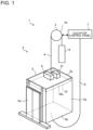
- Fig. 1 is a perspective view illustrating a configuration of an elevator 1 according to Embodiment 1.
- the elevator 1 is installed inside a building and configured to ascend or descend through a hoistway 2.
- a hoisting machine 3 is provided in an upper part of the hoistway 2.
- the hoisting machine 3 is provided with a sheave 3a. Over the sheave 3a, a main rope 4 is stretched.
- the main rope 4 has two ends that are coupled to a car 5 and a balancing weight 6, respectively.
- the car 5 and the balancing weight 6 are reversibly suspended from the sheave 3a by the main rope 4.
- an elevator control panel 7 is provided at the upper part of the hoistway 2.
- the elevator control panel 7 is connected to the hoisting machine 3 by a communication line and connected to the car 5 by a control cable 8.
- the control cable 8 transmits electric power and a control signal to the car 5.
- the control cable 8 will also be referred to as "tail cord”.
- the car 5 is made up of four side boards 5a, a floor board 5b, and a ceiling board 5c.
- the four side boards 5a are located on the right, left, front, and back sides, respectively.
- a car door 5d is installed at the front side board 5a of the four side boards 5a.
- the car door 5d performs opening and closing operations in engagement with an elevator hall door (not illustrated) installed in the elevator hall.
- a car control device 9 and a sound-field control device 21 are provided on an upper surface of the ceiling board 5c of the car 5, as illustrated in Fig. 1 .
- the car control device 9 controls operations of devices provided in the car 5.
- the devices provided in the car 5 are, for example, the car door 5d, a lighting device 5e (see Fig. 2 ), and a car operation panel 5f (see Fig. 2 ).
- the sound-field control device 21 controls the overall operation of a closed space sound system 13 (see Fig. 3 ) that will be described later, in such a way as to produce a stereoscopic sound field 27 (see Fig. 3 ) in the entire internal space of the car 5.
- the closed space sound system 13 will be hereinafter simply referred to as "sound system 13".
- a suspended ceiling 10 is fixed to a lower surface of the ceiling board 5c of the car 5, as illustrated in Fig. 1 .
- the suspended ceiling 10 is located in the internal space of the car 5.
- the suspended ceiling 10 has a cuboidal shape.
- the suspended ceiling 10 has four side surfaces 10a and a lower surface 10b (see Fig. 2 ).
- the suspended ceiling 10 may further have an upper surface that is located opposite to the lower surface 10b.
- the lighting device 5e see Fig. 2
- an emergency speaker 5g see Fig. 2
- a speaker system 22 of the sound system 13 see Fig. 3
- the sound-field control device 21 is provided on the upper surface of the ceiling board 5c of the car 5 as illustrated in Fig. 1 , the sound-field control device 21 may be also provided in the internal space of the suspended ceiling 10. Between the side surfaces 10a of the suspended ceiling 10 and the side boards 5a of the car 5, a gap 11 having a certain gap distance D (see Figs. 2 and 3 ) is provided.
- the certain gap distance D is will be hereinafter referred to as "first gap distance D".
- Fig. 1 illustrates an example in which the elevator 1 is a rope elevator, this illustration is not limiting.
- the elevator 1 may, for example, be another type of elevator such as a linear motor elevator.
- Fig. 2 illustrates an appearance of an internal space of the car 5 of the elevator 1 according to Embodiment 1.
- the internal space of the car 5 is surrounded by the four side boards 5a, the floor board 5b, and the lower surface 10b of the suspended ceiling 10.
- the internal space of the car 5 is, for example, cuboid.
- the floor board 5b has a flat rectangular surface extending in a horizontal direction.
- Each of the side boards 5a has a flat rectangular surface extending in a perpendicular direction.
- the "perpendicular direction" means, for example, a vertical direction.
- the lower surface 10b of the suspended ceiling 10 is provided to face the floor board 5b.
- the lower surface 10b of the suspended ceiling 10 is a rectangular flat surface extending in the horizontal direction.
- the suspended ceiling 10 is provided with the lighting device 5e.
- a main body of the lighting device 5e is provided in the internal space of the suspended ceiling 10.
- the lighting device 5e is, for example, an LED lighting device.
- the lighting device 5e has an illumination surface 5ea that faces the floor board 5b.
- the lighting device 5e illuminates the internal space of the car 5 with light radiated from the illumination surface 5ea.
- an emergency speaker 5g is provided at the suspended ceiling 10.
- the emergency speaker 5g is provided to make an emergency announcement from a management office of the building. In addition to the emergency announcement, the emergency speaker 5g may also be used to send a voice message such as "the door will close" to a passenger.
- the car door 5d is provided at the front side board 5a of the four side boards 5a.
- the car operation panel 5f is provided at the front side board 5a.
- the car operation panel 5f is provided with a plurality of car call registration buttons that are provided in association with respective floors and door opening and closing buttons that are provided to control opening and closing operations of the car door 5d.
- the car operation panel 5f is provided with an interphone device 5h that enables a passenger to communicate with a person who is present outside the car, in case of emergency.
- the car control device 9 is connected to the elevator control panel 7, for example, by the control cable 8 (see Fig. 1 ).
- the car control device 9 includes an input unit 9a, a control unit 9b, an output unit 9c, and a storage unit 9d.
- the input unit 9a inputs a control signal transmitted from the elevator control panel 7 to the control unit 9b.
- the control unit 9b controls operations of the devices provided in the car 5.
- the output unit 9c outputs driving signals to the respective devices.
- the output unit 9c transmits, to the elevator control panel 7, a signal for, for example, car call registration that is inputted from the passenger to the car operation panel 5f.
- the storage unit 9d stores therein the result of a calculation made by the control unit 9b and various types of data and programs for use in the control by the control unit 9b.
- the sound-field control device 21 is one of the components included in the sound system 13.
- the sound system 13 includes the sound-field control device 21 and a speaker system 22 which will be described later.
- the sound-field control device 21 includes a sound-field control unit 21a, an output unit 21b, a storage unit 21c, and a timer unit 21d.
- the sound-field control unit 21a controls the operation of the sound system 13 to produce a high sound-quality sound field in the internal space of the car 5.
- the output unit 21b Under control by the sound-field control unit 21a, the output unit 21b outputs a driving signal and playback data on a sound signal to a speaker cabinet 20.
- the storage unit 21c stores, for example, a plurality of sound sources generated in nature.
- the storage unit 21c may store in advance sound content 30 (see Fig. 11 ) that is obtained by combining sounds from the plurality of sound sources generated in nature.
- the storage unit 21c further stores the result of a calculation made by the sound-field control unit 21a and various types of data and programs for use in the control by the sound-field control unit 21a.
- the sound-field control unit 21a combines and plays back sound sources stored in the storage unit 21c, and causes a sound signal based on the sound sources to be radiated from the speaker system 22 toward the internal space of the car 5.
- the sound-field control unit 21a plays back the sound content 30 stored in the storage unit 21c and causes a sound signal based on the sound content 30 to be radiated from the speaker system 22 toward the internal space of the car 5.
- the sound-field control unit 21a causes a sound signal based on combined two or more sound sources to be radiated from the speaker system 22 toward the internal space of the car 5.
- the timer unit 21d counts the current date and time and retains current date-and-time data representing the current date and time.
- the timer unit 21d has, as date-and-time data, date data representing dates of an annual calendar and time data representing time.
- the sound-field control unit 21a may acquire date-and-time data from the timer unit 21d, and based on the date-and-time data, change the sound content 30 according to the season and the time zone for living.
- the sound content 30 is created, for example, by a sound content creating device 40 installed externally, and is stored in advance in the storage unit 21c.
- the sound content creating device 40 creates sound content 30 by combining a plurality of sound sources generated in nature.
- the sound content creating device 40 includes a signal processing unit 40b that executes a signal process on the sound content 30.
- the signal processing unit 40b executes one or more signal processes as needed. The timing at which such a signal process is executed may precede or follow the combining of sound sources.
- the sound content creating device 40 includes an output unit 40a, a storage unit 40c, and an input unit 40d.
- the input unit 40d receives sound data obtained from a sound source generated in nature.
- the sound data may be data created based on data actually recorded in nature, or may be artificially created pseudo-data.
- the output unit 40a outputs created sound content 30.
- the storage unit 40c stores the result of a calculation by the signal processing unit 40b and various types of data and programs for use in the control by the signal processing unit 40b.
- the processing circuit is dedicated hardware or a processor.
- the dedicated hardware is, for example, an application specific integrated circuit (ASIC), a field programmable gate array (FPGA), or other hardware.
- the processor executes a program stored in a memory.
- the storage unit 9d is the memory.
- the memory is a nonvolatile or volatile semiconductor memory such as a random-access memory (RAM), a read-only memory (ROM), a flash memory, or an erasable programmable ROM (EPROM) or a disc such as a magnetic disc, a flexible disc, or an optical disc.
- the processing circuit is dedicated hardware or a processor. Descriptions concerning the dedicated hardware and the processor will be omitted, since they may be the same as the above dedicated hardware and processor.
- the storage unit 21c is the memory. A description concerning the memory will also be omitted, since it may be the same as the above memory.
- the processing circuit is dedicated hardware or a processor. Descriptions concerning the dedicated hardware and the processor will also be omitted, since they may be the same as the above dedicated hardware and processor.
- the storage unit 40c is the memory. A description concerning the memory will be omitted, since it may be the same as the above memory.
- Fig. 3 is a front view illustrating a configuration of the sound system 13 according to Embodiment 1.
- Fig. 4 is a top view illustrating the layout of speaker cabinets 20 included in the sound system 13 according to Embodiment 1. It is assumed that in Figs. 3 and 4 , the height direction of the car 5 is a Y direction, the width direction of the car 5 is an X direction, and the depth direction of the car 5 is a Z direction.
- the Y direction is, for example, the vertical direction. Furthermore, as illustrated in Fig.
- the right, left, front, and back of the inside of the car 5 are defined such that the X direction is a lateral direction of the car 5, that is, a direction from the left side or right side of the car 5 toward the right side or left side thereof, and the Z direction is a front-back direction of the car 5, that is, a direction from the front of the car toward the back of the car 5.
- the sound system 13 includes a speaker system 22 provided on a ceiling located above the closed space and the sound-field control device 21.
- the speaker system 22 includes one or more speaker cabinets 20.
- each of the speaker cabinets 20 includes one or more speaker units 23.
- the sound system 13 produces a sound field 27 and radiates sound to a passenger in the car 5.
- sounds from a plurality of sound sources naturally generated in nature such as the murmur of a river and the chirping of a bird, are used, and sound content formed by combining those sounds is used.
- a sound-field environment of a playback of two or more channels is created, and in the sound-field environment, sound content 30 (see Fig.
- the sound content 30 is created such that for example, seasons such as spring, summer, autumn, and winter and time periods of living such as dawn, daytime, evening, and nighttime that anyone who lives in Japan can experience can be sensed from sound.
- the sound content 30 will be described later.
- the above feature enables the passenger to obtain a sense of the time period and a sense of the season from "sound" even while being present in the closed space, which disables the passenger to look outside.
- the sound content 30 is created so as not to give the passenger a sense of bustle or other senses or contain uncomfortable factors such as noise, the sound content 30 does not give auditory discomfort to the passenger.
- the sound content 30 is a combination of a type of sound source, such as the flow of a wind or river and the singing of a bird, which is naturally generated in nature, a time period of living, and a frequency band.
- the number of speaker cabinets 20 included in the speaker system 22 is 2.
- the number of speaker cabinets 20 is not limited to 2 but may be any number larger than or equal to 1. This makes it possible to produce a sound field 27 of a playback of one or more channels in the closed space.
- each of the speaker cabinets 20 is provided in an internal space of the suspended ceiling 10.
- the speaker cabinet 20 includes a speaker unit 23 and a casing 25.
- the speaker system 22 may include just only one or more speaker units 23 without the speaker cabinet 20.
- the speaker units 23 and the speaker cabinets 20 may be provided at other positions such as the side boards
- Fig. 5 is a side view illustrating an example of the configuration of the speaker cabinet 20 according to Embodiment 1.
- Fig. 6 is a front view illustrating the configuration of the speaker cabinet 20 as illustrated in Fig. 5 .
- the speaker cabinet 20 includes the speaker unit 23 and the casing 25.
- the speaker unit 23 is housed in the casing 25.
- the speaker unit 23 has a radiation surface 23a which is formed at a front surface 25a of the casing 25 and from which sound is radiated outward.
- the casing 25 has, for example, a cuboidal shape.
- the casing 25 is a closed device in the air.
- the radiation surface 23a of the speaker unit 23 is fitted in an installation hole provided in the front surface 25a of the casing 25, and is exposed outward from the installation hole. Other parts of the speaker unit 23 are all located in the casing 25. Thus, the sound from the radiation surface 23a of the speaker unit 23 is radiated only in a direction indicated an arrow A in Fig. 5 , and is not radiated outward via the parts of the casing 25 that are other than the radiation surface 23a.
- Fig. 7 is a side view illustrating a configuration of a modification of the speaker cabinet 20 according to Embodiment 1.
- Fig. 8 is a front view illustrating a configuration of the speaker cabinet 20 as illustrated in Fig. 7 .
- two or more speaker units 23 may be housed in the casing 25.
- one speaker unit 23-1 may be a full-range speaker
- the other speaker unit 23-2 may be a tweeter.
- the full-range speaker is a speaker that plays back sound from a low-frequency range to a high-frequency range without another speaker or other speakers.
- the single speaker unit 23 is a full-range speaker.
- the tweeter is a speaker dedicated for a low frequency range and used as an aid to the full-range speaker. It is hard to play back sound from a low-frequency range to a high-frequency range with a single speaker. If the single speaker plays back sound from the low-frequency range to the high-frequency range, it is conceivable that the sound is played back with a poor quality. Therefore, in such a case, a tweeter is used to compensate for the poor sound quality.
- two or more speaker units 23 that are of different types may be installed in the casing 25 or two or more speaker units 23 that are of the same type may be installed in the casing 25.
- one speaker unit be a full-range speaker and the other speaker unit or units be speakers dedicated to a low-frequency or high-frequency range and used as aids to the full-range speaker. If the speaker units are set in such a manner, they can radiate sound over a wide frequency band from a low-frequency range to a high-frequency range and for each of narrow frequency bands.
- one speaker cabinet 20 includes a plurality of speaker units 23, the feeling of sound quality can be improved and sound can be played back over a wider frequency band with the speaker cabinet 20 solely. As a result, it is possible to easily achieve a "high sound quality system" that can cover a wide frequency band.
- the speaker cabinets 20 are provided in the internal space of the suspended ceiling 10.
- the height of the suspended ceiling 10 in the Y direction (the height direction of the car 5) is, for example, approximately 5 cm. Therefore, as illustrated in Fig. 3 , the height H1 of the casing 25 of each of the speaker cabinets 20 in the Y direction (the height direction of the car 5) is less than or equal to 5 cm. Thus, the height H1 of the casing 25 is restricted by the height of the suspended ceiling 10 in the Y direction (the height direction of the car 5).
- the radiation surface 23a of the speaker unit 23 is located to face a side board 5a of the car 5.
- the radiation surface 23a is located along a side surface 10a of the suspended ceiling 10.
- the radiation surface 23a is located in the same plane as the side surface 10a of the suspended ceiling 10. Therefore, the position of the radiation surface 23a in the X direction (the width direction of the car 5) coincides or substantially coincides with the position of the side surface 10a of the suspended ceiling 10 in the X direction.
- an opening is provided such that its position coincides with the position of the radiation surface 23a. It should be noted that the entire side surface 10a of the suspended ceiling 10 may be open. Therefore, the sound radiated from the radiation surface 23a is not shut out by the side surface 10a of the suspended ceiling 10.
- a gap 11 having the first gap distance D1 is provided between the side surface 10a of the suspended ceiling 10 and the side board 5a of the car 5.
- the first gap distance D is approximately 5 cm. It should be noted that the first gap distance D is set as appropriate in the range of 2 to 20 cm, and preferably, should be set as appropriate according to the specifications of the car 5 of the elevator 1 in the range of 3 to 10 cm.
- the sound from the radiation surface 23a of the speaker unit 23 is radiated in the direction indicated by an arrow A. After that, the sound is reflected from the side board 5a of the car 5 as reflected sound. As illustrated in Figs.
- the reflected sound travels in the direction indicated by an arrow B.
- the speaker unit 23 performs "indirect sound radiation" in which the radiated sound is reflected from the side board 5a of the car 5 to the passenger.
- the radiation surface 23a of the speaker unit 23 is located close to the side board 5a of the car 5 and faces the side board 5a of the car 5. To be more specific, the radiation surface 23a is separated from the side board 5a by the gap 11 having the first gap distance D. As described above, the first gap distance D is approximately 5 cm. Therefore, the sound radiated from the radiation surface 23a of the speaker unit 23 is reflected from the side board 5a of the car 5 immediately after being radiated from the radiation surface 23a and before being reduced in sound pressure level.
- each of the speaker cabinets 20 is provided backward from a central portion of the suspended ceiling 10 in the Z direction (the depth direction of the car 5).
- the speaker cabinet 20 may be provided at the central portion of the suspended ceiling 10 in the Z direction, or may be provided forward from the central portion of the suspended ceiling 10 in the Z direction.
- the speaker cabinet 20 is provided at a central portion of the suspended ceiling 10 in the Y direction (the height direction of the car 5). This, however, is not limiting, and the speaker cabinet 20 may be provided at a higher level than the central portion of the suspended ceiling 10 in the Y direction or may be provided at a lower level than the central portion.
- the speaker unit 23 provided in one of the two speaker cabinets 20 as illustrated in Fig. 4 will be referred to as “speaker unit 23R", and the speaker unit 23 provided in the other speaker cabinet 20 will be referred to as “speaker unit 23L”.
- the speaker unit 23R and the speaker unit 23L are separated from each other.
- the speaker cabinet 20 which houses the speaker unit 23R and the speaker cabinet 20 which houses the speaker unit 23L are separated from each other by a certain distance with reference to a central portion of the suspended ceiling 10 in the X direction.
- the certain distance will be referred to as "second distance D2”.
- the second distance D2 is determined based on the dimension of the car 5 in the X direction, the first gap distance D, and the dimension of the casing 25 in the X direction.
- the speaker unit 23R and the speaker unit 23L are arranged such that their back surfaces face each other. Therefore, as illustrated in Fig. 4 , the radiation surface 23a of the speaker unit 23R is located to face the right side board 5a of the car 5, and the radiation surface 23a of the speaker unit 23L is located to face the left side board 5a of the car 5. Each of the radiation surfaces 23a of the speaker units 23R and 23L is located to face the gap 11. Each of the radiation surfaces 23a of the speaker units 23R and 23L is located in the same plane as an associated one of the right and left side surfaces 10a of the suspended ceiling 10.
- the passenger stands while facing the car door 5d.
- the sound radiated from the speaker unit 23R travels mainly to the right ear of the passenger
- the sound radiated from the speaker unit 23L travels mainly to the left ear of the passenger.
- the sound radiated from the speaker unit 23R will be referred to as "right-side sound”
- the sound radiated from the speaker unit 23L will be referred to as "left-side sound”.
- Fig. 9 is a front view schematically illustrating a configuration of a modification of the sound system 13 according to Embodiment 1.
- two speaker units 23R-1 and 23L-1 are located opposite to the floor board 5b of the car 5.
- the radiation surfaces 23a of the speaker units 23R-1 and 23L-1 are located to face the floor board 5b of the car 5 as illustrated in Fig. 9 .
- the speaker cabinet 20 which houses the speaker unit 23R-1 and the speaker cabinet 20 which houses the speaker unit 23L-1 are separated from each other by a certain distance with reference to the central portion of the suspended ceiling 10 in the X direction.
- the certain distance will be referred to as "third distance D3".
- the third distance D3 may be equal to or unequal to the second distance D2 which is indicated in Fig. 4 .
- each of the radiation surfaces 23a of the speaker units 23R-1 and 23L-1 is located in the same plane as the lower surface 10b of the suspended ceiling 10. Therefore, the position of the radiation surface 23a in the Y direction (the height direction of the car 5) coincides or substantially coincides with the position of the lower surface 10b of the suspended ceiling 10 in the Y direction. Furthermore, the radiation surfaces 23a of the speaker units 23R-1 and 23L-1 are fitted in attachment holes provided in the lower surface 10b of the suspended ceiling 10. Each of the radiation surfaces 23a of the speaker units 23R-1 and 23L-1 is exposed from an associated one of the attachment holes to the outside thereof. Accordingly, sound radiated from each of the radiation surfaces 23a of the speaker units 23R-1 and 23L-1 is not shut out by the lower surface 10b of the suspended ceiling 10.
- the sound from the speaker units 23R-1 and 23L-1 is radiated from the radiation surfaces 23a in the directions indicated by arrows A.
- the speaker units 23R-1 and 23L-1 perform "direct sound radiation" in which the speaker units 23R-1 and 23L-1 radiate sound from the suspended ceiling 10 directly to the passenger.
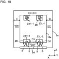
- Fig. 10 is a plan view schematically illustrating a configuration of another modification of the sound system 13 according to Embodiment 1.
- Fig. 10 illustrates the lower surface 10b of the suspended ceiling 10, as viewed from a side where the floor board 5b is located.
- four speaker units 23R-1, 23R-2, 23L-1, and 23L-2 are provided.
- the speaker units 23R-2 and 23L-2 are located opposite to the front side board 5a of the car 5, and the other two speaker units 23R-1 and 23L-1 are located opposite to the floor board 5b of the car 5.
- the radiation surfaces 23a of the speaker units 23R-1 and 23L-1 are located to face the floor board 5b of the car 5 as illustrated in Fig. 9 .
- the two front speaker units 23R-2 and 23L-2 are located opposite to the front side board 5a of the car 5.
- the speaker cabinet 20 which accommodates the speaker unit 23R-2 and the speaker cabinet 20 which accommodates the speaker unit 23L-2 are separated from each other by a certain distance from each other with reference to the central portion of the suspended ceiling 10 in the X direction.
- the certain distance may, for example, be equal to or unequal to the third distance D3 indicated in Fig. 9 .
- each of the radiation surfaces 23a of the speaker units 23R-2 and 23L-2 is provided to face an associated one of the side boards 5a of the car 5. Furthermore, each of the radiation surfaces 23a is located along an associated one of the side surfaces 10a of the suspended ceiling 10. Therefore, the position of the radiation surface 23a in the Z direction (the depth direction of the car 5) coincides or substantially coincides with the position of the associated side surface 10a of the suspended ceiling 10 in the Z direction.
- the gap 11 having the first gap distance D is provided between the side board of the suspended ceiling 10 and the side board 5a of the car 5.
- the sound radiated from the speaker units 23R-2 and 23L-2 is radiated from the radiation surfaces 23a in the directions indicated by arrows.
- the sound is reflected from the side boards 5a of the car 5 as reflected sound.
- the reflected sound travels in the directions indicated by arrows B.
- the speaker units 23R-2 and 23L-2 perform "indirect sound radiation" in which the sound from the suspended ceiling 10 is reflected from the side boards 5a of the car 5 to the passenger.
- the two back speaker units 23R-1 and 23L-1 are located opposite to the floor board 5b of the car 5.
- the two back speaker units 23R-1 and 23L-1 performs "direct sound radiation” in which the two back speaker units 23R-1 and 23L-1 radiate sound from the suspended ceiling 10 directly to the passenger.
- "indirect sound radiation” and “direct sound radiation” may be performed in combination as in the modification as illustrated in Fig. 10 .
- the speaker units 23R and 23L as illustrated in Fig. 4 may be provided instead of the speaker units 23R-2 and 23L-2.
- Each of the speaker units 23 may be installed at any position on the lower surface 10b of the suspended ceiling 10 in the car 5.
- the speaker units 23 are installed in any of the following manners: right and left speaker units 23 are installed as illustrated in Fig. 4 ; front and back speaker units 23 are installed; and speaker units 23 are installed at corners of the lower surface 10b of the suspended ceiling 10.
- These manners of installation off the speaker units 23 can be freely combined.
- the speaker units 23 be separated from each other to some extent. Therefore, in Embodiment 1, the speaker cabinets 20 which accommodate the speaker units 23 are separated from each other by the second distance D2 or the third distance D3.
- the speaker cabinet 20 can be installed in the floor board 5b of the car 5.
- the body of the passenger per se is a sound absorber and a reflector for sound
- a sound signal output from a location below the passengers cannot easily arrive at the passengers' ears.
- a sound field 27 based on the playback of sound having a high quality cannot be produced in the car 5.
- the speaker cabinet 20 is installed at a higher level than the chest of the passenger in order that sound be played back with a high quality. Therefore, it is preferable that the speaker cabinet 20 be installed, for example, in the suspended ceiling 10 or the upper part of the side board 5a of the car 5.
- the sound system 13 produces a sound field 27 in, for example, a range indicated by dotted lines in Fig. 3 .
- the level H2 of a lower limit 27a of the sound field 27 is, for example, approximately 1.0 to 1.7 m from the floor board 5b of the car 5, and preferably, should be 1.6 m.
- the level of an upper limit of the sound field 27 is, for example, 1.8 m from the floor board 5b of the car 5.
- the sound field 27 be produced such that the level of the sound field 27 from the floor board 5b falls within the range of 1.6 to 1.8 m.
- the sound field 27 is produced in a region in the car 5 that is higher in level than the lower limit 27a.
- the sound field 27 is produced around the head of the passenger as illustrated in Fig. 3 .
- the level H2 of the lower limit 27a of the sound field 27 is set based on the average height of passengers (excluding passengers of junior high school age or younger). In the range of 0 m to less than 1.6 m from the floor board 5b, a satisfactory sound field cannot be produced if a large numbery of passengers get on the car 5, as sound is shut out or absorbed by the passengers as described above. In the range of 1.8 m or higher from the floor board 5b, the passenger does not easily hear the sound, because the sound field 27 is produced over the head of the passenger.
- the range of production of the sound field 27 is not limited to the range of 1.6 to 1.8 m.
- the level H2 of the lower limit 27a of the sound field 27 fall within the range of, for example, 1.0 to 1.7 m from the floor board 5b of the car 5.
- the sound content 30 is a sound signal that is output from the speaker system 22 under control by the sound-field control unit 21a.
- Fig. 11 illustrates an example of the configuration of the sound content 30 according to Embodiment 1.
- the upper part of Fig. 11 illustrates sound content 30 that is output from the speaker unit 23L as illustrated in Fig. 4
- the lower part of Fig. 11 illustrates sound content 30 that is output from the speaker unit 23R as illustrated in Fig. 4
- the sound content 30 output from the speaker unit 23L and the sound content 30 output from the speaker unit 23R may be different from each other as illustrated in Fig. 11 , but may be the same as each other.
- Fig. 11 may be different from each other as illustrated in Fig. 11 , but may be the same as each other.
- the horizontal axis represents time
- the vertical axis represents sound pressure level.
- the sound content 30 includes a background sound 31 and an additional sound 32 that is added to the background sound 31.
- the sound content 30 is divided into a plurality of time segments 33.
- the boundaries between the time segments 33 are indicated by dashed lines.
- the entire time length of the sound content 30 is 90 sec, and over the entire time length of the sound content 30, the time thereof is divided into twelve segments 33.
- the number of time segments 33 is not limited to twelve, but are set as appropriate.
- time lengths of the time segments 33 are each set to one of at least two time lengths.
- reference signs for time such as “2S”, “8S”, and “5S”, denote the respective time lengths of the time segments 33.
- “2S” means two seconds.
- the time segments 33 are set to have respective time lengths as appropriate.
- the background sound 31 is set to be continuously radiated in all of the plurality of time segments 33. Furthermore, additional sounds 32 are separately set for each of the time segments 33 and are radiated separately for each of the time segments 33.
- the additional sound 32 is higher in sound pressure level than the background sound 31. Furthermore, as illustrated in the example illustrated in Fig. 11 , the additional sounds 32 are set for not all the time segments 33, and there are time segments 33 for which additional sounds 32 are not set. In the example illustrated in Fig.
- time segments 33 in each of which an additional sound 32 is added (which will be each hereinafter referred to as "first time segment") and time segments 33 in each of which an additional sound 32 is not added (which will be each hereinafter referred to as “second segment time”) are alternately arranged for the reason that if additional sounds 32 are added to all the time segments 33, the passenger is highly likely to have a "noisy" impression about the additional sounds 32.
- the time segments 33 are arranged such that at least one of any two adjacent time segments 33 is a second time segment in which no additional sound is added. That is, at least one second time segment is provided between any adjacent first time segments.
- two or more second time segments may be arranged in series.
- the sound content 30 includes a prelude part 34 including one or more time segments 33, a postlude part 36 including one or more time segments, and an interlude part 35 that is set between the prelude part 34 and the postlude part 36 and that includes a single time segment.
- the prelude part 34 includes five time segments 33
- the interlude part 35 includes a single time segment 33
- the postlude part 36 includes six time segments 33. This, however, is merely an example, and is not limiting.
- the interlude part 35 may include two or more time segments 33.
- Fig. 11 illustrates time changes in sound content 30 which is a fundamental sound source obtained through a mix-down of a plurality of sound sources combined.
- the entire time length of the sound content 30 (that is, a sound signal) is shorter than or equal to two minutes. That is, the entire time length of the sound content 30 is two minutes at the maximum (that is, 120 seconds).
- the time for which the car 5 of the elevator 1 is moved upward or downward depends on the height of the building. However, in many cases, even in a tall building, the time for which the car 5 is moved is approximately two minutes or shorter for the following reason.
- the space in the car 5 is a closed space. If passengers are restrained for a long time in such a closed space, the passengers are continuously under stress, as they cannot move their own ways.
- Embodiment 1 the entire time length of single sound content 30 is set as appropriate to two minutes or shorter.
- the sound content 30 the time length of which is two minutes or shorter is repeatedly and continuously played back in the car 5 under control by the sound-field control unit 21a. In this way, the sound content 30, which is repeatedly played back, is created to have a melody that changes in a certain cycle.
- the car 5 moves upward or downward, and stops in response to a passenger's button operation at the floor designated by the passenger, and meanwhile, the sound content 30 is repeatedly played back. Therefore, the passenger does not necessarily listen to the sound content 30 from the beginning. Some passenger may get on the elevator 1 halfway through the sound content 30 being played back. Furthermore, for example, in many cases, the passenger may use the elevator 1 to move from a given floor to another floor through one floor or more, for example, from the first floor to the tenth floor; however, some passenger may use the elevator 1 to move from a given floor to the next floor, for example, from the fourth floor to the fifth floor.
- the elevator of Embodiment 1 radiates sound content 30 that does not give stress or an uncomfortable feeling, for example, even to a passenger who uses the elevator 1 to move from a given floor to the next floor.
- the elevator uses a "naturally generated sound” having no specific meaning, that is, a "meaningless sound”, not “meaningful sound”. In the case of playing back "meaningless sound", even if the passenger is forced to stop listening to the sound halfway through the playback of the sound, it is highly unlikely that the passenger will get stressed.
- the sound content 30 is a combination of a plurality of sound sources generated in nature.
- the sound sources are numbered as, for example, sound sources (1) to (7) as indicated below, and the sound content 30 is a combination of these sound sources.
- the sound sources (1) to (3) are sound sources that are combined to create the background sound 31 as illustrated Fig. 11 , and provide sounds that cause the passenger to call up an image of a state of an environment of the nature.
- the sound sources (1) to (3) are sound sources which are generated in the environment of the nature (which will be hereinafter referred to as "first sound sources”). Sounds from the sound sources (1) to (3) are sounds generated from the first sound sources, that is, sounds based on states of environments of the nature.
- sounds from the sound sources (4) to (7) are sounds that are combined to create the additional sound 32 as illustrated in Fig. 11 , and are sounds that cause the passenger to call up an image of actions of living creatures of the nature.
- the sound sources (4) to (7) are sound sources which are generated by living creatures living in the nature (which will be hereinafter referred to as "second sound sources”).
- the sounds from the sound sources (4) to (7) are sounds generated from the second source sources, that is, sounds based on actions of the living creatures in the nature.
- the sound content 30 as illustrated in Fig. 11 is sound content (a) evaluated as the most comfortable sound content according to evaluation results indicated in Figs. 22 and 23 , which will be described later.
- signs such as "(2)" and “(4)” each indicate which of the above sound sources (1) to (7) is set for each of the time segments 33.
- the sign "(4) (2)" indicates a combination of a background sound 31 and an additional sound 32.
- signs "(1)+(3)” and “(4)+(5)” indicate a combination of background sounds 31 or a combination of additional sounds 32.
- FIG. 11 illustrates sound content 30 that is output from the speaker unit 23L as illustrated in Fig. 4 .
- a background sound 31 corresponding to the sound source (2) is set successively for all the time segments 33.
- an additional sound 32 corresponding to the sound source (4) is added, and in a fourth time segment 33, an additional sound 32 corresponding to the sound source (6) is added.
- the additional sound corresponding to the sound source (4) and an additional sound 32 corresponding to the sound source (5) are added.
- the additional sound 32 corresponding to the sound source (4) is added.
- Lower part of Fig. 11 illustrates sound content 30 that is output from the speaker unit 23R as illustrated in Fig. 4 .
- a background sound 31 corresponding to a combination of the sound source (1) and the sound source (3) is set successively for all the time segments 33.
- the additional sound 32 corresponding to the sound source (4) is added, and in the fourth time segment 33, the additional sound 32 corresponding to the sound source (6) is added.
- the additional sound corresponding to the sound source (4) and the additional sound 32 corresponding to the sound source (5) are added.
- the additional sound 32 corresponding to the sound source (4) is added.
- a very-low-volume additional sound 32 corresponding to the sound source (5) is added to the background sound 31.
- a very-low-volume additional sound 32 corresponding to the sound source (7) is added to the background sound 31.
- the sound pressure levels of these additional sounds 32 are substantially equal to the sound pressure level of the background sound 31.
- at least one second time segment in which no additional sound is added is provided between any adjacent first time segments in each of which an additional sound is added.
- an exceptional second time segment in which a very-low-volume additional sound 32 is added may be provided between adjacent first time segments.
- reference signs for time such as "2S”, “8S”, and “5S”, denote the respective time lengths of the time segments 33.
- time segments 33 not all the time segments 33 have the same time length, and all the time segments 33 are each set to have one of two or more time lengths determined as appropriate.
- the kinds of time length of the time segments 33 are not limited to those illustrated in Fig. 11 .
- the time lengths of the time segments 33 may be each set to have a predetermined fluctuation range with respect to the time lengths indicated.
- a time segment 33 whose time length is longer than or equal to six seconds may be set with a fluctuation range of -5 seconds at the maximum, and a time segment 33 whose time length is shorter than six seconds may be set with a fluctuation range of up to +3 seconds at the maximum.
- the range of fluctuation is an allowable range for keeping the sound comfortable.
- the allowable range is the range of 3 to 8 seconds.
- the time segment 33 corresponding to the interlude part 35 of the sound content 30 has the longest time length.
- the longest time length is "15S”.
- the longest one of the time lengths of the time segments 33 corresponding to the prelude part 34 will be referred to as a first time length.
- the first time length is "8S”.
- the longest one of the time lengths of the time segments 33 in each of which an additional sound is added is "5S”.
- the longest one of the time lengths of the time segments 33 corresponding to the postlude part 36 will be referred to as a second time length.
- the second time length is "9S".
- the longest one of the time lengths of the time segments 33 in each of which an additional sound is added is "5S”.
- the time length of the time segment 33 corresponding to the interlude part 35 will be referred to as a third time length.
- the third time length is "15S”.
- the third time length is set to be longer than the first time length and the second time length.
- the total time length of additional sounds 32 in the time segment 33 corresponding to the interlude part 35 is longer than those in the time segments 33 corresponding to the prelude part 34 and the postlude part 36.
- additional sounds 32 that are longish in time length are provided before and behind an intermediate point of the entire sound content 30.
- an additional sound 32 that is long in length is provided at an early stage of the output of sound, when a passenger gets on an elevator 1 that can play back sound contents 30, for the first time, the above long additional sound 32 surprises the passenger to make him or her uncomfortable. Therefore, a longish additional sound 32 is provided halfway through the operation of the elevator 1, and as a result, the boredom of the passenger in the elevator 1 is reduced.
- the sound content 30 By playing back sound content 30 including additional sounds 32 in the car 5, it is possible to reduce the "sense of tension" that keeps unwanted silence that brings peculiar "awkwardness” in the elevator 1. Therefore, the sound content 30 according to Embodiment 1 utilizes sounds from nature. Furthermore, a series of sounds of the sound content 30 gradually change in intensity over time, for example from the prelude part 34, through the interlude part 35, to the postlude part 36, as well as ordinary music. Specifically, in the sound content 30, the interlude part 35 is the highest in sound pressure level of the additional sounds 32 and the longest in time length of the additional sounds 32.
- the maximum value of the sound pressure levels of the additional sounds 32 in the time segments 33 corresponding to the prelude part 34 is a first level
- the maximum value of the sound pressure levels of the additional sounds 32 in the time segments 33 corresponding to the postlude part 36 is a second level
- the maximum value of the sound pressure levels of the additional sounds 32 in the time segment 33 corresponding to the interlude part 35 is a third level.
- the third level is set higher than the first level and the second level. In the example illustrated in Fig. 11 , the third level is set approximately 1.5 times to four times higher than the first level and the second level.
- the passenger listens to an additional sound 32 having a high pressure level in the interlude part 35 after listening to an additional sound 32 having a low pressure level in the prelude part 34.
- the passenger listens to additional sounds 32 that change in sound intensity with the passage of time, and thus does not listen sounds that suddenly change in sound intensity.
- the passenger can listen to played-back sound of the sound content 30 without feeling a sense of incongruity.
- the maximum value of the sound pressure levels of the additional sounds 32 in the time segment 33 corresponding to the interlude part 35 is the third level
- the average value of the sound pressure levels of the additional sounds 32 in the time segment 33 corresponding to the interlude part 35 may be the third level.
- the background sound 31 is always inserted separately from the additional sound 32 as a base signal in all the time segments 33.
- the sound pressure level of the background sound 31 is set lower than the sound pressure level of the additional sound 32.
- the sound pressure level of the background sound 31 is defined by a difference in numerical value between the background sound 31 and the additional sound 32.
- the sound pressure level of the additional sound 32 is made higher than that of the background sound 31 by 10 dB or higher.
- the upper limit is set to approximately 20 dB.
- the sound pressure level of the additional sound 32 is made higher than the sound pressure level of the background sound 31 in the range of +10 to +20 dB (instantaneous). This causes the additional sound 32 to be provided as a signal having a clear sound pressure level with reference to the background sound 31.
- the elevator 1 may be used to move from a certain floor to the next floor or the next floor but one. In such a case, as described above, the elevator 1 is used for a very short period of time, for example, 10 seconds to 20 seconds. In these cases, for example, a control operation may be carried out such that playback of the interlude part 35 of the sound content 30 is skipped and only the prelude part 34 and the postlude part 36 are played back.
- the sound-field control unit 21a obtains, from the car control device 9, information on a switch operation that is performed on the car operation panel 5f by the passenger.
- the sound-field control unit 21a detects the passenger's switch operation based on the information and determines, from the switch operation, whether the elevator 1 is used for a short period of time or not.
- the sound-field control unit 21a determines, from information on these switch operations, that a passenger who got on the elevator 1 at the "fifth floor” uses the elevator 1 for a short period of time.
- the sound-field control unit 21a When determining that the elevator 1 is used for a short period of time, the sound-field control unit 21a performs such a control operation that the sound content 30 is played back with a skip of the interlude part 35. In such a manner, in Embodiment 1, it is also possible to carry out a control process of causing the passenger not to listen to sound of the interlude part 35, for example.
- Signal processes that are executed on a background sound 31 and an additional sound 32 that are included in sound content 30 will be described.
- Signal processes on the source sources are based on the following signal processes. However, it is not indispensable that these signal processes are carried out. It suffices that the signal processes are carried out as needed.
- a signal process that is executed on the background sounds 31 corresponding to the foregoing sound sources (1) to (3) will be described. Phase processes such as reverb control and panning are not executed on the background sounds 31 corresponding to the foregoing sound sources (1) to (3).
- a signal process may be executed on the background sound 31. Specifically, in order that the passenger could obtain an auditory sense of spread of sound, at least one of the following two signal processes (i) and (ii) may be executed on right and left signals of the background sound 31.
- the signal process (i) will be described.
- the upper part indicates the left signal
- the lower part indicates the right signal.
- the sound pressure levels of parts of the background sound 31 that are surrounded by dashed ellipses 37 are slightly high.
- the sound pressure levels of parts of the background sound 31 that are surrounded by dashed ellipses 38 are slightly high.
- the right signal of the lower part slightly lags behind the left signal of the upper part.
- the background sound 31 of the right signal is given a delay time such that the background sound 31 of the right signal lags behind the background sound 31 of the left signal.
- the delay time is longer than 0 ms, and is appropriately set shorter than or equal to 300 ms. This makes it possible to give the passenger a sense of spread of sound.
- the left signal is output at an earlier timing than the right signal
- the right signal may be output at an earlier timing than the left signal.
- the sound pressure level of the background sound 31 of the right signal of the lower part is slightly higher than that of the background sound 31 of the left signal of the upper part.
- the sound pressure level of the right signal is given a gain difference such that the right signal is higher in sound pressure level than the left signal.
- the absolute value of the difference between the sound pressure level of the right signal and the sound pressure level of the left signal falls within the range from 3 dB to 6 dB. This can cause the passenger to have a sense of spread of sound.
- the right signal is higher in sound pressure level than the left signal, since most people have their right eyes as their dominant eyes; however, the left signal may be higher in sound pressure level than the right signal.
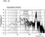
- Fig. 12 illustrates frequency characteristics that are obtained when fast Fourier transform (FFT) processing is executed on time waveforms at a point (B) indicated in Fig. 11 . That is, Fig. 12 illustrates the instantaneous frequency characteristics of the additional sound 32.
- Fig. 13 illustrates instantaneous frequency characteristics that are obtained when the FFT processing is executed on time waveforms at a point (A) in Fig. 11 . That is, Fig. 13 illustrates the instantaneous frequency characteristics of the background sound 31.
- the horizontal axis represents frequency
- the vertical axis represents sound pressure level.
- the sound pressure level of the additional sound 32 as illustrated in Fig. 12 is higher than that of the background sound 31 as illustrated in Fig. 13 . That is, in Embodiment 1, the sound pressure level of the additional sound 32 is given a gain difference greater than or equal to ⁇ 10 dB such that the additional sound 32 is higher in sound pressure level than the background sound 31.
- the passenger listens to sound that changes in sound pressure level in the above manner, he or she surely recognizes the sound of a frequency band whose sound pressure level has changed, and potentially has an attitude to try to listen to the sound of the frequency band. As a result, the passenger can change his or her mood by concentrating on listening to the sound.
- a change in sound pressure level is made in a frequency band of 2000 to 10000 Hz
- this is not limiting. That is, it is important to cause the sound pressure level to change in a frequency band of 800 Hz and higher.
- an easily audible frequency band for humans is a band of 800 to 15 kHz (range defined by a frame indicated by a dotted line in each of Figs. 12 and 13 ).
- frequencies of this band it is possible to cause the passenger to pay attention to the sound and also possible to utilize a physiological reaction to try to listen to the sound.
- it is also possible to perform a control for causing the passenger to increase interest in the sound.
- the frequency of the additional sound 32 is set higher than or equal to 800 Hz.
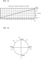
- Figs. 14 to 16 each illustrate an example of the case where a signal process is executed on an additional sound 32 included in the sound content 30 according to Embodiment 1.
- a panning process is executed on right and left signals.
- the horizontal axis represents time, and the vertical axis represents angle.
- Fig. 14 illustrates the case where a panning process is executed to make the passenger feel as if a sound source moved from right to left.
- Fig. 15 is an explanatory view for explanation of the principle of the panning process according to Embodiment 1.
- a stereo widening process is executed as a signal process.
- the horizontal axis represents time, and the vertical axis represents the percentage of stereo widening.
- Fig. 16 illustrates the case where such a phase control process as to enable "widening" and "sense of narrowness" to be repeatedly obtained in the entire time length of the sound content 30 is executed.
- Fig. 17 is an explanatory view for explanation of the principle of the stereo widening process according to Embodiment 1.
- the signal processes as illustrated in Figs. 14 and 16 are executed as needed on a sound source included in the sound content 30.
- signal processes such as the panning process and the stereo widening process are executed as needed. It is assumed that in the case where a signal process is executed, it is done based on an auditory sense, and at least any one of the following two signal processes (iii) and (iv) is executed.
- the panning process as illustrated in Fig. 14 causes the pan of the right and left signals of the additional sound 32 to change in the range of 90 degrees to -90 degrees within the entire time length (for example, 90 seconds) of the sound content 30. This gives the passenger an impression as if a sound source moved from right to left. Therefore, when the panning process as illustrated in Fig. 14 is executed on the foregoing sound source (5), which is sound made by a bird when the bird beats its wings to fly, the passenger can have an impression as if the bird took wing and moved from right to left.
- the principle of the panning process illustrated in Fig. 14 will be described with reference to Fig. 15 .
- the "pan” means a position (localization) between right and left, from which sound is heard. That is, the “pan” means where to place a source of generation of a sound, between right and left.
- the “pan” is also referred to as "pan pot”.
- the center is indicated by 0 degree
- a position located on the left side is indicated by a negative numerical value
- a position located on the right side is indicated by a positive numerical value.
- the position of a point 50 is a position corresponding to 0 degree and is the center.
- the position of a point 52 is a position corresponding to 90 degrees
- the position of a point 54 is a position corresponding to -90 degrees.
- Moving of the pan rightward from the center indicated by the point 50 that is, moving the pan from the point 50, for example, to a point 51
- moving of the pan leftward from the center indicated by the point 50 that is, panning from the point 50, for example, to a point 53
- moving of the pan is also referred to as "panning”.
- the pans of the right and left signals of the additional sound 32 are changed from +90 degrees toward -90 degrees in the entire time length (for example, 90 seconds) of the sound content 30.
- the pans of the right and left signals of the additional sound 32 may be changed from -90 degrees toward +90 degrees in the entire time length (for example, 90 seconds) of the sound content 30.
- the stereo widening process as illustrated in Fig. 16 causes the right and left signals of the additional sound 32 to change in phase difference in the range of 20 to 240% within the entire time length (for example, 90 seconds) of the sound content 30.
- the case where the phase difference is 100% is a standard, and in the case where the phase difference is less than 100%, the passenger is given a "sense of narrowness". Meanwhile, in the case where a phase difference exceeds 100%, the passenger is given an impression as if the space expanded, and is thus given a "sense of widening".
- FIG. 16 illustrates an example in which a process is executed to repeatedly cause the passenger to have the "sense of widening" and the "sense of narrowness” within 90 seconds.
- the "sense of widening" gradually increases in 15 seconds of the first half
- the "sense of narrowness” gradually increases in 15 seconds of the second half.
- Fig. 17 is a plan view illustrating a positional relationship between a passenger 60 and speaker cabinets 20.
- Fig. 17 illustrates a state in which the passenger 60 is located in front of a midpoint 61 between a speaker unit 23R and a speaker unit 23L.
- a straight line 62 is a straight line connecting the speaker unit 23R and the passenger 60
- a straight line 63 is a straight line connecting the speaker unit 23L and the passenger 60.
- a straight line 64 is a straight line connecting a virtual speaker unit 23Rv and the passenger 60
- a straight line 65 is a straight line connecting a virtual speaker unit 23Lv and the passenger 60.
- the stereo widening process is a process that expands the ranges of the positions of the speaker units 23R and 23L which are perceived by the passenger 60 to the positions of the virtual speaker units 23Rv and 23Lv. That is, in the case where the stereo widening process is not executed on a sound signal, the passenger 60 can localize the sound signal in a range forming an angle ⁇ between the straight line 62 and the straight line 63. In the case where the stereo widening process is executed on a sound signal, the passenger 60 can localize the sound signal in a range forming an angle ⁇ between the straight line 64 and the straight line 65.
- the stereo widening process as illustrated in Fig. 16 causes the right and left signals of the additional sound 32 to be alternately "widened” and "narrowed" in the range of 20% to 240% within the entire time length (e.g. 90 seconds) of the sound content 30.
- the range is from 20% to 240%, this is not limiting. That is, it suffices to appropriately set in what range to execute the stereo widening process, and the range may, for example, be from 20% to 100%.
- the passenger 60 perceives those sounds as if sounds were radiated from the virtual speaker unit 23Rv and the virtual speaker unit 23Lv.
- Fig. 18 is a top view illustrating a positional relationship between the passenger and the speaker units according to Embodiment 1.
- the speaker unit 23 installed on the right side and diagonally in front of the passenger 70 will be referred to as "speaker unit 23R”
- the speaker unit 23 installed on the left side and diagonally in front of the passenger 70 will be referred to as "speaker unit 23L”.
- sound radiated from the speaker unit 23R turns into a direct sound R (reference sign 73) and a cross sound RL (reference sign 74), and the direct sound R and the cross sound RL arrive at the right and left ears 70R and 70L, respectively, of the passenger 70.
- the direct sound R reference sign 73
- the cross sound RL reference sign 74
- the cross sound RL is an indirect sound that arrives at the left ear 70L of the passenger 70 after propagating for a given period of time from the speaker unit 23R.
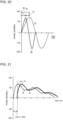
- Fig. 19 illustrates the waveforms of direct sounds and cross sounds according to Embodiment 1.
- the horizontal axis represents time, and the vertical axis represents phase.
- Fig. 19 illustrates the waveforms of the direct sound R (reference sign 73) received by the right ear 70R of the passenger 70, the direct sound L (reference sign 75) received by the left ear 70L of the passenger 70, the cross sound RL (reference sign 74) received by the left ear 70L of the passenger 70, and the cross sound LR (reference sign 76) received by the right ear 70R of the passenger 70.
- the horizontal axis represents time, and the vertical axis represents phase. As can be seen from Fig.
- Fig. 20 is a diagram for explanation of a time difference between two signals.
- the horizontal axis represents time
- the vertical axis represents phase.
- a signal having a wavelength 80 and a signal having a wavelength 81 are indicated, and the signal having a waveform 81 arrives at the right or left ear 70R or 70L of the passenger 70 later than the signal having a waveform 80. That is, in this case, a propagation time 82 of the waveform 80 is less than a propagation time 83 of the waveform 81.
- the difference between the propagation time 82 and the propagation time 83 is a time difference ⁇ t. It is possible to achieve the panning process as illustrated in Fig. 14 and the stereo widening process as illustrated in Fig. 16 , by executing a phase control process of, for example, increasing, decreasing, or zeroing the time difference ⁇ t.
- a component of cross sound causes the passenger to hear a sound image of sound radiated from the speaker units 23 such that the sound image is collected at the center of the cross component, that is, at a region between the right and left ears of the passenger.
- the passenger 70 be caused by the radiated sound to make an auditory illusion as if the narrow space in the car 5 were a wide space, it is necessary to let the passenger 70 hear the radiated sound as if the sound image were spreading.
- the cross sound is radiated, and then the direct sound is radiated with a time difference.
- Fig. 21 illustrates examples of the waveforms of sound waves subjected to the phase control process.
- the horizontal axis represents time
- the vertical axis represents phase.
- the time difference ⁇ t between the cross sound RL (reference sign 74) and the cross sound LR (reference sign 76) is eliminated.
- the time difference ⁇ t between the direct sound R (reference sign 73) and the direct sound L (reference sign 75) is eliminated.
- the cross sound RL (reference sign 74) and the cross sound LR (reference sign 76) are radiated first, and then the direct sound R (reference sign 73) and the direct sound L (reference sign 75) are radiated with a certain delay time.
- the passenger 70 is made to have an impression as if the sound image were spreading.
- the passenger 70 can hear, without feeling a sense of incongruity as if the sound field passed only over the head of the passenger 70, the sound radiated with the feeling of movement and the feeling of localization which can be obtained from the uniform phase.
- the time differences to be adjusted the following time differences are present: the time difference ⁇ t between the direct sound R (reference sign 73) and the direct sound L (reference sign 75); the time difference ⁇ t between the direct sound R (reference sign 73) and the cross sound LR (reference sign 76); the time difference ⁇ t between the direct sound L (reference sign 75) and the cross sound RL (reference sign 74): and the time difference ⁇ t between the cross sound LR (reference sign 76) and the cross sound RL (reference sign 74).
- An acoustic effect to be obtained depends on which of the above time differences ⁇ t is adjusted.
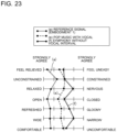
- Figs. 22 and 23 are each a schematic view illustrating human subjective and physiological evaluation results based on a semantic differential scale (SD) method.
- Figs. 22 and 23 show examples of subject experimental results obtained by evaluating the amounts of subjectivity of passengers in the elevator 1 which is actually operated, with respect to aptitude factors in the case of changing specifications of sound content 30. It should be noted that Fig. 11 illustrates sound content 30 which is evaluated to be most comfortable in the evaluation results indicated in Figs. 22 and 23 .
- SD semantic differential scale
- the results of evaluation of the sound content 30 are based on the SD method, by which the sound content is evaluated as impressions on sounds on a multiple-point scale using a plurality of pairs of adjectives indicated in Figs. 22 and 23 .
- the sound content 30 according to Embodiment 1 is highly evaluated.
- Figs. 22 and 23 show examples of the pairs of adjectives for use in the evaluation based on the SD method.
- seven pairs of adjectives were used to evaluate each of sound content on a five-point scale.
- the seven pairs of adjectives are specifically "FEEL RELIEEVED - FEEL UNEASY", "UNCONSTRAINED - CONSTRAINED”, “RELAXED - NERVOUS”, “OPEN - CLOSED”, “REFRESHED - GLOOMY”, “WIDE - NARROW”, and “COMFORTABLE - UNCOMFORTABLE”.
- evaluation was also made with respect to comfort and a sense of wideness.
- Figs. 22 and 23 show results of experiments conducted on 40 men and women of all ages who were collected as subjects.
- the ratio between male subjects and female subjects is 1:1; that is, the subjects are 20 men and 20 women.
- the subjects do not know one another.
- Figs. 22 and 23 illustrate the averages of the results.
- the left adjective is an adjective corresponding to "comfortable” or "good”
- the right adjective is an adjective corresponding to "uncomfortable” or "poor”.
- the additional sounds of the sound content (c) and (d) are the additional sound 32 (bird calls made by one or more birds) corresponding to the above sound source (4) or the additional sound (sound made by a bird when the bird beats its wings to fly) corresponding to the sound source (5).
- the sound pressure level of the additional sound 32 of the sound content (c) is set lower by 3 dB than the sound pressure level of the additional sound 32 of the sound content (a).
- the additional sound 32 of the sound content (d) is radiated at shorter intervals than the additional sound 32 of the sound content (a).
- Fig. 22 illustrates the results of subjective and physiological evaluations which were made on the sound content (a) to (d) by the subjects after the subjects listened to the sound content (a) to (d) in the car 5.
- the sound content (a) was given the best result as the result indicated by the pairs of adjectives
- the sound content (b) was given the second best result
- the sound content (c) and (d) were given the worst results overall.
- the sound content (a) many of the subjects had "feel relieved” and "open” impressions.
- the sound content (d) many of the subjects had "gloomy” and “uncomfortable” impressions.
- the sound content (c) many of the subjects had "nervous" and "narrow” impressions.
- a transient change in a signal such as a bird call or a sound of a bird flight particularly contributes to an "uncomfortable" element.
- the sound pressure level of the additional sound 32 of a bird call or a sound of a bird flight is low as in the sound content (c)
- comfort cannot be given to the passenger even if the sound pressure level of the background sound 31 remains unchanged, and the passenger thus tends to feel "uncomfortable”.
- the passenger is made to have a noisy impression and thus tends to feel "uncomfortable”.
- Fig. 23 indicates the results of subjective and physiological evaluations that were performed on the sound content (a), (e), and (f) by subjects who listen to the sound content (a), (e), and (f) in the car 5.
- the sound content (a) had the best result, and the sound content (e) and (f) had bad results overall.
- the results of evaluation of the pop music of the sound content (e) and the symphony of the sound content (f) change from "comfortable" elements to "uncomfortable” elements in comparison with those of the sound content 30 including natural sounds.
- Fig. 24 is a diagram illustrating examples of sound sources of additional sounds 32 that are inserted into respective sound content 30 for each season and each time period of living. As illustrated in Fig. 24 , sounds of different kinds of living creatures that are used in additional sounds 32 vary from one season to another and from one time period of living to another. As the background sound 31, any of the above sources (1) to (3) is applied.
- At least 16 sound content 30 corresponding to four seasons ⁇ four time periods of living is created.
- sound content 30 is created by adding an additional sound 32 of at least one of sparrow, swallow, bush warbler, and Velarifictorus micado to the background sound 31 corresponding to any of the above sound sources (1) to (3).
- sound content 30 is created by adding an additional sound 32 of at least one of horned owl, Homoeogryllus japonicus, and Xenogryllus marmoratus to the background sound 31 corresponding to any of the above sound sources (1) to (3).
- a plurality of different sound content 30 is created in advance and stored in the storage unit 21c for each season and each time period of living.
- the sound-field control unit 21a acquires the current date-and-time data from the timer unit 21d, and switches the sound content 30 to sound content 30 corresponding to the actual season and the actual time period of living, on the basis of the date-and-time data.
- a plurality of sound content 30 is prepared for each season and each time period of living, and between the plurality of sound content 30, the sound content 30 to be used may be switched according to the actual season and the actual time period of living.
- the passenger can be made to auditorily feel, for example, the change of seasons and the change of time periods of living without a sense of mannerism, and this is highly likely to lead to "healing" and "relaxation” for the passenger.
- some passenger may have a feeling of excitement by recognizing switching between the plurality of sound content 30 and take pleasure in getting on the car 5 of the elevator 1.
- a plurality of sound sources generated in nature are combined and played back, and are radiated to a targeted closed space, whereby it is possible to reduce the stress on a person in the closed space.
- the number of speaker cabinets 20 that are installed is basically 2. In such a manner, two or more speaker cabinets 20 are arbitrarily installed, and sound content 30 is radiated to the targeted closed space in a plurality of directions, whereby it is possible to provide a stereoscopic sound-field environment and give a more natural sound-field feeling.
- the number of speaker units 23 that are provided in a single speaker cabinet 20 may be larger than or equal to 2.
- one speaker is a full-range speaker
- another speaker is a speaker dedicated to a low-frequency or high-frequency range and for use as an aid to the full-range speaker.
- the single speaker cabinet 20 can handle a wide frequency band from the low-frequency range to the high-frequency range and radiate sound for each fine frequency band. As a result, it is possible to improve the feeling of sound quality, widen the frequency band of sound to be played back, and easily achieve a "high sound quality system" that can cover a wide frequency band.
- the descriptions concerning the above cases are not limiting, and the numbers of speaker cabinets 20 and speaker units 23 may be 1. Also, in this case, since the storage unit 21c stores in advance a plurality of sound sources generated in nature and the sound-field control unit 21a combines and play back the plurality of sound sources. This leads to "healing” and “relaxation” for the passenger in the closed space, and enables the stress on the passenger to be further reduced.
- a sound signal is output in the above manner, and as a result, a sound-field space is created in a higher position than the head or chest of a person such as a passenger in an closed space such as the internal space of the car 5 of the elevator 1, on which people who do not know each other have many opportunities to get.
- This enables the passenger to, at the same time as he or she gets on the car 5, auditorily feel as if the narrow space were a wide space.
- a sound signal based on sound content 30 generated by combining sounds from a plurality of source sources generated in nature is output from the speaker system 22.
- Such radiation of sounds based on sounds from nature enables the passenger to, even in an closed space such as the internal space of the car 5 of the elevator 1, on which people who do not know each other have many opportunities to get, auditorily feel as if the narrow space were a wide space, and enabling the stress to be reduced.
- the sounds from nature are "meaningless sounds", they are not affected, for example, by passengers' favorite genres, and are less likely to be liked by some passengers and disliked by other passengers.
- the sound content 30 is a "meaningless sound”
- a passenger does not particularly want to listen to the sound content 30 from the beginning or listen to the sound content 30 to the end. Therefore, when the passenger gets on or off the car 5, no special stress acts on the passenger halfway through the playback of the sound content 30.
- the above description concerning Embodiment 1 is made by referring mainly to the case where a sound signal based on sound content 30 is output, but it is not limiting.
- the storage unit 21c may store in advance a plurality of sound sources generated in nature, not sound content 30.
- the sound-field control unit 21a combines and plays back two or more of the plurality of sound sources.
- the sound-field control unit 21a selects, for example, at least one of the backgrounds A to C of the above sound sources (1) to (3) as the background sound 31. Furthermore, the sound-field control unit 21a selects at least one of the additional sounds A to D of the above sound sources (4) to (7) as the additional sound 32.
- the sound-field control unit 21a combines and synchronizes the selected background sound 31 with the selected additional sound 32, and plays back these combined and synchronized background sound 31 and additional sound 32.
- the sound-field control unit 21a combines and synchronizes the selected background sound 31 with the selected additional sound 32, and plays back these combined and synchronized background sound 31 and additional sound 32.
- the sound-field control unit 21a makes an adjustment at playback time such that the time lengths for which the background sound 31 and the additional sound 32 are played back coincide with the time lengths of the time segments 33, which is described above, for example, with reference to Fig. 11 .
- the sound-field control unit 21a sets the duration of one playback to two minutes at the maximum, which is equivalent to that of sound content 30, and continuously and repeatedly carries out the playback.
- the sound-field control unit 21a sets the prelude part 34, the interlude part 35, and the postlude part 36 at playback time, and adjusts the sound pressure levels and time lengths of the prelude part 34, the interlude part 35, and the postlude part 36, as well as the sound content 30.
- the sound-field control unit 21a adjusts the sound pressure levels of the background sound 31 and the additional sound 32 such that at playback time, the sound pressure level of the additional sound 32 is higher than that of the background sound 31, as well as the sound content 30.
- the sound-field control unit 21a adjusts the time lengths and sound pressure levels of the background sound 31 and the additional sound 32 at playback time such that the background sound 31 and the additional sound 32 are radiated in a similar manner to the manner in which sound content 30 is radiated.
- time lengths and sound pressure levels may be stored in advance as a data table in the storage unit 21c, and the sound-field control unit 21a may adjust the time lengths and sound pressure levels of the background sound 31 and the additional sound 32 based on the data table.
- a plurality of sound content 30 or a plurality of sound sources may be prepared for respective seasons and respective time periods of living, and between these sound content 30 or sound sources, the sound content 30 or sound source to be used may be switched according to the actual season and the actual time period of living.
- the passenger can be made to auditorily feel, for example, the change of seasons and the change of time periods of living without feeling a sense of mannerism, and this is highly likely to lead to "healing" and "relaxation” for the passenger. This causes the stress on the passenger to be further reduced.
- the closed space may be a waiting room of a hospital or a pharmacy.
- the casing 25 of each speaker cabinet 20 is provided on an upper surface of a ceiling board of the waiting room. That is, the casing 25 of each speaker cabinet 20 is provided in a ceiling space located above the ceiling board.
- the level at which a sound field 27 is produced is set to be in a range of, for example, 1.2 m to 1.4 m in consideration of the case where the passenger is seated in a chair.
- the closed space may be an internal space of an automobile or a train.
- the "automobile” encompasses a passenger car and a bus.
- the casing 25 of each speaker cabinet 20 is located in a ceiling that is located above the internal space, or is located in a space defined by a dashboard located in front of a driver's seat.
- the level at which a sound field 27 is produced is set to be in the range of, for example, 1.2 m to 1.4 m in consideration of the case where the passenger is seated in a seat of a passenger car.
- the casing 25 of each speaker cabinet 20 is located in a ceiling that is located above the internal space.
- the level at which a sound field 27 is produced may be set to be in the range of, for example, 1.6 to 1.8 m in consideration of the case where the passenger stands in the car, or may be set to be in the range of, for example, 1.2 to 1.4 m in consideration of the case where the passenger is seated in a seat.
Landscapes
- Health & Medical Sciences (AREA)
- Engineering & Computer Science (AREA)
- Otolaryngology (AREA)
- Physics & Mathematics (AREA)
- Acoustics & Sound (AREA)
- Signal Processing (AREA)
- General Health & Medical Sciences (AREA)
- Structural Engineering (AREA)
- Mechanical Engineering (AREA)
- Civil Engineering (AREA)
- Audiology, Speech & Language Pathology (AREA)
- Multimedia (AREA)
- Cage And Drive Apparatuses For Elevators (AREA)
- Indicating And Signalling Devices For Elevators (AREA)
Abstract
Description
- The present disclosure relates to a closed space sound system that radiates sound to a closed space such as an internal space of a car of an elevator.
- In a car of an existing elevator, a speaker is installed as an audio guide for a passenger in the car. Also, in the car, an interphone is installed to allow, in case of emergency, the passenger to speak to a person who is present outside the car. The speaker and the interphone are provided, for example, at a car operation panel.
- Furthermore, of existing elevators, some proposed elevators put background music (BGM) in the car in addition to the audio guidance (see, for example, Patent Literature 1). In such a type of elevator, a single speaker and a BGM playback device that plays back BGM are installed.
- In the elevator described in
Patent Literature 1, when a passenger listens to a currently played back BGM while the elevator is traveling, if he or she wants to listen to the BGM from the beginning thereof, he or she can have the BGM played back from the beginning by pressing a door opening button once. By contrast, if the passenger does not like the BGM, and thus wants to skip the BGM and listen to the next BGM, he or she can have the next BGM played back from the beginning by pressing a door closing button once while the elevator is traveling. Furthermore, if the passenger does not want to listen to the currently played back BGM, he or she can stop the playback by pressing the door opening button twice or more in series while the elevator is traveling. - In an elevator described in
Patent Literature 2, a plurality of speakers are arranged at regular intervals in a vertically linear fashion. In this elevator, for example, when a car travels upward, the speakers successively output sound signals from the uppermost one of the speakers to the lowermost one thereof. Thus, a passenger in the car feels that the sound signals move downward. On the other hand, when the car travels downward, the speakers successively output sound signals from the lowermost speaker to the uppermost speaker. Thus, the passenger feels that the sound signals move upward. In such a manner, since the speakers successively output sound signals in the above manner, the elevator can make the passenger feel that the elevator is traveling upward or traveling downward. Therefore, even a visually challenged passenger recognize in which direction the elevator is traveling. - In general, the internal space of the car of an elevator is required to be kept sealed and silent to some degree. The same is true of other spaces such as in-car spaces of means of transportation such as trains, buses, taxis or waiting spaces such as waiting rooms of hospitals and pharmacies. In such a specific and narrow closed space that is different from an ordinary living space, a person cannot have a conversation his or her own way, as he or she is with persons with whom he or she is unacquainted. As a result, in many cases, when a person is present in such a space, he or she experiences "awkwardness" and "discomfort", from which stress arises.
-
- Patent Literature 1:
Japanese Unexamined Patent Application Publication No. 2009-35340 - Patent Literature 2:
Japanese Patent No. 5322607 - In
Patent Literature 1, since operation buttons in the elevator are used to play back or stop BGM, a passenger can freely control the playback and stop of the BGM by pressing the operation buttons. Therefore, in some cases, some passengers may mischievously play back BGM as they please. In that case, another passenger who gets on the same car as such a mischievous passenger may feel further discomfort. Furthermore, since fixed BGM is always used or BGM is selected by the system regardless of whether the passenger likes or dislikes the BGM, the musical genre undesirably does not suit some passengers' taste. In that case, it is conceivable that the passenger feels the played back BGM as noise. Thus, the playback of BGM ofPatent Literature 1 cannot reduce the stress arising from the passenger's "awkwardness" and "discomfort", and in some cases, may increase the stress. - In
Patent Literature 2, as described above, sound is played back in order that the passenger recognize in which direction the elevator is traveling, because of movement of sound. Therefore,Patent Literature 2 is not intended to reduce the stress arising from the passenger's "awkwardness" and "discomfort". - Furthermore, in the elevator of
Patent Literature 2, the plurality of speakers are vertically arranged side by side. Therefore, when the car is full of passengers, sound radiated from the speakers does not uniformly reach the ears of all the passengers for the following reasons. First, sound from a speaker which is close to a passenger is radiated toward the body of the passenger. At this time, the sound radiated from the speaker is absorbed into the body of the passenger, as the body of the passenger per se is a "sound-absorbing material". Therefore, sound radiated from all the speakers does not reach uniformly reach the ears of the passenger. As a result, only sound from a speaker located in an upper region of the inside of the car is not affected by the body of the passenger, and thus reaches the ears of the passenger. - The present disclosure is applied to solve the above problems and relates to a closed space sound system that is capable of reducing the stress on a person in a closed space, by combining and playing back a plurality of sound sources generated in nature.
- A closed space sound system according to an embodiment of the present disclosure includes: a speaker system provided in a closed space and including one or more speaker units; a storage unit configured to store a plurality of sound sources generated in nature; and a sound-field control unit configured to combine and play back two or more of the plurality of sound sources and to cause a sound signal based on the combined two or more sound sources to be radiated from the speaker system to the closed space.
- In the closed space sound system according to an embodiment of the present disclosure, it is possible to reduce stress on a passenger in a closed space by combining and playing back a plurality of sound sources generated in nature and radiating them to the targeted closed space.
-
- [
Fig. 1] Fig. 1 is a perspective view illustrating a configuration of anelevator 1 according toEmbodiment 1. - [
Fig. 2] Fig. 2 illustrates an appearance of an internal space of acar 5 of theelevator 1 according toEmbodiment 1. - [
Fig. 3] Fig. 3 is a front view illustrating a configuration of asound system 13 according toEmbodiment 1. - [
Fig. 4] Fig. 4 is a top view illustrating the layout ofspeaker cabinets 20 of thesound system 13 according to Embodiment 1. - [
Fig. 5] Fig. 5 is a side view illustrating an example of the configuration of aspeaker cabinet 20 according toEmbodiment 1. - [
Fig. 6] Fig. 6 is a front view illustrating the configuration of thespeaker cabinet 20 ofFig. 5 . - [
Fig. 7] Fig. 7 is a side view illustrating a configuration of a modification of aspeaker cabinet 20 according toEmbodiment 1. - [
Fig. 8] Fig. 8 is a front view illustrating a configuration of thespeaker cabinet 20 as illustrated inFig. 7 . - [
Fig. 9] Fig. 9 is a front view schematically illustrating a configuration of a modification of thesound system 13 according toEmbodiment 1. - [
Fig. 10] Fig. 10 is a plan view schematically illustrating a configuration of another modification of thesound system 13 according toEmbodiment 1. - [
Fig. 11] Fig. 11 illustrates an example of the configuration ofsound content 30 according toEmbodiment 1. - [
Fig. 12] Fig. 12 illustrates instantaneous frequency characteristics that are obtained when FFT processing is executed on time waveforms at a point (B) indicated inFig. 11 . - [
Fig. 13] Fig. 13 illustrates instantaneous frequency characteristics that are obtained when the FFT processing is executed on time waveforms at a point (A) indicated inFig. 11 . - [
Fig. 14] Fig. 14 illustrates an example of the case where a signal process is executed on a sound source included in thesound content 30 according to Embodiment 1. - [
Fig. 15] Fig. 15 illustrates the principle of a panning process according toEmbodiment 1. - [
Fig. 16] Fig. 16 illustrates an example of the case where another signal process is executed on a sound source included in thesound content 30 according to Embodiment 1. - [
Fig. 17] Fig. 17 is an explanatory view for explanation of the principle of a stereo widening process according toEmbodiment 1. - [
Fig. 18] Fig. 18 is a top view illustrating a positional relationship between speaker units and a passenger according to Embodiment 1. - [
Fig. 19] Fig. 19 illustrates the waveforms of direct sounds and cross sounds according to Embodiment 1. - [
Fig. 20] Fig. 20 is a diagram for explanation of a time difference between two signals. - [
Fig. 21] Fig. 21 illustrates examples of the waveforms of sound waves subjected to a phase control process. - [
Fig. 22] Fig. 22 is a schematic view illustrating human subjective and physiological evaluation results based on an SD method. - [
Fig. 23] Fig. 23 is a schematic view illustrating human subjective and physiological evaluation results based on the SD method. - [
Fig. 24] Fig. 24 is a diagram illustrating examples ofadditional sounds 32 that are inserted intorespective sound content 30 for each of seasons and each of time periods of living. - A closed space sound system according to an embodiment of the present disclosure will be described with reference to the drawings. The present disclosure is not limited to the embodiment, but various modifications can be made without departing from the gist of the present disclosure. Furthermore, the present disclosure encompasses all combinations of combinable ones of the components of the embodiment and modifications thereof. Furthermore, in each of figures which will be referred to, components that are the same as or equivalent to those in a previous figure or previous figures are denoted by the same reference signs, and the same is true of the entire text of the specification. It should be noted that in each of the figures, relative relationships in dimension between components, the shapes of components, or other features of components may be different from actual ones.
- A closed space sound system according to
Embodiment 1 is applied to a closed space that is required to be kept sealed and silent to some degree. As the closed space, for example, the following space are present: the internal space of the car of an elevator; in-car spaces of means of transportation such as trains, buses, and taxis; and waiting spaces such as waiting rooms of hospitals and pharmacies. That is, the closed space to which the closed space sound system according toEmbodiment 1 is applied is a specific narrow closed space that is different from an ordinary living space. More specifically, the closed space according toEmbodiment 1 is a space in which two or more persons can be present, and a doorway is closed, and in principle, a person who is present in the space cannot get out for a certain time. The following description is made by referring to by way of example the case where the closed space is the space in the car of an elevator. -
Fig. 1 is a perspective view illustrating a configuration of anelevator 1 according toEmbodiment 1. As illustrated inFig. 1 , theelevator 1 is installed inside a building and configured to ascend or descend through ahoistway 2. In an upper part of thehoistway 2, a hoistingmachine 3 is provided. The hoistingmachine 3 is provided with a sheave 3a. Over the sheave 3a, amain rope 4 is stretched. Themain rope 4 has two ends that are coupled to acar 5 and a balancingweight 6, respectively. Thecar 5 and the balancingweight 6 are reversibly suspended from the sheave 3a by themain rope 4. Furthermore, at the upper part of thehoistway 2, anelevator control panel 7 is provided. Theelevator control panel 7 is connected to the hoistingmachine 3 by a communication line and connected to thecar 5 by acontrol cable 8. Thecontrol cable 8 transmits electric power and a control signal to thecar 5. Thecontrol cable 8 will also be referred to as "tail cord". - The
car 5 is made up of fourside boards 5a, afloor board 5b, and aceiling board 5c. In thecar 5, the fourside boards 5a are located on the right, left, front, and back sides, respectively. Furthermore, at thefront side board 5a of the fourside boards 5a, acar door 5d is installed. Each time thecar 5 stops at an elevator hall on each of floors of the building, thecar door 5d performs opening and closing operations in engagement with an elevator hall door (not illustrated) installed in the elevator hall. - On an upper surface of the
ceiling board 5c of thecar 5, as illustrated inFig. 1 , acar control device 9 and a sound-field control device 21 are provided. Thecar control device 9 controls operations of devices provided in thecar 5. The devices provided in thecar 5 are, for example, thecar door 5d, a lighting device 5e (seeFig. 2 ), and acar operation panel 5f (seeFig. 2 ). The sound-field control device 21 controls the overall operation of a closed space sound system 13 (seeFig. 3 ) that will be described later, in such a way as to produce a stereoscopic sound field 27 (seeFig. 3 ) in the entire internal space of thecar 5. The closedspace sound system 13 will be hereinafter simply referred to as "sound system 13". - To a lower surface of the
ceiling board 5c of thecar 5, as illustrated inFig. 1 , a suspendedceiling 10 is fixed. The suspendedceiling 10 is located in the internal space of thecar 5. The suspendedceiling 10 has a cuboidal shape. The suspendedceiling 10 has fourside surfaces 10a and alower surface 10b (seeFig. 2 ). Furthermore, the suspendedceiling 10 may further have an upper surface that is located opposite to thelower surface 10b. In the internal space of the suspendedceiling 10, the lighting device 5e (seeFig. 2 ), anemergency speaker 5g (seeFig. 2 ), and aspeaker system 22 of the sound system 13 (seeFig. 3 ) are provided. Although it is described above that the sound-field control device 21 is provided on the upper surface of theceiling board 5c of thecar 5 as illustrated inFig. 1 , the sound-field control device 21 may be also provided in the internal space of the suspendedceiling 10. Between the side surfaces 10a of the suspendedceiling 10 and theside boards 5a of thecar 5, agap 11 having a certain gap distance D (seeFigs. 2 and3 ) is provided. The certain gap distance D is will be hereinafter referred to as "first gap distance D". - Although
Fig. 1 illustrates an example in which theelevator 1 is a rope elevator, this illustration is not limiting. Theelevator 1 may, for example, be another type of elevator such as a linear motor elevator. -
Fig. 2 illustrates an appearance of an internal space of thecar 5 of theelevator 1 according toEmbodiment 1. As illustrated inFig. 2 , the internal space of thecar 5 is surrounded by the fourside boards 5a, thefloor board 5b, and thelower surface 10b of the suspendedceiling 10. The internal space of thecar 5 is, for example, cuboid. Thefloor board 5b has a flat rectangular surface extending in a horizontal direction. Each of theside boards 5a has a flat rectangular surface extending in a perpendicular direction. The "perpendicular direction" means, for example, a vertical direction. Thelower surface 10b of the suspendedceiling 10 is provided to face thefloor board 5b. Thelower surface 10b of the suspendedceiling 10 is a rectangular flat surface extending in the horizontal direction. The suspendedceiling 10 is provided with the lighting device 5e. A main body of the lighting device 5e is provided in the internal space of the suspendedceiling 10. The lighting device 5e is, for example, an LED lighting device. As illustrated inFig. 2 , the lighting device 5e has an illumination surface 5ea that faces thefloor board 5b. The lighting device 5e illuminates the internal space of thecar 5 with light radiated from the illumination surface 5ea. Furthermore, at the suspendedceiling 10, anemergency speaker 5g is provided to make an emergency announcement from a management office of the building. In addition to the emergency announcement, theemergency speaker 5g may also be used to send a voice message such as "the door will close" to a passenger. - As described above, at the
front side board 5a of the fourside boards 5a, thecar door 5d is provided. Also, as illustrated inFig. 2 , at thefront side board 5a, thecar operation panel 5f is provided. Thecar operation panel 5f is provided with a plurality of car call registration buttons that are provided in association with respective floors and door opening and closing buttons that are provided to control opening and closing operations of thecar door 5d. Furthermore, thecar operation panel 5f is provided with an interphone device 5h that enables a passenger to communicate with a person who is present outside the car, in case of emergency. - As illustrated in
Fig. 2 , thecar control device 9 is connected to theelevator control panel 7, for example, by the control cable 8 (seeFig. 1 ). As illustrated inFig. 2 , thecar control device 9 includes aninput unit 9a, acontrol unit 9b, anoutput unit 9c, and astorage unit 9d. Theinput unit 9a inputs a control signal transmitted from theelevator control panel 7 to thecontrol unit 9b. Based on the control signal, thecontrol unit 9b controls operations of the devices provided in thecar 5. Under control by thecontrol unit 9b, theoutput unit 9c outputs driving signals to the respective devices. Furthermore, under control by thecontrol unit 9b, theoutput unit 9c transmits, to theelevator control panel 7, a signal for, for example, car call registration that is inputted from the passenger to thecar operation panel 5f. Thestorage unit 9d stores therein the result of a calculation made by thecontrol unit 9b and various types of data and programs for use in the control by thecontrol unit 9b. - The sound-
field control device 21 is one of the components included in thesound system 13. Thesound system 13 includes the sound-field control device 21 and aspeaker system 22 which will be described later. As illustrated inFig. 2 , the sound-field control device 21 includes a sound-field control unit 21a, anoutput unit 21b, astorage unit 21c, and atimer unit 21d. The sound-field control unit 21a controls the operation of thesound system 13 to produce a high sound-quality sound field in the internal space of thecar 5. Under control by the sound-field control unit 21a, theoutput unit 21b outputs a driving signal and playback data on a sound signal to aspeaker cabinet 20. Thestorage unit 21c stores, for example, a plurality of sound sources generated in nature. It should be noted that thestorage unit 21c may store in advance sound content 30 (seeFig. 11 ) that is obtained by combining sounds from the plurality of sound sources generated in nature. Thestorage unit 21c further stores the result of a calculation made by the sound-field control unit 21a and various types of data and programs for use in the control by the sound-field control unit 21a. The sound-field control unit 21a combines and plays back sound sources stored in thestorage unit 21c, and causes a sound signal based on the sound sources to be radiated from thespeaker system 22 toward the internal space of thecar 5. Furthermore, in the case where thestorage unit 21c stores soundcontent 30 in advance, the sound-field control unit 21a plays back thesound content 30 stored in thestorage unit 21c and causes a sound signal based on thesound content 30 to be radiated from thespeaker system 22 toward the internal space of thecar 5. In the above both cases, the sound-field control unit 21a causes a sound signal based on combined two or more sound sources to be radiated from thespeaker system 22 toward the internal space of thecar 5. Thetimer unit 21d counts the current date and time and retains current date-and-time data representing the current date and time. Thetimer unit 21d has, as date-and-time data, date data representing dates of an annual calendar and time data representing time. The sound-field control unit 21a may acquire date-and-time data from thetimer unit 21d, and based on the date-and-time data, change thesound content 30 according to the season and the time zone for living. - In the case where the
storage unit 21c of the sound-field control device 21 stores soundcontent 30, thesound content 30 is created, for example, by a soundcontent creating device 40 installed externally, and is stored in advance in thestorage unit 21c. The soundcontent creating device 40 createssound content 30 by combining a plurality of sound sources generated in nature. The soundcontent creating device 40 includes asignal processing unit 40b that executes a signal process on thesound content 30. In the case of creatingsound content 30 by combining a plurality of sound sources generated in nature, thesignal processing unit 40b executes one or more signal processes as needed. The timing at which such a signal process is executed may precede or follow the combining of sound sources. That is, a plurality of sounds sources may be combined first and then subjected to the signal process, or conversely, sounds from a plurality of sound sources may be subjected to the signal process first and then combined. As the signal processes, for example, the following processes are present: the setting of the time length of atime segment 33, the production of aprelude part 34 or other parts, the adjustment of a sound pressure level, and a phase control process. These signal processes will be described later. Furthermore, the soundcontent creating device 40 includes an output unit 40a, astorage unit 40c, and aninput unit 40d. Theinput unit 40d receives sound data obtained from a sound source generated in nature. The sound data may be data created based on data actually recorded in nature, or may be artificially created pseudo-data. The output unit 40a outputs createdsound content 30. Thestorage unit 40c stores the result of a calculation by thesignal processing unit 40b and various types of data and programs for use in the control by thesignal processing unit 40b. - Then, a hardware configuration of the
car control device 9 will be described. Functions of theinput unit 9a, thecontrol unit 9b, and theoutput unit 9c in thecar control device 9 are fulfilled by a processing circuit. The processing circuit is dedicated hardware or a processor. The dedicated hardware is, for example, an application specific integrated circuit (ASIC), a field programmable gate array (FPGA), or other hardware. The processor executes a program stored in a memory. Thestorage unit 9d is the memory. The memory is a nonvolatile or volatile semiconductor memory such as a random-access memory (RAM), a read-only memory (ROM), a flash memory, or an erasable programmable ROM (EPROM) or a disc such as a magnetic disc, a flexible disc, or an optical disc. - Furthermore, a hardware configuration of the sound-
field control device 21 will be described. Functions of the sound-field control unit 21a, theoutput unit 21b, and thetimer unit 21d in the sound-field control device 21 are fulfilled by a processing circuit. The processing circuit is dedicated hardware or a processor. Descriptions concerning the dedicated hardware and the processor will be omitted, since they may be the same as the above dedicated hardware and processor. Thestorage unit 21c is the memory. A description concerning the memory will also be omitted, since it may be the same as the above memory. - Furthermore, a hardware configuration of the sound
content creating device 40 will be described. Functions of the output unit 40a, thesignal processing unit 40b, and theinput unit 40d in the soundcontent creating device 40 will be fulfilled by a processing circuit. The processing circuit is dedicated hardware or a processor. Descriptions concerning the dedicated hardware and the processor will also be omitted, since they may be the same as the above dedicated hardware and processor. Thestorage unit 40c is the memory. A description concerning the memory will be omitted, since it may be the same as the above memory. -
Fig. 3 is a front view illustrating a configuration of thesound system 13 according toEmbodiment 1.Fig. 4 is a top view illustrating the layout ofspeaker cabinets 20 included in thesound system 13 according toEmbodiment 1. It is assumed that inFigs. 3 and4 , the height direction of thecar 5 is a Y direction, the width direction of thecar 5 is an X direction, and the depth direction of thecar 5 is a Z direction. The Y direction is, for example, the vertical direction. Furthermore, as illustrated inFig. 4 , the right, left, front, and back of the inside of thecar 5 are defined such that the X direction is a lateral direction of thecar 5, that is, a direction from the left side or right side of thecar 5 toward the right side or left side thereof, and the Z direction is a front-back direction of thecar 5, that is, a direction from the front of the car toward the back of thecar 5. - As illustrated in
Fig. 3 , thesound system 13 includes aspeaker system 22 provided on a ceiling located above the closed space and the sound-field control device 21. Thespeaker system 22 includes one ormore speaker cabinets 20. Furthermore, each of thespeaker cabinets 20 includes one ormore speaker units 23. Thesound system 13 produces asound field 27 and radiates sound to a passenger in thecar 5. InEmbodiment 1, as the sound, sounds from a plurality of sound sources naturally generated in nature, such as the murmur of a river and the chirping of a bird, are used, and sound content formed by combining those sounds is used. InEmbodiment 1, a sound-field environment of a playback of two or more channels is created, and in the sound-field environment, sound content 30 (seeFig. 11 ) based on sounds from sound sources from nature is played back. This makes it possible to radiate thesound content 30 toward the closed space in a plurality of directions and give "comfortable feeling" to the auditory sensibility of the passenger in the closed space. It is therefore possible to reduce an uncomfortable element such as stress that arises when the passenger stays in a narrow space. - The
sound content 30 is created such that for example, seasons such as spring, summer, autumn, and winter and time periods of living such as dawn, daytime, evening, and nighttime that anyone who lives in Japan can experience can be sensed from sound. Thesound content 30 will be described later. The above feature enables the passenger to obtain a sense of the time period and a sense of the season from "sound" even while being present in the closed space, which disables the passenger to look outside. Furthermore, because thesound content 30 is created so as not to give the passenger a sense of bustle or other senses or contain uncomfortable factors such as noise, thesound content 30 does not give auditory discomfort to the passenger. Specifically, thesound content 30 is a combination of a type of sound source, such as the flow of a wind or river and the singing of a bird, which is naturally generated in nature, a time period of living, and a frequency band. - In
Embodiment 1, as illustrated inFig. 3 , the number ofspeaker cabinets 20 included in thespeaker system 22 is 2. However, the number ofspeaker cabinets 20 is not limited to 2 but may be any number larger than or equal to 1. This makes it possible to produce asound field 27 of a playback of one or more channels in the closed space. As illustrated inFig. 3 , each of thespeaker cabinets 20 is provided in an internal space of the suspendedceiling 10. Thespeaker cabinet 20 includes aspeaker unit 23 and acasing 25. Although it is described above regardingEmbodiment 1 that thespeaker system 22 includes thespeaker cabinet 20, it is not limiting. That is, thespeaker system 22 may include just only one ormore speaker units 23 without thespeaker cabinet 20. Furthermore, although it is also described above regardingEmbodiment 1 that thespeaker units 23 and thespeaker cabinets 20 are provided at the suspendedceiling 10, it is not limiting. That is, thespeaker units 23 and thespeaker cabinets 20 may be provided at other positions such as the side boards -
Fig. 5 is a side view illustrating an example of the configuration of thespeaker cabinet 20 according toEmbodiment 1.Fig. 6 is a front view illustrating the configuration of thespeaker cabinet 20 as illustrated inFig. 5 . As illustrated inFigs. 5 and 6 , thespeaker cabinet 20 includes thespeaker unit 23 and thecasing 25. Thespeaker unit 23 is housed in thecasing 25. Thespeaker unit 23 has aradiation surface 23a which is formed at afront surface 25a of thecasing 25 and from which sound is radiated outward. Thecasing 25 has, for example, a cuboidal shape. Thecasing 25 is a closed device in the air. Theradiation surface 23a of thespeaker unit 23 is fitted in an installation hole provided in thefront surface 25a of thecasing 25, and is exposed outward from the installation hole. Other parts of thespeaker unit 23 are all located in thecasing 25. Thus, the sound from theradiation surface 23a of thespeaker unit 23 is radiated only in a direction indicated an arrow A inFig. 5 , and is not radiated outward via the parts of thecasing 25 that are other than theradiation surface 23a. -
Fig. 7 is a side view illustrating a configuration of a modification of thespeaker cabinet 20 according toEmbodiment 1.Fig. 8 is a front view illustrating a configuration of thespeaker cabinet 20 as illustrated inFig. 7 . As illustrated inFigs. 7 and 8 , in thespeaker cabinet 20, two ormore speaker units 23 may be housed in thecasing 25. In this case, for example, one speaker unit 23-1 may be a full-range speaker, and the other speaker unit 23-2 may be a tweeter. The full-range speaker is a speaker that plays back sound from a low-frequency range to a high-frequency range without another speaker or other speakers. In the embodiment of the present disclosure, it is assumed that in the case where asingle speaker unit 23 is housed in thecasing 25 of thespeaker cabinet 20, thesingle speaker unit 23 is a full-range speaker. Furthermore, the tweeter is a speaker dedicated for a low frequency range and used as an aid to the full-range speaker. It is hard to play back sound from a low-frequency range to a high-frequency range with a single speaker. If the single speaker plays back sound from the low-frequency range to the high-frequency range, it is conceivable that the sound is played back with a poor quality. Therefore, in such a case, a tweeter is used to compensate for the poor sound quality. Accordingly, two ormore speaker units 23 that are of different types may be installed in thecasing 25 or two ormore speaker units 23 that are of the same type may be installed in thecasing 25. However, in this case, it is preferable that of those speaker units, one speaker unit be a full-range speaker and the other speaker unit or units be speakers dedicated to a low-frequency or high-frequency range and used as aids to the full-range speaker. If the speaker units are set in such a manner, they can radiate sound over a wide frequency band from a low-frequency range to a high-frequency range and for each of narrow frequency bands. In such a manner, in the case where onespeaker cabinet 20 includes a plurality ofspeaker units 23, the feeling of sound quality can be improved and sound can be played back over a wider frequency band with thespeaker cabinet 20 solely. As a result, it is possible to easily achieve a "high sound quality system" that can cover a wide frequency band. - Re-referring to
Figs. 3 and4 , thespeaker cabinets 20 are provided in the internal space of the suspendedceiling 10. The height of the suspendedceiling 10 in the Y direction (the height direction of the car 5) is, for example, approximately 5 cm. Therefore, as illustrated inFig. 3 , the height H1 of thecasing 25 of each of thespeaker cabinets 20 in the Y direction (the height direction of the car 5) is less than or equal to 5 cm. Thus, the height H1 of thecasing 25 is restricted by the height of the suspendedceiling 10 in the Y direction (the height direction of the car 5). Furthermore, theradiation surface 23a of thespeaker unit 23 is located to face aside board 5a of thecar 5. Theradiation surface 23a is located along aside surface 10a of the suspendedceiling 10. As illustrated inFig. 4 , theradiation surface 23a is located in the same plane as theside surface 10a of the suspendedceiling 10. Therefore, the position of theradiation surface 23a in the X direction (the width direction of the car 5) coincides or substantially coincides with the position of theside surface 10a of the suspendedceiling 10 in the X direction. In theside surface 10a of the suspendedceiling 10, an opening is provided such that its position coincides with the position of theradiation surface 23a. It should be noted that theentire side surface 10a of the suspendedceiling 10 may be open. Therefore, the sound radiated from theradiation surface 23a is not shut out by theside surface 10a of the suspendedceiling 10. Furthermore, as described above, agap 11 having the first gap distance D1 is provided between theside surface 10a of the suspendedceiling 10 and theside board 5a of thecar 5. The first gap distance D is approximately 5 cm. It should be noted that the first gap distance D is set as appropriate in the range of 2 to 20 cm, and preferably, should be set as appropriate according to the specifications of thecar 5 of theelevator 1 in the range of 3 to 10 cm. As illustrated inFigs. 3 and4 , the sound from theradiation surface 23a of thespeaker unit 23 is radiated in the direction indicated by an arrow A. After that, the sound is reflected from theside board 5a of thecar 5 as reflected sound. As illustrated inFigs. 3 and4 , the reflected sound travels in the direction indicated by an arrow B. Thus, inEmbodiment 1, thespeaker unit 23 performs "indirect sound radiation" in which the radiated sound is reflected from theside board 5a of thecar 5 to the passenger. - In
Embodiment 1, theradiation surface 23a of thespeaker unit 23 is located close to theside board 5a of thecar 5 and faces theside board 5a of thecar 5. To be more specific, theradiation surface 23a is separated from theside board 5a by thegap 11 having the first gap distance D. As described above, the first gap distance D is approximately 5 cm. Therefore, the sound radiated from theradiation surface 23a of thespeaker unit 23 is reflected from theside board 5a of thecar 5 immediately after being radiated from theradiation surface 23a and before being reduced in sound pressure level. - Furthermore, as illustrated in
Fig. 4 , each of thespeaker cabinets 20 is provided backward from a central portion of the suspendedceiling 10 in the Z direction (the depth direction of the car 5). This, however, is not limiting. Thespeaker cabinet 20 may be provided at the central portion of the suspendedceiling 10 in the Z direction, or may be provided forward from the central portion of the suspendedceiling 10 in the Z direction. Furthermore, as illustrated inFig. 3 , thespeaker cabinet 20 is provided at a central portion of the suspendedceiling 10 in the Y direction (the height direction of the car 5). This, however, is not limiting, and thespeaker cabinet 20 may be provided at a higher level than the central portion of the suspendedceiling 10 in the Y direction or may be provided at a lower level than the central portion. - The
speaker unit 23 provided in one of the twospeaker cabinets 20 as illustrated inFig. 4 will be referred to as "speaker unit 23R", and thespeaker unit 23 provided in theother speaker cabinet 20 will be referred to as "speaker unit 23L". Thespeaker unit 23R and thespeaker unit 23L are separated from each other. Also, thespeaker cabinet 20 which houses thespeaker unit 23R and thespeaker cabinet 20 which houses thespeaker unit 23L are separated from each other by a certain distance with reference to a central portion of the suspendedceiling 10 in the X direction. The certain distance will be referred to as "second distance D2". The second distance D2 is determined based on the dimension of thecar 5 in the X direction, the first gap distance D, and the dimension of thecasing 25 in the X direction. Thespeaker unit 23R and thespeaker unit 23L are arranged such that their back surfaces face each other. Therefore, as illustrated inFig. 4 , theradiation surface 23a of thespeaker unit 23R is located to face theright side board 5a of thecar 5, and theradiation surface 23a of thespeaker unit 23L is located to face theleft side board 5a of thecar 5. Each of the radiation surfaces 23a of thespeaker units gap 11. Each of the radiation surfaces 23a of thespeaker units ceiling 10. - In the
car 5 of theelevator 1, in general, the passenger stands while facing thecar door 5d. Thus, the sound radiated from thespeaker unit 23R travels mainly to the right ear of the passenger, and the sound radiated from thespeaker unit 23L travels mainly to the left ear of the passenger. The sound radiated from thespeaker unit 23R will be referred to as "right-side sound", and the sound radiated from thespeaker unit 23L will be referred to as "left-side sound". - The orientation of the installed
speaker cabinets 20 is not limited to that of thespeaker cabinets 20 as illustrated inFigs. 3 and4 .Fig. 9 is a front view schematically illustrating a configuration of a modification of thesound system 13 according toEmbodiment 1. - Referring to
Fig. 9 , twospeaker units 23R-1 and 23L-1 are located opposite to thefloor board 5b of thecar 5. Thus, the radiation surfaces 23a of thespeaker units 23R-1 and 23L-1 are located to face thefloor board 5b of thecar 5 as illustrated inFig. 9 . Thespeaker cabinet 20 which houses thespeaker unit 23R-1 and thespeaker cabinet 20 which houses thespeaker unit 23L-1 are separated from each other by a certain distance with reference to the central portion of the suspendedceiling 10 in the X direction. The certain distance will be referred to as "third distance D3". The third distance D3 may be equal to or unequal to the second distance D2 which is indicated inFig. 4 . - As illustrated in
Fig. 9 , each of the radiation surfaces 23a of thespeaker units 23R-1 and 23L-1 is located in the same plane as thelower surface 10b of the suspendedceiling 10. Therefore, the position of theradiation surface 23a in the Y direction (the height direction of the car 5) coincides or substantially coincides with the position of thelower surface 10b of the suspendedceiling 10 in the Y direction. Furthermore, the radiation surfaces 23a of thespeaker units 23R-1 and 23L-1 are fitted in attachment holes provided in thelower surface 10b of the suspendedceiling 10. Each of the radiation surfaces 23a of thespeaker units 23R-1 and 23L-1 is exposed from an associated one of the attachment holes to the outside thereof. Accordingly, sound radiated from each of the radiation surfaces 23a of thespeaker units 23R-1 and 23L-1 is not shut out by thelower surface 10b of the suspendedceiling 10. - As illustrated in
Fig. 9 , the sound from thespeaker units 23R-1 and 23L-1 is radiated from the radiation surfaces 23a in the directions indicated by arrows A. Thus, thespeaker units 23R-1 and 23L-1 perform "direct sound radiation" in which thespeaker units 23R-1 and 23L-1 radiate sound from the suspendedceiling 10 directly to the passenger. -
Fig. 10 is a plan view schematically illustrating a configuration of another modification of thesound system 13 according toEmbodiment 1.Fig. 10 illustrates thelower surface 10b of the suspendedceiling 10, as viewed from a side where thefloor board 5b is located. Referring toFig. 10 , fourspeaker units 23R-1, 23R-2, 23L-1, and 23L-2 are provided. As illustrated inFig. 10 , of the fourspeaker units 23R-1, 23R-2, 23L-1, and 23L-2, thespeaker units 23R-2 and 23L-2 are located opposite to thefront side board 5a of thecar 5, and the other twospeaker units 23R-1 and 23L-1 are located opposite to thefloor board 5b of thecar 5. Thus, the radiation surfaces 23a of thespeaker units 23R-1 and 23L-1 are located to face thefloor board 5b of thecar 5 as illustrated inFig. 9 . - More specifically, as illustrated in
Fig. 10 , the twofront speaker units 23R-2 and 23L-2 are located opposite to thefront side board 5a of thecar 5. Thespeaker cabinet 20 which accommodates thespeaker unit 23R-2 and thespeaker cabinet 20 which accommodates thespeaker unit 23L-2 are separated from each other by a certain distance from each other with reference to the central portion of the suspendedceiling 10 in the X direction. The certain distance may, for example, be equal to or unequal to the third distance D3 indicated inFig. 9 . - Therefore, each of the radiation surfaces 23a of the
speaker units 23R-2 and 23L-2 is provided to face an associated one of theside boards 5a of thecar 5. Furthermore, each of theradiation surfaces 23a is located along an associated one of the side surfaces 10a of the suspendedceiling 10. Therefore, the position of theradiation surface 23a in the Z direction (the depth direction of the car 5) coincides or substantially coincides with the position of the associatedside surface 10a of the suspendedceiling 10 in the Z direction. - As described above, the
gap 11 having the first gap distance D is provided between the side board of the suspendedceiling 10 and theside board 5a of thecar 5. As illustrated inFig. 10 , the sound radiated from thespeaker units 23R-2 and 23L-2 is radiated from the radiation surfaces 23a in the directions indicated by arrows. After that, the sound is reflected from theside boards 5a of thecar 5 as reflected sound. As illustrated inFig. 10 , the reflected sound travels in the directions indicated by arrows B. Thus, thespeaker units 23R-2 and 23L-2 perform "indirect sound radiation" in which the sound from the suspendedceiling 10 is reflected from theside boards 5a of thecar 5 to the passenger. - As described above with reference to
Fig. 9 , the twoback speaker units 23R-1 and 23L-1 are located opposite to thefloor board 5b of thecar 5. Thus, as described above, the twoback speaker units 23R-1 and 23L-1 performs "direct sound radiation" in which the twoback speaker units 23R-1 and 23L-1 radiate sound from the suspendedceiling 10 directly to the passenger. InEmbodiment 1, "indirect sound radiation" and "direct sound radiation" may be performed in combination as in the modification as illustrated inFig. 10 . In this case, referring toFig. 10 , thespeaker units Fig. 4 may be provided instead of thespeaker units 23R-2 and 23L-2. - Each of the
speaker units 23 may be installed at any position on thelower surface 10b of the suspendedceiling 10 in thecar 5. In this case, for example, thespeaker units 23 are installed in any of the following manners: right and leftspeaker units 23 are installed as illustrated inFig. 4 ; front andback speaker units 23 are installed; andspeaker units 23 are installed at corners of thelower surface 10b of the suspendedceiling 10. These manners of installation off thespeaker units 23 can be freely combined. However, in order to radiate sound with a higher quality, it is preferable that thespeaker units 23 be separated from each other to some extent. Therefore, inEmbodiment 1, thespeaker cabinets 20 which accommodate thespeaker units 23 are separated from each other by the second distance D2 or the third distance D3. - The
speaker cabinet 20 can be installed in thefloor board 5b of thecar 5. However, since the body of the passenger per se is a sound absorber and a reflector for sound, in the case where the number of passengers is large, a sound signal output from a location below the passengers cannot easily arrive at the passengers' ears. As a result, asound field 27 based on the playback of sound having a high quality cannot be produced in thecar 5. In view of this point, inEmbodiment 1, basically, thespeaker cabinet 20 is installed at a higher level than the chest of the passenger in order that sound be played back with a high quality. Therefore, it is preferable that thespeaker cabinet 20 be installed, for example, in the suspendedceiling 10 or the upper part of theside board 5a of thecar 5. - The
sound system 13 produces asound field 27 in, for example, a range indicated by dotted lines inFig. 3 . Specifically, the level H2 of alower limit 27a of thesound field 27 is, for example, approximately 1.0 to 1.7 m from thefloor board 5b of thecar 5, and preferably, should be 1.6 m. Furthermore, the level of an upper limit of thesound field 27 is, for example, 1.8 m from thefloor board 5b of thecar 5. Thus, it is preferable that thesound field 27 be produced such that the level of thesound field 27 from thefloor board 5b falls within the range of 1.6 to 1.8 m. Thus, thesound field 27 is produced in a region in thecar 5 that is higher in level than thelower limit 27a. Accordingly, thesound field 27 is produced around the head of the passenger as illustrated inFig. 3 . It should be noted that the level H2 of thelower limit 27a of thesound field 27 is set based on the average height of passengers (excluding passengers of junior high school age or younger). In the range of 0 m to less than 1.6 m from thefloor board 5b, a satisfactory sound field cannot be produced if a large numbery of passengers get on thecar 5, as sound is shut out or absorbed by the passengers as described above. In the range of 1.8 m or higher from thefloor board 5b, the passenger does not easily hear the sound, because thesound field 27 is produced over the head of the passenger. The range of production of thesound field 27 is not limited to the range of 1.6 to 1.8 m. That is, since it suffices that thesound field 27 is produced in a range located above the chest of the passenger based on the average height of passengers (excluding passengers of junior high school age or younger), it is preferable that the level H2 of thelower limit 27a of thesound field 27 fall within the range of, for example, 1.0 to 1.7 m from thefloor board 5b of thecar 5. - A configuration of
sound content 30 according toEmbodiment 1 will be described. Thesound content 30 is a sound signal that is output from thespeaker system 22 under control by the sound-field control unit 21a.Fig. 11 illustrates an example of the configuration of thesound content 30 according toEmbodiment 1. The upper part ofFig. 11 illustratessound content 30 that is output from thespeaker unit 23L as illustrated inFig. 4 , and the lower part ofFig. 11 illustratessound content 30 that is output from thespeaker unit 23R as illustrated inFig. 4 . Thesound content 30 output from thespeaker unit 23L and thesound content 30 output from thespeaker unit 23R may be different from each other as illustrated inFig. 11 , but may be the same as each other. InFig. 11 , the horizontal axis represents time, and the vertical axis represents sound pressure level. As illustrated inFig. 11 , thesound content 30 includes abackground sound 31 and anadditional sound 32 that is added to thebackground sound 31. Thesound content 30 is divided into a plurality oftime segments 33. InFig. 11 , the boundaries between thetime segments 33 are indicated by dashed lines. In the example illustrated inFig. 11 , the entire time length of thesound content 30 is 90 sec, and over the entire time length of thesound content 30, the time thereof is divided into twelvesegments 33. The number oftime segments 33 is not limited to twelve, but are set as appropriate. - Furthermore, not all the time lengths of the
time segments 33 are equal to each other. That is, the time lengths of thetime segments 33 are each set to one of at least two time lengths. InFig. 11 , reference signs for time, such as "2S", "8S", and "5S", denote the respective time lengths of thetime segments 33. For example, "2S" means two seconds. Thus, thetime segments 33 are set to have respective time lengths as appropriate. In the example illustrated inFig. 11 , there are at least six time lengths "2S", "5S", "7S", "8S", "9S", and "15S". - The
background sound 31 is set to be continuously radiated in all of the plurality oftime segments 33. Furthermore,additional sounds 32 are separately set for each of thetime segments 33 and are radiated separately for each of thetime segments 33. Theadditional sound 32 is higher in sound pressure level than thebackground sound 31. Furthermore, as illustrated in the example illustrated inFig. 11 , the additional sounds 32 are set for not all thetime segments 33, and there aretime segments 33 for which additional sounds 32 are not set. In the example illustrated inFig. 11 ,time segments 33 in each of which anadditional sound 32 is added (which will be each hereinafter referred to as "first time segment") andtime segments 33 in each of which anadditional sound 32 is not added (which will be each hereinafter referred to as "second segment time") are alternately arranged for the reason that if additional sounds 32 are added to all thetime segments 33, the passenger is highly likely to have a "noisy" impression about the additional sounds 32. InEmbodiment 1, in order that the passenger be given a "comfortable" impression, thetime segments 33 are arranged such that at least one of any twoadjacent time segments 33 is a second time segment in which no additional sound is added. That is, at least one second time segment is provided between any adjacent first time segments. By contrast, two or more second time segments may be arranged in series. - Furthermore, the
sound content 30 includes aprelude part 34 including one ormore time segments 33, apostlude part 36 including one or more time segments, and aninterlude part 35 that is set between theprelude part 34 and thepostlude part 36 and that includes a single time segment. In the example illustrated inFig. 11 , theprelude part 34 includes fivetime segments 33, theinterlude part 35 includes asingle time segment 33, and thepostlude part 36 includes sixtime segments 33. This, however, is merely an example, and is not limiting. Furthermore, although it is described above that theinterlude part 35 includes asingle time segment 33, theinterlude part 35 may include two ormore time segments 33. - Specifications of the
sound content 30 will be described in more detail with reference toFig. 11 . -
Fig. 11 illustrates time changes insound content 30 which is a fundamental sound source obtained through a mix-down of a plurality of sound sources combined. - In
Embodiment 1, the entire time length of the sound content 30 (that is, a sound signal) is shorter than or equal to two minutes. That is, the entire time length of thesound content 30 is two minutes at the maximum (that is, 120 seconds). The time for which thecar 5 of theelevator 1 is moved upward or downward depends on the height of the building. However, in many cases, even in a tall building, the time for which thecar 5 is moved is approximately two minutes or shorter for the following reason. The space in thecar 5 is a closed space. If passengers are restrained for a long time in such a closed space, the passengers are continuously under stress, as they cannot move their own ways. Furthermore, in thecar 5, passengers who do not know each other are very close to each other in a closed space, and such a situation is undesirable for security reasons. Thus, in many cases, the duration of actual travel of thecar 5 of theelevator 1 is restricted to 90 seconds or shorter, and even in skyscrapers, it is restricted to fall within the range of 90 seconds to 120 seconds. Therefore, inEmbodiment 1, the entire time length ofsingle sound content 30 is set as appropriate to two minutes or shorter. Thesound content 30 the time length of which is two minutes or shorter is repeatedly and continuously played back in thecar 5 under control by the sound-field control unit 21a. In this way, thesound content 30, which is repeatedly played back, is created to have a melody that changes in a certain cycle. - In general, the
car 5 moves upward or downward, and stops in response to a passenger's button operation at the floor designated by the passenger, and meanwhile, thesound content 30 is repeatedly played back. Therefore, the passenger does not necessarily listen to thesound content 30 from the beginning. Some passenger may get on theelevator 1 halfway through thesound content 30 being played back. Furthermore, for example, in many cases, the passenger may use theelevator 1 to move from a given floor to another floor through one floor or more, for example, from the first floor to the tenth floor; however, some passenger may use theelevator 1 to move from a given floor to the next floor, for example, from the fourth floor to the fifth floor. - In general, in the case where the passenger uses the
elevator 1 to travel from a given floor to the next floor, the following successive steps requires 10 seconds or less: "the passenger gets on thecar 5"; "thecar 5 moves"; and then "thecar 5 stops". At this time, if ordinary music is played back in thecar 5, the passenger is forced to stop listening to the music halfway through the playback of the music, as the playback of the music does not end in ten seconds. Even if the passenger likes the music and wants to listen to the music more, the passenger has to get off thecar 5 at the floor designated by the passenger. In that case, the passenger may get stressed by contrast. Therefore, the elevator ofEmbodiment 1 radiatessound content 30 that does not give stress or an uncomfortable feeling, for example, even to a passenger who uses theelevator 1 to move from a given floor to the next floor. Specifically, in order to prevent the passenger from getting stressed or having an uncomfortable feeling even for a short time period, the elevator uses a "naturally generated sound" having no specific meaning, that is, a "meaningless sound", not "meaningful sound". In the case of playing back "meaningless sound", even if the passenger is forced to stop listening to the sound halfway through the playback of the sound, it is highly unlikely that the passenger will get stressed. - The
sound content 30 is a combination of a plurality of sound sources generated in nature. The sound sources are numbered as, for example, sound sources (1) to (7) as indicated below, and thesound content 30 is a combination of these sound sources. -
- (1) Background A (abbreviated as "BG-A"): Sound of trees swinging in the wind
- (2) Background B (abbreviated as "BG-B"): Sound of water flowing in a river or a sea
- (3) Background C (abbreviated as "BG-C"): Sound of a crowd, including a sound made when an artificial material move
- (4) Additional sound A (abbreviated as "F-A"): Bird calls made by one or more birds
- (5) Additional sound B (abbreviated as "F-B"): Sound made by a bird when the bird beats its wings to fly
- (6) Additional sound C (abbreviated as "F-C"): Call made by an animal
- (7) Additional sound D (abbreviated as "F-D"): Human voice
- Of the above source sources, the sound sources (1) to (3) are sound sources that are combined to create the
background sound 31 as illustratedFig. 11 , and provide sounds that cause the passenger to call up an image of a state of an environment of the nature. The sound sources (1) to (3) are sound sources which are generated in the environment of the nature (which will be hereinafter referred to as "first sound sources"). Sounds from the sound sources (1) to (3) are sounds generated from the first sound sources, that is, sounds based on states of environments of the nature. On the other hand, sounds from the sound sources (4) to (7) are sounds that are combined to create theadditional sound 32 as illustrated inFig. 11 , and are sounds that cause the passenger to call up an image of actions of living creatures of the nature. The sound sources (4) to (7) are sound sources which are generated by living creatures living in the nature (which will be hereinafter referred to as "second sound sources"). The sounds from the sound sources (4) to (7) are sounds generated from the second source sources, that is, sounds based on actions of the living creatures in the nature. - The
sound content 30 as illustrated inFig. 11 is sound content (a) evaluated as the most comfortable sound content according to evaluation results indicated inFigs. 22 and23 , which will be described later. InFig. 11 , signs such as "(2)" and "(4)" each indicate which of the above sound sources (1) to (7) is set for each of thetime segments 33. To be more specific, inFig. 11 , for example, the sign "(4) (2)" indicates a combination of abackground sound 31 and anadditional sound 32. Furthermore, inFig. 11 , signs "(1)+(3)" and "(4)+(5)" indicate a combination of background sounds 31 or a combination of additional sounds 32. - Upper part of
Fig. 11 illustratessound content 30 that is output from thespeaker unit 23L as illustrated inFig. 4 . In thesound content 30, abackground sound 31 corresponding to the sound source (2) is set successively for all thetime segments 33. Furthermore, in each of thesecond time segments 33 in the upper part ofFig. 11 , anadditional sound 32 corresponding to the sound source (4) is added, and in afourth time segment 33, anadditional sound 32 corresponding to the sound source (6) is added. Furthermore, in a sixtime segment 33 that corresponds to theinterlude part 35, the additional sound corresponding to the sound source (4) and anadditional sound 32 corresponding to the sound source (5) are added. Furthermore, in each of eighth, tenth, andtwelfth time segments 33, theadditional sound 32 corresponding to the sound source (4) is added. - Lower part of
Fig. 11 illustratessound content 30 that is output from thespeaker unit 23R as illustrated inFig. 4 . In thesound content 30, abackground sound 31 corresponding to a combination of the sound source (1) and the sound source (3) is set successively for all thetime segments 33. Furthermore, in thesecond time segment 33 in the lower part ofFig. 11 , theadditional sound 32 corresponding to the sound source (4) is added, and in thefourth time segment 33, theadditional sound 32 corresponding to the sound source (6) is added. Furthermore, in the sixtime segment 33, which corresponds to theinterlude part 35, the additional sound corresponding to the sound source (4) and theadditional sound 32 corresponding to the sound source (5) are added. Furthermore, in each of the eighth, tenth, andtwelfth time segments 33, theadditional sound 32 corresponding to the sound source (4) is added. - In the lower part of
Fig. 11 , in athird time segment 33, a very-low-volumeadditional sound 32 corresponding to the sound source (5) is added to thebackground sound 31. Similarly, in theseventh time segment 33, a very-low-volumeadditional sound 32 corresponding to the sound source (7) is added to thebackground sound 31. As illustrated inFig. 11 , the sound pressure levels of theseadditional sounds 32 are substantially equal to the sound pressure level of thebackground sound 31. InEmbodiment 1, as described above, as illustrated in the upper part ofFig. 11 , in principle, at least one second time segment in which no additional sound is added is provided between any adjacent first time segments in each of which an additional sound is added. However, as illustrated in the lower part ofFig. 11 , exceptionally, an exceptional second time segment in which a very-low-volumeadditional sound 32 is added may be provided between adjacent first time segments. - Furthermore, in
Fig. 11 , reference signs for time, such as "2S", "8S", and "5S", denote the respective time lengths of thetime segments 33. In such a manner, not all thetime segments 33 have the same time length, and all thetime segments 33 are each set to have one of two or more time lengths determined as appropriate. The kinds of time length of thetime segments 33 are not limited to those illustrated inFig. 11 . Furthermore, the time lengths of thetime segments 33 may be each set to have a predetermined fluctuation range with respect to the time lengths indicated. Specifically, atime segment 33 whose time length is longer than or equal to six seconds may be set with a fluctuation range of -5 seconds at the maximum, and atime segment 33 whose time length is shorter than six seconds may be set with a fluctuation range of up to +3 seconds at the maximum. The range of fluctuation is an allowable range for keeping the sound comfortable. To be more specific, in the case where the time length is "8S", the allowable range is the range of 3 to 8 seconds. Thus, it suffices that atime segment 33 denoted by the reference sign "8S" inFig. 11 is appropriately set to have a time length that falls within the range of 3 to 8 seconds; atime segment 33 denoted by the reference sign "6S" inFig. 11 is appropriately set to have a time length that falls within the range of 1 to 6 seconds; and atime segment 33 denoted by the reference sign "2S" inFig. 11 is appropriately set to have a time length that falls within the range of 2 to 5 seconds. - In
Embodiment 1, of the plurality oftime segments 33, thetime segment 33 corresponding to theinterlude part 35 of thesound content 30 has the longest time length. In the example illustrated inFig. 11 , the longest time length is "15S". It should be noted that the longest one of the time lengths of thetime segments 33 corresponding to theprelude part 34 will be referred to as a first time length. In the example illustrated inFig. 11 , the first time length is "8S". Furthermore, in theprelude part 34, the longest one of the time lengths of thetime segments 33 in each of which an additional sound is added is "5S". Also, the longest one of the time lengths of thetime segments 33 corresponding to thepostlude part 36 will be referred to as a second time length. In the example illustrated inFig. 11 , the second time length is "9S". Furthermore, in thepostlude part 36, the longest one of the time lengths of thetime segments 33 in each of which an additional sound is added is "5S". In addition, the time length of thetime segment 33 corresponding to theinterlude part 35 will be referred to as a third time length. In the example illustrated inFig. 11 , the third time length is "15S". InEmbodiment 1, the third time length is set to be longer than the first time length and the second time length. - As illustrated in
Fig. 11 , the total time length ofadditional sounds 32 in thetime segment 33 corresponding to theinterlude part 35 is longer than those in thetime segments 33 corresponding to theprelude part 34 and thepostlude part 36. In such a manner, it is important that additional sounds 32 that are longish in time length are provided before and behind an intermediate point of theentire sound content 30. In the case where anadditional sound 32 that is long in length is provided at an early stage of the output of sound, when a passenger gets on anelevator 1 that can play backsound contents 30, for the first time, the above longadditional sound 32 surprises the passenger to make him or her uncomfortable. Therefore, a longishadditional sound 32 is provided halfway through the operation of theelevator 1, and as a result, the boredom of the passenger in theelevator 1 is reduced. - By playing back
sound content 30 includingadditional sounds 32 in thecar 5, it is possible to reduce the "sense of tension" that keeps unwanted silence that brings peculiar "awkwardness" in theelevator 1. Therefore, thesound content 30 according toEmbodiment 1 utilizes sounds from nature. Furthermore, a series of sounds of thesound content 30 gradually change in intensity over time, for example from theprelude part 34, through theinterlude part 35, to thepostlude part 36, as well as ordinary music. Specifically, in thesound content 30, theinterlude part 35 is the highest in sound pressure level of the additional sounds 32 and the longest in time length of the additional sounds 32. - It is assumed that the maximum value of the sound pressure levels of the additional sounds 32 in the
time segments 33 corresponding to theprelude part 34 is a first level; the maximum value of the sound pressure levels of the additional sounds 32 in thetime segments 33 corresponding to thepostlude part 36 is a second level; and the maximum value of the sound pressure levels of the additional sounds 32 in thetime segment 33 corresponding to theinterlude part 35 is a third level. InEmbodiment 1, the third level is set higher than the first level and the second level. In the example illustrated inFig. 11 , the third level is set approximately 1.5 times to four times higher than the first level and the second level. Therefore, the passenger listens to anadditional sound 32 having a high pressure level in theinterlude part 35 after listening to anadditional sound 32 having a low pressure level in theprelude part 34. In such a manner, the passenger listens toadditional sounds 32 that change in sound intensity with the passage of time, and thus does not listen sounds that suddenly change in sound intensity. As a result, the passenger can listen to played-back sound of thesound content 30 without feeling a sense of incongruity. Although it is described above that the maximum value of the sound pressure levels of the additional sounds 32 in thetime segment 33 corresponding to theinterlude part 35 is the third level, the average value of the sound pressure levels of the additional sounds 32 in thetime segment 33 corresponding to theinterlude part 35 may be the third level. - Furthermore, in the
sound content 30 ofEmbodiment 1, thebackground sound 31 is always inserted separately from theadditional sound 32 as a base signal in all thetime segments 33. The sound pressure level of thebackground sound 31 is set lower than the sound pressure level of theadditional sound 32. The sound pressure level of thebackground sound 31 is defined by a difference in numerical value between thebackground sound 31 and theadditional sound 32. As a specific numerical value, the sound pressure level of theadditional sound 32 is made higher than that of thebackground sound 31 by 10 dB or higher. Furthermore, when the difference in sound pressure level is too great, it makes the passenger uncomfortable. Thus, the upper limit is set to approximately 20 dB. In such a manner, inEmbodiment 1, the sound pressure level of theadditional sound 32 is made higher than the sound pressure level of thebackground sound 31 in the range of +10 to +20 dB (instantaneous). This causes theadditional sound 32 to be provided as a signal having a clear sound pressure level with reference to thebackground sound 31. - Although it is described above that the entire time length of the
sound content 30 falls within the range of 90 to 120 seconds, the following is conceivable. In the case where the closed space is the space in thecar 5 of theelevator 1, theelevator 1 may be used to move from a certain floor to the next floor or the next floor but one. In such a case, as described above, theelevator 1 is used for a very short period of time, for example, 10 seconds to 20 seconds. In these cases, for example, a control operation may be carried out such that playback of theinterlude part 35 of thesound content 30 is skipped and only theprelude part 34 and thepostlude part 36 are played back. In the case of performing the control operation, for example, the sound-field control unit 21a obtains, from thecar control device 9, information on a switch operation that is performed on thecar operation panel 5f by the passenger. The sound-field control unit 21a detects the passenger's switch operation based on the information and determines, from the switch operation, whether theelevator 1 is used for a short period of time or not. To be more specific, it is assumed that when thecar 5 stops at the "first floor", a switch operation of designating the "tenth floor" is performed on thecar operation panel 5f; and next, thecar 5 stops at a floor located below the "tenth floor", for example, "the fifth floor", and then a switch operation of designating another floor located below the "tenth floor", for example, "the seventh floor", is performed. The sound-field control unit 21a determines, from information on these switch operations, that a passenger who got on theelevator 1 at the "fifth floor" uses theelevator 1 for a short period of time. When determining that theelevator 1 is used for a short period of time, the sound-field control unit 21a performs such a control operation that thesound content 30 is played back with a skip of theinterlude part 35. In such a manner, inEmbodiment 1, it is also possible to carry out a control process of causing the passenger not to listen to sound of theinterlude part 35, for example. - Next, signal processes that are executed on a
background sound 31 and anadditional sound 32 that are included insound content 30 will be described. Signal processes on the source sources are based on the following signal processes. However, it is not indispensable that these signal processes are carried out. It suffices that the signal processes are carried out as needed. - First of all, a signal process that is executed on the background sounds 31 corresponding to the foregoing sound sources (1) to (3) will be described. Phase processes such as reverb control and panning are not executed on the background sounds 31 corresponding to the foregoing sound sources (1) to (3). However, when a
background sound 31 is in a sound source state in which it gives the passenger a little auditory sense of stereo, a signal process may be executed on thebackground sound 31. Specifically, in order that the passenger could obtain an auditory sense of spread of sound, at least one of the following two signal processes (i) and (ii) may be executed on right and left signals of thebackground sound 31. -
- (i) One of the right and left signals of the
background sound 31 is given a delay time shorter than or equal to 300 ms such that the signal lags behind the other signal. - (ii) The sound pressure level of one of the right and left signals of the
background sound 31 is given a gain difference in the range of ±3 dB to 6 dB such that the sound pressure level is different from the sound pressure level of the other signal. - The signal process (i) will be described. In the example illustrated in
Fig. 11 , the upper part indicates the left signal, and the lower part indicates the right signal. Also, in the example illustrated inFig. 11 , in thefifth time segment 33 denoted by "7S", it can be seen that in the left signal, the sound pressure levels of parts of thebackground sound 31 that are surrounded by dashedellipses 37 are slightly high. Furthermore, in the right signal in thesame time segment 33 as descried above, it can be seen that the sound pressure levels of parts of thebackground sound 31 that are surrounded by dashedellipses 38 are slightly high. From comparison between the parts surrounded by theellipses 37 and the parts surrounded by theellipses 38, it can be seen that the right signal of the lower part slightly lags behind the left signal of the upper part. In such a manner, thebackground sound 31 of the right signal is given a delay time such that thebackground sound 31 of the right signal lags behind thebackground sound 31 of the left signal. The delay time is longer than 0 ms, and is appropriately set shorter than or equal to 300 ms. This makes it possible to give the passenger a sense of spread of sound. Although, referring toFig. 11 , the left signal is output at an earlier timing than the right signal, the right signal may be output at an earlier timing than the left signal. - Next, the signal process (ii) will be described. Regarding the example illustrated in
Fig. 11 , it can be seen that overall, the sound pressure level of thebackground sound 31 of the right signal of the lower part is slightly higher than that of thebackground sound 31 of the left signal of the upper part. In such a manner, the sound pressure level of the right signal is given a gain difference such that the right signal is higher in sound pressure level than the left signal. The absolute value of the difference between the sound pressure level of the right signal and the sound pressure level of the left signal falls within the range from 3 dB to 6 dB. This can cause the passenger to have a sense of spread of sound. Referring toFig. 11 , the right signal is higher in sound pressure level than the left signal, since most people have their right eyes as their dominant eyes; however, the left signal may be higher in sound pressure level than the right signal. - Next, signal processes that are executed on the respective sound pressure levels of the
background sound 31 and theadditional sound 32 will be described with reference toFigs. 12 and13 .Fig. 12 illustrates frequency characteristics that are obtained when fast Fourier transform (FFT) processing is executed on time waveforms at a point (B) indicated inFig. 11 . That is,Fig. 12 illustrates the instantaneous frequency characteristics of theadditional sound 32.Fig. 13 illustrates instantaneous frequency characteristics that are obtained when the FFT processing is executed on time waveforms at a point (A) inFig. 11 . That is,Fig. 13 illustrates the instantaneous frequency characteristics of thebackground sound 31. In each ofFigs. 12 and13 , the horizontal axis represents frequency, and the vertical axis represents sound pressure level. - From the comparison between
Figs. 12 and13 , it can be seen that the sound pressure level of theadditional sound 32 as illustrated inFig. 12 is higher than that of thebackground sound 31 as illustrated inFig. 13 . That is, inEmbodiment 1, the sound pressure level of theadditional sound 32 is given a gain difference greater than or equal to ±10 dB such that theadditional sound 32 is higher in sound pressure level than thebackground sound 31. - A more detailed description will be made. From the comparison between
Figs. 12 and13 , it can be seen that referring toFig. 12 , the frequency characteristics greatly change between 2000 Hz and 10000 Hz. That is, inFig. 12 , a frequency band of 2000 Hz to 10000 Hz is remarkably higher in sound pressure level than other ranges. On the other hand, inFig. 13 , the frequency characteristics do not greatly change in any of the frequency bands. That is, the changes in the frequency characteristics as seen inFig. 12 indicate characteristic changes that are made when theadditional sound 32 is made higher than thebackground sound 31 by 10 dB or more. When the passenger listens to sound that changes in sound pressure level in the above manner, he or she surely recognizes the sound of a frequency band whose sound pressure level has changed, and potentially has an attitude to try to listen to the sound of the frequency band. As a result, the passenger can change his or her mood by concentrating on listening to the sound. - Furthermore, although, in the example illustrated in
Fig. 12 , a change in sound pressure level is made in a frequency band of 2000 to 10000 Hz, this is not limiting. That is, it is important to cause the sound pressure level to change in a frequency band of 800 Hz and higher. This is because an easily audible frequency band for humans is a band of 800 to 15 kHz (range defined by a frame indicated by a dotted line in each ofFigs. 12 and13 ). By controlling frequencies of this band, it is possible to cause the passenger to pay attention to the sound and also possible to utilize a physiological reaction to try to listen to the sound. Thus, it is also possible to perform a control for causing the passenger to increase interest in the sound. Accordingly, inEmbodiment 1, the frequency of theadditional sound 32 is set higher than or equal to 800 Hz. - Next, signal processes that are executed on the additional sounds 32 corresponding to the foregoing sound sources (4) to (7) will be described with reference to
Figs. 14 to 17. Figs. 14 to 16 each illustrate an example of the case where a signal process is executed on anadditional sound 32 included in thesound content 30 according toEmbodiment 1. In the case indicated inFig. 14 , a panning process is executed on right and left signals. InFig. 14 , the horizontal axis represents time, and the vertical axis represents angle. To be more specific,Fig. 14 illustrates the case where a panning process is executed to make the passenger feel as if a sound source moved from right to left.Fig. 15 is an explanatory view for explanation of the principle of the panning process according toEmbodiment 1. In the case indicated inFig. 16 , a stereo widening process is executed as a signal process. InFig. 16 , the horizontal axis represents time, and the vertical axis represents the percentage of stereo widening.Fig. 16 illustrates the case where such a phase control process as to enable "widening" and "sense of narrowness" to be repeatedly obtained in the entire time length of thesound content 30 is executed.Fig. 17 is an explanatory view for explanation of the principle of the stereo widening process according toEmbodiment 1. The signal processes as illustrated inFigs. 14 and16 are executed as needed on a sound source included in thesound content 30. - On the additional sounds 32 corresponding to the foregoing sound sources (4) to (7), signal processes such as the panning process and the stereo widening process are executed as needed. It is assumed that in the case where a signal process is executed, it is done based on an auditory sense, and at least any one of the following two signal processes (iii) and (iv) is executed.
-
- (iii) The panning process on the right and left signals of the
additional sound 32 causes the range of 90 degrees to -90 degrees to freely change within the entire time length (for example, 90 seconds) of thesound content 30. - (iv) The stereo widening process on the right and left signals of the
additional sound 32 causes the right and left signals of theadditional sound 32 to freely change in phase difference in the range of 20 to 240% within the entire time length (for example, 90 seconds) of thesound content 30. - The signal process (iii) will be described. The panning process as illustrated in
Fig. 14 causes the pan of the right and left signals of theadditional sound 32 to change in the range of 90 degrees to -90 degrees within the entire time length (for example, 90 seconds) of thesound content 30. This gives the passenger an impression as if a sound source moved from right to left. Therefore, when the panning process as illustrated inFig. 14 is executed on the foregoing sound source (5), which is sound made by a bird when the bird beats its wings to fly, the passenger can have an impression as if the bird took wing and moved from right to left. - The principle of the panning process illustrated in
Fig. 14 will be described with reference toFig. 15 . The "pan" means a position (localization) between right and left, from which sound is heard. That is, the "pan" means where to place a source of generation of a sound, between right and left. The "pan" is also referred to as "pan pot". In each ofFigs. 14 and 15 , the center is indicated by 0 degree, a position located on the left side is indicated by a negative numerical value, and a position located on the right side is indicated by a positive numerical value. InFig. 15 , the position of apoint 50 is a position corresponding to 0 degree and is the center. Furthermore, the position of apoint 52 is a position corresponding to 90 degrees, and the position of apoint 54 is a position corresponding to -90 degrees. Moving of the pan rightward from the center indicated by thepoint 50, that is, moving the pan from thepoint 50, for example, to apoint 51, is referred to as "swiveling the pan toward the right". By contrast, moving of the pan leftward from the center indicated by thepoint 50, that is, panning from thepoint 50, for example, to apoint 53, is referred to as "swiveling a pan toward the left". Moving of the pan is also referred to as "panning". InEmbodiment 1, as illustrated in each ofFigs. 14 and 15 , the pans of the right and left signals of theadditional sound 32 are changed from +90 degrees toward -90 degrees in the entire time length (for example, 90 seconds) of thesound content 30. This, however, is not limiting. The pans of the right and left signals of theadditional sound 32 may be changed from -90 degrees toward +90 degrees in the entire time length (for example, 90 seconds) of thesound content 30. - The signal process (iv) will be described. The stereo widening process as illustrated in
Fig. 16 causes the right and left signals of theadditional sound 32 to change in phase difference in the range of 20 to 240% within the entire time length (for example, 90 seconds) of thesound content 30. InFig. 16 , the case where the phase difference is 100% is a standard, and in the case where the phase difference is less than 100%, the passenger is given a "sense of narrowness". Meanwhile, in the case where a phase difference exceeds 100%, the passenger is given an impression as if the space expanded, and is thus given a "sense of widening".Fig. 16 illustrates an example in which a process is executed to repeatedly cause the passenger to have the "sense of widening" and the "sense of narrowness" within 90 seconds. Referring toFig. 16 , in a cycle of 30 seconds, the "sense of widening" gradually increases in 15 seconds of the first half, and the "sense of narrowness" gradually increases in 15 seconds of the second half. - The principle of the stereo widening process as illustrated in
Fig. 16 will be described with reference toFig. 17 . The stereo widening process is a signal process that gives a sound signal a stereophonic effect that causes the passenger to have a sense of spatial expansion or narrowing.Fig. 17 is a plan view illustrating a positional relationship between apassenger 60 andspeaker cabinets 20.Fig. 17 illustrates a state in which thepassenger 60 is located in front of amidpoint 61 between aspeaker unit 23R and aspeaker unit 23L. Furthermore, astraight line 62 is a straight line connecting thespeaker unit 23R and thepassenger 60, and astraight line 63 is a straight line connecting thespeaker unit 23L and thepassenger 60. Similarly, astraight line 64 is a straight line connecting a virtual speaker unit 23Rv and thepassenger 60, and astraight line 65 is a straight line connecting a virtual speaker unit 23Lv and thepassenger 60. - The stereo widening process is a process that expands the ranges of the positions of the
speaker units passenger 60 to the positions of the virtual speaker units 23Rv and 23Lv. That is, in the case where the stereo widening process is not executed on a sound signal, thepassenger 60 can localize the sound signal in a range forming an angle α between thestraight line 62 and thestraight line 63. In the case where the stereo widening process is executed on a sound signal, thepassenger 60 can localize the sound signal in a range forming an angle β between thestraight line 64 and thestraight line 65. In the case where the angle β is greater than the angle α, "widening" is effected, and the passenger is given a stereophonic effect that causes the passenger to have a sense of spatial expansion. In the case where the angle β is smaller than the angle α, "narrowing" is effected, and the passenger is given a stereophonic effect that causes the passenger to have a sense of spatial narrowing. The angle β can be expressed by β = p × α, where the coefficient p is the percentage (%) represented by the vertical axis inFig. 16 . That is, in the case where p = 20%, β = 0.2 × α, and the angle β is 0.2 times greater than the angle α. In the case where p = 240%, β = 2.4 × α, and the angle β is 2.4 times greater than the angle α. The stereo widening process as illustrated inFig. 16 causes the right and left signals of theadditional sound 32 to be alternately "widened" and "narrowed" in the range of 20% to 240% within the entire time length (e.g. 90 seconds) of thesound content 30. Although, in this example, the range is from 20% to 240%, this is not limiting. That is, it suffices to appropriately set in what range to execute the stereo widening process, and the range may, for example, be from 20% to 100%. - When sound signals subjected to the stereo widening process are output from the
speaker unit 23R and thespeaker unit 23L, thepassenger 60 perceives those sounds as if sounds were radiated from the virtual speaker unit 23Rv and the virtual speaker unit 23Lv. - The process as illustrated in
Fig. 14 and the stereo widening process as illustrated inFig. 16 are achieved, for example, by a phase control process. The phase control process will be described.Fig. 18 is a top view illustrating a positional relationship between the passenger and the speaker units according toEmbodiment 1. Referring toFig. 18 , thespeaker unit 23 installed on the right side and diagonally in front of thepassenger 70 will be referred to as "speaker unit 23R", and thespeaker unit 23 installed on the left side and diagonally in front of thepassenger 70 will be referred to as "speaker unit 23L". - At this time, sound radiated from the
speaker unit 23R turns into a direct sound R (reference sign 73) and a cross sound RL (reference sign 74), and the direct sound R and the cross sound RL arrive at the right and left ears 70R and 70L, respectively, of thepassenger 70. That is, the direct sound R (reference sign 73) is a direct sound that arrives at the right ear 70R of the passenger after propagating for a given period of time from thespeaker unit 23R. The cross sound RL (reference sign 74) is an indirect sound that arrives at the left ear 70L of thepassenger 70 after propagating for a given period of time from thespeaker unit 23R. - Similarly, sound radiated from the
speaker unit 23L turns into a direct sound L (reference sign 75) and a cross sound LR (reference sign 76), and the direct sound L and the cross sound LR arrive at the right and left ears 70R and 70L, respectively, of thepassenger 70. -
Fig. 19 illustrates the waveforms of direct sounds and cross sounds according toEmbodiment 1. InFig. 19 , the horizontal axis represents time, and the vertical axis represents phase.Fig. 19 illustrates the waveforms of the direct sound R (reference sign 73) received by the right ear 70R of thepassenger 70, the direct sound L (reference sign 75) received by the left ear 70L of thepassenger 70, the cross sound RL (reference sign 74) received by the left ear 70L of thepassenger 70, and the cross sound LR (reference sign 76) received by the right ear 70R of thepassenger 70. InFig. 19 , the horizontal axis represents time, and the vertical axis represents phase. As can be seen fromFig. 19 , these four sounds arrive at different times.Fig. 20 is a diagram for explanation of a time difference between two signals. InFig. 20 , the horizontal axis represents time, and the vertical axis represents phase. It is assumed that referring toFig. 20 , a signal having awavelength 80 and a signal having awavelength 81 are indicated, and the signal having awaveform 81 arrives at the right or left ear 70R or 70L of thepassenger 70 later than the signal having awaveform 80. That is, in this case, apropagation time 82 of thewaveform 80 is less than apropagation time 83 of thewaveform 81. The difference between thepropagation time 82 and thepropagation time 83 is a time difference Δt. It is possible to achieve the panning process as illustrated inFig. 14 and the stereo widening process as illustrated inFig. 16 , by executing a phase control process of, for example, increasing, decreasing, or zeroing the time difference Δt. - The stereo widening process will be briefly described. A component of cross sound causes the passenger to hear a sound image of sound radiated from the
speaker units 23 such that the sound image is collected at the center of the cross component, that is, at a region between the right and left ears of the passenger. In order that thepassenger 70 be caused by the radiated sound to make an auditory illusion as if the narrow space in thecar 5 were a wide space, it is necessary to let thepassenger 70 hear the radiated sound as if the sound image were spreading. For this purpose, it is necessary to radiate the sound with a time difference between a direct sound and a cross sound. Thus, first, the cross sound is radiated, and then the direct sound is radiated with a time difference. Phase characteristics accompanying the sound radiation of the cross sound and the direct sound need to be made to coincide with each other such that the phase characteristics never become opposite in phase. For that purpose, inEmbodiment 1, a phase control process is executed onsound content 30.Fig. 21 illustrates examples of the waveforms of sound waves subjected to the phase control process. InFig. 21 , the horizontal axis represents time, and the vertical axis represents phase. Referring toFig. 21 , the time difference Δt between the cross sound RL (reference sign 74) and the cross sound LR (reference sign 76) is eliminated. Also, the time difference Δt between the direct sound R (reference sign 73) and the direct sound L (reference sign 75) is eliminated. Furthermore, the cross sound RL (reference sign 74) and the cross sound LR (reference sign 76) are radiated first, and then the direct sound R (reference sign 73) and the direct sound L (reference sign 75) are radiated with a certain delay time. This makes it possible to cause thepassenger 70 to have a feeling of movement of sound with the cross sound radiated earlier and cause thepassenger 70 to have a feeling of localization of sound with the direct sound radiated later. As a result, thepassenger 70 is made to have an impression as if the sound image were spreading. Furthermore, thepassenger 70 can hear, without feeling a sense of incongruity as if the sound field passed only over the head of thepassenger 70, the sound radiated with the feeling of movement and the feeling of localization which can be obtained from the uniform phase. Similarly, it is possible to achieve the panning process by adjusting time differences Δt between four signals illustrated inFig. 19 or adjusting the propagation times of those four signals. As the time differences to be adjusted, the following time differences are present: the time difference Δt between the direct sound R (reference sign 73) and the direct sound L (reference sign 75); the time difference Δt between the direct sound R (reference sign 73) and the cross sound LR (reference sign 76); the time difference Δt between the direct sound L (reference sign 75) and the cross sound RL (reference sign 74): and the time difference Δt between the cross sound LR (reference sign 76) and the cross sound RL (reference sign 74). An acoustic effect to be obtained depends on which of the above time differences Δt is adjusted. - In the above manner, by adjusting the time difference Δt between signals by the phase control process, it is possible to achieve the panning process as illustrated in
Fig. 14 and the stereo widening process as illustrated inFig. 16 . The method for each of the panning process as illustrated inFig. 14 and the stereo widening process as illustrated inFig. 16 are not limited to the phase control process. As the method, any of other commonly known existing methods may be applied. -
Figs. 22 and23 are each a schematic view illustrating human subjective and physiological evaluation results based on a semantic differential scale (SD) method.Figs. 22 and23 show examples of subject experimental results obtained by evaluating the amounts of subjectivity of passengers in theelevator 1 which is actually operated, with respect to aptitude factors in the case of changing specifications ofsound content 30. It should be noted thatFig. 11 illustratessound content 30 which is evaluated to be most comfortable in the evaluation results indicated inFigs. 22 and23 . - The results of evaluation of the
sound content 30 are based on the SD method, by which the sound content is evaluated as impressions on sounds on a multiple-point scale using a plurality of pairs of adjectives indicated inFigs. 22 and23 . In the evaluation results of this factor analysis, thesound content 30 according toEmbodiment 1 is highly evaluated. -
Figs. 22 and23 show examples of the pairs of adjectives for use in the evaluation based on the SD method. As illustrated inFigs. 22 and23 , in the results of human subjective and physiological evaluation of sound quality based on the SD method, seven pairs of adjectives were used to evaluate each of sound content on a five-point scale. The seven pairs of adjectives are specifically "FEEL RELIEEVED - FEEL UNEASY", "UNCONSTRAINED - CONSTRAINED", "RELAXED - NERVOUS", "OPEN - CLOSED", "REFRESHED - GLOOMY", "WIDE - NARROW", and "COMFORTABLE - UNCOMFORTABLE". Referring toFigs. 22 and23 , evaluation was also made with respect to comfort and a sense of wideness. -
Figs. 22 and23 show results of experiments conducted on 40 men and women of all ages who were collected as subjects. The ratio between male subjects and female subjects is 1:1; that is, the subjects are 20 men and 20 women. Furthermore, the ratio between subjects separated by age is such that 20s:30s:40s:50s = 1:1:1:1, and each of the 20s to 50s age groups consisted of ten persons. In addition, the subjects do not know one another.Figs. 22 and23 illustrate the averages of the results. In each of the pairs of adjectives indicated inFigs. 22 and23 , the left adjective is an adjective corresponding to "comfortable" or "good", and the right adjective is an adjective corresponding to "uncomfortable" or "poor". - Referring to
Fig. 22 , the following are sound content output toward the subjects: - (a): Reference signal, that is,
sound content 30 according toEmbodiment 1 - (b): Low-volume content obtained by reducing the sound pressure level of the reference signal by -3 dB
- (c): Low-volume additional sound content obtained by reducing the sound pressure level of each of the additional sounds of the reference signal by -3 dB
- (d): Short-interval additional sound content obtained by shortening intervals between the additional sounds of the reference signal
- It should be noted that the additional sounds of the sound content (c) and (d) are the additional sound 32 (bird calls made by one or more birds) corresponding to the above sound source (4) or the additional sound (sound made by a bird when the bird beats its wings to fly) corresponding to the sound source (5). The sound pressure level of the
additional sound 32 of the sound content (c) is set lower by 3 dB than the sound pressure level of theadditional sound 32 of the sound content (a). Furthermore, theadditional sound 32 of the sound content (d) is radiated at shorter intervals than theadditional sound 32 of the sound content (a). -
Fig. 22 illustrates the results of subjective and physiological evaluations which were made on the sound content (a) to (d) by the subjects after the subjects listened to the sound content (a) to (d) in thecar 5. As a result, as illustrated inFig. 22 , the sound content (a) was given the best result as the result indicated by the pairs of adjectives, the sound content (b) was given the second best result, and the sound content (c) and (d) were given the worst results overall. In particular, for the sound content (a), many of the subjects had "feel relieved" and "open" impressions. Meanwhile, for the sound content (d), many of the subjects had "gloomy" and "uncomfortable" impressions. Furthermore, for the sound content (c), many of the subjects had "nervous" and "narrow" impressions. - In such a manner, as can be seen from
Fig. 22 , when any constituent element of sound from the sound content (a), which is a reference signal, is changed, a "comfortable" element is changed to an "uncomfortable" element. That is, from the results of the factor analysis on the sound content as illustrated inFig. 22 , it was clearly confirmed that the sound content (a) can obtain better results than the other sound content. Accordingly, it was confirmed that thesound content 30 according toEmbodiment 1 can cause the subjects to have a sense of relief, a sense of openness, and comfort. - Furthermore, as can be seen from the results of the factor analysis in
Fig. 22 , a transient change in a signal such as a bird call or a sound of a bird flight particularly contributes to an "uncomfortable" element. When the sound pressure level of theadditional sound 32 of a bird call or a sound of a bird flight is low as in the sound content (c), comfort cannot be given to the passenger even if the sound pressure level of thebackground sound 31 remains unchanged, and the passenger thus tends to feel "uncomfortable". When theadditional sound 32 of a bird call or a sound of a bird flight is frequently heard as in the sound content (d), the passenger is made to have a noisy impression and thus tends to feel "uncomfortable". - Referring to
Fig. 23 , the following are sound content output toward the subjects: - (a): Reference signal, that is,
sound content 30 according toEmbodiment 1 - (e): Music (pop music including vocal)
- (f): Music (symphony without vocal)
- It should be noted that the sound content (a) is the same as the sound content (a) illustrated in
Fig. 22 ; the sound content (e) is pop music including the singing voice of a vocalist; and the sound content (f) is a symphony not including the singing voice of a vocalist. Therefore, the sound content (a) is a "meaningless sound", and the sound content (e) and the sound content (f) are "music" = "meaningful sounds". -
Fig. 23 indicates the results of subjective and physiological evaluations that were performed on the sound content (a), (e), and (f) by subjects who listen to the sound content (a), (e), and (f) in thecar 5. As a result, as indicated with pairs of adjectives inFig. 23 , the sound content (a) had the best result, and the sound content (e) and (f) had bad results overall. As can be seen fromFig. 23 , the results of evaluation of the pop music of the sound content (e) and the symphony of the sound content (f) change from "comfortable" elements to "uncomfortable" elements in comparison with those of thesound content 30 including natural sounds. In particular, most of the subjects had negative opinions, such as "NERVOUS" and "NARROW", of the symphony of the sound content (f), and the result of the evaluation appears to indicate, as an impression, that the symphony of the content (f) is unsuitable as sound content for use in thecar 5. That is, from the results of the factor analysis on the sound content as illustrated inFig. 23 , it was clearly confirmed that the sound content (a) can obtain better results than the other sound content. Accordingly, it was confirmed that thesound content 30 including "meaningless sounds" according toEmbodiment 1 can make the subjects feel relieved, open and comfortable. - As described above, it was confirmed from the evaluation results as indicated in
Figs. 22 and23 that in the case where people who do not know each other are present in a narrow closed space as in an elevator, sounds generated in nature that everyone has heard can make the people feel relieved. Furthermore, as for the music content, it can be said that although it depends on the contents of music, the people have likes and dislikes for music content and always listen to the same music, and the music content causes the peoples to have a sense that is different from that which is given by natural sounds. - The above description is made by referring mainly to the case where one or two
sound content 30 is stored in thestorage unit 21c. This, however, is not liming. Thestorage unit 21c may store a plurality ofsound content 30 for each of seasons and each of time periods of living.Fig. 24 is a diagram illustrating examples of sound sources ofadditional sounds 32 that are inserted intorespective sound content 30 for each season and each time period of living. As illustrated inFig. 24 , sounds of different kinds of living creatures that are used inadditional sounds 32 vary from one season to another and from one time period of living to another. As thebackground sound 31, any of the above sources (1) to (3) is applied. - Therefore, in this case, at least 16
sound content 30 corresponding to four seasons × four time periods of living is created. Specifically, for example, in the case where the season is "spring" and the time period of living is "early morning",sound content 30 is created by adding anadditional sound 32 of at least one of sparrow, swallow, bush warbler, and Velarifictorus micado to thebackground sound 31 corresponding to any of the above sound sources (1) to (3). Furthermore, for example, in the case where the season is "autumn" and the time period of living is "night",sound content 30 is created by adding anadditional sound 32 of at least one of horned owl, Homoeogryllus japonicus, and Xenogryllus marmoratus to thebackground sound 31 corresponding to any of the above sound sources (1) to (3). In this way, a plurality ofdifferent sound content 30 is created in advance and stored in thestorage unit 21c for each season and each time period of living. The sound-field control unit 21a acquires the current date-and-time data from thetimer unit 21d, and switches thesound content 30 to soundcontent 30 corresponding to the actual season and the actual time period of living, on the basis of the date-and-time data. - In
Embodiment 1, as described above, a plurality ofsound content 30 is prepared for each season and each time period of living, and between the plurality ofsound content 30, thesound content 30 to be used may be switched according to the actual season and the actual time period of living. In that case, the passenger can be made to auditorily feel, for example, the change of seasons and the change of time periods of living without a sense of mannerism, and this is highly likely to lead to "healing" and "relaxation" for the passenger. Furthermore, some passenger may have a feeling of excitement by recognizing switching between the plurality ofsound content 30 and take pleasure in getting on thecar 5 of theelevator 1. Thus, it is possible to further reduce the stress on the passenger because of switching between the plurality ofsound content 30. - As described above, in the
sound system 13 according toEmbodiment 1, a plurality of sound sources generated in nature are combined and played back, and are radiated to a targeted closed space, whereby it is possible to reduce the stress on a person in the closed space. - Furthermore, in
Embodiment 1, the number ofspeaker cabinets 20 that are installed is basically 2. In such a manner, two ormore speaker cabinets 20 are arbitrarily installed, andsound content 30 is radiated to the targeted closed space in a plurality of directions, whereby it is possible to provide a stereoscopic sound-field environment and give a more natural sound-field feeling. - In addition, as illustrated in
Figs. 7 and 8 , the number ofspeaker units 23 that are provided in asingle speaker cabinet 20 may be larger than or equal to 2. In this case, one speaker is a full-range speaker, and another speaker is a speaker dedicated to a low-frequency or high-frequency range and for use as an aid to the full-range speaker. By virtue of this feature, thesingle speaker cabinet 20 can handle a wide frequency band from the low-frequency range to the high-frequency range and radiate sound for each fine frequency band. As a result, it is possible to improve the feeling of sound quality, widen the frequency band of sound to be played back, and easily achieve a "high sound quality system" that can cover a wide frequency band. - However, the descriptions concerning the above cases are not limiting, and the numbers of
speaker cabinets 20 andspeaker units 23 may be 1. Also, in this case, since thestorage unit 21c stores in advance a plurality of sound sources generated in nature and the sound-field control unit 21a combines and play back the plurality of sound sources. This leads to "healing" and "relaxation" for the passenger in the closed space, and enables the stress on the passenger to be further reduced. - In
Embodiment 1, a sound signal is output in the above manner, and as a result, a sound-field space is created in a higher position than the head or chest of a person such as a passenger in an closed space such as the internal space of thecar 5 of theelevator 1, on which people who do not know each other have many opportunities to get. This enables the passenger to, at the same time as he or she gets on thecar 5, auditorily feel as if the narrow space were a wide space. As a result, it is possible to reduce a stress caused by the "awkwardness" and "discomfort" that the passenger experiences when riding with a stranger in a narrow environment. - Furthermore, a sound signal based on
sound content 30 generated by combining sounds from a plurality of source sources generated in nature is output from thespeaker system 22. Such radiation of sounds based on sounds from nature enables the passenger to, even in an closed space such as the internal space of thecar 5 of theelevator 1, on which people who do not know each other have many opportunities to get, auditorily feel as if the narrow space were a wide space, and enabling the stress to be reduced. Furthermore, since the sounds from nature are "meaningless sounds", they are not affected, for example, by passengers' favorite genres, and are less likely to be liked by some passengers and disliked by other passengers. Furthermore, in the case where thesound content 30 is a "meaningless sound", a passenger does not particularly want to listen to thesound content 30 from the beginning or listen to thesound content 30 to the end. Therefore, when the passenger gets on or off thecar 5, no special stress acts on the passenger halfway through the playback of thesound content 30. - The above
description concerning Embodiment 1 is made by referring mainly to the case where a sound signal based onsound content 30 is output, but it is not limiting. Thestorage unit 21c may store in advance a plurality of sound sources generated in nature, notsound content 30. In this case, the sound-field control unit 21a combines and plays back two or more of the plurality of sound sources. The sound-field control unit 21a selects, for example, at least one of the backgrounds A to C of the above sound sources (1) to (3) as thebackground sound 31. Furthermore, the sound-field control unit 21a selects at least one of the additional sounds A to D of the above sound sources (4) to (7) as theadditional sound 32. Then, the sound-field control unit 21a combines and synchronizes the selectedbackground sound 31 with the selectedadditional sound 32, and plays back these combined andsynchronized background sound 31 andadditional sound 32. In such a manner, by combining and playing back thebackground sound 31 and theadditional sound 32 based on sound sources generated in nature, it is possible to reduce the stress on the passenger in the closed space. - In the case where the sound-
field control unit 21a combines and plays back sound sources stored in thestorage unit 21c, the sound-field control unit 21a makes an adjustment at playback time such that the time lengths for which thebackground sound 31 and theadditional sound 32 are played back coincide with the time lengths of thetime segments 33, which is described above, for example, with reference toFig. 11 . The sound-field control unit 21a sets the duration of one playback to two minutes at the maximum, which is equivalent to that ofsound content 30, and continuously and repeatedly carries out the playback. Furthermore, the sound-field control unit 21a sets theprelude part 34, theinterlude part 35, and thepostlude part 36 at playback time, and adjusts the sound pressure levels and time lengths of theprelude part 34, theinterlude part 35, and thepostlude part 36, as well as thesound content 30. In addition, the sound-field control unit 21a adjusts the sound pressure levels of thebackground sound 31 and theadditional sound 32 such that at playback time, the sound pressure level of theadditional sound 32 is higher than that of thebackground sound 31, as well as thesound content 30. That is, the sound-field control unit 21a adjusts the time lengths and sound pressure levels of thebackground sound 31 and theadditional sound 32 at playback time such that thebackground sound 31 and theadditional sound 32 are radiated in a similar manner to the manner in which soundcontent 30 is radiated. In short, it is a matter of whether to play backsound content 30 generated in advance or play backsound content 30 while generating it. Therefore, in the both cases, the same sound signal is output. Alternatively, time lengths and sound pressure levels may be stored in advance as a data table in thestorage unit 21c, and the sound-field control unit 21a may adjust the time lengths and sound pressure levels of thebackground sound 31 and theadditional sound 32 based on the data table. - Furthermore, as illustrated in
Fig. 24 , a plurality ofsound content 30 or a plurality of sound sources may be prepared for respective seasons and respective time periods of living, and between thesesound content 30 or sound sources, thesound content 30 or sound source to be used may be switched according to the actual season and the actual time period of living. In that case, the passenger can be made to auditorily feel, for example, the change of seasons and the change of time periods of living without feeling a sense of mannerism, and this is highly likely to lead to "healing" and "relaxation" for the passenger. This causes the stress on the passenger to be further reduced. - Although the above
description concerning Embodiment 1 is made by referring to by way of example the case where the internal space of thecar 5 of theelevator 1 is the closed space, the closed space may be a waiting room of a hospital or a pharmacy. In the case where the closed space is a waiting room of a hospital or a pharmacy, thecasing 25 of eachspeaker cabinet 20 is provided on an upper surface of a ceiling board of the waiting room. That is, thecasing 25 of eachspeaker cabinet 20 is provided in a ceiling space located above the ceiling board. Furthermore, the level at which asound field 27 is produced is set to be in a range of, for example, 1.2 m to 1.4 m in consideration of the case where the passenger is seated in a chair. - Furthermore, the closed space may be an internal space of an automobile or a train. The "automobile" encompasses a passenger car and a bus. In the case where the closed space is the internal space of a passenger car such as a taxi, the
casing 25 of eachspeaker cabinet 20 is located in a ceiling that is located above the internal space, or is located in a space defined by a dashboard located in front of a driver's seat. In this case, the level at which asound field 27 is produced is set to be in the range of, for example, 1.2 m to 1.4 m in consideration of the case where the passenger is seated in a seat of a passenger car. Meanwhile, in the case where the closed space is the internal space of a train or a bus, thecasing 25 of eachspeaker cabinet 20 is located in a ceiling that is located above the internal space. In this case, the level at which asound field 27 is produced may be set to be in the range of, for example, 1.6 to 1.8 m in consideration of the case where the passenger stands in the car, or may be set to be in the range of, for example, 1.2 to 1.4 m in consideration of the case where the passenger is seated in a seat. - 1: elevator, 2: hoistway, 3: hoisting machine, 3a: sheave, 4: main rope, 5: car, 5a: side board, 5b: floor board, 5c: ceiling board, 5d: car door, 5e: lighting device, 5ea: illumination surface, 5f: car operation panel, 5g: emergency speaker, 5h: interphone device, 7: elevator control panel, 8: control cable, 9: car control device, 9a: input unit, 9b: control unit, 9c: output unit, 9d: storage unit, 10: suspended ceiling, 10a: side surface, 10b: lower surface, 11: gap, 13: sound system (closed space sound system), 20: speaker cabinet, 21: sound-field control device, 21a: sound-field control unit, 21b: output unit, 21c: storage unit, 21d: timer unit, 22: speaker system, 23: speaker unit, 23-1: speaker unit, 23-2: speaker unit, 23L: speaker unit, 23L-1: speaker unit, 23L-2: speaker unit, 23Lv: virtual speaker unit, 23R: speaker unit, 23R-1: speaker unit, 23R-2: speaker unit, 23Rv, virtual speaker unit, 23a: radiation surface, 25: casing, 25a: front surface, 27: sound field, 27a: lower limit, 30 sound content (sound signal), 31 background sound, 32: additional sound, 33: time segment, 34: prelude part, 35: interlude part, 36: postlude part, 37: ellipse, 38: ellipse, 40: sound content creating device, 40a: output unit, 40b: signal processing unit, 40c: storage unit, 40d: input unit, 60: passenger, 70: passenger, 70L: left ear, 70R: right ear, 82: propagation time, 83: propagation time, D: first gap distance, D2: second distance, D3: third distance, H1: height, H2: height
Claims (17)
- A closed space sound system comprising:a speaker system provided in a closed space and including one or more speaker units;a storage unit configured to store a plurality of sound sources generated in nature; anda sound-field control unit configured to combine and play back two or more of the plurality of sound sources and to cause a sound signal based on the combined two or more sound sources to be radiated from the speaker system to the closed space.
- The closed space sound system of claim 1, whereinthe sound signal includesa background sound whose sound source is a first sound source, andan additional sound whose sound source is a second sound source different from the first sound source and which is added to the background sound, andthe sound signal is a combination of the background sound and the additional sound that is achieved by adding the additional sound to the background sound.
- The closed space sound system of claim 2, whereinover an entire time length of the sound signal, time of the sound signal is divided into a plurality of time segments whose time lengths are each set to one of two different time lengths,the background sound is set all over the time segments,the additional sound includes additional sounds that are each set for an associated one of the time segments,during playback of the sound signal, the background sound is continuously radiated all over the time segments, and the additional sounds are each radiated in the associated one of the time segments.
- The closed space sound system of claim 3, whereinthe time segments includefirst time segments in which the additional sounds are added to the background sound, andsecond time segments in which the additional sounds are not added to the background sound, andat least one of the second time segments is provided between adjacent ones of the first time segments.
- The closed space sound system of claim 3 or 4, whereinthe entire time length of the sound signal is shorter than or equal to two minutes, andthe sound-field control unit is configured to cause the sound signal to be repeatedly and continuously radiated from the speaker system.
- The closed space sound system of any one of claims 2 to 5, whereinthe first sound source is a sound generated in an environment of the nature, andthe background sound is a sound generated based on a state of the environment of the nature.
- The closed space sound system of claim 6, wherein the background sound includes at least one of a sound of trees swinging in wind, a sound of water flowing in a river or a sea, a sound of a crowd, and a sound of an artificial material moving.
- The closed space sound system of any one of claims 2 to 7, whereinthe second sound source is a sound made by a living creature in the nature, andthe additional sound is a sound made by an action of the living creature of the nature.
- The closed space sound system of claim 8, wherein the additional sound includes a bird call made by one or more birds, a sound made when one or more birds beat their wings to fly, a sound of one or more insets, an animal call made by one or more animals, and a human voice.
- The closed space sound system of any one of claims 2 to 9, wherein a sound pressure level of the additional sound is higher than a sound pressure level of the background sound.
- The closed space sound system of claim 10, wherein a difference between the sound pressure level of the additional sound and the sound pressure level of the background sound is greater than or equal to 10 dB.
- The closed space sound system of any one of claims 2 to 11, wherein a frequency band of the additional sound is set higher than or equal to 800 Hz and lower than or equal to 15 kHz.
- The closed space sound system of any one of claims 3 to 12, wherein the sound signal includesa prelude part including one or more of the time segments,a postlude part including one or more of the time segments, andan interlude part set between the prelude part and the postlude part and including one of the time segments.
- The closed space sound system of claim 13, wherein a third level is higher than a first level and a second level, where the first level is a maximum value of the sound pressure levels of the additional sounds in the time segments included in the prelude part, the second level is a maximum value of the sound pressure levels of the additional sounds in the time segments included in the postlude part, and the third level is a maximum value or an average value of the sound pressure levels of the additional sounds in the time segment included in the interlude part.
- The closed space sound system of claim 13 or 14, wherein a third time length is longer than a first time length and a second time length, where the first time length is a time length of a longest one, in time length, of the time segments included in the prelude part, the second time length is a time length of a longest one, in time length, of the time segments included in the postlude part, and the third time length is a time length of the time segment included in the interlude part.
- The closed space sound system of any one of claims 1 to 15, further comprising a timer unit configured to count current date and time,wherein the storage unit is configured to store the plurality of sound sources produced for each of seasons and each of time periods of living, andthe sound-field control unit is configured to acquire current date-and-time data from the timer unit, read out from the storage unit, a sound source corresponding to an actual season and an actual time period of living, based on the date-and-time data, and causes the sound signal based on the sound source to be radiated from the speaker system.
- The closed space sound system of any one of claims 1 to 16, whereinthe closed space is an internal space of a car of an elevator, andeach of the speaker units is provided inside a suspended ceiling fixed to a ceiling board of the car of the elevator.
Applications Claiming Priority (1)
| Application Number | Priority Date | Filing Date | Title |
|---|---|---|---|
| PCT/JP2020/047633 WO2022137276A1 (en) | 2020-12-21 | 2020-12-21 | Acoustic system for closed space |
Publications (2)
| Publication Number | Publication Date |
|---|---|
| EP4265553A1 true EP4265553A1 (en) | 2023-10-25 |
| EP4265553A4 EP4265553A4 (en) | 2024-03-06 |
Family
ID=82158613
Family Applications (1)
| Application Number | Title | Priority Date | Filing Date |
|---|---|---|---|
| EP20966775.7A Withdrawn EP4265553A4 (en) | 2020-12-21 | 2020-12-21 | ACOUSTIC SYSTEM FOR ENCLOSED SPACES |
Country Status (4)
| Country | Link |
|---|---|
| EP (1) | EP4265553A4 (en) |
| JP (1) | JP7475495B2 (en) |
| CN (1) | CN116568624A (en) |
| WO (1) | WO2022137276A1 (en) |
Families Citing this family (1)
| Publication number | Priority date | Publication date | Assignee | Title |
|---|---|---|---|---|
| CN117241194B (en) * | 2023-11-14 | 2024-01-19 | 成都智科通信技术股份有限公司 | Warehouse speaker control method, system and medium based on acoustic characteristics |
Family Cites Families (11)
| Publication number | Priority date | Publication date | Assignee | Title |
|---|---|---|---|---|
| JPS6012567U (en) * | 1983-07-06 | 1985-01-28 | 三菱電機株式会社 | elevator |
| JPH0322260A (en) * | 1989-06-20 | 1991-01-30 | Omron Corp | Bgm selecting broadcasting device |
| JP2926099B2 (en) * | 1989-07-05 | 1999-07-28 | 清水建設株式会社 | Natural sound reproduction device |
| JP2008042691A (en) * | 2006-08-08 | 2008-02-21 | Global Success Kk | Mixing apparatus |
| JP2009007143A (en) * | 2007-06-29 | 2009-01-15 | Mitsubishi Electric Building Techno Service Co Ltd | Operation data collector |
| JP2009035340A (en) | 2007-07-31 | 2009-02-19 | Mitsubishi Electric Building Techno Service Co Ltd | Bgm reproducing device in elevator car |
| JP5322607B2 (en) * | 2008-12-01 | 2013-10-23 | 三菱電機株式会社 | Elevator acoustic control device, elevator acoustic system and elevator device |
| JP2016023000A (en) * | 2014-07-16 | 2016-02-08 | 株式会社日立製作所 | Elevator equipment |
| JP6975450B2 (en) * | 2017-09-29 | 2021-12-01 | 株式会社アールライブ | Environmental sound reproduction device |
| CN110371826A (en) * | 2018-04-13 | 2019-10-25 | 上海三菱电梯有限公司 | Intelligent acousto-optic system in carriage |
| JPWO2020136872A1 (en) * | 2018-12-28 | 2021-02-18 | 三菱電機株式会社 | Atmosphere Purifier, Atmosphere Purification Method and Elevator |
-
2020
- 2020-12-21 WO PCT/JP2020/047633 patent/WO2022137276A1/en not_active Ceased
- 2020-12-21 EP EP20966775.7A patent/EP4265553A4/en not_active Withdrawn
- 2020-12-21 JP JP2022570769A patent/JP7475495B2/en active Active
- 2020-12-21 CN CN202080107826.1A patent/CN116568624A/en active Pending
Also Published As
| Publication number | Publication date |
|---|---|
| WO2022137276A1 (en) | 2022-06-30 |
| CN116568624A (en) | 2023-08-08 |
| EP4265553A4 (en) | 2024-03-06 |
| JPWO2022137276A1 (en) | 2022-06-30 |
| JP7475495B2 (en) | 2024-04-26 |
Similar Documents
| Publication | Publication Date | Title |
|---|---|---|
| KR101680528B1 (en) | Electronic device, signal complementary device, server device, vibration monitoring device, vibration processing device and vibration processing system | |
| US8167826B2 (en) | Vibration generating apparatus and method introducing hypersonic effect to activate fundamental brain network and heighten aesthetic sensibility | |
| Pätynen et al. | Concert halls with strong and lateral sound increase the emotional impact of orchestra music | |
| JP6737342B2 (en) | Signal processing device and signal processing method | |
| EP4265553A1 (en) | Acoustic system for closed space | |
| WO2010041147A2 (en) | A music or sound generation system | |
| EP4403508A1 (en) | Acoustic system for closed spaces | |
| HK40090231A (en) | Acoustic system for closed space | |
| Abel et al. | Live Auralization of Cappella Romana at the Bing Concert Hall, Stanford University | |
| JP2024093907A (en) | Reproduction system and method | |
| Howard et al. | How they affect vocal production and perception | |
| CN115315401B (en) | Sound system for elevator | |
| Chapman | The Aural Diversity Concerts: Multimodal Performance to an Aurally Diverse Audience | |
| Heddle | Room acoustics for listening | |
| JP7438406B2 (en) | Elevator sound system | |
| Klich | Of Unsound Mind and Body: Immersive Experience in Headphone Theatre | |
| WO2022070914A1 (en) | Environmental control system, environmental control method, and program | |
| Voisin | Designing virtual soundscapes for Alzheimer's disease care | |
| US20250214434A1 (en) | Apparatus and method for providing seat-based naturescapes audio | |
| Cantelon | Sound Designs for Four Dominant Types of Stages: Thrust, Arena, Proscenium and Immersive | |
| Epstein | Soundscaping health: Resonant speculations | |
| Brett | Binaural Architecture: Sonic Compositions of Everyday Spaces | |
| Mazzola et al. | Sound | |
| D'Antonio | Optimizing the signal to noise ratio in speech rooms using passive acoustics | |
| JP2020193532A (en) | office |
Legal Events
| Date | Code | Title | Description |
|---|---|---|---|
| STAA | Information on the status of an ep patent application or granted ep patent |
Free format text: STATUS: THE INTERNATIONAL PUBLICATION HAS BEEN MADE |
|
| PUAI | Public reference made under article 153(3) epc to a published international application that has entered the european phase |
Free format text: ORIGINAL CODE: 0009012 |
|
| STAA | Information on the status of an ep patent application or granted ep patent |
Free format text: STATUS: REQUEST FOR EXAMINATION WAS MADE |
|
| 17P | Request for examination filed |
Effective date: 20230601 |
|
| AK | Designated contracting states |
Kind code of ref document: A1 Designated state(s): AL AT BE BG CH CY CZ DE DK EE ES FI FR GB GR HR HU IE IS IT LI LT LU LV MC MK MT NL NO PL PT RO RS SE SI SK SM TR |
|
| A4 | Supplementary search report drawn up and despatched |
Effective date: 20240202 |
|
| RIC1 | Information provided on ipc code assigned before grant |
Ipc: G10K 15/04 20060101ALI20240129BHEP Ipc: H04R 3/00 20060101ALI20240129BHEP Ipc: H04R 1/02 20060101ALI20240129BHEP Ipc: B66B 11/02 20060101ALI20240129BHEP Ipc: B66B 3/00 20060101AFI20240129BHEP |
|
| DAV | Request for validation of the european patent (deleted) | ||
| DAX | Request for extension of the european patent (deleted) | ||
| STAA | Information on the status of an ep patent application or granted ep patent |
Free format text: STATUS: THE APPLICATION HAS BEEN WITHDRAWN |
|
| 18W | Application withdrawn |
Effective date: 20240627 |