EP4265547A1 - Logistics conveying line, system, and logistics conveying method - Google Patents
Logistics conveying line, system, and logistics conveying method Download PDFInfo
- Publication number
- EP4265547A1 EP4265547A1 EP22874339.9A EP22874339A EP4265547A1 EP 4265547 A1 EP4265547 A1 EP 4265547A1 EP 22874339 A EP22874339 A EP 22874339A EP 4265547 A1 EP4265547 A1 EP 4265547A1
- Authority
- EP
- European Patent Office
- Prior art keywords
- driving
- carrier
- station
- connecting member
- logistics conveying
- Prior art date
- Legal status (The legal status is an assumption and is not a legal conclusion. Google has not performed a legal analysis and makes no representation as to the accuracy of the status listed.)
- Pending
Links
- 238000000034 method Methods 0.000 title claims abstract description 25
- 230000007246 mechanism Effects 0.000 claims abstract description 41
- 230000033001 locomotion Effects 0.000 claims description 53
- 239000000969 carrier Substances 0.000 claims description 9
- 238000011144 upstream manufacturing Methods 0.000 claims description 7
- 238000012545 processing Methods 0.000 description 30
- 230000009471 action Effects 0.000 description 16
- 238000012546 transfer Methods 0.000 description 15
- 238000010586 diagram Methods 0.000 description 12
- 238000004519 manufacturing process Methods 0.000 description 11
- 230000008569 process Effects 0.000 description 11
- 238000005516 engineering process Methods 0.000 description 9
- 230000005540 biological transmission Effects 0.000 description 7
- 230000003993 interaction Effects 0.000 description 5
- 230000008901 benefit Effects 0.000 description 4
- 230000008859 change Effects 0.000 description 4
- 238000006073 displacement reaction Methods 0.000 description 4
- 230000000903 blocking effect Effects 0.000 description 3
- 238000006243 chemical reaction Methods 0.000 description 2
- 238000011161 development Methods 0.000 description 2
- 238000003780 insertion Methods 0.000 description 2
- 230000037431 insertion Effects 0.000 description 2
- 238000011160 research Methods 0.000 description 2
- 230000000717 retained effect Effects 0.000 description 2
- 238000013459 approach Methods 0.000 description 1
- 230000009286 beneficial effect Effects 0.000 description 1
- 230000002457 bidirectional effect Effects 0.000 description 1
- 238000004891 communication Methods 0.000 description 1
- 230000000052 comparative effect Effects 0.000 description 1
- 230000008602 contraction Effects 0.000 description 1
- 238000012986 modification Methods 0.000 description 1
- 230000004048 modification Effects 0.000 description 1
- 238000004904 shortening Methods 0.000 description 1
- 238000006467 substitution reaction Methods 0.000 description 1
- 238000013519 translation Methods 0.000 description 1
- 238000003466 welding Methods 0.000 description 1
Images




Classifications
-
- B—PERFORMING OPERATIONS; TRANSPORTING
- B65—CONVEYING; PACKING; STORING; HANDLING THIN OR FILAMENTARY MATERIAL
- B65G—TRANSPORT OR STORAGE DEVICES, e.g. CONVEYORS FOR LOADING OR TIPPING, SHOP CONVEYOR SYSTEMS OR PNEUMATIC TUBE CONVEYORS
- B65G25/00—Conveyors comprising a cyclically-moving, e.g. reciprocating, carrier or impeller which is disengaged from the load during the return part of its movement
- B65G25/02—Conveyors comprising a cyclically-moving, e.g. reciprocating, carrier or impeller which is disengaged from the load during the return part of its movement the carrier or impeller having different forward and return paths of movement, e.g. walking beam conveyors
-
- B—PERFORMING OPERATIONS; TRANSPORTING
- B65—CONVEYING; PACKING; STORING; HANDLING THIN OR FILAMENTARY MATERIAL
- B65G—TRANSPORT OR STORAGE DEVICES, e.g. CONVEYORS FOR LOADING OR TIPPING, SHOP CONVEYOR SYSTEMS OR PNEUMATIC TUBE CONVEYORS
- B65G35/00—Mechanical conveyors not otherwise provided for
- B65G35/06—Mechanical conveyors not otherwise provided for comprising a load-carrier moving along a path, e.g. a closed path, and adapted to be engaged by any one of a series of traction elements spaced along the path
-
- B—PERFORMING OPERATIONS; TRANSPORTING
- B65—CONVEYING; PACKING; STORING; HANDLING THIN OR FILAMENTARY MATERIAL
- B65G—TRANSPORT OR STORAGE DEVICES, e.g. CONVEYORS FOR LOADING OR TIPPING, SHOP CONVEYOR SYSTEMS OR PNEUMATIC TUBE CONVEYORS
- B65G17/00—Conveyors having an endless traction element, e.g. a chain, transmitting movement to a continuous or substantially-continuous load-carrying surface or to a series of individual load-carriers; Endless-chain conveyors in which the chains form the load-carrying surface
- B65G17/005—Conveyors having an endless traction element, e.g. a chain, transmitting movement to a continuous or substantially-continuous load-carrying surface or to a series of individual load-carriers; Endless-chain conveyors in which the chains form the load-carrying surface comprising individual load carriers which are movably mounted
-
- B—PERFORMING OPERATIONS; TRANSPORTING
- B65—CONVEYING; PACKING; STORING; HANDLING THIN OR FILAMENTARY MATERIAL
- B65G—TRANSPORT OR STORAGE DEVICES, e.g. CONVEYORS FOR LOADING OR TIPPING, SHOP CONVEYOR SYSTEMS OR PNEUMATIC TUBE CONVEYORS
- B65G35/00—Mechanical conveyors not otherwise provided for
- B65G35/08—Mechanical conveyors not otherwise provided for comprising trains of unconnected load-carriers, e.g. belt sections, movable in a path, e.g. a closed path, adapted to contact each other and to be propelled by means arranged to engage each load-carrier in turn
Definitions
- the present application relates to the field of battery processing, and in particular, to a logistics conveying line, a logistics conveying system, and a logistics conveying method.
- a battery comprises battery cells. Processing of the battery cells involves a plurality of different processes, and the processes are completed at different stations. In order to complete the processing of the battery cells, the battery cells often need to be moved from one station to a further station.
- a time for movement between stations may directly affect production efficiency of the battery cell. If a long time is required for movement of the battery cells between stations, the production efficiency of the battery cell is low.
- the present application proposes a logistics conveying line, a logistics conveying system, and a logistics conveying method, to improve production efficiency of a battery cell.
- an embodiment of the present application provides a logistics conveying line for conveying a workpiece, comprising:
- the logistics conveying line provided in the above technical solution is provided with a frame and a driving mechanism.
- the driving mechanism comprises a first driving portion and connecting members.
- the frame is fixed, the first driving portion can move relative to the frame, and the first driving portion drives the connecting members to move synchronously during movement. Since each of the connecting members and a carrier for bearing a battery cell may be kept in a connected state or a disconnected state, when the connecting member and the carrier are in the connected state, the movement of the connecting member with the first driving portion may drive the carrier to move synchronously, so as to implement the movement of the battery cell from one station to a further station.
- the connecting member and the carrier When the connecting member and the carrier are in a disconnected state, the movement of the connecting member with the first driving portion does not drive the carrier to move synchronously, so that both the connecting member and the first driving portion can return to an original position.
- the connecting member and the carrier when the connecting member and the carrier are in the connected state, the connecting member and the carrier are in contact with each other, and there is a force acting therebetween biasing them together, so that no matter how fast a moving speed of the connecting member is, the carrier can be driven to move synchronously. This greatly increases the speed of moving the battery cell from one station to a further station, and improves the production efficiency of the battery cell.
- the first driving portion comprises: a driving member, wherein the driving member is movably connected to the frame, and the driving member is connected to the connecting member.
- the driving member is adopted to implement the linear movement of the connecting member relative to the frame, there are a plurality of optional manners of implementing the driving member, the driving is reliable, and the driving efficiency is high.
- the driving member comprises one of: a motor, an hydraulic cylinder, and a pneumatic cylinder.
- the motor, the hydraulic cylinder or the pneumatic cylinder is adopted as the driving member.
- these components are mature in technology and high in control precision; and on the other hand, a rotation speed of the motor and expansion/contraction speeds of the hydraulic cylinder and the pneumatic cylinder are all very fast, which is beneficial to the rapid transfer transportation of the carrier.
- the first driving portion further comprises a first matching component
- the driving member comprises a motor
- the first matching component is connected to a driving shaft of the driving member
- the frame is further provided with a second matching component, and the first matching component is drivingly connected to the second matching component.
- first matching component and the second matching component There are a plurality of ways of implementing the first matching component and the second matching component. If the driving member directly outputs linear power, the first matching component and the second matching component no longer need to switch a power direction; and if the driving member outputs rotational power, kinetic energy conversion is implemented by means of the first matching component and the second matching component.
- the first matching component comprises a gear
- the second matching component comprises a rack
- the gear meshes with the rack.
- the matching of the gear and the rack is adopted to implement kinetic energy transmission, the transmission is reliable, and the energy utilization efficiency is high.
- a space required for mounting the gear and the rack is small, which is conducive to optimizing the structure of the logistics conveying line.
- the driving member is slidably connected to the frame, such that the driving member moves linearly relative to the frame.
- a sliding manner is adopted to implement linear movement, and resistance during the movement is small.
- the driving member is slidably connected to the frame by means of a guide member;
- the guide member comprises:
- the slide rail with a larger size is set as a fixed part, and the slider is set as a component that can move linearly with the housing of the driving member.
- the driving member has a small bearing weight during movement and requires less power, the overall size of the movable part is small, and the entire movable part has a compact and small structure and moves more stably and reliably.
- the first driving portion further comprises a first supporting member, and the first supporting member is fixedly connected to the housing of the driving member, to move with movement of the driving member; and the connecting member is movably mounted to the first supporting member.
- a plurality of connecting members can be mounted to a common first supporting member. The first driving portion moves linearly, to drive the first supporting member to move linearly synchronously, and then drive each connecting member located on the first supporting member to move linearly synchronously.
- the connecting member comprises driving pins and a second supporting member, the driving pins are mounted to the second supporting member, and the driving pins are configured to be connected to the carrier.
- the carrier is driven by inserting the driving pin, so that a speed of transporting the carrier by means of the logistics line can be increased by nearly three times, thereby greatly increasing the speed of moving the battery cell, and improving processing efficiency.
- the driving mechanism further comprises: second driving portions each mounted to the first supporting member and drivingly connected to the connecting member, to drive the connecting member to move, such that the connecting member switches between the connected state and the disconnected state with respect to the carrier.
- the second driving portions are adopted to change the position of the connecting members, and then change the positions of the connecting members and the carriers relative to each other.
- This mechanical driving manner has high reliability, and kinetic energy transmission between components is sufficient.
- a plurality of second driving portions are spaced and mounted on each first supporting member.
- one first supporting member is adopted to drive a plurality of second driving portions to move synchronously, and the second driving portions drive a plurality of driving pins, so that the driving efficiency is high.
- the logistics conveying line further comprises: positioning members, wherein at least one positioning member is movably mounted on each of the stations, and the positioning member(s) is/are configured to fix the carrier to the current station.
- the positioning member fixes the carrier to the station where the positioning member is located, to facilitate the processing of a battery cell in the carrier.
- An embodiment of the present application further provides a logistics conveying system, comprising:
- the logistics conveying system provided in the above technical solution also has the advantages described above because the system has the logistics conveying line described in the above technical solution.
- a bottom of each carrier is provided with a recessed portion, and the recessed portion matches a connecting member; the connecting member in an extended state is inserted into the recessed portion, and the carrier and the connecting member are in a connected state; and the connecting member in a retracted state leaves the recessed portion, and the carrier and the connecting member are in a disconnected state.
- the recessed portions are adopted to implement the fixed connection between the connecting members and the carriers, so that an abutting force exists therebetween, and the kinetic energy transmission is more reliable, thereby better meeting requirements for transportation at a faster speed.
- An embodiment of the present application further provides a logistics conveying method, comprising the following steps:
- the logistics conveying method further comprises the following steps:
- each station is provided with a positioning member, and during processing by other actuators, the driving mechanism can implement action interaction of returning and inserting the tray and the positioning member, that is, an action of inserting the positioning member into the carrier and an action of disconnecting the connecting member from the carrier can be performed simultaneously, and an action of disconnecting the positioning member from the carrier and an action of inserting the connecting member into the carrier can also be performed simultaneously.
- the driving mechanism can immediately move to a next station and continue the processing. The entire process takes a very short time, almost no time is wasted, and the production efficiency is high.
- a plurality of means two or more (including two), similarly the term “a plurality of groups” means two or more groups (including two groups), and the term “a plurality of pieces” means two or more pieces (including two pieces).
- the technical terms “mounting”, “connected”, “connection”, “fixing”, etc. should be understood in a broad sense, for example, they may be a fixed connection, a detachable connection, or an integrated connection; may be a mechanical connection or an electrical connection; and may be a direct connection or an indirect connection by means of an intermediate medium, or internal communication between two elements or interaction relationship between two elements.
- the specific meanings of the above terms in the embodiments of the present application can be understood according to specific situations.
- a logistics conveying line is adopted to move battery cells between stations to complete different battery cell processes.
- the logistics conveying line comprises a speed chain (or belt), and the speed chain (or belt) is driven to move.
- a battery cell is placed in a tray.
- the tray is directly placed on the speed chain (or belt), and a friction force between the speed chain (or belt) and the tray is used to move the tray with the speed chain (or belt), so that the tray moves from one station to a further station, and the battery cell moves with the tray from one station to a further station to complete different processes.
- the conveying line uses the friction force to convey the tray loaded with the battery cell, and the friction force between the conveying line and the tray is small, so that the tray transport speed cannot be too fast. If the speed is too fast, the tray may slip, so that the tray cannot be transported. This limits production efficiency of the battery cell.
- the applicant has found through research that, in the related technology, the friction force between the tray and the speed chain (or belt) is used for conveying the battery cell, and the maximum speed of the conveying line can only reach 18 m/min. It is difficult to increase the battery cell conveying speed without changing a stress manner during battery cell conveying. If the stress manner of the battery cell is increased, normal processes of the battery cell may be affected. Therefore, through creative labor and research, the applicant has provided a technical solution in which during conveying of a battery cell, the battery cell is kept connected to a carrier bearing the battery cell, but the battery cell can be far away from the carrier of the battery cell during normal processing of the battery cell.
- the battery cell because the stress manner of the battery cell during transfer transportation is changed, and a contact manner is adopted to drive the battery cell to be transferred and transported with the carrier, the battery cell can be reliably transported without slipping no matter how fast the transfer transportation speed is. In addition, normal processing of the battery cell is not affected.
- a logistics conveying line disclosed in an embodiment of the present application is used for processing and production of a battery cell and a component with similar production links.
- the battery cell can be used in, but not limited to, a power consuming device such as a vehicle, a ship or an aircraft.
- the power consuming device may be, but is not limited to, a mobile phone, a tablet, a notebook computer, an electric toy, a power tool, a battery cart, an electric vehicle, a ship, a spacecraft, etc.
- the electric toy may include a stationary or mobile electric toy, such as a game console, an electric vehicle toy, an electric ship toy, and an electric airplane toy.
- the spacecraft may include an airplane, a rocket, a space shuttle, a spaceship, etc.
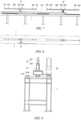
- FIG. 1 is a three-dimensional schematic structural diagram of a logistics conveying line provided according to an embodiment of the present application, in which some battery cells are placed;
- FIG. 2 is a schematic side view of a logistics conveying line provided according to an embodiment of the present application;
- FIG. 3 is a schematic front view of some components of a logistics conveying line provided according to an embodiment of the present application;
- FIG. 4 is a schematic top view of some components of a logistics conveying line provided according to an embodiment of the present application;
- FIG. 5 is a schematic front view of a logistics conveying line provided according to an embodiment of the present application, which is filled with battery cells.
- the X direction is a horizontal movement direction of a battery cell, and is also a lengthwise direction of the conveying line itself.
- the Y direction is a height direction, and is a direction in which a positioning member 3 and a driving pin 221 that will be described later are lifted or descend. Lifting means movement from bottom to top in the Y direction with reference to the direction shown in FIG. 1 , and descending means movement from top to bottom. Movement of each battery cell 5 from one station to a further station means that the battery cell 5 moves in the X direction.
- the movement of the battery cell 5 may be unidirectional, such as always moving from an upstream station to a downstream station, or may be bidirectional, for example, the battery cell can move from an upstream station to a downstream station and can also move from a downstream station to an upstream station.
- a driving mechanism 2 that drives the battery cell 5 to move reciprocates that is, the driving mechanism first moves from the station A to the station B, and can also return to the station A from the station B, to wait for a next operation.
- An embodiment of the present application provides a logistics conveying line for conveying a workpiece.
- the logistics conveying line comprises a frame 1 and a driving mechanism 2.
- the frame 1 comprises at least two stations.
- the driving mechanism 2 comprises a first driving portion 21 and connecting members 22.
- the first driving portion 21 is movably mounted to the frame 1
- the connecting members 22 are movably mounted to the first driving portion 21, and each of the connecting members 22 is further configured to switch between a connected state and a disconnected state with respect to a carrier 4.
- the carrier 4 is configured to bear a workpiece.
- the first driving portion 21 is configured to drive the carrier 4 to move from one of the stations to a further one of the stations.
- the logistics conveying line is used to conveying a workpiece.
- an object conveyed by the logistics conveying line is a carrier 4.
- the carrier 4 is, for example, a tray, and the tray is configured to bear a to-be-processed battery cell 5.
- the logistics conveying line comprises at least two stations, and at least one carrier 4 is placed at each station.
- the logistics conveying line is divided into a plurality of stations in its own lengthwise direction, that is, the X direction.
- a processing apparatus(es) is arranged on a side or two sides of the logistics conveying line in the lengthwise direction, and each processing apparatus is configured to process a workpiece at a corresponding station.
- One or more carriers 4 is/are correspondingly placed at at least one station of the logistics conveying line.
- trays may be placed at different stations on the entire conveying line, or trays may be placed at only some stations.
- FIGS. 1 to 4 schematically show that trays are placed at only some stations of the logistics conveying line, and a battery cell(s) 5 is/are placed in each tray.
- FIG. 5 schematically shows that trays are placed at all stations of the entire logistics conveying line, and a battery cell(s) 5 is/are placed in each tray.
- An existing speed chain (or belt) of the logistics conveying line may be retained or removed. If the speed chain (or belt) is retained, the speed chain (or belt) can reduce a friction force of each carrier 4 during movement of the carrier 4 relative to the speed chain (or belt), making the transfer movement of the carrier 4 smoother.
- the driving mechanism 2 is started when the carrier 4 needs to be transferred and transported.
- the driving mechanism 2 does not operate.
- the driving mechanism 2 comprises a first driving portion 21 and connecting members 22.
- the first driving portion 21 is movably mounted to the frame 1. Specifically, a movement direction of the first driving component 21 relative to the frame 1 is parallel to a workpiece conveying direction, as shown in the X direction in FIG. 1 .
- a frame 1 comprises connecting frames 12 that are arranged opposite to each other.
- the connecting frames 12 are roughly elongated, and legs 13 are provided at various positions in a lengthwise of the connecting frame 12 to support the connecting frame 12.
- the frame 1 is divided into at least two stations in the lengthwise direction of the logistics conveying line.
- One or more carriers 4 is/are placed at each of the stations.
- movement control logic adopted by the first driving portion 21 is as follows: the first driving portion 21 moves linearly from the station A to the station B, and then returns from the station B to the station A. Through the linear movement of the first driving portion 21 relative to the frame 1, a carrier 4 at the station A is conveyed to the station B. Then, the first driving portion 21 returns to the station A alone, waiting for the conveying of a next carrier 4 from the station A to the station B.
- Each connecting member 22 is further configured to switch between a connected state and a disconnected state with respect to a carrier 4.
- the first driving portion 21 is configured to drive the carrier 4 to move from one of the stations to a further one of the stations.
- connection member 22 there are a plurality of manners of connecting the connecting member 22 to the carrier 4, such as insertion, hooking, and pushing, which can implement a force between the connecting member and the carrier to bias them together during movement, so that the connecting member and the carrier are connected to each other reliably, so as to meet requirements for high-speed transfer transportation, so that the no matter how fast the driving speed of the first driving portion 21 is, the carrier 4 can be reliably transferred and transported with the connecting member 22.
- each positioning member 3 and a carrier 4 are kept in a disconnected state, while each connecting member 22 and a carrier 4 are kept in a connected state.
- the connecting member 22 can keep fixed connection with the carrier 4, so that the carrier 4 is more stably fixed to a station, thereby further improving positioning reliability of the carrier 5.
- the connecting member 22 may be kept disconnected from the carrier 4, and the positioning member 3 alone fixes the carrier 4.
- the logistics conveying line provided in the above technical solution is provided with a frame 1 and a driving mechanism 2.
- the driving mechanism 2 comprises a first driving portion 21 and connecting members 22.
- the frame 1 is fixed, the first driving portion 21 can move relative to the frame 1, and the first driving portion 21 drives the connecting members 22 to move synchronously during movement. Since each of the connecting members 22 and a carrier 4 for bearing a battery cell 5 may be kept in a connected state or may be disconnected, when the connecting member 22 and the carrier 4 are in the connected state, the movement of the connecting member 22 with the first driving portion 21 may drive the carrier 4 to move synchronously, so as to implement the movement of the battery cell 5 from one station to a further station.
- the first driving portion 21 comprises a driving member 211, the driving member 211 is movably connected to the frame 2, and the driving member 211 is connected to the connecting member 22.
- a mechanism that can finally implement linear movement is adopted as the driving member 211.
- the driving member 211 may directly output power in a linear direction, or may output rotational kinetic energy, and then a transmission mechanism is adopted to convert the rotational kinetic energy into linear kinetic energy.
- the driving member 211 comprises one of: a motor, an hydraulic cylinder, and a pneumatic cylinder.
- a servo motor/stepper motor is adopted as the driving member 211.
- the motor, the hydraulic cylinder, the pneumatic cylinder or the like is adopted as the driving member 211, which has a simple and compact structure and is controlled reliably. If the servo motor/stepper motor is adopted, displacement of the servo motor/stepper motor can be precisely controlled, thereby omitting other unnecessary limiting components and a blocking component, and further shortening the unnecessary waiting time.
- the first driving portion 21 further comprises a first matching component 213, and the driving member 211 comprises a motor; the first matching component 213 is connected to a driving shaft of the driving member 211; and the frame 1 is further provided with a second matching component 11, and the first matching component 213 is drivingly connected to the second matching component 11.
- the first matching component 213 is drivingly connected to the second matching component 11 in a manner such as gear meshing or gear-and-rack meshing, or a structure that converts kinetic energy from rotational kinetic energy to linear kinetic energy is implemented.
- a manner such as gear meshing or gear-and-rack meshing, or a structure that converts kinetic energy from rotational kinetic energy to linear kinetic energy is implemented.
- the linear kinetic energy is output, and then the first driving portion 21 moves linearly in the X direction relative to the frame 1.
- the first driving portion 21 moves in the X direction relative to the frame 1, and actually, the first driving portion 21 moves between stations.
- the first driving portion 21 itself, each connecting member 22 mounted to the first driving portion 21 and the carrier 4 connected by the connecting member 22 are moved from one station to a further station.
- the first matching component 213 and the second matching component 11 match to implement driving connection, so that the driving connection is more reliable, and the component arrangement is more convenient.
- the first matching component 213 is a gear
- the second matching component 11 comprises a rack
- the gear meshes with the rack.
- a motor is adopted as the driving member 211.
- the first matching component 213 is connected to a driving shaft of the driving member 211.
- Kinetic energy of the driving member 211 is transmitted to the gear by means of the driving shaft, and then to the rack.
- the linear kinetic energy is output, and then the first driving portion 21 moves linearly in the X direction relative to the frame 1.
- the driving member 211 is slidably connected to the frame 1, such that the driving member 211 moves linearly relative to the frame 1.
- the driving member 211 may be slidably connected to the frame 1 by means of a guide member 214.
- the guide member 214 is of multiple structures that can guide in a linear motion direction, such as a guide rail slider structure and a linear guide rail.
- the driving member 211 and the frame 1 move in a slip manner, resistance during the movement is small, and the movement is smoother.
- the driving member 211 is slidably connected to the frame 1 by means of a guide member 214; and the guide member 214 comprises a slide rail 214a and a slider 214b.
- the slide rail 214a is mounted to the frame 1.
- the slider 214b is mounted to a housing of the driving member 211.
- the slider 214b matches the slide rail 214a, such that the slider 214b moves linearly relative to the slide rail 214a.
- the slide rail 214a is fixed to the frame 1 by means of a connecting component such as bolt, or is welded to the frame 1.
- the slide rail 214a is elongated, and the length of the slide rail 214a fits with set limit displacement of the driving mechanism 2, so as to play a guiding role during the entire linear movement of the driving mechanism 2.
- the slider 214b is mounted to the housing of the driving member 211, which may be specifically by means of welding or bolted connection.
- the slide rail 214a is relatively large in size, and the slider 214b is relatively small in size.
- the slide rail 214a with a larger size is set as a fixed part, and the slider 214b is set as a component that can move linearly with the housing of the driving member 211.
- the driving member 211 has a small bearing weight during movement and requires less power, the overall size of the movable part is small, and the entire movable part has a compact and small structure and moves more stably and reliably.
- the first driving portion 21 further comprises a first supporting member 212, and the first supporting member 212 is fixedly connected to the housing of the driving member 211, to move with movement of the driving member 211; and the connecting members 22 are movably mounted to the first supporting member 212.
- Each first driving portion 21 may independently drive one connecting member 22 to act, or each first driving portion 21 may drive a plurality of connecting members 22 to act.
- the latter setting manner is taken as an example herein.
- the first supporting member 212 comprises a strip-shaped plate.
- Connecting members 22 are movably mounted to the first driving portion 21. Specifically, a movement direction of the connecting members 22 relative to the first driving portion 21 is perpendicular to the X direction, that is, in a vertical direction, that is, the Y direction in FIG. 1 .
- first supporting member 212 Through the arrangement of the first supporting member 212, a plurality of connecting members 22 are mounted to a common first supporting member 212.
- the first driving portion 21 moves linearly, to drive the first supporting member 212 to move linearly synchronously, and then drive each connecting member 22 located on the first supporting member 212 to move linearly synchronously.
- the connecting member 22 comprises driving pins 221 and a second supporting member 222, the driving pins 221 are mounted to the second supporting member 222, and the driving pins 221 are further configured to be connected to the carrier 4.
- the second supporting member 222 is an elongated plate, rod or column. Each second supporting member 222 is provided with a plurality of driving pins 221. Driving pins 221 mounted to a common second supporting member 222 are lifted or descend synchronously. A stepping cylinder is adopted as the second driving portion 23. One of a cylinder barrel and a piston rod of the stepping cylinder is mounted to the first supporting member 212, and the other one is fixedly connected to the second supporting member 222. The driving pins 221 are fixedly mounted to the second supporting member 222. The extension or retraction of the stepping cylinder may drive the second supporting member 222 to extend or retract synchronously, and then implement the extension or retraction of driving pins 221.
- each carrier 4 is provided with a recessed portion 41.
- the driving pin 221 is inserted into the recessed portion 41 of the carrier 4.
- the linear movement of the driving pin 221 with the first driving portion 21 may drive the carrier 4 to move linearly synchronously.
- the driving pin 221 retracts, the driving pin 221 moves away from the recessed portion 41 of the carrier 4, and there is no connection relationship therebetween. In this state, the linear movement of the driving pin 221 with the first driving portion 21 does not affect the position of the carrier 4 on the frame 1.
- the connecting member 22 and the carrier 4 may be kept in a connected state or a disconnected state. Since each station is mounted to a liftable positioning member 3, the positioning member 3 is also kept connected to the carrier 4. At this time, if the connecting member 22 and the carrier 4 are kept in the connected state, the positioning member 3 and the connecting member 22 jointly stably fix the carrier 4 to the current station. This fixes the carrier 4 to the current station more reliably, and the carrier 4 does not move easily during battery cell processing. At this time, if the connecting member 22 and the carrier 4 are kept in a disconnected state, the carrier 4 is still fixed to the current station because the positioning member 3 and the carrier 4 are kept in a connected state.
- the connecting member 22 moves the carrier 4 from the station A to the station B, and after the positioning member 3 is connected to the carrier 4, the connecting member 22 retracts to leave the carrier 4. Then, the driving member 211 drives the connecting member 22 to return to the station A by means of the first supporting member 212, so as to prepare for conveying a next carrier 4.
- the tray is driven by inserting the driving pins 221, so that the speed of the logistics line is increased from 18 m/min to at least 48 m/min, thereby greatly increasing the speed of moving the battery cell 5, and improving processing efficiency.
- the driving mechanism 2 further comprises second driving portions 23, wherein the second driving portions 23 are mounted to the first supporting member 212 and drivingly connected to the connecting member 22, to drive the connecting member 22 to move, such that the connecting member 22 switches between the connected state and the disconnected state with respect to the carrier 4.
- the second driving portions 23 is implemented by adopting, for example, a linear motor, a pneumatic cylinder, or a hydraulic cylinder.
- the second driving portion 23 drives the connecting member 22 to move in a direction, specifically, such as vertical lifting or descending.
- Each first supporting member 212 may be provided with a plurality of second driving portions 23.
- each first supporting member 212 is provided with two second driving portions 23.
- the two second driving portions 23 are arranged at a distance from each other in the X direction.
- the two second driving portions 23 are independent.
- the two second driving portions 23 may operate synchronously, such that all connecting members 22 located on a common first supporting member 212 are lifted or descend synchronously.
- the connecting members 22 When the connecting members 22 are lifted, the connecting members 22 each approach a carrier 4.
- the connecting member 22 is lifted in place, the connecting member 22 is connected to the carrier 4. In this state, the linear movement of the connecting member 22 may drive the carrier 4 to move linearly synchronously.
- the second driving portion 23 may be of a same structure or different structures.
- each second driving portion 23 is implemented by adopting a pneumatic cylinder, a hydraulic cylinder or another power component that directly outputs linear kinetic energy, specifically, such as a stepping cylinder.
- a pneumatic cylinder a hydraulic cylinder or another power component that directly outputs linear kinetic energy
- specifically such as a stepping cylinder.
- the above arrangement is adopted considering that a movement space of the connecting member 22 is relatively narrow, and if a power conversion mechanism is arranged, the arrangement difficulty is high, so that the structure of the logistics conveying line is too complicated.
- the control of the stepping cylinder is accurate, which can implement precise control of a lifting or descending height of the connecting member 22.
- Connecting members 22 located at a common station may be driven to lift or descend by the same second driving portion 23, or may be driven to lift or descend by two or more second driving portions 23.
- Connecting members 22 may be in a one-to-one correspondence with second driving portions 23, or a plurality of connecting members 22 may correspond to one second driving portion 23.
- the second driving portions 23 are adopted to change the positions of the connecting members 22, and then change the positions of the connecting members 22 and the carriers 4 relative to each other.
- This mechanical driving manner has high reliability, and kinetic energy transmission between components is sufficient.
- a plurality of second driving portions 23 are spaced and mounted on each first supporting member 212.
- Each second driving portion 23 corresponds to one driving pin 221, or a plurality of driving pins 221 may correspond to one second driving portion 23.
- one first supporting member 212 is adopted to drive a plurality of second driving portions 23 to move synchronously, and the second driving portions 23 drive a plurality of driving pins 221, so that the driving efficiency is high.
- the logistics conveying line further comprises positioning members 3, wherein at least one positioning member 3 is movably mounted on each of the stations, and the positioning member(s) 3 is/are configured to fix the carrier 4 to the current station.
- the logistics conveying line further comprises positioning members 3, wherein at least one positioning member 3 is movably mounted at each station, a moving direction of each positioning member 3 relative to the frame 1 is, for example, a vertical direction, that is, the positioning member 3 can be lifted or descend, and a lifting/descending direction is the Y direction.
- the positioning member 3 cannot move horizontally relative to the frame 1, that is, the positioning member 3 is fixed in the X direction and can be lifted or descend in the Y direction.
- the positioning member 3 is configured in such a manner that a carrier 4 is fixed to the station.
- the positioning member 3 is, for example, a positioning pin. Specifically, the positioning member 3 changes its position to implement the switching of the positioning member 3 between a connected state and a disconnected state with respect to the carrier 4.
- the carrier 4 is fixed to the current station.
- the positioning member 3 and the carrier 4 are in the disconnected state, the carrier 4 can be driven by the driving mechanism 2 to implement transfer transportation.
- the positioning member 3 and the carrier 4 match in the following manner: the bottom of the carrier 4 is provided with a through hole 42 (refer to FIG. 17 ), and the through hole 42 matches the positioning member 3.
- the carrier 4 is fixed to this station by the positioning member 3.
- the positioning member 3 in a retracted state leaves the through hole 42 at the bottom of the carrier 4, the carrier 4 and the positioning member 3 are in a disconnected state. In this state, the carrier 4 can be moved from one station to a further station under the driving of the driving mechanism 2 to be described later, that is, transfer transportation is implemented.
- Each carrier 4 is correspondingly provided with at least one positioning member 3. If two or more positioning pins are provided, a phenomenon such as rotation of the carrier 4 at a station can be effectively prevented, so that the carrier 4 is more reliably fixed to the station.
- Each station is provided with at least one positioning member 3, and each positioning member 3 is separately provided with a driving source to implement the lifting and descending of the positioning pin 3, so that a state of each positioning member 3 can be precisely and independently controlled.
- positioning members 3 that perform the same action may also be driven by a common driving source, and the driving source drives the positioning members 3 to act synchronously by means of a transmission mechanism. This requires a smaller number of driving sources.
- a logistics conveying system comprises a logistics conveying line provided according to any one of the technical solutions of the present application and carriers 4, wherein at least one carrier 4 is placed at each station.
- the carrier 4 is configured to bear a battery cell 5, and may be specifically a tray. One or more battery cells 5 may be placed in each tray. After being processed at one station, the battery cell 5 is moved to a next station for subsequent processing. No connecting component is provided between the battery cell 5 and the tray. Common translation of the battery cell and the tray is implemented by means of a friction force, so as to implement transfer transportation.
- transfer transportation means the movement of a carrier 4 from one station to a further station. Battery cells 5 located in one tray move synchronously. Battery cells 5 located at a same station may also move synchronously.
- the logistics conveying system provided in the above technical solution can efficiently transfer a carrier 4 between stations because the system has the logistics conveying line provided in the above technical solution.
- a bottom of each carrier 4 is provided with a recessed portion 41, and the recessed portion 41 matches a connecting member 22; the connecting member 22 in an extended state is inserted into the recessed portion 41, and the carrier 4 and the connecting member 22 are in a connected state; and the connecting member 22 in a retracted state leaves the recessed portion 41, and the carrier 4 and the connecting member 22 are in a disconnected state.
- the connecting member 22 comprises driving pins 221. After each of the driving pins 221 extends, the driving pin 221 is inserted into the recessed portion 41 of the carrier 4. In this state, the driving pin 221 drives the carrier 4 to move linearly synchronously. After the driving pin 221 retracts, that is, after the driving pin 221 moves away from the recessed portion 41 of the carrier 4, there is no connection relationship between the driving pin 221 and the carrier 4. In this state, the linear movement of the driving pin 221 with the first driving portion 21 does not affect the position of the carrier 4 on the frame 1.
- the tray is driven by insertion, so that the speed of the logistics line is increased from 18 m/min to at least 48 m/min, thereby greatly increasing the speed of moving the battery cell 5, and improving processing efficiency.
- an embodiment of the present application further provides a logistics conveying method, which is implemented by adopting a logistics conveying system provided according to any one of the above embodiments of the present application.
- the method comprises the following steps.
- step S100 connecting members 22 located at a common station are driven to extend, such that each of the connecting members 22 is inserted into a carrier 4 corresponding to the connecting member 22, to keep the connecting member 22 and the carrier 4 in a connected state.
- step S200 a first driving portion 21 is driven to drive both the connecting member 22 and the carrier 4 connected to the connecting member 22 to move from the current station to a further station.
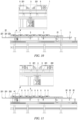
- FIGS. 10 to 18 taking an example in which a carrier 4 located at the most upstream is at a station A, in order to facilitate the comparative description of a displacement process of each battery cell 5, one driving pin 221 is used as a reference in FIGS. 10 to 17 to mark a station where the carrier 4 is located. It should be noted that due to the limitation of a view direction, positions of some components are not marked in FIGS. 10 to 18 . In this case, reference may be further made to the marked positions of the components in FIGS. 1 to 9 above. Referring to FIG. 10 , when each battery cell 5 at a station A is in a processing state, the carrier 4 is fixed by a positioning member 3.
- the positioning member 3 is in a lifted state, and the positioning member 3 is inserted into a through hole 42 at the bottom of the carrier 4.
- a driving pin 221 is in a retracted (or descending) state, and the driving pin 221 is far away from a recessed portion 41 at the bottom of the carrier 4.
- the driving pin 221 is disconnected from the carrier 4.
- the battery cell 5 After being processed at the station A, the battery cell 5 needs to be moved to a station B. Then, the logistics conveying method is adopted to implement the displacement of the battery cell 5, that is, steps S100 and S200 are performed.
- step S 100 the following operations are performed at the station A: the positioning member 3 is kept in the previous lifted state, and then the connecting member 22 is lifted. Referring to FIG. 11 , after the connecting member 22 is lifted in place, the connecting member 22 is inserted into the recessed portion 41 at the bottom of the carrier 4, and the positioning member 3 is inserted into the through hole 42 at the bottom of the carrier 4.
- the positioning member 3 is retracted, such that the positioning member 3 leaves the through hole 42 at the bottom of the carrier 4. After the positioning member 3 leaves the carrier 4, only the driving pin 221 and the carrier 4 are kept in a connected state.
- a first driving portion 21 is a component that provides linear power. After the first driving portion 21 is started, the first driving portion 21 moves in a direction from the station A to the station B relative to the frame 1. Because the connecting member 22 is connected to the first driving portion 21 by means of a second driving portion 23, the linear movement of the first driving portion 21 relative to the frame 1 may drive the connecting member 22 to move linearly synchronously. The connecting member 22 is kept connected to the carrier 4, so that the carrier 4 also moves with the linear movement of the first driving portion 21, thereby implementing the movement of the carrier 4 from the station A to the station B. It should be noted that the station B and the station A are different, and there is no upstream-downstream relationship therebetween. However, during production of the battery cell 5, the station B may be located downstream of the station A, and may be an adjacent station downstream, or may be another nonadjacent station downstream.
- FIG. 13 shows a schematic diagram showing the movement of the carrier 4 to an intermediate position A'.
- the intermediate position A' is located between the station A and the station B.
- the carrier stops at the station B.
- the driving pin 221 and the positioning member 3 are kept in a connected state, and the positioning member 3 located at the station B is far away from the carrier 4.
- the second driving portion 23 is drivingly connected to the connecting member 22.
- the connecting member 22 comprises driving pins 221 and a second supporting member 222.
- a stepping cylinder is adopted as the second driving portion 23.
- the connecting member 22 can be extended.
- the carrier 4 does not need to be moved, and the connecting member 22 is automatically inserted into the recessed portion 41 of the carrier 4 after being lifted.
- the positioning of the carrier 4 on the frame 1 can be implemented by adopting another positioning mechanism, or by adopting the existing technology, which will not be described in detail herein.
- the driving pin 22 is used to drive the carrier 4 during transfer transportation, so that reliable mechanical fixation between the driving pin 22 and the carrier 4 exists, the movement is reliable, and the speed is very fast.
- a movement amount of the driving pin 22 is controlled by a servo motor, so that precise movement can also be implemented provided that the speed is very high.
- the logistics conveying method further comprises the following steps.
- step S300 a positioning member 3 located at the further station is driven to extend to fix the carrier 4 to the further station.
- step S400 at the further station, the connecting member 22 is retracted to disconnect the connecting member 22 from the carrier 4.
- step S500 the first driving portion 21 is driven to return, to drive the connecting member 22 to return to the original station from the further station.
- step S300 referring to FIG. 15 , the positioning member 3 at the station B is lifted, so that the positioning member 3 at the station B is inserted into the through hole 42 at the bottom of the carrier 4. At this time, the positioning member 3 and the driving pin 221 at the station B are both kept connected to the carrier 4.
- step S400 at the station B, the driving pin 221 is retracted, to move away from the carrier 4 at the station B.
- step S500 referring to FIG. 16 , since the movement of the carrier 4 from the station A to the station B has been completed, the driving pin 221 has been disconnected from the carrier 4 at the station B. Then, the driving motor 211 is started again to drive the driving pin 221 back to the station A to wait for a next operation.
- the carrier 4 can be stably and reliably positioned at both the station A and the station B without separately providing a blocking mechanism, a jacking mechanism, and the like, and an operating time, an action time and a signal interaction time required for actions of these mechanisms are also omitted, so that jacking positioning is no longer needed, unnecessary time investment is reduced, and the processing efficiency is further improved.
- each station is provided with a positioning member 3, and during processing by other actuators, the driving mechanism 2 can implement action interaction of returning and inserting the tray and the positioning member 3, that is, an action of inserting the positioning member 3 into the carrier 4 and an action of disconnecting the connecting member 22 from the carrier 4 can be performed simultaneously, and an action of disconnecting the positioning member 3 from the carrier 4 and an action of inserting the connecting member 22 into the carrier 4 can also be performed simultaneously.
- the driving mechanism 2 can immediately move to a next station and continue the processing. The entire process takes a very short time, almost no time is wasted, and the production efficiency is very high.
Landscapes
- Engineering & Computer Science (AREA)
- Mechanical Engineering (AREA)
- Non-Mechanical Conveyors (AREA)
- Reciprocating Conveyors (AREA)
- Warehouses Or Storage Devices (AREA)
Abstract
Description
- This application is based on and claims priority to
Chinese patent application no. 202111158300.9 filed on September 30, 2021 - The present application relates to the field of battery processing, and in particular, to a logistics conveying line, a logistics conveying system, and a logistics conveying method.
- With the vigorous development of new energy technology, application fields of the new energy technology are becoming increasingly extensive. Battery technology is an important factor related to the development of the new energy technology. A battery comprises battery cells. Processing of the battery cells involves a plurality of different processes, and the processes are completed at different stations. In order to complete the processing of the battery cells, the battery cells often need to be moved from one station to a further station.
- During the processing of the battery cells, a time for movement between stations may directly affect production efficiency of the battery cell. If a long time is required for movement of the battery cells between stations, the production efficiency of the battery cell is low.
- In view of the above problems, the present application proposes a logistics conveying line, a logistics conveying system, and a logistics conveying method, to improve production efficiency of a battery cell.
- According to an aspect, an embodiment of the present application provides a logistics conveying line for conveying a workpiece, comprising:
- a frame comprising at least two stations; and
- a driving mechanism comprising a first driving portion and connecting members, wherein the first driving portion is movably mounted to the frame, the connecting members are movably mounted to the first driving portion, and each of the connecting members is further configured to switch between a connected state and a disconnected state with respect to a carrier; and the carrier is configured to bear a workpiece,
- wherein when the connecting member and the carrier are in the connected state, the first driving portion is configured to drive the carrier to move from one of the stations to a further one of the stations.
- The logistics conveying line provided in the above technical solution is provided with a frame and a driving mechanism. The driving mechanism comprises a first driving portion and connecting members. The frame is fixed, the first driving portion can move relative to the frame, and the first driving portion drives the connecting members to move synchronously during movement. Since each of the connecting members and a carrier for bearing a battery cell may be kept in a connected state or a disconnected state, when the connecting member and the carrier are in the connected state, the movement of the connecting member with the first driving portion may drive the carrier to move synchronously, so as to implement the movement of the battery cell from one station to a further station. When the connecting member and the carrier are in a disconnected state, the movement of the connecting member with the first driving portion does not drive the carrier to move synchronously, so that both the connecting member and the first driving portion can return to an original position. In the above technical solution, when the connecting member and the carrier are in the connected state, the connecting member and the carrier are in contact with each other, and there is a force acting therebetween biasing them together, so that no matter how fast a moving speed of the connecting member is, the carrier can be driven to move synchronously. This greatly increases the speed of moving the battery cell from one station to a further station, and improves the production efficiency of the battery cell.
- In some embodiments, the first driving portion comprises:
a driving member, wherein the driving member is movably connected to the frame, and the driving member is connected to the connecting member. - In the above technical solution, the driving member is adopted to implement the linear movement of the connecting member relative to the frame, there are a plurality of optional manners of implementing the driving member, the driving is reliable, and the driving efficiency is high.
- In some embodiments, the driving member comprises one of: a motor, an hydraulic cylinder, and a pneumatic cylinder.
- In the above technical solution, the motor, the hydraulic cylinder or the pneumatic cylinder is adopted as the driving member. On the one hand, these components are mature in technology and high in control precision; and on the other hand, a rotation speed of the motor and expansion/contraction speeds of the hydraulic cylinder and the pneumatic cylinder are all very fast, which is beneficial to the rapid transfer transportation of the carrier.
- In some embodiments, the first driving portion further comprises a first matching component, and the driving member comprises a motor; the first matching component is connected to a driving shaft of the driving member; and the frame is further provided with a second matching component, and the first matching component is drivingly connected to the second matching component.
- There are a plurality of ways of implementing the first matching component and the second matching component. If the driving member directly outputs linear power, the first matching component and the second matching component no longer need to switch a power direction; and if the driving member outputs rotational power, kinetic energy conversion is implemented by means of the first matching component and the second matching component.
- In some embodiments, the first matching component comprises a gear, and the second matching component comprises a rack; and the gear meshes with the rack. The matching of the gear and the rack is adopted to implement kinetic energy transmission, the transmission is reliable, and the energy utilization efficiency is high. A space required for mounting the gear and the rack is small, which is conducive to optimizing the structure of the logistics conveying line.
- In some embodiments, the driving member is slidably connected to the frame, such that the driving member moves linearly relative to the frame. A sliding manner is adopted to implement linear movement, and resistance during the movement is small.
- In some embodiments, the driving member is slidably connected to the frame by means of a guide member; the guide member comprises:
- a slide rail mounted to the frame; and
- a slider mounted to a housing of the driving member; and the slider matches the slide rail, such that the slider moves linearly relative to the slide rail.
- In the above technical solution, the slide rail with a larger size is set as a fixed part, and the slider is set as a component that can move linearly with the housing of the driving member. With this arrangement, the driving member has a small bearing weight during movement and requires less power, the overall size of the movable part is small, and the entire movable part has a compact and small structure and moves more stably and reliably.
- In some embodiments, the first driving portion further comprises a first supporting member, and the first supporting member is fixedly connected to the housing of the driving member, to move with movement of the driving member; and the connecting member is movably mounted to the first supporting member. In the above technical solution, through the arrangement of the first supporting member, a plurality of connecting members can be mounted to a common first supporting member. The first driving portion moves linearly, to drive the first supporting member to move linearly synchronously, and then drive each connecting member located on the first supporting member to move linearly synchronously.
- In some embodiments, the connecting member comprises driving pins and a second supporting member, the driving pins are mounted to the second supporting member, and the driving pins are configured to be connected to the carrier. In the above technical solution, the carrier is driven by inserting the driving pin, so that a speed of transporting the carrier by means of the logistics line can be increased by nearly three times, thereby greatly increasing the speed of moving the battery cell, and improving processing efficiency.
- In some embodiments, the driving mechanism further comprises:
second driving portions each mounted to the first supporting member and drivingly connected to the connecting member, to drive the connecting member to move, such that the connecting member switches between the connected state and the disconnected state with respect to the carrier. - In the above technical solution, the second driving portions are adopted to change the position of the connecting members, and then change the positions of the connecting members and the carriers relative to each other. This mechanical driving manner has high reliability, and kinetic energy transmission between components is sufficient.
- In some embodiments, a plurality of second driving portions are spaced and mounted on each first supporting member. In the above technical solution, one first supporting member is adopted to drive a plurality of second driving portions to move synchronously, and the second driving portions drive a plurality of driving pins, so that the driving efficiency is high.
- In some embodiments, the logistics conveying line further comprises: positioning members, wherein at least one positioning member is movably mounted on each of the stations, and the positioning member(s) is/are configured to fix the carrier to the current station. In the above technical solution, the positioning member fixes the carrier to the station where the positioning member is located, to facilitate the processing of a battery cell in the carrier.
- An embodiment of the present application further provides a logistics conveying system, comprising:
- a logistics conveying line provided in any one of the technical solutions of the present application; and
- carriers, wherein at least one carrier is placed at each station.
- The logistics conveying system provided in the above technical solution also has the advantages described above because the system has the logistics conveying line described in the above technical solution.
- In some embodiments, a bottom of each carrier is provided with a recessed portion, and the recessed portion matches a connecting member; the connecting member in an extended state is inserted into the recessed portion, and the carrier and the connecting member are in a connected state; and the connecting member in a retracted state leaves the recessed portion, and the carrier and the connecting member are in a disconnected state. The recessed portions are adopted to implement the fixed connection between the connecting members and the carriers, so that an abutting force exists therebetween, and the kinetic energy transmission is more reliable, thereby better meeting requirements for transportation at a faster speed.
- An embodiment of the present application further provides a logistics conveying method, comprising the following steps:
- driving connecting members located at a common station to extend, such that each of the connecting members is inserted into a carrier corresponding to the connecting member, to keep the connecting member and the carrier in a connected state; and
- driving a first driving portion to drive both the connecting member and the carrier connected to the connecting member to move from the current station to a further downstream station.
- In the logistics conveying method provided in the above technical solution, throughout the transfer transportation of the carrier, a connection relationship between the carrier and at least one of the positioning member and the connecting member is kept. In this way, the carrier is always limited, thereby preventing the carrier from being subjected to slip, deviation caused by touch, and the like. In addition, reliable mechanical fixation between the connecting member and the carrier exists, the movement is reliable, and the speed is very fast.
- In some embodiments, the logistics conveying method further comprises the following steps:
- driving a positioning member located at the further station to extend to fix the carrier to the further station;
- at the further station, retracting the connecting member to disconnect the connecting member from the carrier; and
- driving the first driving portion to return, to drive the connecting member to return to the upstream station from the further station.
- In the above technical solution, there is no need to separately provide a blocking mechanism, a jacking mechanism, and the like, and an operating time, an action time and a signal interaction time required for actions of these mechanisms are also omitted, so that jacking positioning is no longer needed, unnecessary time investment is reduced, and the processing efficiency is further improved. In addition, each station is provided with a positioning member, and during processing by other actuators, the driving mechanism can implement action interaction of returning and inserting the tray and the positioning member, that is, an action of inserting the positioning member into the carrier and an action of disconnecting the connecting member from the carrier can be performed simultaneously, and an action of disconnecting the positioning member from the carrier and an action of inserting the connecting member into the carrier can also be performed simultaneously. When other actuators finish the processing, the driving mechanism can immediately move to a next station and continue the processing. The entire process takes a very short time, almost no time is wasted, and the production efficiency is high.
- The above description is only an overview of the technical solutions of the present application. In order to more clearly understand the technical means of the present application to implement same according to the contents of the description, and in order to make the above and other objectives, features and advantages of the present application more obvious and understandable, specific implementations of the present application are exemplarily described below.
- Various other advantages and benefits will become apparent to those of ordinary skill in the art upon reading the following detailed description of preferred implementations. The accompanying drawings are merely for the purpose of illustrating the preferred implementations and are not to be construed as limiting the present application. Moreover, like components are denoted by like reference numerals throughout the accompanying drawings. In the accompanying drawings:
-
FIG. 1 is a three-dimensional schematic structural diagram of a logistics conveying line provided according to an embodiment of the present application, in which some battery cells are placed; -
FIG. 2 is a schematic side view of a logistics conveying line provided according to an embodiment of the present application; -
FIG. 3 is a schematic front view of some components of a logistics conveying line provided according to an embodiment of the present application; -
FIG. 4 is a schematic top view of some components of a logistics conveying line provided according to an embodiment of the present application; -
FIG. 5 is a schematic front view of a logistics conveying line provided according to an embodiment of the present application, which is filled with battery cells; -
FIG. 6 is a three-dimensional schematic diagram of a driving mechanism of a logistics conveying line provided according to an embodiment of the present application; -
FIG. 7 is a schematic front view of a driving mechanism of a logistics conveying line provided according to an embodiment of the present application; -
FIG. 8 is a schematic top view of a driving mechanism of a logistics conveying line provided according to an embodiment of the present application; -
FIG. 9 is a schematic side view of a driving mechanism of a logistics conveying line provided according to an embodiment of the present application; -
FIG. 10 is a schematic diagram showing connection between a positioning member and a carrier at a station during conveying of battery cells by using a logistics conveying line provided according to an embodiment of the present application; -
FIG. 11 is a schematic diagram showing connection between a carrier and both a driving pin and a positioning member at a station during conveying of battery cells by using a logistics conveying line provided according to an embodiment of the present application; -
FIG. 12 is a schematic diagram showing connection between a driving pin and a carrier during conveying of battery cells by using a logistics conveying line provided according to an embodiment of the present application; -
FIG. 13 is a schematic diagram showing a connection relationship between a driving pin and a carrier during conveying of battery cells by using a logistics conveying line provided according to an embodiment of the present application; -
FIG. 14 is a schematic diagram showing the conveying of a battery cell to a next station by using a logistics conveying line provided according to an embodiment of the present application; -
FIG. 15 is a schematic diagram showing connection between a positioning member and a carrier at a next station after a battery cell is conveyed to the next station by using a logistics conveying line provided according to an embodiment of the present application; -
FIG. 16 is a schematic diagram showing disconnection of a driving pin from a carrier after a battery cell is conveyed to a next station by using a logistics conveying line provided according to an embodiment of the present application; -
FIG. 17 is a three-dimensional schematic structural diagram of a carrier of a logistics conveying system provided according to an embodiment of the present application; and -
FIG. 18 is a schematic flow chart of a logistics conveying method provided according to an embodiment of the present application. - Reference numerals in the specific implementations:
-
Frame 1,driving mechanism 2,positioning member 3,carrier 4, andbattery cell 5; -
rack 11, connectingframe 12, and leg 13; - first driving
portion 21, connectingmember 22, second drivingportion 23, and second supporting member 24; - driving
motor 211, first supportingmember 212,gear 213, and guidemember 214; -
slide rail 214a, andslider 214b; - driving
pin 221, and second supportingmember 222; - recessed
portion 41, and throughhole 42. - Embodiments of the technical solutions of the present application will be described in more detail below with reference to the drawings. The following embodiments are merely intended to more clearly illustrate the technical solutions of the present application, so they merely serve as examples, but are not intended to limit the scope of protection of the present application.
- Unless otherwise defined, all technical and scientific terms used herein have the same meanings as those commonly understood by those skilled in the art to which the present application belongs. The terms used herein are merely for the purpose of describing specific embodiments, but are not intended to limit the present application. The terms "comprising" and "having" and any variations thereof in the description and the claims of the present application as well as the brief description of the drawings described above are intended to cover non-exclusive inclusion.
- In the description of the embodiments of the present application, the technical terms "first", "second", etc. are merely used for distinguishing different objects, and are not to be construed as indicating or implying relative importance or implicitly indicating the number, particular order or primary-secondary relationship of the technical features modified thereby. In the description of the embodiments of the present application, the phrase "a plurality of" means two or more, unless otherwise explicitly and specifically defined.
- The phrase "embodiment" mentioned herein means that the specific features, structures, or characteristics described in conjunction with the embodiment can be encompassed in at least one embodiment of the present application. The phrase at various locations in the description does not necessarily refer to the same embodiment, or an independent or alternative embodiment exclusive of another embodiment. Those skilled in the art understand explicitly or implicitly that the embodiment described herein may be combined with another embodiment.
- In the description of the embodiments of the present application, the term "and/or" is merely intended to describe the associated relationship of associated objects, indicating that three relationships may exist, for example, A and/or B may indicate: the following three cases: only A exists, both A and B exist, and only B exists. In addition, the character "/" herein generally indicates an "or" relationship between the associated objects.
- In the description of the embodiments of the present application, the term "a plurality of" means two or more (including two), similarly the term "a plurality of groups" means two or more groups (including two groups), and the term "a plurality of pieces" means two or more pieces (including two pieces).
- In the description of the embodiments of the present application, the orientation or position relationship indicated by the technical terms "central", "longitudinal", "transverse", "length", "width", "thickness", "upper", "lower", "front", "rear", "left", "right", "vertical", "horizontal", "top", "bottom", "inner", "outer", "clockwise", "counterclockwise", "axial", "radial", "circumferential", etc. are based on the orientation or position relationship shown in the drawings and are merely intended to facilitate and simplify the description of the embodiments of the present application, rather than indicating or implying that the device or element considered must have a particular orientation or be constructed and operated in a particular orientation, and therefore not to be construed as limiting the embodiments of the present application.
- In the description of the embodiments of the present application, unless otherwise explicitly specified and defined, the technical terms "mounting", "connected", "connection", "fixing", etc. should be understood in a broad sense, for example, they may be a fixed connection, a detachable connection, or an integrated connection; may be a mechanical connection or an electrical connection; and may be a direct connection or an indirect connection by means of an intermediate medium, or internal communication between two elements or interaction relationship between two elements. For those of ordinary skill in the art, the specific meanings of the above terms in the embodiments of the present application can be understood according to specific situations.
- In a related technology, a logistics conveying line is adopted to move battery cells between stations to complete different battery cell processes. The logistics conveying line comprises a speed chain (or belt), and the speed chain (or belt) is driven to move. A battery cell is placed in a tray. The tray is directly placed on the speed chain (or belt), and a friction force between the speed chain (or belt) and the tray is used to move the tray with the speed chain (or belt), so that the tray moves from one station to a further station, and the battery cell moves with the tray from one station to a further station to complete different processes.
- The applicant has found that there are at least the following problems in the related technology: the conveying line uses the friction force to convey the tray loaded with the battery cell, and the friction force between the conveying line and the tray is small, so that the tray transport speed cannot be too fast. If the speed is too fast, the tray may slip, so that the tray cannot be transported. This limits production efficiency of the battery cell.
- The applicant has found through research that, in the related technology, the friction force between the tray and the speed chain (or belt) is used for conveying the battery cell, and the maximum speed of the conveying line can only reach 18 m/min. It is difficult to increase the battery cell conveying speed without changing a stress manner during battery cell conveying. If the stress manner of the battery cell is increased, normal processes of the battery cell may be affected. Therefore, through creative labor and research, the applicant has provided a technical solution in which during conveying of a battery cell, the battery cell is kept connected to a carrier bearing the battery cell, but the battery cell can be far away from the carrier of the battery cell during normal processing of the battery cell. In this technical solution, because the stress manner of the battery cell during transfer transportation is changed, and a contact manner is adopted to drive the battery cell to be transferred and transported with the carrier, the battery cell can be reliably transported without slipping no matter how fast the transfer transportation speed is. In addition, normal processing of the battery cell is not affected.
- A logistics conveying line disclosed in an embodiment of the present application is used for processing and production of a battery cell and a component with similar production links. The battery cell can be used in, but not limited to, a power consuming device such as a vehicle, a ship or an aircraft. The power consuming device may be, but is not limited to, a mobile phone, a tablet, a notebook computer, an electric toy, a power tool, a battery cart, an electric vehicle, a ship, a spacecraft, etc. The electric toy may include a stationary or mobile electric toy, such as a game console, an electric vehicle toy, an electric ship toy, and an electric airplane toy. The spacecraft may include an airplane, a rocket, a space shuttle, a spaceship, etc.
- The technical solution provided in the present application will be explained in more detail below with reference to
FIGS. 1 to 18 . - Referring to
FIGS. 1 to 5 ,FIG. 1 is a three-dimensional schematic structural diagram of a logistics conveying line provided according to an embodiment of the present application, in which some battery cells are placed;FIG. 2 is a schematic side view of a logistics conveying line provided according to an embodiment of the present application;FIG. 3 is a schematic front view of some components of a logistics conveying line provided according to an embodiment of the present application;FIG. 4 is a schematic top view of some components of a logistics conveying line provided according to an embodiment of the present application; andFIG. 5 is a schematic front view of a logistics conveying line provided according to an embodiment of the present application, which is filled with battery cells. - In order to clearly describe each direction in the following embodiments, in
FIG. 1 , an X direction and a Y direction are marked. The X direction is a horizontal movement direction of a battery cell, and is also a lengthwise direction of the conveying line itself. The Y direction is a height direction, and is a direction in which apositioning member 3 and adriving pin 221 that will be described later are lifted or descend. Lifting means movement from bottom to top in the Y direction with reference to the direction shown inFIG. 1 , and descending means movement from top to bottom. Movement of eachbattery cell 5 from one station to a further station means that thebattery cell 5 moves in the X direction. The movement of thebattery cell 5 may be unidirectional, such as always moving from an upstream station to a downstream station, or may be bidirectional, for example, the battery cell can move from an upstream station to a downstream station and can also move from a downstream station to an upstream station. In order to clearly describe the technical solutions of the embodiments of the present application, the following takes an example in which eachbattery cell 5 moves from an upstream station to a downstream station, specifically from a station A to a station B.A driving mechanism 2 that drives thebattery cell 5 to move reciprocates, that is, the driving mechanism first moves from the station A to the station B, and can also return to the station A from the station B, to wait for a next operation. - An embodiment of the present application provides a logistics conveying line for conveying a workpiece. The logistics conveying line comprises a
frame 1 and adriving mechanism 2. Theframe 1 comprises at least two stations. Thedriving mechanism 2 comprises afirst driving portion 21 and connectingmembers 22. Thefirst driving portion 21 is movably mounted to theframe 1, the connectingmembers 22 are movably mounted to the first drivingportion 21, and each of the connectingmembers 22 is further configured to switch between a connected state and a disconnected state with respect to acarrier 4. Thecarrier 4 is configured to bear a workpiece. When the connectingmember 22 and thecarrier 4 are in the connected state, the first drivingportion 21 is configured to drive thecarrier 4 to move from one of the stations to a further one of the stations. - The logistics conveying line is used to conveying a workpiece. In the field of battery cell processing, an object conveyed by the logistics conveying line is a
carrier 4. Thecarrier 4 is, for example, a tray, and the tray is configured to bear a to-be-processed battery cell 5. - The logistics conveying line comprises at least two stations, and at least one
carrier 4 is placed at each station. Specifically, the logistics conveying line is divided into a plurality of stations in its own lengthwise direction, that is, the X direction. A processing apparatus(es) is arranged on a side or two sides of the logistics conveying line in the lengthwise direction, and each processing apparatus is configured to process a workpiece at a corresponding station. - One or
more carriers 4 is/are correspondingly placed at at least one station of the logistics conveying line. Specifically, trays may be placed at different stations on the entire conveying line, or trays may be placed at only some stations. For example,FIGS. 1 to 4 schematically show that trays are placed at only some stations of the logistics conveying line, and a battery cell(s) 5 is/are placed in each tray.FIG. 5 schematically shows that trays are placed at all stations of the entire logistics conveying line, and a battery cell(s) 5 is/are placed in each tray. - An existing speed chain (or belt) of the logistics conveying line may be retained or removed. If the speed chain (or belt) is retained, the speed chain (or belt) can reduce a friction force of each
carrier 4 during movement of thecarrier 4 relative to the speed chain (or belt), making the transfer movement of thecarrier 4 smoother. - The
driving mechanism 2 is started when thecarrier 4 needs to be transferred and transported. When thebattery cell 5 in thecarrier 4 does need to be transferred and transported, for example, when the battery cell is being processed, thedriving mechanism 2 does not operate. As described above, thedriving mechanism 2 comprises afirst driving portion 21 and connectingmembers 22. Thefirst driving portion 21 is movably mounted to theframe 1. Specifically, a movement direction of thefirst driving component 21 relative to theframe 1 is parallel to a workpiece conveying direction, as shown in the X direction inFIG. 1 . - Refer to
FIGS. 1 to 9 , especiallyFIGS. 6 to 9 . Aframe 1 comprises connectingframes 12 that are arranged opposite to each other. The connecting frames 12 are roughly elongated, and legs 13 are provided at various positions in a lengthwise of the connectingframe 12 to support the connectingframe 12. As shown inFIG. 1 , theframe 1 is divided into at least two stations in the lengthwise direction of the logistics conveying line. One ormore carriers 4 is/are placed at each of the stations. - In some embodiments of the present application, movement control logic adopted by the first driving
portion 21 is as follows: the first drivingportion 21 moves linearly from the station A to the station B, and then returns from the station B to the station A. Through the linear movement of the first drivingportion 21 relative to theframe 1, acarrier 4 at the station A is conveyed to the station B. Then, the first drivingportion 21 returns to the station A alone, waiting for the conveying of anext carrier 4 from the station A to the station B. - Each connecting
member 22 is further configured to switch between a connected state and a disconnected state with respect to acarrier 4. When the connectingmember 22 and thecarrier 4 are in the connected state, the first drivingportion 21 is configured to drive thecarrier 4 to move from one of the stations to a further one of the stations. - There are a plurality of manners of connecting the connecting
member 22 to thecarrier 4, such as insertion, hooking, and pushing, which can implement a force between the connecting member and the carrier to bias them together during movement, so that the connecting member and the carrier are connected to each other reliably, so as to meet requirements for high-speed transfer transportation, so that the no matter how fast the driving speed of the first drivingportion 21 is, thecarrier 4 can be reliably transferred and transported with the connectingmember 22. - During transfer transportation, each positioning
member 3 and acarrier 4 are kept in a disconnected state, while each connectingmember 22 and acarrier 4 are kept in a connected state. However, during processing of thebattery cell 5, the connectingmember 22 can keep fixed connection with thecarrier 4, so that thecarrier 4 is more stably fixed to a station, thereby further improving positioning reliability of thecarrier 5. Certainly, during the processing of thebattery cell 5, the connectingmember 22 may be kept disconnected from thecarrier 4, and thepositioning member 3 alone fixes thecarrier 4. - The logistics conveying line provided in the above technical solution is provided with a
frame 1 and adriving mechanism 2. Thedriving mechanism 2 comprises afirst driving portion 21 and connectingmembers 22. Theframe 1 is fixed, the first drivingportion 21 can move relative to theframe 1, and the first drivingportion 21 drives the connectingmembers 22 to move synchronously during movement. Since each of the connectingmembers 22 and acarrier 4 for bearing abattery cell 5 may be kept in a connected state or may be disconnected, when the connectingmember 22 and thecarrier 4 are in the connected state, the movement of the connectingmember 22 with the first drivingportion 21 may drive thecarrier 4 to move synchronously, so as to implement the movement of thebattery cell 5 from one station to a further station. When the connectingmember 22 and thecarrier 4 are in a disconnected state, the movement of the connectingmember 22 with the first drivingportion 21 does not drive thecarrier 4 to move synchronously, so that both the connectingmember 22 and the first drivingportion 21 can return to an original position. In the above technical solution, when the connectingmember 22 and thecarrier 4 are in the connected state, the connecting member and the carrier are in contact with each other, and there is a force acting therebetween to bias them together, so that no matter how fast a moving speed of the connectingmember 22 is, thecarrier 4 can be driven to move synchronously. This greatly increases the speed of moving thebattery cell 5 from one station to a further station, and improves the production efficiency of thebattery cell 5. - According to some embodiments of the present application, optionally, referring to
FIGS. 1 to 9 , in some embodiments, the first drivingportion 21 comprises a drivingmember 211, the drivingmember 211 is movably connected to theframe 2, and the drivingmember 211 is connected to the connectingmember 22. - A mechanism that can finally implement linear movement is adopted as the driving
member 211. Specifically, for example, the drivingmember 211 may directly output power in a linear direction, or may output rotational kinetic energy, and then a transmission mechanism is adopted to convert the rotational kinetic energy into linear kinetic energy. - In the above technical solution, there are a plurality of forms of implementing the driving
member 211, which can implement stable and rapid transfer transportation of thebattery cell 5. - According to some embodiments of the present application, optionally, still referring to
FIGS. 1 to 9 , in some embodiments, the drivingmember 211 comprises one of: a motor, an hydraulic cylinder, and a pneumatic cylinder. - In some embodiments, a servo motor/stepper motor is adopted as the driving
member 211. - The motor, the hydraulic cylinder, the pneumatic cylinder or the like is adopted as the driving
member 211, which has a simple and compact structure and is controlled reliably. If the servo motor/stepper motor is adopted, displacement of the servo motor/stepper motor can be precisely controlled, thereby omitting other unnecessary limiting components and a blocking component, and further shortening the unnecessary waiting time. - According to some embodiments of the present application, optionally, still referring to
FIGS. 1 to 9 , in some embodiments, the first drivingportion 21 further comprises afirst matching component 213, and the drivingmember 211 comprises a motor; thefirst matching component 213 is connected to a driving shaft of the drivingmember 211; and theframe 1 is further provided with asecond matching component 11, and thefirst matching component 213 is drivingly connected to thesecond matching component 11. - The
first matching component 213 is drivingly connected to thesecond matching component 11 in a manner such as gear meshing or gear-and-rack meshing, or a structure that converts kinetic energy from rotational kinetic energy to linear kinetic energy is implemented. Through the matching of thefirst matching component 213 and thesecond matching component 11, the linear kinetic energy is output, and then the first drivingportion 21 moves linearly in the X direction relative to theframe 1. - As described above, there are a plurality of stations provided through division in the lengthwise direction of the
frame 1. Thefirst driving portion 21 moves in the X direction relative to theframe 1, and actually, the first drivingportion 21 moves between stations. Through the movement of the first drivingportion 21, the first drivingportion 21 itself, each connectingmember 22 mounted to the first drivingportion 21 and thecarrier 4 connected by the connectingmember 22 are moved from one station to a further station. In the above technical solution, thefirst matching component 213 and thesecond matching component 11 match to implement driving connection, so that the driving connection is more reliable, and the component arrangement is more convenient. - According to some embodiments of the present application, optionally, the
first matching component 213 is a gear, thesecond matching component 11 comprises a rack, and the gear meshes with the rack. - As described above, a motor is adopted as the driving
member 211. Thefirst matching component 213 is connected to a driving shaft of the drivingmember 211. Kinetic energy of the drivingmember 211 is transmitted to the gear by means of the driving shaft, and then to the rack. - Through the matching of the gear and the rack, the linear kinetic energy is output, and then the first driving
portion 21 moves linearly in the X direction relative to theframe 1. - According to some embodiments of the present application, optionally, the driving
member 211 is slidably connected to theframe 1, such that the drivingmember 211 moves linearly relative to theframe 1. - Specifically, the driving
member 211 may be slidably connected to theframe 1 by means of aguide member 214. Theguide member 214 is of multiple structures that can guide in a linear motion direction, such as a guide rail slider structure and a linear guide rail. - The driving
member 211 and theframe 1 move in a slip manner, resistance during the movement is small, and the movement is smoother. - According to some embodiments of the present application, optionally, in some embodiments, the driving
member 211 is slidably connected to theframe 1 by means of aguide member 214; and theguide member 214 comprises aslide rail 214a and aslider 214b. Theslide rail 214a is mounted to theframe 1. Theslider 214b is mounted to a housing of the drivingmember 211. Theslider 214b matches theslide rail 214a, such that theslider 214b moves linearly relative to theslide rail 214a. - For the
slide rail 214a, specifically, for example, theslide rail 214a is fixed to theframe 1 by means of a connecting component such as bolt, or is welded to theframe 1. Theslide rail 214a is elongated, and the length of theslide rail 214a fits with set limit displacement of thedriving mechanism 2, so as to play a guiding role during the entire linear movement of thedriving mechanism 2. Theslider 214b is mounted to the housing of the drivingmember 211, which may be specifically by means of welding or bolted connection. - The
slide rail 214a is relatively large in size, and theslider 214b is relatively small in size. In the above technical solution, theslide rail 214a with a larger size is set as a fixed part, and theslider 214b is set as a component that can move linearly with the housing of the drivingmember 211. With this arrangement, the drivingmember 211 has a small bearing weight during movement and requires less power, the overall size of the movable part is small, and the entire movable part has a compact and small structure and moves more stably and reliably. - According to some embodiments of the present application, optionally, the first driving
portion 21 further comprises a first supportingmember 212, and the first supportingmember 212 is fixedly connected to the housing of the drivingmember 211, to move with movement of the drivingmember 211; and the connectingmembers 22 are movably mounted to the first supportingmember 212. - Each first driving
portion 21 may independently drive one connectingmember 22 to act, or each first drivingportion 21 may drive a plurality of connectingmembers 22 to act. The latter setting manner is taken as an example herein. The first supportingmember 212 comprises a strip-shaped plate. - Connecting
members 22 are movably mounted to the first drivingportion 21. Specifically, a movement direction of the connectingmembers 22 relative to the first drivingportion 21 is perpendicular to the X direction, that is, in a vertical direction, that is, the Y direction inFIG. 1 . - Through the arrangement of the first supporting
member 212, a plurality of connectingmembers 22 are mounted to a common first supportingmember 212. Thefirst driving portion 21 moves linearly, to drive the first supportingmember 212 to move linearly synchronously, and then drive each connectingmember 22 located on the first supportingmember 212 to move linearly synchronously. - According to some embodiments of the present application, optionally, the connecting
member 22 comprises drivingpins 221 and a second supportingmember 222, the driving pins 221 are mounted to the second supportingmember 222, and the driving pins 221 are further configured to be connected to thecarrier 4. - Specifically, the second supporting
member 222 is an elongated plate, rod or column. Each second supportingmember 222 is provided with a plurality of driving pins 221. Drivingpins 221 mounted to a common second supportingmember 222 are lifted or descend synchronously. A stepping cylinder is adopted as thesecond driving portion 23. One of a cylinder barrel and a piston rod of the stepping cylinder is mounted to the first supportingmember 212, and the other one is fixedly connected to the second supportingmember 222. The driving pins 221 are fixedly mounted to the second supportingmember 222. The extension or retraction of the stepping cylinder may drive the second supportingmember 222 to extend or retract synchronously, and then implement the extension or retraction of driving pins 221. A bottom of eachcarrier 4 is provided with a recessedportion 41. After each of the driving pins 221 extends, the drivingpin 221 is inserted into the recessedportion 41 of thecarrier 4. In this state, the linear movement of the drivingpin 221 with the first drivingportion 21 may drive thecarrier 4 to move linearly synchronously. After thedriving pin 221 retracts, the drivingpin 221 moves away from the recessedportion 41 of thecarrier 4, and there is no connection relationship therebetween. In this state, the linear movement of the drivingpin 221 with the first drivingportion 21 does not affect the position of thecarrier 4 on theframe 1. - As described above, when a
carrier 4 is fixed to a station, it is required to process abattery cell 5 located on thecarrier 4. In this case, the connectingmember 22 and thecarrier 4 may be kept in a connected state or a disconnected state. Since each station is mounted to aliftable positioning member 3, the positioningmember 3 is also kept connected to thecarrier 4. At this time, if the connectingmember 22 and thecarrier 4 are kept in the connected state, the positioningmember 3 and the connectingmember 22 jointly stably fix thecarrier 4 to the current station. This fixes thecarrier 4 to the current station more reliably, and thecarrier 4 does not move easily during battery cell processing. At this time, if the connectingmember 22 and thecarrier 4 are kept in a disconnected state, thecarrier 4 is still fixed to the current station because thepositioning member 3 and thecarrier 4 are kept in a connected state. - Considering the continuity of the entire process, after the connecting
member 22 moves thecarrier 4 from the station A to the station B, and after thepositioning member 3 is connected to thecarrier 4, the connectingmember 22 retracts to leave thecarrier 4. Then, the drivingmember 211 drives the connectingmember 22 to return to the station A by means of the first supportingmember 212, so as to prepare for conveying anext carrier 4. - In the above technical solution, the tray is driven by inserting the driving pins 221, so that the speed of the logistics line is increased from 18 m/min to at least 48 m/min, thereby greatly increasing the speed of moving the
battery cell 5, and improving processing efficiency. - It has been described above that the connecting
member 22 can be switched between the connected state and the disconnected state with respect to thecarrier 4, and some specific implementations will be described below. According to some embodiments of the present application, optionally, thedriving mechanism 2 further comprises second drivingportions 23, wherein thesecond driving portions 23 are mounted to the first supportingmember 212 and drivingly connected to the connectingmember 22, to drive the connectingmember 22 to move, such that the connectingmember 22 switches between the connected state and the disconnected state with respect to thecarrier 4. - The
second driving portions 23 is implemented by adopting, for example, a linear motor, a pneumatic cylinder, or a hydraulic cylinder. In some embodiments, thesecond driving portion 23 drives the connectingmember 22 to move in a direction, specifically, such as vertical lifting or descending. - Each first supporting
member 212 may be provided with a plurality ofsecond driving portions 23. In the embodiment illustrated inFIG. 6 , each first supportingmember 212 is provided with twosecond driving portions 23. The twosecond driving portions 23 are arranged at a distance from each other in the X direction. The twosecond driving portions 23 are independent. In terms of control logic, the twosecond driving portions 23 may operate synchronously, such that all connectingmembers 22 located on a common first supportingmember 212 are lifted or descend synchronously. When the connectingmembers 22 are lifted, the connectingmembers 22 each approach acarrier 4. When the connectingmember 22 is lifted in place, the connectingmember 22 is connected to thecarrier 4. In this state, the linear movement of the connectingmember 22 may drive thecarrier 4 to move linearly synchronously. When the connectingmember 22 descends, the connectingmember 22 is disconnected from thecarrier 4. When the connectingmember 22 descends in place, the connectingmember 22 is disconnected from thecarrier 4. In this state, the linear movement of the connectingmember 22 does not drive thecarrier 4 to move linearly synchronously, and thecarrier 4 does not move with the movement of the connectingmember 22. - The
second driving portion 23 may be of a same structure or different structures. In some embodiments, each second drivingportion 23 is implemented by adopting a pneumatic cylinder, a hydraulic cylinder or another power component that directly outputs linear kinetic energy, specifically, such as a stepping cylinder. On the one hand, the above arrangement is adopted considering that a movement space of the connectingmember 22 is relatively narrow, and if a power conversion mechanism is arranged, the arrangement difficulty is high, so that the structure of the logistics conveying line is too complicated. On the other hand, the control of the stepping cylinder is accurate, which can implement precise control of a lifting or descending height of the connectingmember 22. - Connecting
members 22 located at a common station may be driven to lift or descend by the same second drivingportion 23, or may be driven to lift or descend by two or moresecond driving portions 23. Connectingmembers 22 may be in a one-to-one correspondence withsecond driving portions 23, or a plurality of connectingmembers 22 may correspond to onesecond driving portion 23. - In the above technical solution, the
second driving portions 23 are adopted to change the positions of the connectingmembers 22, and then change the positions of the connectingmembers 22 and thecarriers 4 relative to each other. This mechanical driving manner has high reliability, and kinetic energy transmission between components is sufficient. - According to some embodiments of the present application, optionally, a plurality of
second driving portions 23 are spaced and mounted on each first supportingmember 212. - Each second driving
portion 23 corresponds to onedriving pin 221, or a plurality of drivingpins 221 may correspond to onesecond driving portion 23. - In the above technical solution, one first supporting
member 212 is adopted to drive a plurality ofsecond driving portions 23 to move synchronously, and thesecond driving portions 23 drive a plurality of drivingpins 221, so that the driving efficiency is high. - According to some embodiments of the present application, optionally, the logistics conveying line further comprises positioning
members 3, wherein at least onepositioning member 3 is movably mounted on each of the stations, and the positioning member(s) 3 is/are configured to fix thecarrier 4 to the current station. - Specifically, during processing of each
battery cell 5 by a processing apparatus, thecarrier 4 bearing thebattery cell 5 needs to be kept stationary to ensure that each processing operation is performed normally. In order to implement fixed connection betweencarriers 4 and stations, in some embodiments, the logistics conveying line further comprises positioningmembers 3, wherein at least onepositioning member 3 is movably mounted at each station, a moving direction of each positioningmember 3 relative to theframe 1 is, for example, a vertical direction, that is, the positioningmember 3 can be lifted or descend, and a lifting/descending direction is the Y direction. The positioningmember 3 cannot move horizontally relative to theframe 1, that is, the positioningmember 3 is fixed in the X direction and can be lifted or descend in the Y direction. - The positioning
member 3 is configured in such a manner that acarrier 4 is fixed to the station. The positioningmember 3 is, for example, a positioning pin. Specifically, the positioningmember 3 changes its position to implement the switching of thepositioning member 3 between a connected state and a disconnected state with respect to thecarrier 4. When thepositioning member 3 and thecarrier 4 are in the connected state, thecarrier 4 is fixed to the current station. When thepositioning member 3 and thecarrier 4 are in the disconnected state, thecarrier 4 can be driven by thedriving mechanism 2 to implement transfer transportation. - Specifically, the positioning
member 3 and thecarrier 4 match in the following manner: the bottom of thecarrier 4 is provided with a through hole 42 (refer toFIG. 17 ), and the throughhole 42 matches thepositioning member 3. When thepositioning member 3 in an extended state is inserted into the throughhole 42 at the bottom of thecarrier 4, thecarrier 4 and thepositioning member 3 are in a connected state. At this time, thecarrier 4 is fixed to this station by the positioningmember 3. When thepositioning member 3 in a retracted state leaves the throughhole 42 at the bottom of thecarrier 4, thecarrier 4 and thepositioning member 3 are in a disconnected state. In this state, thecarrier 4 can be moved from one station to a further station under the driving of thedriving mechanism 2 to be described later, that is, transfer transportation is implemented. - Each
carrier 4 is correspondingly provided with at least onepositioning member 3. If two or more positioning pins are provided, a phenomenon such as rotation of thecarrier 4 at a station can be effectively prevented, so that thecarrier 4 is more reliably fixed to the station. Each station is provided with at least onepositioning member 3, and each positioningmember 3 is separately provided with a driving source to implement the lifting and descending of thepositioning pin 3, so that a state of each positioningmember 3 can be precisely and independently controlled. Certainly, positioningmembers 3 that perform the same action may also be driven by a common driving source, and the driving source drives thepositioning members 3 to act synchronously by means of a transmission mechanism. This requires a smaller number of driving sources. - According to some embodiments of the present application, a logistics conveying system comprises a logistics conveying line provided according to any one of the technical solutions of the present application and
carriers 4, wherein at least onecarrier 4 is placed at each station. - The specific content of the logistics conveying line has been described above, and will not be described herein again. The
carrier 4 is configured to bear abattery cell 5, and may be specifically a tray. One ormore battery cells 5 may be placed in each tray. After being processed at one station, thebattery cell 5 is moved to a next station for subsequent processing. No connecting component is provided between thebattery cell 5 and the tray. Common translation of the battery cell and the tray is implemented by means of a friction force, so as to implement transfer transportation. The so-called transfer transportation means the movement of acarrier 4 from one station to a further station.Battery cells 5 located in one tray move synchronously.Battery cells 5 located at a same station may also move synchronously. - As described in detail above, the logistics conveying system provided in the above technical solution can efficiently transfer a
carrier 4 between stations because the system has the logistics conveying line provided in the above technical solution. - According to some embodiments of the present application, optionally, a bottom of each
carrier 4 is provided with a recessedportion 41, and the recessedportion 41 matches a connectingmember 22; the connectingmember 22 in an extended state is inserted into the recessedportion 41, and thecarrier 4 and the connectingmember 22 are in a connected state; and the connectingmember 22 in a retracted state leaves the recessedportion 41, and thecarrier 4 and the connectingmember 22 are in a disconnected state. - As described above, the connecting
member 22 comprises driving pins 221. After each of the driving pins 221 extends, the drivingpin 221 is inserted into the recessedportion 41 of thecarrier 4. In this state, the drivingpin 221 drives thecarrier 4 to move linearly synchronously. After thedriving pin 221 retracts, that is, after thedriving pin 221 moves away from the recessedportion 41 of thecarrier 4, there is no connection relationship between the drivingpin 221 and thecarrier 4. In this state, the linear movement of the drivingpin 221 with the first drivingportion 21 does not affect the position of thecarrier 4 on theframe 1. - The tray is driven by insertion, so that the speed of the logistics line is increased from 18 m/min to at least 48 m/min, thereby greatly increasing the speed of moving the
battery cell 5, and improving processing efficiency. - Referring to
FIGS. 10 to 18 , an embodiment of the present application further provides a logistics conveying method, which is implemented by adopting a logistics conveying system provided according to any one of the above embodiments of the present application. The method comprises the following steps. In step S100, connectingmembers 22 located at a common station are driven to extend, such that each of the connectingmembers 22 is inserted into acarrier 4 corresponding to the connectingmember 22, to keep the connectingmember 22 and thecarrier 4 in a connected state. In step S200, afirst driving portion 21 is driven to drive both the connectingmember 22 and thecarrier 4 connected to the connectingmember 22 to move from the current station to a further station. - Referring to
FIGS. 10 to 18 , taking an example in which acarrier 4 located at the most upstream is at a station A, in order to facilitate the comparative description of a displacement process of eachbattery cell 5, onedriving pin 221 is used as a reference inFIGS. 10 to 17 to mark a station where thecarrier 4 is located. It should be noted that due to the limitation of a view direction, positions of some components are not marked inFIGS. 10 to 18 . In this case, reference may be further made to the marked positions of the components inFIGS. 1 to 9 above. Referring toFIG. 10 , when eachbattery cell 5 at a station A is in a processing state, thecarrier 4 is fixed by apositioning member 3. The positioningmember 3 is in a lifted state, and thepositioning member 3 is inserted into a throughhole 42 at the bottom of thecarrier 4. At this time, a drivingpin 221 is in a retracted (or descending) state, and the drivingpin 221 is far away from a recessedportion 41 at the bottom of thecarrier 4. The drivingpin 221 is disconnected from thecarrier 4. - After being processed at the station A, the
battery cell 5 needs to be moved to a station B. Then, the logistics conveying method is adopted to implement the displacement of thebattery cell 5, that is, steps S100 and S200 are performed. - When
step S 100 is performed, the following operations are performed at the station A: the positioningmember 3 is kept in the previous lifted state, and then the connectingmember 22 is lifted. Referring toFIG. 11 , after the connectingmember 22 is lifted in place, the connectingmember 22 is inserted into the recessedportion 41 at the bottom of thecarrier 4, and thepositioning member 3 is inserted into the throughhole 42 at the bottom of thecarrier 4. - Then, referring to
FIG. 12 , still at the station A, the positioningmember 3 is retracted, such that thepositioning member 3 leaves the throughhole 42 at the bottom of thecarrier 4. After thepositioning member 3 leaves thecarrier 4, only the drivingpin 221 and thecarrier 4 are kept in a connected state. - A
first driving portion 21 is a component that provides linear power. After the first drivingportion 21 is started, the first drivingportion 21 moves in a direction from the station A to the station B relative to theframe 1. Because the connectingmember 22 is connected to the first drivingportion 21 by means of asecond driving portion 23, the linear movement of the first drivingportion 21 relative to theframe 1 may drive the connectingmember 22 to move linearly synchronously. The connectingmember 22 is kept connected to thecarrier 4, so that thecarrier 4 also moves with the linear movement of the first drivingportion 21, thereby implementing the movement of thecarrier 4 from the station A to the station B. It should be noted that the station B and the station A are different, and there is no upstream-downstream relationship therebetween. However, during production of thebattery cell 5, the station B may be located downstream of the station A, and may be an adjacent station downstream, or may be another nonadjacent station downstream. - Next, referring to
FIG. 13 , a drivingmotor 211 of afirst driving portion 21 is started, and the drivingmotor 211 moves linearly relative to theframe 1, to drive each drivingpin 221 and acarrier 4 connected by the drivingpin 221 to move linearly synchronously.FIG. 13 shows a schematic diagram showing the movement of thecarrier 4 to an intermediate position A'. The intermediate position A' is located between the station A and the station B. - Referring to
FIG. 14 , after the drivingmotor 211 of the first drivingportion 21 drives thecarrier 4 to move to the station B, the carrier stops at the station B. Herein, for respective states of the drivingpin 221 and thepositioning member 3, reference may be made to an enlarged part ofFIG. 14 . The drivingpin 221 and thecarrier 4 are kept in a connected state, and thepositioning member 3 located at the station B is far away from thecarrier 4. - In the above manner, throughout the transfer transportation of the carrier, a connection relationship between the
carrier 4 and at least one of thepositioning member 3 and the connectingmember 22 is kept. In this way, thecarrier 4 is always limited, thereby preventing thecarrier 4 from being subjected to slip, deviation caused by touch, and the like. - As described above, the
second driving portion 23 is drivingly connected to the connectingmember 22. The connectingmember 22 comprises drivingpins 221 and a second supportingmember 222. A stepping cylinder is adopted as thesecond driving portion 23. By controlling a telescopic action of the stepping cylinder, the connectingmember 22 can be extended. Thecarrier 4 does not need to be moved, and the connectingmember 22 is automatically inserted into the recessedportion 41 of thecarrier 4 after being lifted. The positioning of thecarrier 4 on theframe 1 can be implemented by adopting another positioning mechanism, or by adopting the existing technology, which will not be described in detail herein. The drivingpin 22 is used to drive thecarrier 4 during transfer transportation, so that reliable mechanical fixation between the drivingpin 22 and thecarrier 4 exists, the movement is reliable, and the speed is very fast. In addition, a movement amount of the drivingpin 22 is controlled by a servo motor, so that precise movement can also be implemented provided that the speed is very high. - According to some embodiments of the present application, optionally, in some embodiments, the logistics conveying method further comprises the following steps. In step S300, a
positioning member 3 located at the further station is driven to extend to fix thecarrier 4 to the further station. In step S400, at the further station, the connectingmember 22 is retracted to disconnect the connectingmember 22 from thecarrier 4. In step S500, the first drivingportion 21 is driven to return, to drive the connectingmember 22 to return to the original station from the further station. - In step S300, referring to
FIG. 15 , the positioningmember 3 at the station B is lifted, so that thepositioning member 3 at the station B is inserted into the throughhole 42 at the bottom of thecarrier 4. At this time, the positioningmember 3 and the drivingpin 221 at the station B are both kept connected to thecarrier 4. - In step S400, at the station B, the driving
pin 221 is retracted, to move away from thecarrier 4 at the station B. - In step S500, referring to
FIG. 16 , since the movement of thecarrier 4 from the station A to the station B has been completed, the drivingpin 221 has been disconnected from thecarrier 4 at the station B. Then, the drivingmotor 211 is started again to drive the drivingpin 221 back to the station A to wait for a next operation. - In the above technical solution, the
carrier 4 can be stably and reliably positioned at both the station A and the station B without separately providing a blocking mechanism, a jacking mechanism, and the like, and an operating time, an action time and a signal interaction time required for actions of these mechanisms are also omitted, so that jacking positioning is no longer needed, unnecessary time investment is reduced, and the processing efficiency is further improved. In addition, each station is provided with apositioning member 3, and during processing by other actuators, thedriving mechanism 2 can implement action interaction of returning and inserting the tray and thepositioning member 3, that is, an action of inserting thepositioning member 3 into thecarrier 4 and an action of disconnecting the connectingmember 22 from thecarrier 4 can be performed simultaneously, and an action of disconnecting thepositioning member 3 from thecarrier 4 and an action of inserting the connectingmember 22 into thecarrier 4 can also be performed simultaneously. When other actuators finish the processing, thedriving mechanism 2 can immediately move to a next station and continue the processing. The entire process takes a very short time, almost no time is wasted, and the production efficiency is very high. - Finally, it should be noted that the above embodiments are merely used for illustrating rather than limiting the technical solutions of the present application. Although the present application has been illustrated in detail with reference to the foregoing embodiments, it should be understood by those of ordinary skill in the art that the technical solutions described in the foregoing embodiments may still be modified, or some or all of the technical features thereof may be equivalently substituted; and such modifications or substitutions do not make the essence of the corresponding technical solution depart from the scope of the technical solutions of the embodiments of the present application, and should fall within the scope of the claims and the description of the present application. In particular, the technical features mentioned in the embodiments can be combined in any manner, provided that there is no structural conflict. The present application is not limited to the specific embodiments disclosed herein but includes all the technical solutions that fall within the scope of the claims.
Claims (16)
- A logistics conveying line for conveying a workpiece, comprising:a frame (1) comprising at least two stations; anda driving mechanism (2) comprising a first driving portion (21) and connecting members (22), wherein the first driving portion (21) is movably mounted to the frame (1), the connecting members (22) are movably mounted to the first driving portion (21), and each of the connecting members (22) is further configured to switch between a connected state and a disconnected state with respect to a carrier (4), the carrier is configured to bear a workpiece, andwhen the connecting member (22) is in the connected state with respect to the carrier (4) , the first driving portion (21) is configured to drive the carrier (4) to move from one of the stations to a further one of the stations.
- The logistics conveying line according to claim 1, wherein the first driving portion (21) comprises:
a driving member (211), wherein the driving member (211) is movably connected to the frame (2), and the driving member (211) is connected to the connecting member (22). - The logistics conveying line according to claim 2, wherein the driving member (211) comprises one of: a motor, an hydraulic cylinder, and a pneumatic cylinder.
- The logistics conveying line according to claim 2, wherein the first driving portion (21) further comprises a first matching component (213), and the driving member (211) comprises a motor; the first matching component (213) is connected to a driving shaft of the driving member (211); and the frame (1) is further provided with a second matching component (11), and the first matching component (213) is drivingly connected to the second matching component (11).
- The logistics conveying line according to claim 4, wherein the first matching component (213) comprises a gear, and the second matching component (11) comprises a rack; and the gear meshes with the rack.
- The logistics conveying line according to claim 2, wherein the driving member (211) is slidably connected to the frame (1), such that the driving member (211) moves linearly relative to the frame (1).
- The logistics conveying line according to claim 6, wherein the driving member (211) is slidably connected to the frame (1) by means of a guide member (214); the guide member (214) comprises:a slide rail (214a) mounted to the frame (1); anda slider (214b) mounted to a housing of the driving member (211); and the slider (214b) matches the slide rail (214a), such that the slider (214b) moves linearly relative to the slide rail (214a).
- The logistics conveying line according to claim 2, wherein the first driving portion (21) further comprises:
a first supporting member (212) fixedly connected to the housing of the driving member (211), to move with movement of the driving member (211), wherein the connecting members (22) are movably mounted to the first supporting member (212). - The logistics conveying line according to claim 3, wherein the connecting member (22) comprises driving pins (221) and a second supporting member (222), the driving pins (221) are mounted to the second supporting member (222), and the driving pins (221) are further configured to be connected to the carrier (4).
- The logistics conveying line according to claim 3, wherein the driving mechanism (2) further comprises:
second driving portions (23) each mounted to the first supporting member (212) and drivingly connected to the connecting member (22), to drive the connecting member (22) to move, such that the connecting member (22) switches between the connected state and the disconnected state with respect to the carrier (4). - The logistics conveying line according to claim 10, wherein a plurality of second driving portions (23) are spaced and mounted on each first supporting member (212).
- The logistics conveying line according to claim 1, further comprising:
positioning members (3), wherein at least one positioning member (3) is movably mounted on each of the stations, and the positioning members (3) are configured to fix the carrier (4) to the current station. - A logistics conveying system, comprising:a logistics conveying line according to any one of claims 1-12; andcarriers (4), wherein at least one carrier (4) is placed at each station.
- The logistics conveying system according to claim 13, wherein a bottom of each carrier (4) is provided with a recessed portion (41), and the recessed portion (41) matches a connecting member (22); the connecting member (22) in an extended state is inserted into the recessed portion (41), and the carrier (4) and the connecting member (22) are in a connected state; and the connecting member (22) in a retracted state leaves the recessed portion (41), and the carrier (4) and the connecting member (22) are in a disconnected state.
- A logistics conveying method based on a logistics conveying line according to any one of claims 1-12, comprising the following steps:driving connecting members (22) located at a common station to extend, such that each of the connecting members (22) is inserted into a carrier (4) corresponding to the connecting member (22), to keep the connecting member (22) and the carrier (4) in a connected state; anddriving a first driving portion (21) to drive both the connecting member (22) and the carrier (4) connected to the connecting member (22) to move from the current station to a further downstream station.
- The logistics conveying method according to claim 15, further comprising the following steps:driving a positioning member (3) located at the further station to extend to fix the carrier (4) to the further station;at the further station, retracting the connecting member (22) to disconnect the connecting member (22) from the carrier (4); anddriving the first driving portion (21) to return, to drive the connecting member (22) to return to the upstream station from the further station.
Applications Claiming Priority (2)
| Application Number | Priority Date | Filing Date | Title |
|---|---|---|---|
| CN202111158300.9A CN115892952A (en) | 2021-09-30 | 2021-09-30 | Logistics conveying line, system and logistics conveying method |
| PCT/CN2022/102286 WO2023050942A1 (en) | 2021-09-30 | 2022-06-29 | Logistics conveying line, system, and logistics conveying method |
Publications (2)
| Publication Number | Publication Date |
|---|---|
| EP4265547A1 true EP4265547A1 (en) | 2023-10-25 |
| EP4265547A4 EP4265547A4 (en) | 2024-07-03 |
Family
ID=85743011
Family Applications (1)
| Application Number | Title | Priority Date | Filing Date |
|---|---|---|---|
| EP22874339.9A Pending EP4265547A4 (en) | 2021-09-30 | 2022-06-29 | Logistics conveying line, system, and logistics conveying method |
Country Status (5)
| Country | Link |
|---|---|
| US (1) | US12275595B2 (en) |
| EP (1) | EP4265547A4 (en) |
| CN (1) | CN115892952A (en) |
| MX (1) | MX2023013119A (en) |
| WO (1) | WO2023050942A1 (en) |
Families Citing this family (3)
| Publication number | Priority date | Publication date | Assignee | Title |
|---|---|---|---|---|
| CN116238860B (en) * | 2023-04-24 | 2024-01-05 | 东莞市博森新能源有限公司 | Automatic transfer system and automatic transfer method convenient for automatic production of lithium batteries |
| CN119349212A (en) * | 2024-10-24 | 2025-01-24 | 广州明珞装备股份有限公司 | Conveying system |
| CN119590802B (en) * | 2024-12-20 | 2025-12-30 | 惠州金源智能机器人有限公司 | Pallet conveyor |
Family Cites Families (21)
| Publication number | Priority date | Publication date | Assignee | Title |
|---|---|---|---|---|
| US4669607A (en) * | 1985-08-09 | 1987-06-02 | Lamb Technicon Corp. | Workpiece transfer |
| US4928811A (en) * | 1988-12-07 | 1990-05-29 | Glenn Waineo | Walking beam apparatus |
| DE3903518C2 (en) * | 1989-02-07 | 1997-10-02 | Expert Maschbau | Conveyor bar transport device |
| DE4125961C2 (en) * | 1991-08-06 | 1995-04-06 | Giddings & Lewis Gmbh | Workpiece pallet as workpiece carrier for transfer lines |
| JP3285057B2 (en) * | 1993-09-20 | 2002-05-27 | 豊田工機株式会社 | Automatic transfer device |
| US5388684A (en) * | 1994-02-22 | 1995-02-14 | Peck Automated Systems, Inc. | Pallet conveyor |
| US5465827A (en) * | 1994-04-26 | 1995-11-14 | Daifuku Co., Ltd. | Transport arrangement for movable members |
| DE20202491U1 (en) * | 2002-02-19 | 2002-05-02 | ZBV-Automation Berse + Elsas GmbH, 53842 Troisdorf | Feeding device for feeding workpiece carriers in the longitudinal direction of a belt conveyor to a processing station |
| US7168553B2 (en) * | 2003-11-13 | 2007-01-30 | Applied Materials, Inc. | Dynamically balanced substrate carrier handler |
| JP5244874B2 (en) * | 2010-09-03 | 2013-07-24 | トヨタ自動車株式会社 | Conveyor device |
| JP6062717B2 (en) * | 2012-11-02 | 2017-01-18 | 平田機工株式会社 | palette |
| JP2014188629A (en) * | 2013-03-27 | 2014-10-06 | Hirata Corp | Conveyance system and control method |
| DE202015105184U1 (en) * | 2015-10-01 | 2016-03-17 | Lr Intralogistik Gmbh | Device for load transfer |
| CN107934524A (en) * | 2017-11-28 | 2018-04-20 | 醴陵市绿源商贸有限公司 | A pallet separation device and a pallet separation method |
| CN109775312A (en) * | 2019-02-26 | 2019-05-21 | 蓝思智能机器人(长沙)有限公司 | A production line and its conveying, positioning and circulation mechanism |
| CN210260031U (en) * | 2019-07-19 | 2020-04-07 | 南京极智嘉机器人有限公司 | A jacking type positioning device and material transfer system |
| CN211495668U (en) * | 2019-12-25 | 2020-09-15 | 广州市卓易精密机械有限公司 | Workpiece positioning stepping conveying mechanism |
| CN212952634U (en) * | 2020-05-28 | 2021-04-13 | 长兴佳灵机械有限公司 | Lead-acid battery stepping conveying limiting mechanism |
| CN213111412U (en) * | 2020-07-30 | 2021-05-04 | 常州铭赛机器人科技股份有限公司 | Feeding and discharging mechanism for material box |
| CN111846870A (en) * | 2020-08-31 | 2020-10-30 | 广东利元亨智能装备股份有限公司 | Bearing conveying device and positioning method |
| CN113911665B (en) * | 2021-10-26 | 2022-12-16 | 威海天润智能科技有限公司 | Logistics conveying device and automatic production line |
-
2021
- 2021-09-30 CN CN202111158300.9A patent/CN115892952A/en active Pending
-
2022
- 2022-06-29 MX MX2023013119A patent/MX2023013119A/en unknown
- 2022-06-29 WO PCT/CN2022/102286 patent/WO2023050942A1/en not_active Ceased
- 2022-06-29 EP EP22874339.9A patent/EP4265547A4/en active Pending
-
2023
- 2023-07-19 US US18/354,639 patent/US12275595B2/en active Active
Also Published As
| Publication number | Publication date |
|---|---|
| US20230356956A1 (en) | 2023-11-09 |
| MX2023013119A (en) | 2023-11-27 |
| CN115892952A (en) | 2023-04-04 |
| US12275595B2 (en) | 2025-04-15 |
| WO2023050942A1 (en) | 2023-04-06 |
| EP4265547A4 (en) | 2024-07-03 |
Similar Documents
| Publication | Publication Date | Title |
|---|---|---|
| US12275595B2 (en) | Logistics conveying line, logistics conveying line system, and logistics conveying method | |
| CN102774787B (en) | Cargo fork mechanism and intelligent trolley with cargo fork mechanism | |
| CN217405389U (en) | Silicon wafer alternate carrying device | |
| CN107265071B (en) | Material handling assembly line | |
| CN210525271U (en) | Loading and unloading frame of circuit board drilling machine | |
| CN115043165B (en) | A jig handling device and battery liquid injection equipment | |
| CN220376262U (en) | Iron core loading attachment and charging system | |
| CN217866741U (en) | Equidistance straight line moves and carries device and battery cover plate assembly machine | |
| CN217534524U (en) | Reciprocating type high stability of recycle line pushes away material structure | |
| CN114524249B (en) | Conveying device | |
| CN220316386U (en) | Positioning device | |
| CN219892155U (en) | Solar cell string transmission mechanism | |
| CN224000321U (en) | Device for storing photovoltaic flower basket | |
| CN221025765U (en) | Carrier assembly line transmission system in automatic keyboard assembly line | |
| CN219859080U (en) | Photovoltaic equipment conveying equipment | |
| CN224185182U (en) | Automatic conveying device for industrial production | |
| CN117644423B (en) | Loading attachment for longmen machining center | |
| CN218024072U (en) | Bearing container translation device | |
| CN222538783U (en) | Battery replacement station and buffer storage device thereof | |
| CN223722037U (en) | Single open type lock core tool and tool conveying device | |
| CN223822653U (en) | Sample conveying device | |
| CN220147295U (en) | New energy power exchange station without stacking | |
| CN222780945U (en) | Disc folding and splitting mechanism | |
| CN221499724U (en) | Material taking assembly and material transferring device for silicon rod cutting residual materials | |
| CN222361555U (en) | A steering structure and a light board transmission device |
Legal Events
| Date | Code | Title | Description |
|---|---|---|---|
| STAA | Information on the status of an ep patent application or granted ep patent |
Free format text: STATUS: THE INTERNATIONAL PUBLICATION HAS BEEN MADE |
|
| PUAI | Public reference made under article 153(3) epc to a published international application that has entered the european phase |
Free format text: ORIGINAL CODE: 0009012 |
|
| STAA | Information on the status of an ep patent application or granted ep patent |
Free format text: STATUS: REQUEST FOR EXAMINATION WAS MADE |
|
| 17P | Request for examination filed |
Effective date: 20230719 |
|
| AK | Designated contracting states |
Kind code of ref document: A1 Designated state(s): AL AT BE BG CH CY CZ DE DK EE ES FI FR GB GR HR HU IE IS IT LI LT LU LV MC MK MT NL NO PL PT RO RS SE SI SK SM TR |
|
| REG | Reference to a national code |
Ref country code: DE Ref legal event code: R079 Free format text: PREVIOUS MAIN CLASS: B65G0047740000 Ipc: B65G0025020000 |
|
| A4 | Supplementary search report drawn up and despatched |
Effective date: 20240603 |
|
| RIC1 | Information provided on ipc code assigned before grant |
Ipc: B65G 35/06 20060101ALN20240527BHEP Ipc: B65G 25/02 20060101AFI20240527BHEP |
|
| RAP1 | Party data changed (applicant data changed or rights of an application transferred) |
Owner name: CONTEMPORARY AMPEREX TECHNOLOGY(HONG KONG) LIMITED |
|
| DAV | Request for validation of the european patent (deleted) | ||
| DAX | Request for extension of the european patent (deleted) |