EP4265530A1 - Passively rotating a rotating structure of a gas turbine engine during transportation - Google Patents
Passively rotating a rotating structure of a gas turbine engine during transportation Download PDFInfo
- Publication number
- EP4265530A1 EP4265530A1 EP23168589.2A EP23168589A EP4265530A1 EP 4265530 A1 EP4265530 A1 EP 4265530A1 EP 23168589 A EP23168589 A EP 23168589A EP 4265530 A1 EP4265530 A1 EP 4265530A1
- Authority
- EP
- European Patent Office
- Prior art keywords
- gas turbine
- turbine engine
- rotating structure
- powerplant
- engine system
- Prior art date
- Legal status (The legal status is an assumption and is not a legal conclusion. Google has not performed a legal analysis and makes no representation as to the accuracy of the status listed.)
- Pending
Links
- 238000000034 method Methods 0.000 claims description 19
- 230000010355 oscillation Effects 0.000 claims description 13
- 238000013016 damping Methods 0.000 claims description 3
- 230000005484 gravity Effects 0.000 description 8
- 238000005096 rolling process Methods 0.000 description 8
- 230000003068 static effect Effects 0.000 description 5
- 230000008878 coupling Effects 0.000 description 4
- 238000010168 coupling process Methods 0.000 description 4
- 238000005859 coupling reaction Methods 0.000 description 4
- 230000035939 shock Effects 0.000 description 4
- 238000002485 combustion reaction Methods 0.000 description 3
- 238000010248 power generation Methods 0.000 description 3
- 238000012360 testing method Methods 0.000 description 3
- 238000010586 diagram Methods 0.000 description 2
- 239000000203 mixture Substances 0.000 description 2
- 230000001133 acceleration Effects 0.000 description 1
- 230000005540 biological transmission Effects 0.000 description 1
- 230000006835 compression Effects 0.000 description 1
- 238000007906 compression Methods 0.000 description 1
- 230000005611 electricity Effects 0.000 description 1
- 239000000446 fuel Substances 0.000 description 1
- 238000007373 indentation Methods 0.000 description 1
- 238000012423 maintenance Methods 0.000 description 1
- 230000000737 periodic effect Effects 0.000 description 1
- 239000000725 suspension Substances 0.000 description 1
Images


Classifications
-
- F—MECHANICAL ENGINEERING; LIGHTING; HEATING; WEAPONS; BLASTING
- F01—MACHINES OR ENGINES IN GENERAL; ENGINE PLANTS IN GENERAL; STEAM ENGINES
- F01D—NON-POSITIVE DISPLACEMENT MACHINES OR ENGINES, e.g. STEAM TURBINES
- F01D25/00—Component parts, details, or accessories, not provided for in, or of interest apart from, other groups
- F01D25/28—Supporting or mounting arrangements, e.g. for turbine casing
- F01D25/285—Temporary support structures, e.g. for testing, assembling, installing, repairing; Assembly methods using such structures
-
- B—PERFORMING OPERATIONS; TRANSPORTING
- B64—AIRCRAFT; AVIATION; COSMONAUTICS
- B64F—GROUND OR AIRCRAFT-CARRIER-DECK INSTALLATIONS SPECIALLY ADAPTED FOR USE IN CONNECTION WITH AIRCRAFT; DESIGNING, MANUFACTURING, ASSEMBLING, CLEANING, MAINTAINING OR REPAIRING AIRCRAFT, NOT OTHERWISE PROVIDED FOR; HANDLING, TRANSPORTING, TESTING OR INSPECTING AIRCRAFT COMPONENTS, NOT OTHERWISE PROVIDED FOR
- B64F5/00—Designing, manufacturing, assembling, cleaning, maintaining or repairing aircraft, not otherwise provided for; Handling, transporting, testing or inspecting aircraft components, not otherwise provided for
- B64F5/50—Handling or transporting aircraft components
-
- F—MECHANICAL ENGINEERING; LIGHTING; HEATING; WEAPONS; BLASTING
- F02—COMBUSTION ENGINES; HOT-GAS OR COMBUSTION-PRODUCT ENGINE PLANTS
- F02C—GAS-TURBINE PLANTS; AIR INTAKES FOR JET-PROPULSION PLANTS; CONTROLLING FUEL SUPPLY IN AIR-BREATHING JET-PROPULSION PLANTS
- F02C7/00—Features, components parts, details or accessories, not provided for in, or of interest apart form groups F02C1/00 - F02C6/00; Air intakes for jet-propulsion plants
- F02C7/20—Mounting or supporting of plant; Accommodating heat expansion or creep
-
- F—MECHANICAL ENGINEERING; LIGHTING; HEATING; WEAPONS; BLASTING
- F16—ENGINEERING ELEMENTS AND UNITS; GENERAL MEASURES FOR PRODUCING AND MAINTAINING EFFECTIVE FUNCTIONING OF MACHINES OR INSTALLATIONS; THERMAL INSULATION IN GENERAL
- F16C—SHAFTS; FLEXIBLE SHAFTS; ELEMENTS OR CRANKSHAFT MECHANISMS; ROTARY BODIES OTHER THAN GEARING ELEMENTS; BEARINGS
- F16C41/00—Other accessories, e.g. devices integrated in the bearing not relating to the bearing function as such
- F16C41/04—Preventing damage to bearings during storage or transport thereof or when otherwise out of use
-
- B—PERFORMING OPERATIONS; TRANSPORTING
- B65—CONVEYING; PACKING; STORING; HANDLING THIN OR FILAMENTARY MATERIAL
- B65D—CONTAINERS FOR STORAGE OR TRANSPORT OF ARTICLES OR MATERIALS, e.g. BAGS, BARRELS, BOTTLES, BOXES, CANS, CARTONS, CRATES, DRUMS, JARS, TANKS, HOPPERS, FORWARDING CONTAINERS; ACCESSORIES, CLOSURES, OR FITTINGS THEREFOR; PACKAGING ELEMENTS; PACKAGES
- B65D2585/00—Containers, packaging elements or packages specially adapted for particular articles or materials
- B65D2585/68—Containers, packaging elements or packages specially adapted for particular articles or materials for machines, engines, or vehicles in assembled or dismantled form
- B65D2585/6802—Containers, packaging elements or packages specially adapted for particular articles or materials for machines, engines, or vehicles in assembled or dismantled form specific machines, engines or vehicles
- B65D2585/6875—Containers, packaging elements or packages specially adapted for particular articles or materials for machines, engines, or vehicles in assembled or dismantled form specific machines, engines or vehicles engines, motors, machines and vehicle parts
- B65D2585/6877—Containers, packaging elements or packages specially adapted for particular articles or materials for machines, engines, or vehicles in assembled or dismantled form specific machines, engines or vehicles engines, motors, machines and vehicle parts engines or motors
-
- F—MECHANICAL ENGINEERING; LIGHTING; HEATING; WEAPONS; BLASTING
- F01—MACHINES OR ENGINES IN GENERAL; ENGINE PLANTS IN GENERAL; STEAM ENGINES
- F01D—NON-POSITIVE DISPLACEMENT MACHINES OR ENGINES, e.g. STEAM TURBINES
- F01D25/00—Component parts, details, or accessories, not provided for in, or of interest apart from, other groups
- F01D25/16—Arrangement of bearings; Supporting or mounting bearings in casings
- F01D25/162—Bearing supports
- F01D25/164—Flexible supports; Vibration damping means associated with the bearing
-
- F—MECHANICAL ENGINEERING; LIGHTING; HEATING; WEAPONS; BLASTING
- F02—COMBUSTION ENGINES; HOT-GAS OR COMBUSTION-PRODUCT ENGINE PLANTS
- F02C—GAS-TURBINE PLANTS; AIR INTAKES FOR JET-PROPULSION PLANTS; CONTROLLING FUEL SUPPLY IN AIR-BREATHING JET-PROPULSION PLANTS
- F02C7/00—Features, components parts, details or accessories, not provided for in, or of interest apart form groups F02C1/00 - F02C6/00; Air intakes for jet-propulsion plants
- F02C7/32—Arrangement, mounting, or driving, of auxiliaries
-
- F—MECHANICAL ENGINEERING; LIGHTING; HEATING; WEAPONS; BLASTING
- F05—INDEXING SCHEMES RELATING TO ENGINES OR PUMPS IN VARIOUS SUBCLASSES OF CLASSES F01-F04
- F05D—INDEXING SCHEME FOR ASPECTS RELATING TO NON-POSITIVE-DISPLACEMENT MACHINES OR ENGINES, GAS-TURBINES OR JET-PROPULSION PLANTS
- F05D2220/00—Application
- F05D2220/30—Application in turbines
- F05D2220/32—Application in turbines in gas turbines
-
- F—MECHANICAL ENGINEERING; LIGHTING; HEATING; WEAPONS; BLASTING
- F05—INDEXING SCHEMES RELATING TO ENGINES OR PUMPS IN VARIOUS SUBCLASSES OF CLASSES F01-F04
- F05D—INDEXING SCHEME FOR ASPECTS RELATING TO NON-POSITIVE-DISPLACEMENT MACHINES OR ENGINES, GAS-TURBINES OR JET-PROPULSION PLANTS
- F05D2230/00—Manufacture
- F05D2230/72—Maintenance
-
- F—MECHANICAL ENGINEERING; LIGHTING; HEATING; WEAPONS; BLASTING
- F05—INDEXING SCHEMES RELATING TO ENGINES OR PUMPS IN VARIOUS SUBCLASSES OF CLASSES F01-F04
- F05D—INDEXING SCHEME FOR ASPECTS RELATING TO NON-POSITIVE-DISPLACEMENT MACHINES OR ENGINES, GAS-TURBINES OR JET-PROPULSION PLANTS
- F05D2260/00—Function
- F05D2260/02—Transport and handling during maintenance and repair
-
- F—MECHANICAL ENGINEERING; LIGHTING; HEATING; WEAPONS; BLASTING
- F05—INDEXING SCHEMES RELATING TO ENGINES OR PUMPS IN VARIOUS SUBCLASSES OF CLASSES F01-F04
- F05D—INDEXING SCHEME FOR ASPECTS RELATING TO NON-POSITIVE-DISPLACEMENT MACHINES OR ENGINES, GAS-TURBINES OR JET-PROPULSION PLANTS
- F05D2260/00—Function
- F05D2260/30—Retaining components in desired mutual position
- F05D2260/38—Retaining components in desired mutual position by a spring, i.e. spring loaded or biased towards a certain position
-
- F—MECHANICAL ENGINEERING; LIGHTING; HEATING; WEAPONS; BLASTING
- F05—INDEXING SCHEMES RELATING TO ENGINES OR PUMPS IN VARIOUS SUBCLASSES OF CLASSES F01-F04
- F05D—INDEXING SCHEME FOR ASPECTS RELATING TO NON-POSITIVE-DISPLACEMENT MACHINES OR ENGINES, GAS-TURBINES OR JET-PROPULSION PLANTS
- F05D2260/00—Function
- F05D2260/96—Preventing, counteracting or reducing vibration or noise
Definitions
- This disclosure relates generally to a gas turbine engine and, more particularly, to systems and methods for transporting the gas turbine engine.
- shock loads may damage and/or degrade some of the internal components such as bearings.
- Various systems and methods are known in the art for reducing the impact of shock loads on a gas turbine engine and its internal components. While these known systems and methods have various advantages, there is still room in the art for improvement.
- a powerplant system includes a gas turbine engine system and an actuation system.
- the gas turbine engine system includes a rotating structure, a stationary structure and one or more bearings rotatably mounting the rotating structure to the stationary structure.
- the actuation system is configured to passively rotate the rotating structure about a rotational axis during transportation of the gas turbine engine system.
- another powerplant system includes a gas turbine engine system and an eccentric mass.
- the gas turbine engine system includes a rotating structure, a stationary structure and one or more bearings rotatably mounting the rotating structure to the stationary structure.
- the eccentric mass is attached to the rotating structure. The eccentric mass rotationally unbalances the rotating structure about a rotational axis such that the rotational structure rotationally oscillates about a rotational axis during non-operational movement of the gas turbine engine system.
- a powerplant system comprises a gas turbine engine system including a rotating structure, a stationary structure and one or more bearings rotatably mounting the rotating structure to the stationary structure; and an eccentric mass attached to the rotating structure , the eccentric mass rotationally unbalancing the rotating structure about a rotational axis such that the rotating structure rotationally oscillates about a rotational axis during non-operational movement of the gas turbine engine system.
- the powerplant system of any of the above may further comprise a spring configured to bias a rotating structure system away from a rotational equilibrium position, the rotating structure system including the rotating structure and the eccentric mass.
- the powerplant system of any of the above may further comprise a damper configured to damp the rotational oscillations of the rotating structure about the rotational axis.
- a method for a gas turbine engine system.
- the gas turbine engine system is transported from a first location to a second location, where the gas turbine engine system is non-operational during the transporting.
- a rotating structure is rotated within the gas turbine engine system about a rotational axis using energy from movement of the gas turbine engine system during the transporting.
- the gas turbine engine system may be transported by a ground vehicle.
- the method may also include arranging a mass with the rotating structure to imbalance the rotating structure about the rotational axis.
- the rotating structure may be passively rotated using the mass.
- the method may also include biasing a rotating structure system away from a rotational equilibrium position about the rotational axis.
- the rotating structure system may include the rotating structure.
- the method may also include damping the rotation of the rotating structure about the rotational axis.
- the powerplant system may also include a spring configured bias a rotating structure system away from a rotational equilibrium position.
- the rotating structure system may include the rotating structure and the eccentric mass.
- the powerplant system may also include a damper configured to damp the rotational oscillations of the rotating structure about the rotational axis.
- the actuation system may be configured to passively rotate the rotating structure using energy from movement of the gas turbine engine system during the transportation.
- the movement may include: lateral movement of the gas turbine engine system during the transportation; and/or vertical movement of the gas turbine engine system during the transportation.
- the actuation system may include a mass attached to the rotating structure.
- the mass may rotationally imbalance the rotating structure about the rotational axis.
- the actuation system may also include a spring configured bias a rotating structure system away from a rotational equilibrium position.
- the rotating structure system may include the rotating structure and the mass.
- the actuation system may also include a damper configured to damp rotational oscillations of the rotating structure about the rotational axis.
- the actuation system may include a spring configured to provide controlled rotational oscillations of the rotating structure about the rotational axis.
- the actuation system may include a damper configured to damp the rotational oscillations of the rotating structure about the rotational axis.
- the powerplant system may also include a cradle supporting the gas turbine engine system.
- the stationary structure may be rigidly attached to the cradle.
- the actuation system may be mounted to the cradle and the rotating structure.
- the gas turbine engine system may be configured as part of a turbofan gas turbine engine.
- the gas turbine engine system may be configured as part of a turbojet gas turbine engine.
- the gas turbine engine system may be configured as part of a turboprop gas turbine engine.
- the gas turbine engine system may be configured as part of a turboshaft gas turbine engine.
- the gas turbine engine system may be configured as part of an auxiliary power unit.
- the invention may include any one or more of the individual features disclosed above and/or below alone or in any combination thereof.
- FIG. 1 is a schematic illustration of a powerplant 10 for an aircraft.
- This powerplant 10 may be included within an aircraft propulsion system.
- the powerplant 10, for example, may be configured as a turbofan gas turbine engine, a turbojet gas turbine engine, a turboprop gas turbine engine or a turboshaft gas turbine engine.
- the powerplant 10 may alternatively be included within an electrical power generation system.
- the powerplant 10, for example, may be configured as an auxiliary power unit (APU).
- APU auxiliary power unit
- the powerplant 10 of the present disclosure is not limited to the foregoing exemplary gas turbine engine types.
- the powerplant 10 may also be configured for non-aircraft applications.
- the powerplant 10, for example may be configured as a (e.g., ground-based) industrial gas turbine engine for an electrical power generation system.
- the powerplant 10 of FIG. 1 includes a mechanical load 12 and a gas turbine engine system 14 configured to drive rotation of the mechanical load 12.
- the mechanical load 12 is configured as or otherwise includes a rotor 16 of the powerplant 10.
- the mechanical load 12, for example, may be configured as a bladed propulsor rotor for the aircraft propulsion system.
- the propulsor rotor include, but are not limited to: a fan rotor for the turbofan gas turbine engine; a compressor rotor for the turbojet gas turbine engine; a propeller rotor for the turboprop gas turbine engine; and a helicopter rotor (e.g., a main rotor) for the turboshaft gas turbine engine.
- the mechanical load 12 may alternatively be configured as a generator rotor for the power generation system.
- the gas turbine engine system 14 of FIG. 1 includes one or more rotating structures 18A and 18B (generally referred to as “18") (e.g., spools) and a stationary structure 20.
- This gas turbine engine system 14 also includes one or more bearings 22A and 22B (generally referred to as "22") (e.g., rolling element bearings) for rotatably mounting the rotating structures 18 to the stationary structure 20.
- the first (e.g., low speed) rotating structure 18A includes a first (e.g., low pressure (LP)) compressor rotor 24A, a first (e.g., low pressure) turbine rotor 25A and a first (e.g., low speed) shaft 26A.
- the first compressor rotor 24A is arranged within and part of a first (e.g., low pressure) compressor section 28A of the gas turbine engine system 14.
- the first turbine rotor 25A is arranged within and part of a first (e.g., low pressure) turbine section 29A of the gas turbine engine system 14.
- the first shaft 26A extends axially along a rotational axis 32 between and is connected to the first compressor rotor 24A and the first turbine rotor 25A.
- the first rotating structure 18A may also be rotatably coupled to the mechanical load 12 and its rotor 16.
- the mechanical load 12 and its rotor 16 may be coupled to the first rotating structure 18A through a direct drive coupling.
- This direct drive coupling may be configured as or otherwise include an output shaft 34.
- the mechanical load 12 and its rotor 16 and the first rotating structure 18A may rotate at a common (e.g., the same) rotational speed.
- the mechanical load 12 and its rotor 16 may be coupled to the first rotating structure 18A through a geartrain 36 (see dashed line); e.g., a transmission.
- This geartrain 36 may be configured as an epicyclic geartrain. With such a geared coupling, the mechanical load 12 and its rotor 16 may rotate at a different (e.g., slower) rotational speed than the first rotating structure 18A.
- the second (e.g., high speed) rotating structure 18B includes a second (e.g., high pressure (HP)) compressor rotor 24B, a second (e.g., high pressure) turbine rotor 25B and a second (e.g., high speed) shaft 26B.
- the second compressor rotor 24B is arranged within and part of a second (e.g., high pressure) compressor section 28B of the gas turbine engine system 14.
- the second turbine rotor 25B is arranged within and part of a second (e.g., high pressure) turbine section 29B of the gas turbine engine system 14.
- the second shaft 26B extends axially along the rotational axis 32 between and is connected to the second compressor rotor 24B and the second turbine rotor 25B.
- the second rotating structure 18B of FIG. 1 and its second shaft 26B axially overlap and circumscribe the first shaft 26A; however, the gas turbine engine system 14 of the present disclosure is not limited to such an exemplary arrangement.
- the stationary structure 20 includes an engine case 38 and one or more bearing support structures 40.
- the engine case 38 is configured to at least partially or completely house the first compressor section 28A, the second compressor section 28B, a combustor section 30 of the gas turbine engine system 14, the second turbine section 29B and the first turbine section 29A, which engine sections 28A, 28B, 30, 29B and 29A may be arranged sequentially along the rotational axis 32 between an airflow inlet 42 to the gas turbine engine system 14 and an exhaust 44 from the gas turbine engine system 14.
- the engine case 38 of FIG. 1 axially overlaps and extends circumferentially about (e.g., completely around) the first rotating structure 18A and the second rotating structure 18B.
- the bearing support structures 40 are disposed within and are connected to the engine case 38. These bearing support structures 40 are configured to structurally tie the bearings 22 to the engine case 38.
- each bearing 22 may be configured as a rolling element bearing; e.g., a roller bearing.
- the rolling element bearing include, but are not limited to, a cylindrical roller bearing, a spherical roller bearing, a tapered roller bearing and a ball bearing.
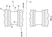
- the bearing 22 of FIG. 2 includes an inner race 46, an outer race 48 and a plurality of rolling elements 50.
- the inner race 46 circumscribes and is mounted to a respective one of the rotating structures 18; e.g., the shaft 26A, 26B (generally referred to as "26").
- the outer race 48 circumscribes the inner race 46 and the rolling elements 50.
- the outer race 48 is mounted to the stationary structure 20 and a respective one of its bearing support structures 40.
- the rolling elements 50 are arranged circumferentially about the rotational axis 32 in an annular array (e.g., radially) between the inner race 46 and the outer race 48. Each of these rolling elements 50 (e.g., radially) engages and is rotatable along the inner race 46 and/or the outer race 48.
- each bearing 22 rotatably mounts the respective rotating structure 18 and its shaft 26 to the respective bearing support structure 40. The rotating structure 18 is thereby configured to rotate about the rotational axis 32.
- This air is directed into at least a core flowpath which extends sequentially through the engine sections 28A, 28B, 30, 29B and 29A (e.g., an engine core) to the exhaust 44.
- the air within this core flowpath may be referred to as "core air”.
- the core air is compressed by the first compressor rotor 24A and the second compressor rotor 24B and directed into a combustion chamber 52 of a combustor in the combustor section 30.
- Fuel is injected into the combustion chamber 52 and mixed with the compressed core air to provide a fuel-air mixture.
- This fuel-air mixture is ignited and combustion products thereof flow through and sequentially cause the second turbine rotor 25B and the first turbine rotor 25A to rotate.
- the rotation of the second turbine rotor 25B and the first turbine rotor 25A respectively drive rotation of the second compressor rotor 24B and the first compressor rotor 24A and, thus, compression of the air received from the airflow inlet 42.
- the rotation of the first turbine rotor 25A also drives rotation of the mechanical load 12 and its rotor 16.
- the rotor 16 is configured as the propulsor rotor
- the rotor 16 propels additional air through or outside of the gas turbine engine system 14 to provide, for example, a majority of aircraft propulsion system thrust.
- the rotor 16 is configured as the generator rotor
- rotation of the rotor 16 facilitates generation of electricity.
- FIG. 3 illustrates a system for the powerplant 10 where the gas turbine engine system 14 supported by a cradle 54; e.g., a storage and/or shipment support, fixture, frame, etc.
- the gas turbine engine system 14 is secured to the cradle 54 for storage and/or transportation of the gas turbine engine system 14.
- the stationary structure 20, for example, may be fixedly attached to the cradle 54 (e.g., via one or more mounts 56) such that the stationary structure 20 does not move relative to the cradle 54.
- the gas turbine engine system 14 While supported by the cradle 54, the gas turbine engine system 14 may be referred to as a "cradled gas turbine engine system".
- the mechanical load 12 and its rotor 16 may be connected to the cradled gas turbine engine system 14. Alternatively, the mechanical load 12 and its rotor 16 may be disconnected from the cradled gas turbine engine system 14 where, for example, the mechanical load 12 and its rotor 16 are stored and/or shipped discrete from the gas turbine engine system 14.
- the cradled gas turbine engine system 14 may be loaded onto a vehicle 58 for shipment; e.g., a ground vehicle such as a truck, a train, etc.
- the vehicle 58 may then transport the cradled gas turbine engine system 14 (with or without the mechanical load 12) at least partially or completely between the first location A and the second location B.
- the vehicle 58 may move up-and-down (e.g., direction 60 in FIG. 4 ), move side-to-side (e.g., direction 62 in FIG. 4 ), bounce, vibrate and/or otherwise be jostled about.
- This vehicle jostling may be caused by, for example, imperfections (e.g., bumps, holes, etc.) in a road, poor and/or worn vehicle suspension, etc.
- the vehicle jostling may subject the cradled gas turbine engine system 14 and its various components to relatively large (e.g., momentary, periodic, etc.) loads; e.g., shock loads.
- the static rolling elements 50 of FIG. 2 may form one or more depressions (e.g., imprints, indentations, etc.) in an (e.g., cylindrical) outer surface 64 of the inner race 46 and/or an (e.g., cylindrical) inner surface 66 of the outer race 48.
- This bearing damage may be characterized as "brinelling" or "false brinelling".
- the gas turbine engine system 14 (see FIG. 1 ) and one or more of its bearings 22 may thereby need maintenance and/or repair even before assembly on, for example, an aircraft, which increases costs and downtime.
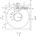
- FIG. 4 illustrates a passive actuation system 68 configured with the cradled gas turbine engine system 14.
- This actuation system 68 is configured to passively rotate (e.g., oscillate) at least one of the rotating structures 18 (e.g., 18A) about its rotational axis 32 while the powerplant 10 (see FIG. 1 ) and its gas turbine engine system 14 are non-operational.
- the actuation system 68 of FIG. 4 is configured to passively rotate the first rotating structure 18A during transportation of the cradled gas turbine engine system 14.
- the bearings 22A (see FIGS. 1 and 2 ) supporting the first rotating structure 18A may be less susceptible to damage such as brinelling / false brinelling.
- the actuation system 68 of FIG. 4 includes an eccentric mass 70, a spring 72 and a damper 74.
- the actuation system 68 of FIG. 4 also includes a fixture 76 for attaching the mass 70 to the first rotating structure 18A.
- This fixture 76 of FIG. 4 includes a hub 78 and a lever arm 80 connected to and projecting radially out from the hub 78 and the rotational axis 32.
- the hub 78 is coupled to the first rotating structure 18A.
- the hub 78 of FIG. 4 for example, is attached to the first shaft 26A via, for example, a bolted connection.
- the fixture 76 and its hub 78 my alternatively be indirectly attached to the first rotating structure 18A (see FIG.
- the fixture 76 may be omitted and the mass 70 may be coupled to the first rotating structure 18A in another manner.
- the mass 70 of FIG. 6 is attached directly to a rotor 82; e.g., a bladed rotor.
- This rotor 82 may be one of the gas turbine engine system rotors 24A, 25A or the mechanical load rotor 16.
- a respective one of the rotor blades 84 may function as the lever arm 80.
- the mass 70 of FIG. 4 is configured to rotationally imbalance the first rotating structure 18A about the rotational axis 32.
- the mass 70 of FIG. 4 for example, is attached to (or integral with) the lever arm 80 at (e.g., on, adjacent or proximate) or radially towards a distal outer end 86 of the lever arm 80.
- at least a center of gravity 88 of the mass 70 may be spaced a radial distance from the rotational axis 32.
- the mass 70 may be similarly located radially out from the rotational axis 32 when otherwise coupled to the first rotating structure 18A; e.g., see FIG. 6 .
- the spring 72 of FIG. 4 is configured to bias a rotating structure system 90 away from a static rotational equilibrium position.
- the rotating structure system 90 may have a stable rotational equilibrium position where the center of gravity 88 of the mass 70 is located at a gravitational bottom center position (see position C in FIG. 7 ).
- the rotating structure system 90 may have an unstable rotational equilibrium position where the center of gravity 88 of the mass 70 is located at a gravitational top center position (see position D in FIG. 7 ).
- the rotating structure system 90 of FIG. 4 includes at least (or only) the first rotating structure 18A, the mass 70 and the fixture 76.
- the rotating structure system 90 of FIG. 6 includes at least (or only) the rotor 82, the first rotating structure 18A and the mass 70.
- the spring 72 extends between and is connected to a stationary object and the rotating structure system 90.
- the spring 72 of FIG. 4 for example, extends between and to a first end 92 of the spring 72 and a second end 94 of the spring 72.
- This spring 72 is attached to the cradle 54 (or the stationary structure 20, or another object) at the spring first end 92.
- the spring 72 is attached to the fixture 76 and its lever arm 80 at the spring second end 94.
- the spring 72 of FIG. 4 is configured to maintain a position of the mass 70 (and its center of gravity 88) to a lateral (e.g., right or left) side of the rotational axis 32.
- the spring 72 may thereby maintain the rotating structure system 90 out of its bottom and/or its top static rotational equilibrium positions (see FIG. 7 ).
- the spring 72 may be configured as a coil spring.
- the spring 72 may be configured as a torsion spring, a resistance band (e.g., an elastic band) or any other type of resilient device.
- the damper 74 is configured to damp rotational movement of the rotating structure system 90 and its first rotating structure 18A about the rotational axis 32.
- the damper 74 extends between and is connected to a stationary object and the rotating structure system 90.
- the damper 74 of FIG. 4 for example, extends between and to a first end 96 of the damper 74 and a second end 98 of the damper 74.
- This damper 74 is attached to the cradle 54 (or the stationary structure 20, or another object) at the damper first end 96.
- the damper 74 is attached to the fixture 76 and its lever arm 80 at the damper second end 98.
- the fixture 76 and its lever arm 80 are disposed between the spring 72 and the damper 74.
- the present disclosure is not limited to such an exemplary arrangement.
- the spring 72 and the damper 74 may alternatively be arranged on a common side of the fixture 76 and its lever arm 80.
- FIG. 8 is a flow diagram of a method 800 for transporting the powerplant 10 and its gas turbine engine system 14.
- the method 800 is described with respect to the actuation system 68 described herein.
- the method 800 of the present disclosure is not limited to any particular actuation system types or configurations.
- the method 800 of the present disclosure is also not limited to the above exemplary powerplant configuration.
- step 802 the gas turbine engine system 14 is arranged with the cradle 54 to provide the cradled gas turbine engine system 14.
- step 804 the actuation system 68 is arranged with the gas turbine engine system 14. This step 804 may occur before, during and/or after the performance of the step 802.
- the cradled gas turbine engine system 14 is transported; e.g., from the first location A to the second location B.
- the vehicle 58 transporting the cradled gas turbine engine system 14 may move laterally side-to-side and/or vertically up-and-down.
- the actuation system 68 may passively transform this laterally side-to-side (see direction 62 in FIG. 4 ) and/or vertically up-and-down movement (see direction 60 in FIG. 4 ) into rotational movement of the rotating structure system 90 and its first rotating structure 18A about the rotational axis 32.
- the movement of the vehicle 58 and, thus, the corresponding movement of the cradled gas turbine engine system 14 may disrupt a static equilibrium of the rotating structure system 90; e.g., a position maintained by the spring 72 when the cradled gas turbine engine system 14 is stationary.
- the rotating structure system 90 may thereby begin to rotationally oscillate about the rotational axis 32.
- the mass 70 and its center of gravity 88 may move down vertically.
- a force of the spring 72 may then cause the mass 70 and its center of gravity 88 to move back vertically up thereby starting or continuing the oscillations.
- the mass 70 and its center of gravity 88 may move up vertically.
- a force of the spring 72 may then cause the mass 70 and its center of gravity 88 to move back vertically down thereby starting or continuing the oscillations.
- This movement of the rotating structure system 90 may reduce or prevent damage (e.g., brinelling / false brinelling) to at least the bearings 22A supporting the first rotating structure 18A during the transportation of the gas turbine engine system 14.
- the rotational oscillations of the rotating structure system 90 may be damped via the damper 74 such that the rotational oscillations are relatively slow, controlled and smooth.
- the mass 70 is eccentrically positioned such that a weight of the mass 70 is greater than an inertia of the rotating structure system 90 and/or expected transportation accelerations from side-to-side and/or up-and-down shifts.
- a spring constant of the spring 72 and/or a damping constant of the damper 74 may be relatively low to keep the rotating structure system 90 minimally unstable.
- the gas turbine engine system 14 is operated.
- the actuation system 68 is removed from the gas turbine engine system 14.
- the gas turbine engine system 14 may (e.g., then) be removed from the cradle 54 and configured for test operation in a test stand (or alternatively in the cradle 54).
- the gas turbine engine system 14 may alternatively be assembled with an aircraft, and subsequently operated for testing and/or aircraft flight.
- the actuation system 68 is decoupled from the gas turbine engine system 14.
- the actuation system 68 passively rotates the first rotating structure 18A while the gas turbine engine is non-operational as described above.
- the actuation system 68 and the method 800 are described above with respect to a single lever arm 80, a single mass 70, a single spring 72 and a single damper 74.
- the present disclosure is not limited to such a singular configuration.
- the actuation system 68 may include multiple masses 70 where the masses 70 are arranged such that the rotating structure system 90 is rotationally imbalanced.
- the actuation system 68 may also or alternatively include one or more additional springs 72 and/or dampers 74.
- the actuation system 68 may be configured without one or more of the elements 72 and/or 74.
- the actuation system 68 for example, may alternatively be configured without a spring 72 and/or a damper 74.
- the actuation system 68 may also or alternatively passively rotate the second rotating structure 18B.
- the actuation system 68 may be rotationally coupled to the second rotating structure 18B (and/or still another rotating assembly) through, for example, an accessory gearbox.
- the powerplant 10 and its gas turbine engine assembly may be configured without the second rotating structure 18B; e.g., the powerplant 10 may be configured as a single spool gas turbine engine.
Abstract
A powerplant system includes a gas turbine engine system (14) and an actuation system (68). The gas turbine engine system (14) includes a rotating structure (18A), a stationary structure (20) and one or more bearings rotatably mounting the rotating structure (18A) to the stationary structure (20). The actuation system (68) is configured to passively rotate the rotating structure (18A) about a rotational axis (32) during transportation of the gas turbine engine system (14).
Description
- This disclosure relates generally to a gas turbine engine and, more particularly, to systems and methods for transporting the gas turbine engine.
- During transportation, a gas turbine engine and its internal components may be subject to shock loads. These shock loads may damage and/or degrade some of the internal components such as bearings. Various systems and methods are known in the art for reducing the impact of shock loads on a gas turbine engine and its internal components. While these known systems and methods have various advantages, there is still room in the art for improvement.
- According to an aspect of the invention, a powerplant system is provided that includes a gas turbine engine system and an actuation system. The gas turbine engine system includes a rotating structure, a stationary structure and one or more bearings rotatably mounting the rotating structure to the stationary structure. The actuation system is configured to passively rotate the rotating structure about a rotational axis during transportation of the gas turbine engine system.
- According to another aspect of the invention, another powerplant system is provided that includes a gas turbine engine system and an eccentric mass. The gas turbine engine system includes a rotating structure, a stationary structure and one or more bearings rotatably mounting the rotating structure to the stationary structure. The eccentric mass is attached to the rotating structure. The eccentric mass rotationally unbalances the rotating structure about a rotational axis such that the rotational structure rotationally oscillates about a rotational axis during non-operational movement of the gas turbine engine system.
- According to another aspect of the invention, a powerplant system comprises a gas turbine engine system including a rotating structure, a stationary structure and one or more bearings rotatably mounting the rotating structure to the stationary structure; and an eccentric mass attached to the rotating structure , the eccentric mass rotationally unbalancing the rotating structure about a rotational axis such that the rotating structure rotationally oscillates about a rotational axis during non-operational movement of the gas turbine engine system.
- The powerplant system of any of the above may further comprise a spring configured to bias a rotating structure system away from a rotational equilibrium position, the rotating structure system including the rotating structure and the eccentric mass.
- The powerplant system of any of the above may further comprise a damper configured to damp the rotational oscillations of the rotating structure about the rotational axis.
- According to still another aspect of the invention, a method is provided for a gas turbine engine system. During this method, the gas turbine engine system is transported from a first location to a second location, where the gas turbine engine system is non-operational during the transporting. A rotating structure is rotated within the gas turbine engine system about a rotational axis using energy from movement of the gas turbine engine system during the transporting.
- The gas turbine engine system may be transported by a ground vehicle.
- The method may also include arranging a mass with the rotating structure to imbalance the rotating structure about the rotational axis. The rotating structure may be passively rotated using the mass.
- The method may also include biasing a rotating structure system away from a rotational equilibrium position about the rotational axis. The rotating structure system may include the rotating structure.
- The method may also include damping the rotation of the rotating structure about the rotational axis.
- The powerplant system may also include a spring configured bias a rotating structure system away from a rotational equilibrium position. The rotating structure system may include the rotating structure and the eccentric mass.
- The powerplant system may also include a damper configured to damp the rotational oscillations of the rotating structure about the rotational axis.
- The actuation system may be configured to passively rotate the rotating structure using energy from movement of the gas turbine engine system during the transportation.
- The movement may include: lateral movement of the gas turbine engine system during the transportation; and/or vertical movement of the gas turbine engine system during the transportation.
- The actuation system may include a mass attached to the rotating structure. The mass may rotationally imbalance the rotating structure about the rotational axis.
- The actuation system may also include a spring configured bias a rotating structure system away from a rotational equilibrium position. The rotating structure system may include the rotating structure and the mass.
- The actuation system may also include a damper configured to damp rotational oscillations of the rotating structure about the rotational axis.
- The actuation system may include a spring configured to provide controlled rotational oscillations of the rotating structure about the rotational axis.
- The actuation system may include a damper configured to damp the rotational oscillations of the rotating structure about the rotational axis.
- The powerplant system may also include a cradle supporting the gas turbine engine system.
- The stationary structure may be rigidly attached to the cradle.
- The actuation system may be mounted to the cradle and the rotating structure.
- The gas turbine engine system may be configured as part of a turbofan gas turbine engine. The gas turbine engine system may be configured as part of a turbojet gas turbine engine.
- The gas turbine engine system may be configured as part of a turboprop gas turbine engine.
- The gas turbine engine system may be configured as part of a turboshaft gas turbine engine.
- The gas turbine engine system may be configured as part of an auxiliary power unit.
- The invention, or aspects of the invention, may include any one or more of the individual features disclosed above and/or below alone or in any combination thereof.
- The foregoing features and the operation of the invention will become more apparent in light of the following description and the accompanying drawings.
-
-
FIG. 1 is a side schematic illustration of a powerplant. -
FIG. 2 is a side sectional illustration of a portion of the powerplant at a bearing rotatably mounting a rotating structure to a stationary structure. -
FIG. 3 is a side schematic illustration of a gas turbine engine system supported by a cradle on a vehicle, where the vehicle is travelling from a first location to a second location. -
FIG. 4 is an end schematic illustration of a cradled gas turbine engine system configured with a passive actuation system, where an actuation system fixture is mounted to a rotating structure shaft. -
FIG. 5 is an end schematic illustration of the cradled gas turbine engine system configured with the actuation system, where the actuation system fixture is mounted to a bladed rotor. -
FIG. 6 is an end schematic illustration of the cradled gas turbine engine system configured with the actuation system, where the actuation system is configured without a fixture. -
FIG. 7 is an end schematic illustration of the cradled gas turbine engine system configured with a portion of the actuation system, where an eccentric mass is at a static rotational equilibrium position. -
FIG. 8 is a flow diagram of a method for transporting the powerplant. -
FIG. 1 is a schematic illustration of apowerplant 10 for an aircraft. Thispowerplant 10 may be included within an aircraft propulsion system. Thepowerplant 10, for example, may be configured as a turbofan gas turbine engine, a turbojet gas turbine engine, a turboprop gas turbine engine or a turboshaft gas turbine engine. Thepowerplant 10 may alternatively be included within an electrical power generation system. Thepowerplant 10, for example, may be configured as an auxiliary power unit (APU). Thepowerplant 10 of the present disclosure, however, is not limited to the foregoing exemplary gas turbine engine types. Furthermore, thepowerplant 10 may also be configured for non-aircraft applications. Thepowerplant 10, for example, may be configured as a (e.g., ground-based) industrial gas turbine engine for an electrical power generation system. - The
powerplant 10 ofFIG. 1 includes amechanical load 12 and a gasturbine engine system 14 configured to drive rotation of themechanical load 12. Themechanical load 12 is configured as or otherwise includes arotor 16 of thepowerplant 10. Themechanical load 12, for example, may be configured as a bladed propulsor rotor for the aircraft propulsion system. Examples of the propulsor rotor include, but are not limited to: a fan rotor for the turbofan gas turbine engine; a compressor rotor for the turbojet gas turbine engine; a propeller rotor for the turboprop gas turbine engine; and a helicopter rotor (e.g., a main rotor) for the turboshaft gas turbine engine. Themechanical load 12 may alternatively be configured as a generator rotor for the power generation system. - The gas
turbine engine system 14 ofFIG. 1 includes one or morerotating structures stationary structure 20. This gasturbine engine system 14 also includes one ormore bearings stationary structure 20. - The first (e.g., low speed)
rotating structure 18A includes a first (e.g., low pressure (LP))compressor rotor 24A, a first (e.g., low pressure)turbine rotor 25A and a first (e.g., low speed)shaft 26A. Thefirst compressor rotor 24A is arranged within and part of a first (e.g., low pressure)compressor section 28A of the gasturbine engine system 14. Thefirst turbine rotor 25A is arranged within and part of a first (e.g., low pressure)turbine section 29A of the gasturbine engine system 14. Thefirst shaft 26A extends axially along arotational axis 32 between and is connected to thefirst compressor rotor 24A and thefirst turbine rotor 25A. - The first
rotating structure 18A may also be rotatably coupled to themechanical load 12 and itsrotor 16. Themechanical load 12 and itsrotor 16, for example, may be coupled to the firstrotating structure 18A through a direct drive coupling. This direct drive coupling may be configured as or otherwise include anoutput shaft 34. With such a direct drive coupling, themechanical load 12 and itsrotor 16 and the firstrotating structure 18A may rotate at a common (e.g., the same) rotational speed. Alternatively, themechanical load 12 and itsrotor 16 may be coupled to the firstrotating structure 18A through a geartrain 36 (see dashed line); e.g., a transmission. Thisgeartrain 36 may be configured as an epicyclic geartrain. With such a geared coupling, themechanical load 12 and itsrotor 16 may rotate at a different (e.g., slower) rotational speed than the firstrotating structure 18A. - The second (e.g., high speed)
rotating structure 18B includes a second (e.g., high pressure (HP))compressor rotor 24B, a second (e.g., high pressure)turbine rotor 25B and a second (e.g., high speed)shaft 26B. Thesecond compressor rotor 24B is arranged within and part of a second (e.g., high pressure)compressor section 28B of the gasturbine engine system 14. Thesecond turbine rotor 25B is arranged within and part of a second (e.g., high pressure)turbine section 29B of the gasturbine engine system 14. Thesecond shaft 26B extends axially along therotational axis 32 between and is connected to thesecond compressor rotor 24B and thesecond turbine rotor 25B. The secondrotating structure 18B ofFIG. 1 and itssecond shaft 26B axially overlap and circumscribe thefirst shaft 26A; however, the gasturbine engine system 14 of the present disclosure is not limited to such an exemplary arrangement. - The
stationary structure 20 includes anengine case 38 and one or morebearing support structures 40. Theengine case 38 is configured to at least partially or completely house thefirst compressor section 28A, thesecond compressor section 28B, acombustor section 30 of the gasturbine engine system 14, thesecond turbine section 29B and thefirst turbine section 29A, whichengine sections rotational axis 32 between anairflow inlet 42 to the gasturbine engine system 14 and anexhaust 44 from the gasturbine engine system 14. Theengine case 38 ofFIG. 1 axially overlaps and extends circumferentially about (e.g., completely around) the firstrotating structure 18A and the secondrotating structure 18B. The bearingsupport structures 40 are disposed within and are connected to theengine case 38. These bearingsupport structures 40 are configured to structurally tie thebearings 22 to theengine case 38. - Referring to
FIG. 2 , each bearing 22 may be configured as a rolling element bearing; e.g., a roller bearing. Examples of the rolling element bearing include, but are not limited to, a cylindrical roller bearing, a spherical roller bearing, a tapered roller bearing and a ball bearing. The bearing 22 ofFIG. 2 , for example, includes aninner race 46, anouter race 48 and a plurality of rollingelements 50. Theinner race 46 circumscribes and is mounted to a respective one of the rotating structures 18; e.g., theshaft outer race 48 circumscribes theinner race 46 and the rollingelements 50. Theouter race 48 is mounted to thestationary structure 20 and a respective one of itsbearing support structures 40. The rollingelements 50 are arranged circumferentially about therotational axis 32 in an annular array (e.g., radially) between theinner race 46 and theouter race 48. Each of these rolling elements 50 (e.g., radially) engages and is rotatable along theinner race 46 and/or theouter race 48. With this arrangement, each bearing 22 rotatably mounts the respective rotating structure 18 and its shaft 26 to the respectivebearing support structure 40. The rotating structure 18 is thereby configured to rotate about therotational axis 32. - Referring to
FIG. 1 , during operation of thepowerplant 10, air enters the gasturbine engine system 14 through theairflow inlet 42. This air is directed into at least a core flowpath which extends sequentially through theengine sections exhaust 44. The air within this core flowpath may be referred to as "core air". - The core air is compressed by the
first compressor rotor 24A and thesecond compressor rotor 24B and directed into acombustion chamber 52 of a combustor in thecombustor section 30. Fuel is injected into thecombustion chamber 52 and mixed with the compressed core air to provide a fuel-air mixture. This fuel-air mixture is ignited and combustion products thereof flow through and sequentially cause thesecond turbine rotor 25B and thefirst turbine rotor 25A to rotate. The rotation of thesecond turbine rotor 25B and thefirst turbine rotor 25A respectively drive rotation of thesecond compressor rotor 24B and thefirst compressor rotor 24A and, thus, compression of the air received from theairflow inlet 42. The rotation of thefirst turbine rotor 25A also drives rotation of themechanical load 12 and itsrotor 16. Where therotor 16 is configured as the propulsor rotor, therotor 16 propels additional air through or outside of the gasturbine engine system 14 to provide, for example, a majority of aircraft propulsion system thrust. Where therotor 16 is configured as the generator rotor, rotation of therotor 16 facilitates generation of electricity. -
FIG. 3 illustrates a system for thepowerplant 10 where the gasturbine engine system 14 supported by acradle 54; e.g., a storage and/or shipment support, fixture, frame, etc. The gasturbine engine system 14 is secured to thecradle 54 for storage and/or transportation of the gasturbine engine system 14. Thestationary structure 20, for example, may be fixedly attached to the cradle 54 (e.g., via one or more mounts 56) such that thestationary structure 20 does not move relative to thecradle 54. While supported by thecradle 54, the gasturbine engine system 14 may be referred to as a "cradled gas turbine engine system". - The
mechanical load 12 and itsrotor 16 may be connected to the cradled gasturbine engine system 14. Alternatively, themechanical load 12 and itsrotor 16 may be disconnected from the cradled gasturbine engine system 14 where, for example, themechanical load 12 and itsrotor 16 are stored and/or shipped discrete from the gasturbine engine system 14. - During transportation of the gas
turbine engine system 14 from a first location A (e.g., a powerplant assembly facility) to a second location B (e.g., an aircraft assembly facility), the cradled gasturbine engine system 14 may be loaded onto avehicle 58 for shipment; e.g., a ground vehicle such as a truck, a train, etc. Thevehicle 58 may then transport the cradled gas turbine engine system 14 (with or without the mechanical load 12) at least partially or completely between the first location A and the second location B. - During transportation of the gas
turbine engine system 14, thevehicle 58 may move up-and-down (e.g.,direction 60 inFIG. 4 ), move side-to-side (e.g.,direction 62 inFIG. 4 ), bounce, vibrate and/or otherwise be jostled about. This vehicle jostling may be caused by, for example, imperfections (e.g., bumps, holes, etc.) in a road, poor and/or worn vehicle suspension, etc. The vehicle jostling may subject the cradled gasturbine engine system 14 and its various components to relatively large (e.g., momentary, periodic, etc.) loads; e.g., shock loads. When the rotating structures 18 are not rotating about therotational axis 32, such loads may damage one or more internal components such as thebearings 22. The staticrolling elements 50 ofFIG. 2 , for example, may form one or more depressions (e.g., imprints, indentations, etc.) in an (e.g., cylindrical)outer surface 64 of theinner race 46 and/or an (e.g., cylindrical)inner surface 66 of theouter race 48. This bearing damage may be characterized as "brinelling" or "false brinelling". The gas turbine engine system 14 (seeFIG. 1 ) and one or more of itsbearings 22 may thereby need maintenance and/or repair even before assembly on, for example, an aircraft, which increases costs and downtime. -
FIG. 4 illustrates apassive actuation system 68 configured with the cradled gasturbine engine system 14. Thisactuation system 68 is configured to passively rotate (e.g., oscillate) at least one of the rotating structures 18 (e.g., 18A) about itsrotational axis 32 while the powerplant 10 (seeFIG. 1 ) and its gasturbine engine system 14 are non-operational. Theactuation system 68 ofFIG. 4 , for example, is configured to passively rotate the firstrotating structure 18A during transportation of the cradled gasturbine engine system 14. By rotating the firstrotating structure 18A about therotational axis 32, thebearings 22A (seeFIGS. 1 and2 ) supporting the firstrotating structure 18A may be less susceptible to damage such as brinelling / false brinelling. - The
actuation system 68 ofFIG. 4 includes aneccentric mass 70, aspring 72 and adamper 74. Theactuation system 68 ofFIG. 4 also includes afixture 76 for attaching themass 70 to the firstrotating structure 18A. Thisfixture 76 ofFIG. 4 includes ahub 78 and alever arm 80 connected to and projecting radially out from thehub 78 and therotational axis 32. Thehub 78 is coupled to the firstrotating structure 18A. Thehub 78 ofFIG. 4 , for example, is attached to thefirst shaft 26A via, for example, a bolted connection. However, referring toFIG. 5 , thefixture 76 and itshub 78 my alternatively be indirectly attached to the firstrotating structure 18A (seeFIG. 1 ) through at least (or only) one intermediate component; e.g., themechanical load 12 and itsrotor 16. In still other embodiments, referring toFIG. 6 , thefixture 76 may be omitted and themass 70 may be coupled to the firstrotating structure 18A in another manner. Themass 70 ofFIG. 6 , for example, is attached directly to a rotor 82; e.g., a bladed rotor. This rotor 82 may be one of the gas turbineengine system rotors mechanical load rotor 16. In such embodiments, a respective one of therotor blades 84 may function as thelever arm 80. - The
mass 70 ofFIG. 4 is configured to rotationally imbalance the firstrotating structure 18A about therotational axis 32. Themass 70 ofFIG. 4 , for example, is attached to (or integral with) thelever arm 80 at (e.g., on, adjacent or proximate) or radially towards a distalouter end 86 of thelever arm 80. With such an arrangement, at least a center ofgravity 88 of the mass 70 (or an entirety of the mass 70) may be spaced a radial distance from therotational axis 32. Themass 70 may be similarly located radially out from therotational axis 32 when otherwise coupled to the firstrotating structure 18A; e.g., seeFIG. 6 . - The
spring 72 ofFIG. 4 is configured to bias arotating structure system 90 away from a static rotational equilibrium position. Therotating structure system 90, for example, may have a stable rotational equilibrium position where the center ofgravity 88 of themass 70 is located at a gravitational bottom center position (see position C inFIG. 7 ). Therotating structure system 90 may have an unstable rotational equilibrium position where the center ofgravity 88 of themass 70 is located at a gravitational top center position (see position D inFIG. 7 ). Therotating structure system 90 ofFIG. 4 includes at least (or only) the firstrotating structure 18A, themass 70 and thefixture 76. Therotating structure system 90 ofFIG. 5 includes at least (or only) themechanical load rotor 16, the firstrotating structure 18A, themass 70 and thefixture 76. Therotating structure system 90 ofFIG. 6 includes at least (or only) the rotor 82, the firstrotating structure 18A and themass 70. - Referring to
FIG. 4 , thespring 72 extends between and is connected to a stationary object and therotating structure system 90. Thespring 72 ofFIG. 4 , for example, extends between and to afirst end 92 of thespring 72 and asecond end 94 of thespring 72. Thisspring 72 is attached to the cradle 54 (or thestationary structure 20, or another object) at the springfirst end 92. Thespring 72 is attached to thefixture 76 and itslever arm 80 at the springsecond end 94. Thespring 72 ofFIG. 4 is configured to maintain a position of the mass 70 (and its center of gravity 88) to a lateral (e.g., right or left) side of therotational axis 32. Thespring 72 may thereby maintain therotating structure system 90 out of its bottom and/or its top static rotational equilibrium positions (seeFIG. 7 ). - The
spring 72 may be configured as a coil spring. Alternatively, thespring 72 may be configured as a torsion spring, a resistance band (e.g., an elastic band) or any other type of resilient device. - The
damper 74 is configured to damp rotational movement of therotating structure system 90 and its firstrotating structure 18A about therotational axis 32. Thedamper 74 extends between and is connected to a stationary object and therotating structure system 90. Thedamper 74 ofFIG. 4 , for example, extends between and to afirst end 96 of thedamper 74 and asecond end 98 of thedamper 74. Thisdamper 74 is attached to the cradle 54 (or thestationary structure 20, or another object) at the damperfirst end 96. Thedamper 74 is attached to thefixture 76 and itslever arm 80 at the dampersecond end 98. In the embodiment ofFIG. 4 , thefixture 76 and itslever arm 80 are disposed between thespring 72 and thedamper 74. The present disclosure, however, is not limited to such an exemplary arrangement. Thespring 72 and thedamper 74, for example, may alternatively be arranged on a common side of thefixture 76 and itslever arm 80. -
FIG. 8 is a flow diagram of amethod 800 for transporting thepowerplant 10 and its gasturbine engine system 14. For ease of description, themethod 800 is described with respect to theactuation system 68 described herein. Themethod 800 of the present disclosure, however, is not limited to any particular actuation system types or configurations. Themethod 800 of the present disclosure is also not limited to the above exemplary powerplant configuration. - In
step 802, the gasturbine engine system 14 is arranged with thecradle 54 to provide the cradled gasturbine engine system 14. - In
step 804, theactuation system 68 is arranged with the gasturbine engine system 14. Thisstep 804 may occur before, during and/or after the performance of thestep 802. - In
step 806, the cradled gasturbine engine system 14 is transported; e.g., from the first location A to the second location B. During this transportation, thevehicle 58 transporting the cradled gasturbine engine system 14 may move laterally side-to-side and/or vertically up-and-down. Theactuation system 68 may passively transform this laterally side-to-side (seedirection 62 inFIG. 4 ) and/or vertically up-and-down movement (seedirection 60 inFIG. 4 ) into rotational movement of therotating structure system 90 and its firstrotating structure 18A about therotational axis 32. More particularly, the movement of thevehicle 58 and, thus, the corresponding movement of the cradled gasturbine engine system 14 may disrupt a static equilibrium of therotating structure system 90; e.g., a position maintained by thespring 72 when the cradled gasturbine engine system 14 is stationary. Therotating structure system 90 may thereby begin to rotationally oscillate about therotational axis 32. For example, when thevehicle 58 and the cradled gasturbine engine system 14 move vertically up quickly (e.g., hitting a bump in a road), themass 70 and its center ofgravity 88 may move down vertically. A force of thespring 72 may then cause themass 70 and its center ofgravity 88 to move back vertically up thereby starting or continuing the oscillations. By contrast, when thevehicle 58 and the cradled gasturbine engine system 14 move vertically down quickly (e.g., hitting a pothole in the road), themass 70 and its center ofgravity 88 may move up vertically. A force of thespring 72 may then cause themass 70 and its center ofgravity 88 to move back vertically down thereby starting or continuing the oscillations. This movement of therotating structure system 90 may reduce or prevent damage (e.g., brinelling / false brinelling) to at least thebearings 22A supporting the firstrotating structure 18A during the transportation of the gasturbine engine system 14. The rotational oscillations of therotating structure system 90 may be damped via thedamper 74 such that the rotational oscillations are relatively slow, controlled and smooth. - To facilitate the rotational movement (e.g., oscillations) of the
rotating structure system 90, themass 70 is eccentrically positioned such that a weight of themass 70 is greater than an inertia of therotating structure system 90 and/or expected transportation accelerations from side-to-side and/or up-and-down shifts. A spring constant of thespring 72 and/or a damping constant of thedamper 74, however, may be relatively low to keep therotating structure system 90 minimally unstable. - In
step 808, the gasturbine engine system 14 is operated. For example, at the second location B (e.g., a destination), theactuation system 68 is removed from the gasturbine engine system 14. The gasturbine engine system 14 may (e.g., then) be removed from thecradle 54 and configured for test operation in a test stand (or alternatively in the cradle 54). The gasturbine engine system 14 may alternatively be assembled with an aircraft, and subsequently operated for testing and/or aircraft flight. During operation of thepowerplant 10, theactuation system 68 is decoupled from the gasturbine engine system 14. Thus, theactuation system 68 passively rotates the firstrotating structure 18A while the gas turbine engine is non-operational as described above. - The
actuation system 68 and themethod 800 are described above with respect to asingle lever arm 80, asingle mass 70, asingle spring 72 and asingle damper 74. The present disclosure, however, is not limited to such a singular configuration. Theactuation system 68, for example, may includemultiple masses 70 where themasses 70 are arranged such that therotating structure system 90 is rotationally imbalanced. Theactuation system 68 may also or alternatively include one or moreadditional springs 72 and/ordampers 74. Alternatively, it is contemplated theactuation system 68 may be configured without one or more of theelements 72 and/or 74. Theactuation system 68, for example, may alternatively be configured without aspring 72 and/or adamper 74. - While the
actuation system 68 is described above for passively rotating the firstrotating structure 18A, theactuation system 68 may also or alternatively passively rotate the secondrotating structure 18B. Theactuation system 68, for example, may be rotationally coupled to the secondrotating structure 18B (and/or still another rotating assembly) through, for example, an accessory gearbox. Of course, in other embodiments, thepowerplant 10 and its gas turbine engine assembly may be configured without the secondrotating structure 18B; e.g., thepowerplant 10 may be configured as a single spool gas turbine engine. - While various embodiments of the present disclosure have been described, it will be apparent to those of ordinary skill in the art that many more embodiments and implementations are possible within the scope of the disclosure. For example, the present disclosure as described herein includes several aspects and embodiments that include particular features. Although these features may be described individually, it is within the scope of the present disclosure that some or all of these features may be combined with any one of the aspects and remain within the scope of the disclosure. Accordingly, the present disclosure is not to be restricted except in light of the attached claims and their equivalents.
Claims (15)
- A powerplant system, comprising:a gas turbine engine system (14) including a rotating structure (18A; 18B), a stationary structure (20) and one or more bearings (22) rotatably mounting the rotating structure (18A; 18B) to the stationary structure (20); andan actuation system (68) configured to passively rotate the rotating structure (18A; 18B) about a rotational axis (32) during transportation of the gas turbine engine system (14).
- The powerplant system of claim 1, wherein the actuation system (68) is configured to passively rotate the rotating structure (18A; 18B) using energy from movement of the gas turbine engine system (14) during the transportation.
- The powerplant system of claim 2, wherein the movement comprises:lateral movement of the gas turbine engine system (14) during the transportation; and/orvertical movement of the gas turbine engine system (14) during the transportation.
- The powerplant system of any preceding claim, wherein:the actuation system (68) comprises a mass (70) attached to the rotating structure (18A; 18B); andthe mass (70) rotationally imbalances the rotating structure (18A; 18B) about the rotational axis (32).
- The powerplant system of claim 4, wherein:the actuation system (68) further comprises a spring (72) configured to bias a rotating structure system (90) away from a rotational equilibrium position; andthe rotating structure system (90) includes the rotating structure (18A; 18B) and the mass (70).
- The powerplant system of claim 5, wherein the actuation system (68) further comprises a damper (74) configured to damp rotational oscillations of the rotating structure (18A; 18B) about the rotational axis (32).
- The powerplant system of any of claims 1 to 4, wherein the actuation system (68) comprises a spring (72) configured to provide controlled rotational oscillations of the rotating structure (18A; 18B) about the rotational axis (32).
- The powerplant system of claim 7, wherein the actuation system (68) comprises a damper (74) configured to damp the rotational oscillations of the rotating structure (18A; 18B) about the rotational axis (32).
- The powerplant system of any preceding claim, further comprising a cradle (54) supporting the gas turbine engine system (14), optionally wherein:the stationary structure (20) is rigidly attached to the cradle (54); and/orthe actuation system (68) is mounted to the cradle (54) and the rotating structure (18A; 18B).
- The powerplant system of any preceding claim, wherein the gas turbine engine system (14) is configured as part of:a turbofan gas turbine engine;a turbojet gas turbine engine;a turboprop gas turbine engine;a turboshaft gas turbine engine; oran auxiliary power unit.
- A method for a gas turbine engine system (14), comprising:transporting the gas turbine engine system (14) from a first location to a second location, wherein the gas turbine engine system (14) is non-operational during the transporting; androtating a rotating structure (18A; 18B) within the gas turbine engine system (14) about a rotational axis (32) using energy from movement of the gas turbine engine system (14) during the transporting.
- The method of claim 11, wherein the gas turbine engine system (14) is transported by a ground vehicle (58).
- The method of claim 11 or 12, further comprising arranging a mass (70) with the rotating structure (18A; 18B) to imbalance the rotating structure (18A; 18B) about the rotational axis (32), wherein the rotating structure (18A; 18B) is passively rotated using the mass (70).
- The method of any of claims 11 to 13, further comprising biasing a rotating structure system (90) away from a rotational equilibrium position about the rotational axis (32), wherein the rotating structure system (90) comprises the rotating structure (18A; 18B).
- The method of any of claims 11 to 14, further comprising damping the rotation of the rotating structure (18A; 18B) about the rotational axis (32).
Applications Claiming Priority (1)
| Application Number | Priority Date | Filing Date | Title |
|---|---|---|---|
| US17/722,894 US11767772B1 (en) | 2022-04-18 | 2022-04-18 | Passively rotating a rotating structure of a gas turbine engine during transportation |
Publications (1)
| Publication Number | Publication Date |
|---|---|
| EP4265530A1 true EP4265530A1 (en) | 2023-10-25 |
Family
ID=86053780
Family Applications (1)
| Application Number | Title | Priority Date | Filing Date |
|---|---|---|---|
| EP23168589.2A Pending EP4265530A1 (en) | 2022-04-18 | 2023-04-18 | Passively rotating a rotating structure of a gas turbine engine during transportation |
Country Status (3)
| Country | Link |
|---|---|
| US (1) | US11767772B1 (en) |
| EP (1) | EP4265530A1 (en) |
| CA (1) | CA3197132A1 (en) |
Citations (2)
| Publication number | Priority date | Publication date | Assignee | Title |
|---|---|---|---|---|
| US20100043228A1 (en) * | 2007-12-28 | 2010-02-25 | James Lloyd Daniels | Method of Preparing an Engine for Ferry Flight |
| US10539053B2 (en) * | 2017-07-06 | 2020-01-21 | General Electric Company | Engine transportation apparatus |
Family Cites Families (4)
| Publication number | Priority date | Publication date | Assignee | Title |
|---|---|---|---|---|
| WO2008045063A1 (en) * | 2006-10-12 | 2008-04-17 | United Technologies Corporation | Variable area nozzle assisted gas turbine engine restarting |
| US7857578B2 (en) * | 2007-07-13 | 2010-12-28 | Pratt & Whitney Canada Corp. | Preloading brace for gas turbine engine transportation |
| CN104995399B (en) | 2013-01-07 | 2018-08-17 | 西门子公司 | The transport of direct drive generator |
| US11014513B2 (en) * | 2016-05-18 | 2021-05-25 | Rolls-Royce North American Technologies Inc. | Control of low pressure generator for gas turbine engine |
-
2022
- 2022-04-18 US US17/722,894 patent/US11767772B1/en active Active
-
2023
- 2023-04-14 CA CA3197132A patent/CA3197132A1/en active Pending
- 2023-04-18 EP EP23168589.2A patent/EP4265530A1/en active Pending
Patent Citations (2)
| Publication number | Priority date | Publication date | Assignee | Title |
|---|---|---|---|---|
| US20100043228A1 (en) * | 2007-12-28 | 2010-02-25 | James Lloyd Daniels | Method of Preparing an Engine for Ferry Flight |
| US10539053B2 (en) * | 2017-07-06 | 2020-01-21 | General Electric Company | Engine transportation apparatus |
Also Published As
| Publication number | Publication date |
|---|---|
| US20230332516A1 (en) | 2023-10-19 |
| CA3197132A1 (en) | 2023-10-18 |
| US11767772B1 (en) | 2023-09-26 |
Similar Documents
| Publication | Publication Date | Title |
|---|---|---|
| US9046001B2 (en) | Annular bearing support dampers, gas turbine engines including the same, and methods for the manufacture thereof | |
| EP2400119B1 (en) | Gas turbine engine rotor tip clearance and shaft dynamics system | |
| EP1854962B1 (en) | Turbine engine mid-turbine frames | |
| US8366385B2 (en) | Gas turbine engine front center body architecture | |
| EP2065569A2 (en) | Rotor decoupler system for a gas turbine | |
| EP2511484B1 (en) | Front centerbody support for a gas turbine engine | |
| EP3480938A1 (en) | Resonance vibration control method and system | |
| US20130186105A1 (en) | Anisotropic vibration isolation mounting assembly | |
| EP2113639A2 (en) | Damping systems for use in turbine engines | |
| JP5956290B2 (en) | Gas turbine engine including a broadband damping system and method of manufacturing the same | |
| EP2938847B1 (en) | Installation mounts for a turbine exhaust case | |
| JP2011508237A (en) | Method and system for balancing a turbine rotor assembly | |
| US20130233997A1 (en) | Turbine engine case mount | |
| US20130067931A1 (en) | Gas turbine engine assemblies including strut-based vibration isolation mounts and methods for producing the same | |
| US11767772B1 (en) | Passively rotating a rotating structure of a gas turbine engine during transportation | |
| CA2789465A1 (en) | Gas turbine engine front center body architecture | |
| US9638056B2 (en) | Gas turbine engine and active balancing system | |
| US9803481B2 (en) | Reduced vibratory response rotor for a gas powered turbine | |
| CA2912395C (en) | Turbine engine assembly and method of manufacturing thereof | |
| US11698027B2 (en) | System for vibration management in rotating machinery | |
| CA3152682A1 (en) | Gas turbine engine and mount assembly therefor | |
| US20220120218A1 (en) | Damper engine mount links | |
| US11168582B2 (en) | Aircraft turbomachine comprising decoupling means | |
| US10808753B1 (en) | Method and apparatus for mounting multiple bearings on a shaft | |
| EP2584154A2 (en) | Method of servicing a gas turbine engine and gas turbine front center body architecture |
Legal Events
| Date | Code | Title | Description |
|---|---|---|---|
| STAA | Information on the status of an ep patent application or granted ep patent |
Free format text: STATUS: THE APPLICATION HAS BEEN PUBLISHED |
|
| PUAI | Public reference made under article 153(3) epc to a published international application that has entered the european phase |
Free format text: ORIGINAL CODE: 0009012 |
|
| AK | Designated contracting states |
Kind code of ref document: A1 Designated state(s): AL AT BE BG CH CY CZ DE DK EE ES FI FR GB GR HR HU IE IS IT LI LT LU LV MC ME MK MT NL NO PL PT RO RS SE SI SK SM TR |
|
| STAA | Information on the status of an ep patent application or granted ep patent |
Free format text: STATUS: REQUEST FOR EXAMINATION WAS MADE |