EP4265517A1 - Aircraft - Google Patents
Aircraft Download PDFInfo
- Publication number
- EP4265517A1 EP4265517A1 EP20965888.9A EP20965888A EP4265517A1 EP 4265517 A1 EP4265517 A1 EP 4265517A1 EP 20965888 A EP20965888 A EP 20965888A EP 4265517 A1 EP4265517 A1 EP 4265517A1
- Authority
- EP
- European Patent Office
- Prior art keywords
- rotors
- wing
- pair
- fuselage
- landing
- Prior art date
- Legal status (The legal status is an assumption and is not a legal conclusion. Google has not performed a legal analysis and makes no representation as to the accuracy of the status listed.)
- Granted
Links
Images


Classifications
-
- B—PERFORMING OPERATIONS; TRANSPORTING
- B64—AIRCRAFT; AVIATION; COSMONAUTICS
- B64C—AEROPLANES; HELICOPTERS
- B64C29/00—Aircraft capable of landing or taking-off vertically, e.g. vertical take-off and landing [VTOL] aircraft
- B64C29/0008—Aircraft capable of landing or taking-off vertically, e.g. vertical take-off and landing [VTOL] aircraft having its flight directional axis horizontal when grounded
- B64C29/0016—Aircraft capable of landing or taking-off vertically, e.g. vertical take-off and landing [VTOL] aircraft having its flight directional axis horizontal when grounded the lift during taking-off being created by free or ducted propellers or by blowers
- B64C29/0025—Aircraft capable of landing or taking-off vertically, e.g. vertical take-off and landing [VTOL] aircraft having its flight directional axis horizontal when grounded the lift during taking-off being created by free or ducted propellers or by blowers the propellers being fixed relative to the fuselage
-
- B—PERFORMING OPERATIONS; TRANSPORTING
- B64—AIRCRAFT; AVIATION; COSMONAUTICS
- B64C—AEROPLANES; HELICOPTERS
- B64C39/00—Aircraft not otherwise provided for
- B64C39/08—Aircraft not otherwise provided for having multiple wings
-
- B—PERFORMING OPERATIONS; TRANSPORTING
- B64—AIRCRAFT; AVIATION; COSMONAUTICS
- B64C—AEROPLANES; HELICOPTERS
- B64C1/00—Fuselages; Constructional features common to fuselages, wings, stabilising surfaces or the like
- B64C1/26—Attaching the wing or tail units or stabilising surfaces
-
- B—PERFORMING OPERATIONS; TRANSPORTING
- B64—AIRCRAFT; AVIATION; COSMONAUTICS
- B64C—AEROPLANES; HELICOPTERS
- B64C3/00—Wings
- B64C3/10—Shape of wings
- B64C3/16—Frontal aspect
Definitions
- the present invention relates to an aircraft capable of taking off and landing in a vertical direction and of cruising.
- US 2020/0115045 A1 discloses an aircraft referred to as a vertical take-off and landing (VTOL) aircraft.
- the aircraft disclosed in US 2020/0115045 A1 includes a fuselage, a front wing and a rear wing (main wing) connected to the fuselage, a plurality of takeoff and landing rotors disposed on the left and right sides of the fuselage, and a plurality of cruise rotors disposed above the rear wing.
- This aircraft uses the takeoff and landing rotors during takeoff and landing and during hovering, and uses the cruise rotors during cruising.
- this aircraft uses both the takeoff and landing rotors and the cruise rotors when transitioning from hovering to cruising and when transitioning from cruising to hovering.
- this aircraft includes a pair of takeoff and landing rotors disposed forward of the front wing or at both ends of the front wing, one or more pairs of takeoff and landing rotors disposed between the front wing and the rear wing, and a pair of takeoff and landing rotors disposed rearward of the rear wing.
- a main wing of an aircraft When air flows to the wing from the front, lift is generated.
- a main wing of an aircraft is configured to generate a large lift at a portion close to a fuselage. Therefore, a large lift can be obtained by smoothly guiding the air flowing from the front, to the vicinity of a connection portion between the main wing and the fuselage.
- a pair of takeoff and landing rotors are disposed forward of the rear wing (main wing) and close to the fuselage.
- the pair of takeoff and landing rotors disposed forward of the rear wing generates, in front of the rear wing, an air flow flowing from above to below. This air flow interferes with the flow of air guided from the front side of the rear wing to the vicinity of the connection portion between the rear wing and the fuselage. Then, the flow of the air guided to the vicinity of the connection portion between the rear wing and the fuselage may be disturbed, and the lift generated by the rear wing may be reduced.
- the present invention has been made in view of such a problem, and an object thereof is to provide an aircraft capable of suppressing a decrease in lift generated by a wing when moving in a horizontal direction while using takeoff and landing rotors.
- an aircraft comprising: a fuselage; a front wing connected to a front portion of the fuselage and configured to generate lift when the aircraft moves in a horizontal direction; a rear wing connected to a rear portion of the fuselage and configured to generate lift when the aircraft moves in the horizontal direction; and four or more rotors configured to generate lift, wherein the four or more rotors include: a pair of first rotors disposed forward of the front wing so as to be bilaterally symmetrical about a position overlapping a central axis of the fuselage in plan view; and a pair of second rotors disposed between the front wing and the rear wing so as to be bilaterally symmetrical about the position overlapping the central axis of the fuselage in the plan view, and wherein a distance between the fuselage and each of the second rotors in a width direction is longer than a distance between the fuselage and each of the first rotors in the width direction.
- an aircraft comprising: a fuselage; a front wing connected to a front portion of the fuselage and configured to generate lift when the aircraft moves in a horizontal direction; a rear wing connected to a rear portion of the fuselage and configured to generate lift when the aircraft moves in the horizontal direction; and four or more rotors configured to generate lift, wherein the four or more rotors include a pair of first rotors and a pair of second rotors, the pair of first rotors and the pair of second rotors each being disposed so as to be bilaterally symmetrical about a position overlapping a central axis of the fuselage in plan view, and wherein a distance, in a front-rear direction, between a center position of the rear wing and a center position between the pair of second rotors is shorter than a distance, in the front-rear direction, between the center position of the rear wing and a center position between the pair of first rotors
- an aircraft comprising: a fuselage; a front wing connected to a front portion of the fuselage and configured to generate lift when the aircraft moves in a horizontal direction; a rear wing connected to a rear portion of the fuselage and configured to generate lift when the aircraft moves in the horizontal direction; and six or more rotors configured to generate lift, wherein the six or more rotors include: a pair of first rotors disposed forward of the front wing so as to be bilaterally symmetrical about a position overlapping a central axis of the fuselage in plan view; a pair of second rotors disposed between the front wing and the rear wing so as to be bilaterally symmetrical about the position overlapping the central axis of the fuselage in the plan view; and a pair of third rotors disposed rearward of the rear wing so as to be bilaterally symmetrical about the position overlapping the central axis of the fuselage in the plan view, and wherein a pair of first rotors disposed forward of the front
- an aircraft 10 is assumed to be an electric vertical take-off and landing (eVTOL) aircraft that generates lift and thrust using rotors each including an electric motor.
- eVTOL electric vertical take-off and landing
- a vertically upward direction is referred to as an upward direction (upward)
- a vertically downward direction is referred to as a downward direction (downward)
- a moving direction of the aircraft 10 when the aircraft 10 moves (flies) in the horizontal direction is referred to as a forward direction (forward)
- a direction opposite thereto is referred to as a rearward direction (rearward).
- a direction toward the right side in the width direction of the aircraft 10 is referred to as a right direction (rightward), and a direction toward the left side in the width direction is referred to as a left direction (leftward).
- the plan view of the aircraft 10 refers to a view in which the respective components are viewed from a position directly above the aircraft 10.
- the front view of the aircraft 10 refers to a view in which the respective components are viewed from a position in front of the aircraft 10.
- the aircraft 10 includes a fuselage 12, a front wing 14, a rear wing 16, two booms 18, eight takeoff and landing rotors 20, and two cruise rotors 22.
- the structure of the aircraft 10 in plan view is bilaterally symmetrical about a position overlapping a central axis A of the fuselage 12 extending in the front-rear direction.
- the central axis A overlaps a center of gravity G of the aircraft 10.
- the fuselage 12 is long in the front-rear direction.
- the fuselage 12 includes a front portion 12f located forward of the center of gravity G, and a rear portion 12r located rearward of the center of gravity G.
- the front portion 12f is configured such that the front end thereof is narrow.
- the rear portion 12r is configured such that the rear end thereof is narrow.
- the main body of the fuselage 12 may be partially covered with a fairing.
- the fuselage 12, the front portion 12f, and the rear portion 12r are referred to as such, including the fairing.
- the front wing 14 is connected to an upper portion of the front portion 12f of the fuselage 12 and is configured to generate lift when the aircraft 10 moves forward.
- the front wing 14 includes a front wing main body (also referred to as a horizontal stabilizer) 26 extending to the left and right (laterally) from the center, and left and right elevators 28 disposed at the trailing edge of the front wing 14.
- the rear wing 16 is connected to an upper portion of the rear portion 12r of the fuselage 12 via a pylon 32 and is configured to generate lift when the aircraft 10 moves forward.
- the rear wing 16 includes a rear wing main body 34 extending laterally rearward from the center, left and right elevons 36 disposed at the trailing edge of the rear wing 16, and a pair of vertical tails 38 disposed at left and right wing tips of the rear wing 16.
- Each vertical tail 38 includes a tail main body 42 (also referred to as a vertical stabilizer), and a rudder 44 disposed at the trailing edge of the vertical tail 38.
- the wing area of the rear wing 16 is larger than the wing area of the front wing 14. Further, the wing width of the rear wing 16 is greater than the wing width of the front wing 14. With such a configuration, when the aircraft 10 moves forward, the lift generated by the rear wing 16 is larger than the lift generated by the front wing 14. That is, the rear wing 16 functions as a main wing of the aircraft 10. The rear wing 16 is a swept wing that reduces air resistance.
- the front wing 14 functions as a canard wing of the aircraft 10.
- the front wing 14 and the rear wing 16 also function as support members for supporting the two booms 18.
- the lift generated by the rear wing 16 when the aircraft 10 moves forward and the lift generated by the front wing 14 when the aircraft 10 moves forward may be substantially the same.
- the magnitude relationship between the lift generated by the front wing 14 and the lift generated by the rear wing 16 is appropriately determined depending on the position of the center of gravity G, the attitude of the fuselage during cruising, and the like. Further, the size (the wing area, the length, and the like) of each of the front wing 14 and the rear wing 16 is determined so as to generate a desired lift.
- the two booms 18 include a right boom 18 disposed on the right side of the fuselage 12, and a left boom 18 disposed on the left side of the fuselage 12.
- the two booms 18 form a pair and are arranged so as to be bilaterally symmetrical about a position overlapping the central axis A of the fuselage 12 in plan view.
- the two booms 18 function as support members for supporting the takeoff and landing rotors 20.
- the right boom 18 is a bar member that extends from the front toward the rear and is curved rightward (outward in the width direction) in an arc shape.
- the right boom 18 is connected to the right wing tip of the front wing 14 and is connected to the right wing of the rear wing 16 on the inner side of the elevon 36.
- the front end of the right boom 18 is located forward of the front wing 14.
- the rear end of the right boom 18 is located rearward of the rear wing 16.
- the left boom 18 is a bar member that extends from the front toward the rear and is curved leftward (outward in the width direction) in an arc shape.
- the left boom 18 is connected to the left wing tip of the front wing 14 and is connected to the left wing of the rear wing 16 on the inner side of the elevon 36.
- the front end of the left boom 18 is located forward of the front wing 14.
- the rear end of the left boom 18 is located rearward of the rear wing 16.
- the takeoff and landing rotors 20 each include a rotating mast (not shown) connected to an output shaft of an electric motor (not shown), and a propeller 46 attached to the rotating mast.
- the rotating mast is disposed so as to be parallel to the up-down direction and is rotatable about an axis extending in the up-down direction.
- the propeller 46 is located above the boom 18, the front wing 14, and the rear wing 16. With such a structure, the propeller 46 is rotatable about an axis extending in the up-down direction.
- Each takeoff and landing rotor 20 generates lift by rotation of the propeller 46.
- the eight takeoff and landing rotors 20 include four takeoff and landing rotors 20a to 20d disposed on the right side of the fuselage 12, and four takeoff and landing rotors 20a to 20d disposed on the left side of the fuselage 12.
- the right-side takeoff and landing rotors 20a to 20d are supported by the right boom 18.
- the left-side takeoff and landing rotors 20a to 20d are supported by the left boom 18.
- Each of the right-side takeoff and landing rotors 20a to 20d and each of the left-side takeoff and landing rotors 20a to 20d form a pair, the position of each right-side takeoff and landing rotor and the position of the left-side takeoff and landing rotor paired with this right-side takeoff and landing rotor being the same in the front-rear direction.
- the pair of takeoff and landing rotors 20a, the front wing 14, the pair of takeoff and landing rotors 20b, the pair of takeoff and landing rotors 20c, the rear wing 16, and the pair of takeoff and landing rotors 20d are arranged in this order from the front toward the rear in plan view.
- the pair of takeoff and landing rotors 20a are disposed forward of the front wing 14.
- the pair of takeoff and landing rotors 20b are disposed between the front wing 14 and the rear wing 16, and are disposed forward of the pair of takeoff and landing rotors 20c.
- the pair of takeoff and landing rotors 20c are disposed between the front wing 14 and the rear wing 16, and are disposed rearward of the pair of takeoff and landing rotors 20b.
- the pair of takeoff and landing rotors 20d are disposed rearward of the rear wing 16. As shown in FIG. 4 , the takeoff and landing rotors 20a to 20d are disposed at the same height position.
- a distance between the fuselage 12 and each takeoff and landing rotor 20a in the width direction is defined as Dx.
- a distance between the fuselage 12 and each takeoff and landing rotor 20b in the width direction is defined as Dy.
- a distance between the fuselage 12 and each takeoff and landing rotor 20c in the width direction is defined as Dz.
- the start point (or end point) of each of the distances Dx to Dz on the fuselage 12 side is a position on the outermost side of the outer surface of the fuselage 12 in plan view.
- the start point (or end point) of each of the distances Dx to Dz on the takeoff and landing rotor 20 side is the position of the axis of the propeller 46.
- the takeoff and landing rotors 20 are arranged so that the following first condition and second condition are satisfied.
- Dx ⁇ Dy , Dx ⁇ Dz Dy Dz
- takeoff and landing rotors 20 may be arranged so that the following third condition is satisfied instead of the second condition.
- a distance between the pair of takeoff and landing rotors 20a is defined as Da.
- a distance between the pair of takeoff and landing rotors 20b is defined as Db.
- a distance between the pair of takeoff and landing rotors 20c is defined as Dc.
- a distance between the pair of takeoff and landing rotors 20d is defined as Dd.
- the start point and the end point of each of the distances Da to Dd are the positions of the axes of the propellers 46.
- the takeoff and landing rotors 20 are arranged so that the following fourth condition and fifth condition are satisfied in addition to the first to third conditions.
- takeoff and landing rotors 20 may be arranged so that the following sixth condition is satisfied instead of the fifth condition.
- Da Dd , Db ⁇ Dc
- a center position Ca between the pair of takeoff and landing rotors 20a and a center position Cb between the pair of takeoff and landing rotors 20b are located forward of the center of gravity G. Further, in plan view, a center position Cc between the pair of takeoff and landing rotors 20c and a center position Cd between the pair of takeoff and landing rotors 20d are located rearward of the center of gravity G.
- a distance between the center of gravity G and the center position Ca between the pair of takeoff and landing rotors 20a is defined as D01.
- a distance between the center of gravity G and the center position Cb between the pair of takeoff and landing rotors 20b is defined as D02.
- a distance between the center of gravity G and the center position Cc between the pair of takeoff and landing rotors 20c is defined as D03.
- a distance between the center of gravity G and the center position Cd between the pair of takeoff and landing rotors 20d is defined as D04.
- the takeoff and landing rotors 20 are arranged so that the following seventh condition is satisfied in addition to the first to sixth conditions.
- a distance between a center position Cw of the rear wing 16 and the center position Cb between the pair of takeoff and landing rotors 20b is defined as D11.
- a distance between the center position Cw of the rear wing 16 and the center position Cc between the pair of takeoff and landing rotors 20c is defined as D12.
- a distance between the center position Cw of the rear wing 16 and the center position Cd between the pair of takeoff and landing rotors 20d is defined as D13.
- the center position Cw of the rear wing 16 may be a center position, in the front-rear direction, of the center line of the rear wing 16 extending in the front-rear direction, or may be the center of gravity of the rear wing 16.
- the takeoff and landing rotors 20 are arranged so that the following eighth condition is satisfied in addition to the first to seventh conditions.
- the pair of takeoff and landing rotors 20a are disposed immediately forward of the front wing 14 in plan view.
- a rotation range 48a of the propeller 46 of each of the takeoff and landing rotors 20a is in contact with or separated from the leading edge of the front wing 14.
- the pair of takeoff and landing rotors 20c are disposed immediately forward of the rear wing 16 in plan view.
- a rotation range 48c of the propeller 46 of each of the takeoff and landing rotors 20c is in contact with or separated from the leading edge of the rear wing 16.
- the rotation ranges 48a and 48c of the propellers 46 of the takeoff and landing rotors 20a and 20c disposed forward of the wings do not overlap the wings in plan view.
- the two cruise rotors 22 are disposed on the rear portion 12r of the fuselage 12.
- the position of each cruise rotor 22 in the left-right direction is on the inner side (the fuselage 12 side) of the position of each pair of takeoff and landing rotors 20 in the left-right direction.
- the position of each cruise rotor 22 in the front-rear direction is between the pair of takeoff and landing rotors 20c and the pair of takeoff and landing rotors 20d.
- the position of the axis of each cruise rotor 22 in the up-down direction is lower than the position of the propeller 46 of each takeoff and landing rotor 20 in the up-down direction.
- the cruise rotors 22 each include a rotating mast (not shown) connected to an output shaft of an electric motor (not shown), a propeller 52 attached to a front end portion of the rotating mast, and a cylindrical duct 54 surrounding the propeller 52.
- the positions of the two cruise rotors 22 coincide with each other in both the front-rear direction and the up-down direction. Further, the two cruise rotors 22 are arranged side by side in the left-right direction.
- One of the cruise rotors 22 is disposed on the right side of a position overlapping the central axis A of the fuselage 12 in plan view, and is supported by the right wing of the rear wing 16.
- the other cruise rotor 22 is disposed on the left side of the position overlapping the central axis A of the fuselage 12 in plan view, and is supported by the left wing of the rear wing 16.
- the rotating mast is located below the rear wing 16 so as to be parallel to the front-rear direction, and is rotatable about an axis extending in the front-rear direction.
- the propeller 52 is rotatable about an axis extending in the front-rear direction.
- Each cruise rotor 22 generates thrust by rotation of the propeller 52.
- the takeoff and landing rotors 20 are used when the aircraft 10 takes off, lands, and hovers.
- the cruise rotors 22 are used when the aircraft 10 is cruising.
- the takeoff and landing rotors 20 and the cruise rotors 22 are used together when the aircraft 10 transitions from hovering to cruising and moves forward at a first speed ( ⁇ 0km/h) or more and less than a second speed (> first speed).
- the usage rate of the cruise rotors 22 is gradually increased for acceleration. Since the lift generated by the wing increases with acceleration, the usage rate of the takeoff and landing rotors 20 is gradually decreased.
- the usage rate of the takeoff and landing rotors 20 is decreased by decreasing the rotational speed of the takeoff and landing rotors 20 to reduce the lift.
- the usage rate of the takeoff and landing rotors 20 is decreased by changing the pitch angle of respective blades to reduce the lift.
- the takeoff and landing rotors 20 and the cruise rotors 22 are used together when the aircraft 10 transitions from cruising to hovering and moves forward at a third speed ( ⁇ 0km/h) or more and less than a fourth speed (> third speed).
- the usage rate of the cruise rotors 22 is gradually decreased for deceleration. Since the lift generated by the wing decreases with deceleration, the usage rate of the takeoff and landing rotors 20 is gradually increased.
- the usage rate of the takeoff and landing rotors 20 is decreased by decreasing the rotational speed of the takeoff and landing rotors 20 to reduce the lift.
- the usage rate of the takeoff and landing rotors 20 is decreased by changing the pitch angle of respective blades to reduce the lift.
- the aircraft 10 may include four takeoff and landing rotors 20, namely, two pairs of takeoff and landing rotors 20.
- the first pair of takeoff and landing rotors 20 are disposed forward of the front wing 14 in plan view.
- the second pair of takeoff and landing rotors 20 are disposed between the front wing 14 and the rear wing 16 in plan view.
- the takeoff and landing rotors 20 are arranged so that the distance, in the width direction, between the fuselage 12 and each of the takeoff and landing rotors 20 disposed between the front wing 14 and the rear wing 16 is longer than the distance, in the width direction, between the fuselage 12 and each of the takeoff and landing rotors 20 disposed forward of the front wing 14.
- the aircraft 10 may include six takeoff and landing rotors 20, namely, three pairs of takeoff and landing rotors 20.
- the first pair of takeoff and landing rotors 20 are disposed forward of the front wing 14 in plan view.
- the second pair of takeoff and landing rotors 20 are disposed between the front wing 14 and the rear wing 16 in plan view.
- the third pair of takeoff and landing rotors 20 are disposed rearward of the rear wing 16 in plan view.
- the takeoff and landing rotors 20 are arranged so that the distance, in the width direction, between the fuselage 12 and each of the takeoff and landing rotors 20 disposed between the front wing 14 and the rear wing 16 is longer than the distance, in the width direction, between the fuselage 12 and each of the takeoff and landing rotors 20 disposed forward of the front wing 14.
- takeoff and landing rotors 20 are arranged so that the distance between the second pair of takeoff and landing rotors 20 disposed between the front wing 14 and the rear wing 16 is longer than the distance between the first pair of takeoff and landing rotors 20 disposed forward of the front wing 14 and the distance between the third pair of takeoff and landing rotors 20 disposed rearward of the rear wing 16.
- the aircraft 10 may include ten or more takeoff and landing rotors 20, namely, five or more pairs of takeoff and landing rotors 20.
- at least one pair of takeoff and landing rotors 20 are disposed forward of the front wing 14 in plan view.
- at least one pair of takeoff and landing rotors 20 are disposed between the front wing 14 and the rear wing 16 in plan view.
- at least one pair of takeoff and landing rotors 20 are disposed rearward of the rear wing 16 in plan view.
- the takeoff and landing rotors 20 are arranged so that the distance, in the width direction, between the fuselage 12 and each of the takeoff and landing rotors 20 disposed between the front wing 14 and the rear wing 16 is longer than the distance, in the width direction, between the fuselage 12 and each of the takeoff and landing rotors 20 disposed forward of the front wing 14.
- takeoff and landing rotors 20 are arranged so that the distance between the pair of takeoff and landing rotors 20 disposed between the front wing 14 and the rear wing 16 is longer than the distance between the pair of takeoff and landing rotors 20 disposed forward of the front wing 14 and the distance between the pair of takeoff and landing rotors 20 disposed rearward of the rear wing 16.
- the aircraft 10 including: the fuselage 12; the front wing 14 connected to the front portion 12f of the fuselage 12 and configured to generate lift when the aircraft moves in the horizontal direction; the rear wing 16 connected to the rear portion 12r of the fuselage 12 and configured to generate lift when the aircraft moves in the horizontal direction; and four or more rotors (the takeoff and landing rotors 20) configured to generate lift, wherein the four or more rotors include: the pair of first rotors (the takeoff and landing rotors 20a) disposed forward of the front wing 14 so as to be bilaterally symmetrical about the position overlapping the central axis A of the fuselage 12 in plan view; and the pair of second rotors (the takeoff and landing rotors 20b, 20c) disposed between the front wing 14 and the rear wing 16 so as to be bilaterally symmetrical about the position overlapping the central axis A of the fuselage 12 in plan view, and wherein the distance (D
- At least the distance (Dy, Dz) between the fuselage 12 and each second rotor in the width direction is longer than the distance (Dx) between the fuselage 12 and each first rotor (the takeoff and landing rotor 20a) in the width direction. That is, a relatively large space is formed between the fuselage 12 and each second rotor. Accordingly, the flow of air guided from the front to the vicinity of the connection portion between the rear wing 16 and the fuselage 12 does not interfere with the downward air flow generated in accordance with the operation of the second rotors.
- the distance (Db, Dc) between the pair of second rotors may be longer than the distance (Da) between the pair of first rotors.
- the center of gravity G of the aircraft 10 may be located between the front wing 14 and the rear wing 16, and the distance (D02, D03), in the front-rear direction, between the center of gravity G and the center position Cb, Cc between the pair of second rotors may be shorter than the distance (D01), in the front-rear direction, between the center of gravity G and the center position Ca between the pair of first rotors.
- the attitude of the aircraft 10 can be stabilized for the following reason.
- the moment of the lift about the center of gravity G increases.
- the pair of first rotors (the takeoff and landing rotors 20a) are disposed farther from the center of gravity G than the pair of second rotors (the takeoff and landing rotors 20b, 20c). Therefore, the moment of the lift about the center of gravity G generated by the pair of first rotors is larger than the moment of the lift about the center of gravity G generated by the pair of second rotors.
- the moment in the roll direction increases as the distance between the pair of first rotors and the fuselage 12 increases.
- the pair of first rotors disposed away from the center of gravity G are closer to the fuselage 12 than the pair of second rotors disposed close to the center of gravity G. That is, the fuselage 12 and each first rotor are relatively close to each other. Therefore, the moment in the roll direction is relatively small.
- the attitude of the aircraft 10 can be stabilized.
- the aircraft may include the pair of bar members (the booms 18) disposed so as to be bilaterally symmetrical about the position overlapping the central axis A of the fuselage 12 in plan view, and the pair of bar members may be connected to the front wing 14 and the rear wing 16, may be curved outward in the width direction, and may support the pair of first rotors and the pair of second rotors.
- the pair of bar members (the booms 18) disposed so as to be bilaterally symmetrical about the position overlapping the central axis A of the fuselage 12 in plan view, and the pair of bar members may be connected to the front wing 14 and the rear wing 16, may be curved outward in the width direction, and may support the pair of first rotors and the pair of second rotors.
- both the front wing 14 and the rear wing 16 support the bar members (the booms 18), it is not necessary to increase the rigidity of the bar members compared to a case where only one of the front wing 14 or the rear wing 16 supports the bar members.
- the rear wing 16 may be a swept wing, and the wing area of the rear wing 16 may be larger than the wing area of the front wing 14, or the wing width of the rear wing 16 may be greater than the wing width of the front wing 14.
- each second rotor (the takeoff and landing rotor 20c) on the outer side in the width direction makes it easier to separate the rotation range 48c of the propeller 46 of the second rotor and the leading edge of the rear wing 16 from each other in the front-rear direction in plan view. Therefore, the downward air flow generated in accordance with the operation of the second rotors is less likely to interfere with the rear wing 16.
- the aircraft 10 including: the fuselage 12; the front wing 14 connected to the front portion 12f of the fuselage 12 and configured to generate lift when the aircraft moves in the horizontal direction; the rear wing 16 connected to the rear portion 12r of the fuselage 12 and configured to generate lift when the aircraft moves in the horizontal direction; and four or more rotors (the takeoff and landing rotors 20) configured to generate lift, wherein the four or more rotors include the pair of first rotors (the takeoff and landing rotors 20b) and the pair of second rotors (the takeoff and landing rotors 20c), the pair of first rotors and the pair of second rotors each being disposed so as to be bilaterally symmetrical about the position overlapping the central axis A of the fuselage 12 in plan view, and wherein the distance (D12), in the front-rear direction, between the center position Cw of the rear wing 16 and the center position Cc between the pair of second rot
- At least the distance (Dz) between the fuselage 12 and each second rotor (the takeoff and landing rotor 20c) in the width direction is longer than the distance (Dy) between the fuselage 12 and each first rotor (the takeoff and landing rotor 20b) in the width direction. That is, a relatively large space is formed between the fuselage 12 and each second rotor. Accordingly, the flow of air guided from the front to the vicinity of the connection portion between the rear wing 16 and the fuselage 12 does not interfere with the downward air flow generated in accordance with the operation of the second rotors.
- the aircraft 10 including: the fuselage 12; the front wing 14 connected to the front portion 12f of the fuselage 12 and configured to generate lift when the aircraft moves in the horizontal direction; the rear wing 16 connected to the rear portion 12r of the fuselage 12 and configured to generate lift when the aircraft moves in the horizontal direction; and six or more rotors (the takeoff and landing rotors 20) configured to generate lift, wherein the six or more rotors include: the pair of first rotors (the takeoff and landing rotors 20a) disposed forward of the front wing 14 so as to be bilaterally symmetrical about the position overlapping the central axis A of the fuselage 12 in plan view; the pair of second rotors (the takeoff and landing rotors 20b, 20c) disposed between the front wing 14 and the rear wing 16 so as to be bilaterally symmetrical about the position overlapping the central axis A of the fuselage 12 in plan view; and the pair of third rotor
- At least the distance (Db, Dc) between the pair of second rotors (the takeoff and landing rotors 20b, 20c) is longer than the distance (Da) between the pair of first rotors (the takeoff and landing rotors 20a) and the distance (Dd) between the pair of third rotors (the takeoff and landing rotors 20d). That is, a relatively large space is formed between the fuselage 12 and each second rotor. Accordingly, the flow of air guided from the front to the vicinity of the connection portion between the rear wing 16 and the fuselage 12 does not interfere with the downward air flow generated in accordance with the operation of the second rotors.
- the width of the aircraft 10 on the front side and the rear side thereof can be reduced. Accordingly, the aircraft 10 can be stored in a small space.
- the aircraft according to the present invention is not limited to the above disclosure, and various configurations could be adopted therein without departing from the essence and gist of the present invention.
Landscapes
- Engineering & Computer Science (AREA)
- Aviation & Aerospace Engineering (AREA)
- Mechanical Engineering (AREA)
- Toys (AREA)
Abstract
Description
- The present invention relates to an aircraft capable of taking off and landing in a vertical direction and of cruising.
-
US 2020/0115045 A1 discloses an aircraft referred to as a vertical take-off and landing (VTOL) aircraft. The aircraft disclosed inUS 2020/0115045 A1 includes a fuselage, a front wing and a rear wing (main wing) connected to the fuselage, a plurality of takeoff and landing rotors disposed on the left and right sides of the fuselage, and a plurality of cruise rotors disposed above the rear wing. This aircraft uses the takeoff and landing rotors during takeoff and landing and during hovering, and uses the cruise rotors during cruising. In addition, this aircraft uses both the takeoff and landing rotors and the cruise rotors when transitioning from hovering to cruising and when transitioning from cruising to hovering. - In this aircraft, two takeoff and landing rotors arranged on the left and right sides of the fuselage form a pair. For example, this aircraft includes a pair of takeoff and landing rotors disposed forward of the front wing or at both ends of the front wing, one or more pairs of takeoff and landing rotors disposed between the front wing and the rear wing, and a pair of takeoff and landing rotors disposed rearward of the rear wing.
- When air flows to the wing from the front, lift is generated. In general, a main wing of an aircraft is configured to generate a large lift at a portion close to a fuselage. Therefore, a large lift can be obtained by smoothly guiding the air flowing from the front, to the vicinity of a connection portion between the main wing and the fuselage.
- In the aircraft disclosed in
US 2020/0115045 A1 , a pair of takeoff and landing rotors are disposed forward of the rear wing (main wing) and close to the fuselage. When the takeoff and landing rotors and the cruise rotors are used together in this aircraft, the pair of takeoff and landing rotors disposed forward of the rear wing generates, in front of the rear wing, an air flow flowing from above to below. This air flow interferes with the flow of air guided from the front side of the rear wing to the vicinity of the connection portion between the rear wing and the fuselage. Then, the flow of the air guided to the vicinity of the connection portion between the rear wing and the fuselage may be disturbed, and the lift generated by the rear wing may be reduced. - The present invention has been made in view of such a problem, and an object thereof is to provide an aircraft capable of suppressing a decrease in lift generated by a wing when moving in a horizontal direction while using takeoff and landing rotors.
- According to a first aspect of the present invention, there is provided an aircraft comprising: a fuselage; a front wing connected to a front portion of the fuselage and configured to generate lift when the aircraft moves in a horizontal direction; a rear wing connected to a rear portion of the fuselage and configured to generate lift when the aircraft moves in the horizontal direction; and four or more rotors configured to generate lift, wherein the four or more rotors include: a pair of first rotors disposed forward of the front wing so as to be bilaterally symmetrical about a position overlapping a central axis of the fuselage in plan view; and a pair of second rotors disposed between the front wing and the rear wing so as to be bilaterally symmetrical about the position overlapping the central axis of the fuselage in the plan view, and wherein a distance between the fuselage and each of the second rotors in a width direction is longer than a distance between the fuselage and each of the first rotors in the width direction.
- According to a second aspect of the present invention, there is provided an aircraft comprising: a fuselage; a front wing connected to a front portion of the fuselage and configured to generate lift when the aircraft moves in a horizontal direction; a rear wing connected to a rear portion of the fuselage and configured to generate lift when the aircraft moves in the horizontal direction; and four or more rotors configured to generate lift, wherein the four or more rotors include a pair of first rotors and a pair of second rotors, the pair of first rotors and the pair of second rotors each being disposed so as to be bilaterally symmetrical about a position overlapping a central axis of the fuselage in plan view, and wherein a distance, in a front-rear direction, between a center position of the rear wing and a center position between the pair of second rotors is shorter than a distance, in the front-rear direction, between the center position of the rear wing and a center position between the pair of first rotors, and a distance between the fuselage and each of the second rotors in a width direction is longer than a distance between the fuselage and each of the first rotors in the width direction.
- According to a third aspect of the present invention, there is provided an aircraft comprising: a fuselage; a front wing connected to a front portion of the fuselage and configured to generate lift when the aircraft moves in a horizontal direction; a rear wing connected to a rear portion of the fuselage and configured to generate lift when the aircraft moves in the horizontal direction; and six or more rotors configured to generate lift, wherein the six or more rotors include: a pair of first rotors disposed forward of the front wing so as to be bilaterally symmetrical about a position overlapping a central axis of the fuselage in plan view; a pair of second rotors disposed between the front wing and the rear wing so as to be bilaterally symmetrical about the position overlapping the central axis of the fuselage in the plan view; and a pair of third rotors disposed rearward of the rear wing so as to be bilaterally symmetrical about the position overlapping the central axis of the fuselage in the plan view, and wherein a distance between the pair of second rotors is longer than a distance between the pair of first rotors and a distance between the pair of third rotors.
- According to each aspect of the present invention, it is possible to suppress a decrease in lift generated by the rear wing due to the operation of the second rotors.
-
-
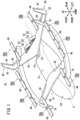
FIG. 1 is a perspective view of an aircraft according to a present embodiment; -
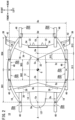
FIG. 2 is a plan view of the aircraft according to the present embodiment; -
FIG. 3 is a plan view showing a rotation range of a propeller of each takeoff and landing rotor; -
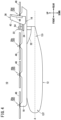
FIG. 4 is a left side view of the aircraft according to the present embodiment; and -
FIG. 5 is a front view of the aircraft according to the present embodiment. - A preferred embodiment of an aircraft according to the present invention will be presented and described in detail below with reference to the accompanying drawings.
- In the present embodiment, an
aircraft 10 is assumed to be an electric vertical take-off and landing (eVTOL) aircraft that generates lift and thrust using rotors each including an electric motor. In this specification, a vertically upward direction is referred to as an upward direction (upward), and a vertically downward direction is referred to as a downward direction (downward). Further, a moving direction of theaircraft 10 when theaircraft 10 moves (flies) in the horizontal direction is referred to as a forward direction (forward), and a direction opposite thereto is referred to as a rearward direction (rearward). Further, in a state of facing forward from theaircraft 10, a direction toward the right side in the width direction of theaircraft 10 is referred to as a right direction (rightward), and a direction toward the left side in the width direction is referred to as a left direction (leftward). Further, the plan view of theaircraft 10 refers to a view in which the respective components are viewed from a position directly above theaircraft 10. The front view of theaircraft 10 refers to a view in which the respective components are viewed from a position in front of theaircraft 10. - The
aircraft 10 includes afuselage 12, afront wing 14, arear wing 16, twobooms 18, eight takeoff andlanding rotors 20, and twocruise rotors 22. As shown inFIG. 2 , the structure of theaircraft 10 in plan view is bilaterally symmetrical about a position overlapping a central axis A of thefuselage 12 extending in the front-rear direction. In plan view, the central axis A overlaps a center of gravity G of theaircraft 10. - The
fuselage 12 is long in the front-rear direction. Thefuselage 12 includes afront portion 12f located forward of the center of gravity G, and arear portion 12r located rearward of the center of gravity G. Thefront portion 12f is configured such that the front end thereof is narrow. Therear portion 12r is configured such that the rear end thereof is narrow. The main body of thefuselage 12 may be partially covered with a fairing. In this specification, thefuselage 12, thefront portion 12f, and therear portion 12r are referred to as such, including the fairing. - The
front wing 14 is connected to an upper portion of thefront portion 12f of thefuselage 12 and is configured to generate lift when theaircraft 10 moves forward. Thefront wing 14 includes a front wing main body (also referred to as a horizontal stabilizer) 26 extending to the left and right (laterally) from the center, and left andright elevators 28 disposed at the trailing edge of thefront wing 14. - The
rear wing 16 is connected to an upper portion of therear portion 12r of thefuselage 12 via apylon 32 and is configured to generate lift when theaircraft 10 moves forward. Therear wing 16 includes a rear wingmain body 34 extending laterally rearward from the center, left andright elevons 36 disposed at the trailing edge of therear wing 16, and a pair ofvertical tails 38 disposed at left and right wing tips of therear wing 16. Eachvertical tail 38 includes a tail main body 42 (also referred to as a vertical stabilizer), and arudder 44 disposed at the trailing edge of thevertical tail 38. - The wing area of the
rear wing 16 is larger than the wing area of thefront wing 14. Further, the wing width of therear wing 16 is greater than the wing width of thefront wing 14. With such a configuration, when theaircraft 10 moves forward, the lift generated by therear wing 16 is larger than the lift generated by thefront wing 14. That is, therear wing 16 functions as a main wing of theaircraft 10. Therear wing 16 is a swept wing that reduces air resistance. On the other hand, thefront wing 14 functions as a canard wing of theaircraft 10. Thefront wing 14 and therear wing 16 also function as support members for supporting the twobooms 18. - Note that the lift generated by the
rear wing 16 when theaircraft 10 moves forward and the lift generated by thefront wing 14 when theaircraft 10 moves forward may be substantially the same. The magnitude relationship between the lift generated by thefront wing 14 and the lift generated by therear wing 16 is appropriately determined depending on the position of the center of gravity G, the attitude of the fuselage during cruising, and the like. Further, the size (the wing area, the length, and the like) of each of thefront wing 14 and therear wing 16 is determined so as to generate a desired lift. - The two
booms 18 include aright boom 18 disposed on the right side of thefuselage 12, and aleft boom 18 disposed on the left side of thefuselage 12. The twobooms 18 form a pair and are arranged so as to be bilaterally symmetrical about a position overlapping the central axis A of thefuselage 12 in plan view. The twobooms 18 function as support members for supporting the takeoff andlanding rotors 20. - The
right boom 18 is a bar member that extends from the front toward the rear and is curved rightward (outward in the width direction) in an arc shape. Theright boom 18 is connected to the right wing tip of thefront wing 14 and is connected to the right wing of therear wing 16 on the inner side of theelevon 36. The front end of theright boom 18 is located forward of thefront wing 14. The rear end of theright boom 18 is located rearward of therear wing 16. - The
left boom 18 is a bar member that extends from the front toward the rear and is curved leftward (outward in the width direction) in an arc shape. Theleft boom 18 is connected to the left wing tip of thefront wing 14 and is connected to the left wing of therear wing 16 on the inner side of theelevon 36. The front end of theleft boom 18 is located forward of thefront wing 14. The rear end of theleft boom 18 is located rearward of therear wing 16. - The takeoff and landing
rotors 20 each include a rotating mast (not shown) connected to an output shaft of an electric motor (not shown), and apropeller 46 attached to the rotating mast. The rotating mast is disposed so as to be parallel to the up-down direction and is rotatable about an axis extending in the up-down direction. Thepropeller 46 is located above theboom 18, thefront wing 14, and therear wing 16. With such a structure, thepropeller 46 is rotatable about an axis extending in the up-down direction. Each takeoff and landingrotor 20 generates lift by rotation of thepropeller 46. - The eight takeoff and landing
rotors 20 include four takeoff andlanding rotors 20a to 20d disposed on the right side of thefuselage 12, and four takeoff andlanding rotors 20a to 20d disposed on the left side of thefuselage 12. The right-side takeoff andlanding rotors 20a to 20d are supported by theright boom 18. The left-side takeoff andlanding rotors 20a to 20d are supported by theleft boom 18. Each of the right-side takeoff andlanding rotors 20a to 20d and each of the left-side takeoff andlanding rotors 20a to 20d form a pair, the position of each right-side takeoff and landing rotor and the position of the left-side takeoff and landing rotor paired with this right-side takeoff and landing rotor being the same in the front-rear direction. - As shown in
FIG. 2 , the pair of takeoff andlanding rotors 20a, thefront wing 14, the pair of takeoff and landingrotors 20b, the pair of takeoff andlanding rotors 20c, therear wing 16, and the pair of takeoff andlanding rotors 20d are arranged in this order from the front toward the rear in plan view. In other words, the pair of takeoff andlanding rotors 20a are disposed forward of thefront wing 14. Further, the pair of takeoff and landingrotors 20b are disposed between thefront wing 14 and therear wing 16, and are disposed forward of the pair of takeoff andlanding rotors 20c. Furthermore, the pair of takeoff andlanding rotors 20c are disposed between thefront wing 14 and therear wing 16, and are disposed rearward of the pair of takeoff and landingrotors 20b. The pair of takeoff andlanding rotors 20d are disposed rearward of therear wing 16. As shown inFIG. 4 , the takeoff andlanding rotors 20a to 20d are disposed at the same height position. - Here, as shown in
FIG. 2 , a distance between thefuselage 12 and each takeoff andlanding rotor 20a in the width direction is defined as Dx. A distance between thefuselage 12 and each takeoff andlanding rotor 20b in the width direction is defined as Dy. A distance between thefuselage 12 and each takeoff andlanding rotor 20c in the width direction is defined as Dz. Note that the start point (or end point) of each of the distances Dx to Dz on thefuselage 12 side is a position on the outermost side of the outer surface of thefuselage 12 in plan view. Further, the start point (or end point) of each of the distances Dx to Dz on the takeoff and landingrotor 20 side is the position of the axis of thepropeller 46. - In the present embodiment, the takeoff and landing
rotors 20 are arranged so that the following first condition and second condition are satisfied.

- Note that the takeoff and landing
rotors 20 may be arranged so that the following third condition is satisfied instead of the second condition.
- Here, as shown in
FIG. 2 , a distance between the pair of takeoff andlanding rotors 20a is defined as Da. A distance between the pair of takeoff and landingrotors 20b is defined as Db. A distance between the pair of takeoff andlanding rotors 20c is defined as Dc. A distance between the pair of takeoff andlanding rotors 20d is defined as Dd. The start point and the end point of each of the distances Da to Dd are the positions of the axes of thepropellers 46. - In the present embodiment, the takeoff and landing
rotors 20 are arranged so that the following fourth condition and fifth condition are satisfied in addition to the first to third conditions.

- Note that the takeoff and landing
rotors 20 may be arranged so that the following sixth condition is satisfied instead of the fifth condition.
- In plan view, a center position Ca between the pair of takeoff and
landing rotors 20a and a center position Cb between the pair of takeoff and landingrotors 20b are located forward of the center of gravity G. Further, in plan view, a center position Cc between the pair of takeoff andlanding rotors 20c and a center position Cd between the pair of takeoff andlanding rotors 20d are located rearward of the center of gravity G. - Here, as shown in
FIG. 2 , in plan view, a distance between the center of gravity G and the center position Ca between the pair of takeoff andlanding rotors 20a is defined as D01. In plan view, a distance between the center of gravity G and the center position Cb between the pair of takeoff and landingrotors 20b is defined as D02. In plan view, a distance between the center of gravity G and the center position Cc between the pair of takeoff andlanding rotors 20c is defined as D03. In plan view, a distance between the center of gravity G and the center position Cd between the pair of takeoff andlanding rotors 20d is defined as D04. - In the present embodiment, the takeoff and landing
rotors 20 are arranged so that the following seventh condition is satisfied in addition to the first to sixth conditions.
- Here, as shown in
FIG. 2 , in plan view, a distance between a center position Cw of therear wing 16 and the center position Cb between the pair of takeoff and landingrotors 20b is defined as D11. In plan view, a distance between the center position Cw of therear wing 16 and the center position Cc between the pair of takeoff andlanding rotors 20c is defined as D12. In plan view, a distance between the center position Cw of therear wing 16 and the center position Cd between the pair of takeoff andlanding rotors 20d is defined as D13. The center position Cw of therear wing 16 may be a center position, in the front-rear direction, of the center line of therear wing 16 extending in the front-rear direction, or may be the center of gravity of therear wing 16. - In the present embodiment, the takeoff and landing
rotors 20 are arranged so that the following eighth condition is satisfied in addition to the first to seventh conditions.
- As shown in
FIG. 3 , the pair of takeoff andlanding rotors 20a are disposed immediately forward of thefront wing 14 in plan view. In plan view, arotation range 48a of thepropeller 46 of each of the takeoff andlanding rotors 20a is in contact with or separated from the leading edge of thefront wing 14. Further, the pair of takeoff andlanding rotors 20c are disposed immediately forward of therear wing 16 in plan view. In plan view, arotation range 48c of thepropeller 46 of each of the takeoff andlanding rotors 20c is in contact with or separated from the leading edge of therear wing 16. In this manner, according to the present embodiment, the rotation ranges 48a and 48c of thepropellers 46 of the takeoff andlanding rotors - The two
cruise rotors 22 are disposed on therear portion 12r of thefuselage 12. The position of eachcruise rotor 22 in the left-right direction is on the inner side (thefuselage 12 side) of the position of each pair of takeoff and landingrotors 20 in the left-right direction. Further, the position of eachcruise rotor 22 in the front-rear direction is between the pair of takeoff andlanding rotors 20c and the pair of takeoff andlanding rotors 20d. Furthermore, the position of the axis of eachcruise rotor 22 in the up-down direction is lower than the position of thepropeller 46 of each takeoff and landingrotor 20 in the up-down direction. - As shown in
FIG. 5 , thecruise rotors 22 each include a rotating mast (not shown) connected to an output shaft of an electric motor (not shown), apropeller 52 attached to a front end portion of the rotating mast, and acylindrical duct 54 surrounding thepropeller 52. The positions of the twocruise rotors 22 coincide with each other in both the front-rear direction and the up-down direction. Further, the twocruise rotors 22 are arranged side by side in the left-right direction. One of thecruise rotors 22 is disposed on the right side of a position overlapping the central axis A of thefuselage 12 in plan view, and is supported by the right wing of therear wing 16. Theother cruise rotor 22 is disposed on the left side of the position overlapping the central axis A of thefuselage 12 in plan view, and is supported by the left wing of therear wing 16. The rotating mast is located below therear wing 16 so as to be parallel to the front-rear direction, and is rotatable about an axis extending in the front-rear direction. With such a structure, thepropeller 52 is rotatable about an axis extending in the front-rear direction. Eachcruise rotor 22 generates thrust by rotation of thepropeller 52. - The takeoff and landing
rotors 20 are used when theaircraft 10 takes off, lands, and hovers. On the other hand, thecruise rotors 22 are used when theaircraft 10 is cruising. Further, the takeoff and landingrotors 20 and thecruise rotors 22 are used together when theaircraft 10 transitions from hovering to cruising and moves forward at a first speed (≥ 0km/h) or more and less than a second speed (> first speed). In this case, the usage rate of thecruise rotors 22 is gradually increased for acceleration. Since the lift generated by the wing increases with acceleration, the usage rate of the takeoff and landingrotors 20 is gradually decreased. For example, the usage rate of the takeoff and landingrotors 20 is decreased by decreasing the rotational speed of the takeoff and landingrotors 20 to reduce the lift. Alternatively, the usage rate of the takeoff and landingrotors 20 is decreased by changing the pitch angle of respective blades to reduce the lift. - In addition, the takeoff and landing
rotors 20 and thecruise rotors 22 are used together when theaircraft 10 transitions from cruising to hovering and moves forward at a third speed (≥ 0km/h) or more and less than a fourth speed (> third speed). In this case, the usage rate of thecruise rotors 22 is gradually decreased for deceleration. Since the lift generated by the wing decreases with deceleration, the usage rate of the takeoff and landingrotors 20 is gradually increased. For example, the usage rate of the takeoff and landingrotors 20 is decreased by decreasing the rotational speed of the takeoff and landingrotors 20 to reduce the lift. Alternatively, the usage rate of the takeoff and landingrotors 20 is decreased by changing the pitch angle of respective blades to reduce the lift. - The
aircraft 10 may include four takeoff and landingrotors 20, namely, two pairs of takeoff and landingrotors 20. In this case, the first pair of takeoff and landingrotors 20 are disposed forward of thefront wing 14 in plan view. Further, the second pair of takeoff and landingrotors 20 are disposed between thefront wing 14 and therear wing 16 in plan view. - In the same manner as in the above-described embodiment, in the first modification, the takeoff and landing
rotors 20 are arranged so that the distance, in the width direction, between thefuselage 12 and each of the takeoff and landingrotors 20 disposed between thefront wing 14 and therear wing 16 is longer than the distance, in the width direction, between thefuselage 12 and each of the takeoff and landingrotors 20 disposed forward of thefront wing 14. - The
aircraft 10 may include six takeoff and landingrotors 20, namely, three pairs of takeoff and landingrotors 20. In this case, the first pair of takeoff and landingrotors 20 are disposed forward of thefront wing 14 in plan view. Further, the second pair of takeoff and landingrotors 20 are disposed between thefront wing 14 and therear wing 16 in plan view. Furthermore, the third pair of takeoff and landingrotors 20 are disposed rearward of therear wing 16 in plan view. - In the same manner as in the above-described embodiment, in the second modification, the takeoff and landing
rotors 20 are arranged so that the distance, in the width direction, between thefuselage 12 and each of the takeoff and landingrotors 20 disposed between thefront wing 14 and therear wing 16 is longer than the distance, in the width direction, between thefuselage 12 and each of the takeoff and landingrotors 20 disposed forward of thefront wing 14. - Further, the takeoff and landing
rotors 20 are arranged so that the distance between the second pair of takeoff and landingrotors 20 disposed between thefront wing 14 and therear wing 16 is longer than the distance between the first pair of takeoff and landingrotors 20 disposed forward of thefront wing 14 and the distance between the third pair of takeoff and landingrotors 20 disposed rearward of therear wing 16. - The
aircraft 10 may include ten or more takeoff and landingrotors 20, namely, five or more pairs of takeoff and landingrotors 20. In this case, at least one pair of takeoff and landingrotors 20 are disposed forward of thefront wing 14 in plan view. Further, at least one pair of takeoff and landingrotors 20 are disposed between thefront wing 14 and therear wing 16 in plan view. Furthermore, at least one pair of takeoff and landingrotors 20 are disposed rearward of therear wing 16 in plan view. - In the same manner as in the above-described embodiment, in the third modification, the takeoff and landing
rotors 20 are arranged so that the distance, in the width direction, between thefuselage 12 and each of the takeoff and landingrotors 20 disposed between thefront wing 14 and therear wing 16 is longer than the distance, in the width direction, between thefuselage 12 and each of the takeoff and landingrotors 20 disposed forward of thefront wing 14. - Further, the takeoff and landing
rotors 20 are arranged so that the distance between the pair of takeoff and landingrotors 20 disposed between thefront wing 14 and therear wing 16 is longer than the distance between the pair of takeoff and landingrotors 20 disposed forward of thefront wing 14 and the distance between the pair of takeoff and landingrotors 20 disposed rearward of therear wing 16. - The technical idea that can be grasped from the above embodiment will be described below.
- According to the first aspect of the present invention, provided is the
aircraft 10 including: thefuselage 12; thefront wing 14 connected to thefront portion 12f of thefuselage 12 and configured to generate lift when the aircraft moves in the horizontal direction; therear wing 16 connected to therear portion 12r of thefuselage 12 and configured to generate lift when the aircraft moves in the horizontal direction; and four or more rotors (the takeoff and landing rotors 20) configured to generate lift, wherein the four or more rotors include: the pair of first rotors (the takeoff andlanding rotors 20a) disposed forward of thefront wing 14 so as to be bilaterally symmetrical about the position overlapping the central axis A of thefuselage 12 in plan view; and the pair of second rotors (the takeoff and landingrotors front wing 14 and therear wing 16 so as to be bilaterally symmetrical about the position overlapping the central axis A of thefuselage 12 in plan view, and wherein the distance (Dy, Dz) between thefuselage 12 and each of the second rotors in the width direction is longer than the distance (Dx) between thefuselage 12 and each of the first rotors in the width direction. - According to the above configuration, it is possible to suppress a decrease in the lift generated by the
rear wing 16 due to the operation of the second rotors (the takeoff and landingrotors aircraft 10 moves in the horizontal direction while using the second rotors (for example, when transitioning from hovering to cruising), a downward air flow is generated in accordance with the operation of the second rotors, and air is guided from the front to therear wing 16 in accordance with the movement in the horizontal direction. In the above configuration, at least the distance (Dy, Dz) between thefuselage 12 and each second rotor in the width direction is longer than the distance (Dx) between thefuselage 12 and each first rotor (the takeoff andlanding rotor 20a) in the width direction. That is, a relatively large space is formed between thefuselage 12 and each second rotor. Accordingly, the flow of air guided from the front to the vicinity of the connection portion between therear wing 16 and thefuselage 12 does not interfere with the downward air flow generated in accordance with the operation of the second rotors. Therefore, according to the above configuration, it is possible to smoothly guide the air flowing from the front, to the vicinity of the connection portion between therear wing 16 and thefuselage 12 where the largest lift is generated, and as a result, it is possible to suppress a decrease in the lift generated by therear wing 16. - In the first aspect of the present invention, the distance (Db, Dc) between the pair of second rotors may be longer than the distance (Da) between the pair of first rotors.
- In the first aspect of the present invention, the center of gravity G of the
aircraft 10 may be located between thefront wing 14 and therear wing 16, and the distance (D02, D03), in the front-rear direction, between the center of gravity G and the center position Cb, Cc between the pair of second rotors may be shorter than the distance (D01), in the front-rear direction, between the center of gravity G and the center position Ca between the pair of first rotors. - According to the above configuration, the attitude of the
aircraft 10 can be stabilized for the following reason. As the distance between the rotor for generating lift and the center of gravity G of theaircraft 10 increases, the moment of the lift about the center of gravity G increases. In the above configuration, the pair of first rotors (the takeoff andlanding rotors 20a) are disposed farther from the center of gravity G than the pair of second rotors (the takeoff and landingrotors fuselage 12 increases. In the above configuration, the pair of first rotors disposed away from the center of gravity G are closer to thefuselage 12 than the pair of second rotors disposed close to the center of gravity G. That is, thefuselage 12 and each first rotor are relatively close to each other. Therefore, the moment in the roll direction is relatively small. Thus, according to the above configuration, the attitude of theaircraft 10 can be stabilized. - In the first aspect of the present invention, the aircraft may include the pair of bar members (the booms 18) disposed so as to be bilaterally symmetrical about the position overlapping the central axis A of the
fuselage 12 in plan view, and the pair of bar members may be connected to thefront wing 14 and therear wing 16, may be curved outward in the width direction, and may support the pair of first rotors and the pair of second rotors. - According to the above configuration, since both the
front wing 14 and therear wing 16 support the bar members (the booms 18), it is not necessary to increase the rigidity of the bar members compared to a case where only one of thefront wing 14 or therear wing 16 supports the bar members. - In the first aspect of the present invention, the
rear wing 16 may be a swept wing, and the wing area of therear wing 16 may be larger than the wing area of thefront wing 14, or the wing width of therear wing 16 may be greater than the wing width of thefront wing 14. - According to the above configuration, since the
rear wing 16 is a swept wing, disposing each second rotor (the takeoff andlanding rotor 20c) on the outer side in the width direction makes it easier to separate therotation range 48c of thepropeller 46 of the second rotor and the leading edge of therear wing 16 from each other in the front-rear direction in plan view. Therefore, the downward air flow generated in accordance with the operation of the second rotors is less likely to interfere with therear wing 16. - According to the second aspect of the present invention, provided is the aircraft 10 including: the fuselage 12; the front wing 14 connected to the front portion 12f of the fuselage 12 and configured to generate lift when the aircraft moves in the horizontal direction; the rear wing 16 connected to the rear portion 12r of the fuselage 12 and configured to generate lift when the aircraft moves in the horizontal direction; and four or more rotors (the takeoff and landing rotors 20) configured to generate lift, wherein the four or more rotors include the pair of first rotors (the takeoff and landing rotors 20b) and the pair of second rotors (the takeoff and landing rotors 20c), the pair of first rotors and the pair of second rotors each being disposed so as to be bilaterally symmetrical about the position overlapping the central axis A of the fuselage 12 in plan view, and wherein the distance (D12), in the front-rear direction, between the center position Cw of the rear wing 16 and the center position Cc between the pair of second rotors is shorter than the distance (D11), in the front-rear direction, between the center position Cw of the rear wing 16 and the center position Cb between the pair of first rotors, and the distance (Dz) between the fuselage 12 and each of the second rotors in the width direction is longer than the distance (Dy) between the fuselage 12 and each of the first rotors in the width direction.
- In the above configuration, at least the distance (Dz) between the
fuselage 12 and each second rotor (the takeoff andlanding rotor 20c) in the width direction is longer than the distance (Dy) between thefuselage 12 and each first rotor (the takeoff andlanding rotor 20b) in the width direction. That is, a relatively large space is formed between thefuselage 12 and each second rotor. Accordingly, the flow of air guided from the front to the vicinity of the connection portion between therear wing 16 and thefuselage 12 does not interfere with the downward air flow generated in accordance with the operation of the second rotors. Therefore, according to the above configuration, it is possible to smoothly guide the air flowing from the front, to the vicinity of the connection portion between therear wing 16 and thefuselage 12 where the largest lift is generated, and as a result, it is possible to suppress a decrease in the lift generated by therear wing 16. - According to the third aspect of the present invention, provided is the aircraft 10 including: the fuselage 12; the front wing 14 connected to the front portion 12f of the fuselage 12 and configured to generate lift when the aircraft moves in the horizontal direction; the rear wing 16 connected to the rear portion 12r of the fuselage 12 and configured to generate lift when the aircraft moves in the horizontal direction; and six or more rotors (the takeoff and landing rotors 20) configured to generate lift, wherein the six or more rotors include: the pair of first rotors (the takeoff and landing rotors 20a) disposed forward of the front wing 14 so as to be bilaterally symmetrical about the position overlapping the central axis A of the fuselage 12 in plan view; the pair of second rotors (the takeoff and landing rotors 20b, 20c) disposed between the front wing 14 and the rear wing 16 so as to be bilaterally symmetrical about the position overlapping the central axis A of the fuselage 12 in plan view; and the pair of third rotors (the takeoff and landing rotors 20d) disposed rearward of the rear wing 16 so as to be bilaterally symmetrical about the position overlapping the central axis A of the fuselage 12 in plan view, and wherein the distance (Db, Dc) between the pair of second rotors is longer than the distance (Da) between the pair of first rotors and the distance (Dd) between the pair of third rotors.
- In the above configuration, at least the distance (Db, Dc) between the pair of second rotors (the takeoff and landing
rotors landing rotors 20a) and the distance (Dd) between the pair of third rotors (the takeoff andlanding rotors 20d). That is, a relatively large space is formed between thefuselage 12 and each second rotor. Accordingly, the flow of air guided from the front to the vicinity of the connection portion between therear wing 16 and thefuselage 12 does not interfere with the downward air flow generated in accordance with the operation of the second rotors. Therefore, according to the above configuration, it is possible to smoothly guide the air flowing from the front, to the vicinity of the connection portion between therear wing 16 and thefuselage 12 where the largest lift is generated, and as a result, it is possible to suppress a decrease in the lift generated by therear wing 16. - In addition, according to the above configuration, the width of the
aircraft 10 on the front side and the rear side thereof can be reduced. Accordingly, theaircraft 10 can be stored in a small space. - The aircraft according to the present invention is not limited to the above disclosure, and various configurations could be adopted therein without departing from the essence and gist of the present invention.
Claims (7)
- An aircraft (10) comprising:a fuselage (12);a front wing (14) connected to a front portion (12f) of the fuselage and configured to generate lift when the aircraft moves in a horizontal direction;a rear wing (16) connected to a rear portion (12r) of the fuselage and configured to generate lift when the aircraft moves in the horizontal direction; andfour or more rotors (20) configured to generate lift,wherein the four or more rotors include:a pair of first rotors (20a) disposed forward of the front wing so as to be bilaterally symmetrical about a position overlapping a central axis (A) of the fuselage in plan view; anda pair of second rotors (20b, 20c) disposed between the front wing and the rear wing so as to be bilaterally symmetrical about the position overlapping the central axis of the fuselage in the plan view, andwherein a distance (Dy, Dz) between the fuselage and each of the second rotors in a width direction is longer than a distance (Dx) between the fuselage and each of the first rotors in the width direction.
- The aircraft according to claim 1, wherein
a distance (Db, Dc) between the pair of second rotors is longer than a distance (Da) between the pair of first rotors. - The aircraft according to claim 1 or 2, whereina center of gravity (G) of the aircraft is located between the front wing and the rear wing,a distance (D02, D03), in a front-rear direction, between the center of gravity and a center position (Cb, Cc) between the pair of second rotors is shorter than a distance (D01), in the front-rear direction, between the center of gravity and a center position (Ca) between the pair of first rotors.
- The aircraft according to any one of claims 1 to 3, further comprising a pair of bar members (18) disposed so as to be bilaterally symmetrical about the position overlapping the central axis of the fuselage in the plan view, wherein
the pair of bar members are connected to the front wing and the rear wing, are curved outward in the width direction, and support the pair of first rotors and the pair of second rotors. - The aircraft according to any one of claims 1 to 4, whereinthe rear wing is a swept wing, anda wing area of the rear wing is larger than a wing area of the front wing, or a wing width of the rear wing is greater than a wing width of the front wing.
- An aircraft (10) comprising:a fuselage (12);a front wing (14) connected to a front portion (12f) of the fuselage and configured to generate lift when the aircraft moves in a horizontal direction;a rear wing (16) connected to a rear portion (12r) of the fuselage and configured to generate lift when the aircraft moves in the horizontal direction; andfour or more rotors (20) configured to generate lift,wherein the four or more rotors include a pair of first rotors (20b) and a pair of second rotors (20c), the pair of first rotors and the pair of second rotors each being disposed so as to be bilaterally symmetrical about a position overlapping a central axis (A) of the fuselage in plan view, andwherein a distance (D12), in a front-rear direction, between a center position (Cw) of the rear wing and a center position (Cc) between the pair of second rotors is shorter than a distance (D11), in the front-rear direction, between the center position of the rear wing and a center position (Cb) between the pair of first rotors, anda distance (Dz) between the fuselage and each of the second rotors in a width direction is longer than a distance (Dy) between the fuselage and each of the first rotors in the width direction.
- An aircraft (10) comprising:a fuselage (12);a front wing (14) connected to a front portion (12f) of the fuselage and configured to generate lift when the aircraft moves in a horizontal direction;a rear wing (16) connected to a rear portion (12r) of the fuselage and configured to generate lift when the aircraft moves in the horizontal direction; andsix or more rotors (20) configured to generate lift,wherein the six or more rotors include:a pair of first rotors (20a) disposed forward of the front wing so as to be bilaterally symmetrical about a position overlapping a central axis (A) of the fuselage in plan view;a pair of second rotors (20b, 20c) disposed between the front wing and the rear wing so as to be bilaterally symmetrical about the position overlapping the central axis of the fuselage in the plan view; anda pair of third rotors (20d) disposed rearward of the rear wing so as to be bilaterally symmetrical about the position overlapping the central axis of the fuselage in the plan view, andwherein a distance (Db, Dc) between the pair of second rotors is longer than a distance (Da) between the pair of first rotors and a distance (Dd) between the pair of third rotors.
Applications Claiming Priority (1)
| Application Number | Priority Date | Filing Date | Title |
|---|---|---|---|
| PCT/JP2020/046755 WO2022130500A1 (en) | 2020-12-15 | 2020-12-15 | Aircraft |
Publications (3)
| Publication Number | Publication Date |
|---|---|
| EP4265517A1 true EP4265517A1 (en) | 2023-10-25 |
| EP4265517A4 EP4265517A4 (en) | 2023-12-20 |
| EP4265517B1 EP4265517B1 (en) | 2025-04-02 |
Family
ID=82057436
Family Applications (1)
| Application Number | Title | Priority Date | Filing Date |
|---|---|---|---|
| EP20965888.9A Active EP4265517B1 (en) | 2020-12-15 | 2020-12-15 | Aircraft |
Country Status (5)
| Country | Link |
|---|---|
| US (1) | US12286211B2 (en) |
| EP (1) | EP4265517B1 (en) |
| JP (1) | JP7496892B2 (en) |
| CN (1) | CN116601076B (en) |
| WO (1) | WO2022130500A1 (en) |
Families Citing this family (3)
| Publication number | Priority date | Publication date | Assignee | Title |
|---|---|---|---|---|
| GB202007673D0 (en) * | 2020-05-22 | 2020-07-08 | Univ Nelson Mandela Metropolitan | A vertical take-off and landing aircraft, methods and systems for controlling a vertical take-off and landing aircraft |
| JP7795431B2 (en) * | 2022-07-29 | 2026-01-07 | 本田技研工業株式会社 | vertical take-off and landing aircraft |
| JP7795441B2 (en) * | 2022-09-30 | 2026-01-07 | 本田技研工業株式会社 | Aircraft control devices |
Family Cites Families (20)
| Publication number | Priority date | Publication date | Assignee | Title |
|---|---|---|---|---|
| US20030062443A1 (en) * | 2001-10-02 | 2003-04-03 | Joseph Wagner | VTOL personal aircraft |
| US8708273B2 (en) * | 2009-10-09 | 2014-04-29 | Oliver Vtol, Llc | Three-wing, six tilt-propulsion unit, VTOL aircraft |
| JP2014528382A (en) | 2011-10-17 | 2014-10-27 | ユー ティアン | Aircraft combining fixed wing and electric multi-rotor |
| CN202728575U (en) * | 2011-10-17 | 2013-02-13 | 田瑜 | Composite aircraft with fixed wing and electric multi-rotor-wing combined |
| US9663237B2 (en) * | 2012-02-22 | 2017-05-30 | E-Volo Gmbh | Aircraft |
| JP6027939B2 (en) | 2013-05-02 | 2016-11-16 | 香山 恒夫 | airplane |
| DE102015001704B4 (en) | 2015-02-13 | 2017-04-13 | Airbus Defence and Space GmbH | Vertical launching aircraft |
| CN206417197U (en) | 2017-01-19 | 2017-08-18 | 奚海蛟 | A kind of tandem wing vertically mixes landing aircraft |
| IL256941A (en) | 2018-01-15 | 2018-03-29 | Colugo Systems Ltd | A free-wing multi-blade that includes vertical and horizontal engines |
| US10081436B1 (en) * | 2017-07-06 | 2018-09-25 | Autoflightx International Limited | Hybrid VTOL fixed-wing drone |
| US11628933B2 (en) * | 2017-10-27 | 2023-04-18 | Elroy Air, Inc. | Compound multi-copter aircraft |
| US10472064B2 (en) * | 2018-01-29 | 2019-11-12 | Yu Tian | VTOL fixed-wing aerial drone with interchangeable cabins |
| JP6731604B2 (en) | 2018-03-31 | 2020-07-29 | 中松 義郎 | High-speed drones and other aircraft |
| US11267570B2 (en) * | 2018-05-03 | 2022-03-08 | Joby Aero, Inc. | Quad-wing vertical takeoff and landing aircraft |
| CN108438204A (en) * | 2018-05-21 | 2018-08-24 | 中宇航通(北京)科技有限公司 | Vertical take-off and landing drone rotor foldable structure and its folding and method of deploying |
| FR3086641B1 (en) | 2018-09-28 | 2020-09-04 | Airbus Helicopters | ELECTRIC OR HYBRID MOTORIZED MULTIROTOR AIRCRAFT WITH OPTIMIZED ENERGY CONSUMPTION |
| US11643199B2 (en) * | 2019-05-10 | 2023-05-09 | Eve Uam, Llc | Vertical take-off and landing (VTOL) aircraft |
| EP3757004B1 (en) * | 2019-06-27 | 2023-03-29 | Volocopter GmbH | Vtol aircraft with wing connecting booms |
| CN211253017U (en) * | 2019-12-06 | 2020-08-14 | 宇领星际航空(苏州)有限公司 | Unmanned aerial vehicle with tandem wings capable of vertically taking off and landing |
| JP7490049B2 (en) * | 2020-04-14 | 2024-05-24 | 川崎重工業株式会社 | Multicopter |
-
2020
- 2020-12-15 WO PCT/JP2020/046755 patent/WO2022130500A1/en not_active Ceased
- 2020-12-15 JP JP2022569369A patent/JP7496892B2/en active Active
- 2020-12-15 US US18/257,369 patent/US12286211B2/en active Active
- 2020-12-15 CN CN202080107972.4A patent/CN116601076B/en active Active
- 2020-12-15 EP EP20965888.9A patent/EP4265517B1/en active Active
Also Published As
| Publication number | Publication date |
|---|---|
| EP4265517A4 (en) | 2023-12-20 |
| US12286211B2 (en) | 2025-04-29 |
| US20240059393A1 (en) | 2024-02-22 |
| WO2022130500A1 (en) | 2022-06-23 |
| EP4265517B1 (en) | 2025-04-02 |
| JPWO2022130500A1 (en) | 2022-06-23 |
| CN116601076B (en) | 2026-01-02 |
| CN116601076A (en) | 2023-08-15 |
| JP7496892B2 (en) | 2024-06-07 |
Similar Documents
| Publication | Publication Date | Title |
|---|---|---|
| US12252243B2 (en) | Aircraft | |
| CN109665094B (en) | Multi-rotor aircraft with fuselage and at least one wing | |
| US6892979B2 (en) | VTOL personal aircraft | |
| US3831885A (en) | Aircraft wing with vortex generation | |
| EP4265517B1 (en) | Aircraft | |
| EP2004484B1 (en) | Aircraft with aerodynamic lift generating device | |
| EP3771638B1 (en) | Lift rotor system | |
| EP3670341A1 (en) | Vertical takeoff and landing (vtol) aircraft | |
| EP2690012A1 (en) | Semi-convertible rotorcraft | |
| JP3973433B2 (en) | Composite rotorcraft | |
| US20220306289A1 (en) | Aircraft | |
| US11858622B2 (en) | Aircraft | |
| KR20250033156A (en) | Hoverable convertible aircraft | |
| JP2015180563A (en) | Vertical takeoff and landing vehicle | |
| US5123613A (en) | Rotary wing aircraft shrouded propeller tail assembly and controls | |
| EP3181447A1 (en) | Active airflow system and method of reducing drag for aircraft | |
| JP5791033B2 (en) | Vertical takeoff and landing vehicle | |
| JP2015180564A (en) | Vertical takeoff and landing vehicle | |
| EP3181448A1 (en) | Vortex generators and method of creating vortices on an aircraft | |
| JP2022124436A (en) | Flying body | |
| JP2004210266A (en) | Airplane | |
| JP2020001509A (en) | aircraft | |
| CN115697846A (en) | Method for manufacturing propulsion unit with rim wing, and propulsion unit and flying body manufactured by the method | |
| EP4361037B1 (en) | A rotorcraft with a tail boom having a ducted tail rotor | |
| CN121152751A (en) | Vertical takeoff and landing aircraft and their handling methods and control devices |
Legal Events
| Date | Code | Title | Description |
|---|---|---|---|
| STAA | Information on the status of an ep patent application or granted ep patent |
Free format text: STATUS: THE INTERNATIONAL PUBLICATION HAS BEEN MADE |
|
| PUAI | Public reference made under article 153(3) epc to a published international application that has entered the european phase |
Free format text: ORIGINAL CODE: 0009012 |
|
| STAA | Information on the status of an ep patent application or granted ep patent |
Free format text: STATUS: REQUEST FOR EXAMINATION WAS MADE |
|
| 17P | Request for examination filed |
Effective date: 20230626 |
|
| AK | Designated contracting states |
Kind code of ref document: A1 Designated state(s): AL AT BE BG CH CY CZ DE DK EE ES FI FR GB GR HR HU IE IS IT LI LT LU LV MC MK MT NL NO PL PT RO RS SE SI SK SM TR |
|
| A4 | Supplementary search report drawn up and despatched |
Effective date: 20231116 |
|
| RIC1 | Information provided on ipc code assigned before grant |
Ipc: B64C 3/16 20060101ALI20231110BHEP Ipc: B64C 1/26 20060101ALI20231110BHEP Ipc: B64D 27/24 20060101ALI20231110BHEP Ipc: B64C 29/00 20060101ALI20231110BHEP Ipc: B64C 27/26 20060101AFI20231110BHEP |
|
| DAV | Request for validation of the european patent (deleted) | ||
| DAX | Request for extension of the european patent (deleted) | ||
| GRAP | Despatch of communication of intention to grant a patent |
Free format text: ORIGINAL CODE: EPIDOSNIGR1 |
|
| STAA | Information on the status of an ep patent application or granted ep patent |
Free format text: STATUS: GRANT OF PATENT IS INTENDED |
|
| INTG | Intention to grant announced |
Effective date: 20241028 |
|
| GRAS | Grant fee paid |
Free format text: ORIGINAL CODE: EPIDOSNIGR3 |
|
| GRAA | (expected) grant |
Free format text: ORIGINAL CODE: 0009210 |
|
| STAA | Information on the status of an ep patent application or granted ep patent |
Free format text: STATUS: THE PATENT HAS BEEN GRANTED |
|
| AK | Designated contracting states |
Kind code of ref document: B1 Designated state(s): AL AT BE BG CH CY CZ DE DK EE ES FI FR GB GR HR HU IE IS IT LI LT LU LV MC MK MT NL NO PL PT RO RS SE SI SK SM TR |
|
| REG | Reference to a national code |
Ref country code: GB Ref legal event code: FG4D |
|
| REG | Reference to a national code |
Ref country code: CH Ref legal event code: EP |
|
| REG | Reference to a national code |
Ref country code: IE Ref legal event code: FG4D |
|
| REG | Reference to a national code |
Ref country code: DE Ref legal event code: R096 Ref document number: 602020048959 Country of ref document: DE |
|
| RAP4 | Party data changed (patent owner data changed or rights of a patent transferred) |
Owner name: HONDA MOTOR CO., LTD. |
|
| REG | Reference to a national code |
Ref country code: NL Ref legal event code: MP Effective date: 20250402 |
|
| PG25 | Lapsed in a contracting state [announced via postgrant information from national office to epo] |
Ref country code: NL Free format text: LAPSE BECAUSE OF FAILURE TO SUBMIT A TRANSLATION OF THE DESCRIPTION OR TO PAY THE FEE WITHIN THE PRESCRIBED TIME-LIMIT Effective date: 20250402 |
|
| REG | Reference to a national code |
Ref country code: AT Ref legal event code: MK05 Ref document number: 1781094 Country of ref document: AT Kind code of ref document: T Effective date: 20250402 |
|
| PG25 | Lapsed in a contracting state [announced via postgrant information from national office to epo] |
Ref country code: FI Free format text: LAPSE BECAUSE OF FAILURE TO SUBMIT A TRANSLATION OF THE DESCRIPTION OR TO PAY THE FEE WITHIN THE PRESCRIBED TIME-LIMIT Effective date: 20250402 Ref country code: ES Free format text: LAPSE BECAUSE OF FAILURE TO SUBMIT A TRANSLATION OF THE DESCRIPTION OR TO PAY THE FEE WITHIN THE PRESCRIBED TIME-LIMIT Effective date: 20250402 Ref country code: PT Free format text: LAPSE BECAUSE OF FAILURE TO SUBMIT A TRANSLATION OF THE DESCRIPTION OR TO PAY THE FEE WITHIN THE PRESCRIBED TIME-LIMIT Effective date: 20250804 |
|
| REG | Reference to a national code |
Ref country code: LT Ref legal event code: MG9D |
|
| PG25 | Lapsed in a contracting state [announced via postgrant information from national office to epo] |
Ref country code: GR Free format text: LAPSE BECAUSE OF FAILURE TO SUBMIT A TRANSLATION OF THE DESCRIPTION OR TO PAY THE FEE WITHIN THE PRESCRIBED TIME-LIMIT Effective date: 20250703 Ref country code: NO Free format text: LAPSE BECAUSE OF FAILURE TO SUBMIT A TRANSLATION OF THE DESCRIPTION OR TO PAY THE FEE WITHIN THE PRESCRIBED TIME-LIMIT Effective date: 20250702 |
|
| PG25 | Lapsed in a contracting state [announced via postgrant information from national office to epo] |
Ref country code: PL Free format text: LAPSE BECAUSE OF FAILURE TO SUBMIT A TRANSLATION OF THE DESCRIPTION OR TO PAY THE FEE WITHIN THE PRESCRIBED TIME-LIMIT Effective date: 20250402 |
|
| PG25 | Lapsed in a contracting state [announced via postgrant information from national office to epo] |
Ref country code: BG Free format text: LAPSE BECAUSE OF FAILURE TO SUBMIT A TRANSLATION OF THE DESCRIPTION OR TO PAY THE FEE WITHIN THE PRESCRIBED TIME-LIMIT Effective date: 20250402 |
|
| PG25 | Lapsed in a contracting state [announced via postgrant information from national office to epo] |
Ref country code: HR Free format text: LAPSE BECAUSE OF FAILURE TO SUBMIT A TRANSLATION OF THE DESCRIPTION OR TO PAY THE FEE WITHIN THE PRESCRIBED TIME-LIMIT Effective date: 20250402 |
|
| PG25 | Lapsed in a contracting state [announced via postgrant information from national office to epo] |
Ref country code: AT Free format text: LAPSE BECAUSE OF FAILURE TO SUBMIT A TRANSLATION OF THE DESCRIPTION OR TO PAY THE FEE WITHIN THE PRESCRIBED TIME-LIMIT Effective date: 20250402 |
|
| PG25 | Lapsed in a contracting state [announced via postgrant information from national office to epo] |
Ref country code: RS Free format text: LAPSE BECAUSE OF FAILURE TO SUBMIT A TRANSLATION OF THE DESCRIPTION OR TO PAY THE FEE WITHIN THE PRESCRIBED TIME-LIMIT Effective date: 20250702 |
|
| PG25 | Lapsed in a contracting state [announced via postgrant information from national office to epo] |
Ref country code: IS Free format text: LAPSE BECAUSE OF FAILURE TO SUBMIT A TRANSLATION OF THE DESCRIPTION OR TO PAY THE FEE WITHIN THE PRESCRIBED TIME-LIMIT Effective date: 20250802 |
|
| PG25 | Lapsed in a contracting state [announced via postgrant information from national office to epo] |
Ref country code: LV Free format text: LAPSE BECAUSE OF FAILURE TO SUBMIT A TRANSLATION OF THE DESCRIPTION OR TO PAY THE FEE WITHIN THE PRESCRIBED TIME-LIMIT Effective date: 20250402 |
|
| REG | Reference to a national code |
Ref country code: DE Ref legal event code: R097 Ref document number: 602020048959 Country of ref document: DE |
|
| PGFP | Annual fee paid to national office [announced via postgrant information from national office to epo] |
Ref country code: DE Payment date: 20251126 Year of fee payment: 6 |
|
| PG25 | Lapsed in a contracting state [announced via postgrant information from national office to epo] |
Ref country code: DK Free format text: LAPSE BECAUSE OF FAILURE TO SUBMIT A TRANSLATION OF THE DESCRIPTION OR TO PAY THE FEE WITHIN THE PRESCRIBED TIME-LIMIT Effective date: 20250402 Ref country code: SM Free format text: LAPSE BECAUSE OF FAILURE TO SUBMIT A TRANSLATION OF THE DESCRIPTION OR TO PAY THE FEE WITHIN THE PRESCRIBED TIME-LIMIT Effective date: 20250402 |
|
| PG25 | Lapsed in a contracting state [announced via postgrant information from national office to epo] |
Ref country code: CZ Free format text: LAPSE BECAUSE OF FAILURE TO SUBMIT A TRANSLATION OF THE DESCRIPTION OR TO PAY THE FEE WITHIN THE PRESCRIBED TIME-LIMIT Effective date: 20250402 |
|
| PG25 | Lapsed in a contracting state [announced via postgrant information from national office to epo] |
Ref country code: EE Free format text: LAPSE BECAUSE OF FAILURE TO SUBMIT A TRANSLATION OF THE DESCRIPTION OR TO PAY THE FEE WITHIN THE PRESCRIBED TIME-LIMIT Effective date: 20250402 |
|
| PG25 | Lapsed in a contracting state [announced via postgrant information from national office to epo] |
Ref country code: SK Free format text: LAPSE BECAUSE OF FAILURE TO SUBMIT A TRANSLATION OF THE DESCRIPTION OR TO PAY THE FEE WITHIN THE PRESCRIBED TIME-LIMIT Effective date: 20250402 |
|
| PG25 | Lapsed in a contracting state [announced via postgrant information from national office to epo] |
Ref country code: IT Free format text: LAPSE BECAUSE OF FAILURE TO SUBMIT A TRANSLATION OF THE DESCRIPTION OR TO PAY THE FEE WITHIN THE PRESCRIBED TIME-LIMIT Effective date: 20250402 |
|
| PLBE | No opposition filed within time limit |
Free format text: ORIGINAL CODE: 0009261 |
|
| STAA | Information on the status of an ep patent application or granted ep patent |
Free format text: STATUS: NO OPPOSITION FILED WITHIN TIME LIMIT |
|
| REG | Reference to a national code |
Ref country code: CH Ref legal event code: L10 Free format text: ST27 STATUS EVENT CODE: U-0-0-L10-L00 (AS PROVIDED BY THE NATIONAL OFFICE) Effective date: 20260211 |
|
| PG25 | Lapsed in a contracting state [announced via postgrant information from national office to epo] |
Ref country code: RO Free format text: LAPSE BECAUSE OF FAILURE TO SUBMIT A TRANSLATION OF THE DESCRIPTION OR TO PAY THE FEE WITHIN THE PRESCRIBED TIME-LIMIT Effective date: 20250402 |
|
| 26N | No opposition filed |
Effective date: 20260105 |