EP4265487A1 - Wheel cleaning device - Google Patents
Wheel cleaning device Download PDFInfo
- Publication number
- EP4265487A1 EP4265487A1 EP22168978.9A EP22168978A EP4265487A1 EP 4265487 A1 EP4265487 A1 EP 4265487A1 EP 22168978 A EP22168978 A EP 22168978A EP 4265487 A1 EP4265487 A1 EP 4265487A1
- Authority
- EP
- European Patent Office
- Prior art keywords
- wheel
- module
- cleaning
- cleaning liquid
- liquid spraying
- Prior art date
- Legal status (The legal status is an assumption and is not a legal conclusion. Google has not performed a legal analysis and makes no representation as to the accuracy of the status listed.)
- Withdrawn
Links
- 238000004140 cleaning Methods 0.000 title claims abstract description 87
- 239000007788 liquid Substances 0.000 claims abstract description 32
- 238000005507 spraying Methods 0.000 claims abstract description 26
- 239000007921 spray Substances 0.000 claims abstract description 9
- 238000001035 drying Methods 0.000 claims description 14
- XLYOFNOQVPJJNP-UHFFFAOYSA-N water Substances O XLYOFNOQVPJJNP-UHFFFAOYSA-N 0.000 claims description 13
- 230000001680 brushing effect Effects 0.000 claims description 6
- 238000000034 method Methods 0.000 claims description 4
- 230000008569 process Effects 0.000 claims description 4
- 230000003287 optical effect Effects 0.000 claims description 2
- 230000033001 locomotion Effects 0.000 description 4
- 238000003809 water extraction Methods 0.000 description 3
- 239000012535 impurity Substances 0.000 description 2
- 238000012986 modification Methods 0.000 description 2
- 230000004048 modification Effects 0.000 description 2
- 230000006641 stabilisation Effects 0.000 description 2
- 238000011105 stabilization Methods 0.000 description 2
- 230000009471 action Effects 0.000 description 1
- 230000004913 activation Effects 0.000 description 1
- 230000003749 cleanliness Effects 0.000 description 1
- 238000004891 communication Methods 0.000 description 1
- 230000006735 deficit Effects 0.000 description 1
- 238000001514 detection method Methods 0.000 description 1
- 238000005108 dry cleaning Methods 0.000 description 1
- 239000000284 extract Substances 0.000 description 1
- 239000012530 fluid Substances 0.000 description 1
- 230000006872 improvement Effects 0.000 description 1
- 230000003993 interaction Effects 0.000 description 1
- 230000036651 mood Effects 0.000 description 1
- 239000002689 soil Substances 0.000 description 1
Images


Classifications
-
- A—HUMAN NECESSITIES
- A61—MEDICAL OR VETERINARY SCIENCE; HYGIENE
- A61G—TRANSPORT, PERSONAL CONVEYANCES, OR ACCOMMODATION SPECIALLY ADAPTED FOR PATIENTS OR DISABLED PERSONS; OPERATING TABLES OR CHAIRS; CHAIRS FOR DENTISTRY; FUNERAL DEVICES
- A61G5/00—Chairs or personal conveyances specially adapted for patients or disabled persons, e.g. wheelchairs
- A61G5/10—Parts, details or accessories
-
- A—HUMAN NECESSITIES
- A46—BRUSHWARE
- A46B—BRUSHES
- A46B13/00—Brushes with driven brush bodies or carriers
- A46B13/001—Cylindrical or annular brush bodies
-
- B—PERFORMING OPERATIONS; TRANSPORTING
- B60—VEHICLES IN GENERAL
- B60S—SERVICING, CLEANING, REPAIRING, SUPPORTING, LIFTING, OR MANOEUVRING OF VEHICLES, NOT OTHERWISE PROVIDED FOR
- B60S3/00—Vehicle cleaning apparatus not integral with vehicles
- B60S3/04—Vehicle cleaning apparatus not integral with vehicles for exteriors of land vehicles
- B60S3/042—Wheel cleaning devices
Definitions
- the present invention relates to consumer goods providing solutions for people suffering from handicaps. More particularly the invention relates to a device for cleaning wheels and even more particularly to a device for cleaning the wheels of any kind of wheelchairs.
- Wheelchairs are often used as a mobility device for individuals with mobility impairments.
- the wheelchair may be moved by motors or other actuators located on the wheelchair but may also be moved by the user himself who rotates the back wheels. As such, the wheelchair may be used by the individual to navigate an environment.
- the wheels of the wheelchairs are subject to leaves, mood, rain and all type of dirt which lays along the roads.
- a pedestrian may clean his shoes on a doormat
- the person on the wheelchair needs a specific means for cleaning the wheels of its wheelchair.
- wheelchairs are particularly used in environment needing enhanced cleanliness such as hospitals and the same, such a cleaning mean is even more needed.
- Wheelchair wheels' cleaning station have been manufactured for a long time. All of them use a rotary cylindrical brush to clean the wheel that rest on rollers. Some station uses water streams that wet the cylindrical brush, and on the other hand some uses dry cleaning but are less effective than wet cleaning.
- a primary object of the invention is to solve the above-mentioned problems and more particularly to provide a cleaning device capable of efficiently cleaning wheels of a wheelchair without harming the people on or around the wheelchair, or non-waterproof elements of the manual and electric wheelchairs.
- Another object of the invention it to provide a cleaning device capable of efficiently cleaning wheels of a wheelchair by detecting the exact position of the surface of the wheels to clean.
- Another object of the invention it to provide a cleaning device capable of efficiently and automatically detect and switch mode for manual and electric wheelchair.
- Another object of the invention it to provide a cleaning station using said cleaning device.
- the above problems are solved by the present invention which is a fully automatic wheelchairs' wheels cleaning station adapted to both manual and electric wheels chairs.
- the present invention shows the advantages of brushing, water jetting and drying the wheels, while the driver can stay seated without being harmed.
- a key feature of the invention resides in the precision and efficiency of the high-pressure water jets.
- high-pressure water (or any kind of cleaning fluid) jets are a solution to the above technical problem, but they pose of problem of harming non-waterproof elements of the manual and electric wheelchairs, as well are the risk of spraying high-pressure water on, thus harming, the people on or around the wheelchair.
- a solution would have been to elevate the high-pressure waterjet and direct it downwards to the wheels, but such apparatus would be on the way of the wheelchair, and would risk harming when raised or placed, and would be highly susceptible to breaking.
- the present invention therefore precisely places the high-pressure water jet under the wheels of the wheelchair using positioning sensors, avoiding all above-mentioned problems.
- a first aspect of the invention is a wheel cleaning device comprising a wheel support module adapted to support said wheel in a rotative manner, a cleaning liquid spraying module adapted to spray high pressure cleaning liquid onto a wheel's surface, characterized in that it further comprises a wheel scanning module adapted to scan a surface of the wheel and determine the lateral edges of the wheel, and a control module adapted to control the cleaning liquid spraying module based on the results of the wheel scanning module so as to limit the cleaning liquid spraying zone within the detected lateral edges of the wheel so as to spray cleaning liquid exclusively onto the surface of the wheel.
- the device further comprises a brushing module adapted to brush said supported wheel.
- the brushing module is a cylindrical brush adapted to come in contact with the wheel and to be rotated in a direction different from the wheel rotation or in the same rotation direction but at a different speed.
- the device further comprises a wheel detector adapted to automatically detect the presence of a wheel chosen from the group of an optical detector, a weight detector or similar.
- the wheel detector is said wheel scanning module.
- the device further comprises a wheel type identification module adapted to identify a wheel type and control the cleaning process accordingly.
- the wheel type identification module comprises an image capturing device and an AI software capable of identifying the type of wheel on the captured image and accordingly adapt the cleaning process.
- the wheel support module comprises rollers disposed parallelly which are adapted to be rotated to drive the wheel in rotation or to be free to let the wheel rotate by itself.
- the wheel support module comprises at least two pairs of rollers comprising a first internal pair disposed a first height and adapted to support and maintain stable wheels presenting a first diameter and a second external pair disposed at a second height and adapted to support and maintain stable wheels presenting a second diameter, wherein the second diameter is larger than the first diameter.
- the wheel scanning module comprises at least two sensors positioned on each side of the cleaning liquid spraying module in the width direction of the module.
- the device further comprises a bridging element mounted on a linear actuation assembly and supporting the wheel scanning module at one end and the cleaning liquid spraying module at the other end configured to be moved back and forth along the width direction of the module.
- the device further comprises a drying module adapted to spray high pressure air onto the wheel surface.
- the cleaning liquid spraying module comprises at least one nozzle connected to a High-pressure water pump that feeds the cleaning liquid.
- the device further comprises drying and/or spraying nozzle positioning modules preferably disposed at the ends of the linear actuation assembly and adapted to lower and/or raise the nozzle to position it to clean/dry the Brush or the wheel.
- a second aspect of the invention is a wheel cleaning station comprising a wheel cleaning device of the first aspect of the invention.
- Figures 1 and 2 show a general view of a first embodiment of the invention which is a wheel cleaning station. It has to be noted that although the present description focuses on wheels of wheelchair, the present invention may be adapted to any similar vehicles such as golf carts, strollers and the same.
- the wheel cleaning station 100 preferably comprises an actuation module 1, two cleaning modules 2, a cleaning liquid spraying module 3, a drying module 4 and a water extraction module 5. Additionally, the station 100 may comprise a control and command module 6, possibly ramps 7 and a protection plate 8.
- the Actuation module 1 preferably contains the motors that drive the elements of the cleaning module 2 and is connected to the control and command module 6 which controls it. It also contains valves that open and shut the air streams and the water jets.
- the cleaning station will be explained later after the wheel cleaning module.
- the wheel cleaning module is detailed in figures 3A to 3C .
- It comprises several bearings preferably having the form of rollers 21, linear actuators 24 and at least one brush 23. Preferably these elements are connected together via respective linkage connections. It also comprises a support 25 shown in figure 3B and preferably having a bridge shape to facilitate its use and enhance its efficiency.
- the rollers 21, 21' are disposed in a parallel manner so as to bear or support a wheel to be cleaned and are controlled by the activation unit 1 so as to permit rotation of the wheel. It is important here to note that the rollers 21, 21' can function in different ways according to the type of vehicle coming to the station. For example, for a mechanical wheelchair which has free wheels, the rollers 21, 21' are controlled so as to rotate and therefore drive in rotation the wheels with them. On the contrary, for a vehicle where the wheels are not free such as an electric wheelchair, the rollers 21, 21' are controlled to be free such that it is the wheels of the wheelchair which can rotate by themselves and drive the rollers 21, 21' without being hindered by any resistance.
- rollers 21, 21' shall rotate to drive the wheels or be free to be rotated by the wheels
- different options can be used.
- the choice can be actively made upfront by the user via a user interface on the control and command module 6 or via a telephone embedded application.
- the choice can be passively made via automatic recognition of the type of vehicle, this can be done through testing the resistance to turning the wheels, a camera and an AI software recognizing between an image of a mechanical wheelchair and an image of an electric wheelchair, or via a RFID tag embedded within the wheelchair detected by the cleaning station 100, or the same.
- the rollers 21, 21' are rotated together at the same velocity.
- the number of rollers 21, 21' is not particularly limited. In the figures, one can see four rollers 21, 21'. Ideally this permits that the two central rollers 21 are adapted to support and maintain stable small wheels (such as front wheels) while the two external rollers 21" are adapted to support and stabilize and centralize larger wheels such as back wheels of wheelchairs. Additional rollers may be present to further enhance stabilization. Also, one can see that the internal rollers 21 are lower (in height position) than the two external ones 21', this permits further improvement of stabilization since the rollers 21, 21' are therefore preferably somehow located on a virtual circumference of the wheel to be cleaned.
- the height of the rollers 21, 21' may be variable, by using springs or the same, so as to adapt themselves to the shape of a wheel incoming the system.
- the cleaning module 2 comprises a brush 23 that is controlled to either rotate counter-wise to the wheel or at a different speed than the wheel.
- the key feature here being that there is differential movement between the brush 23 and the wheel thereby leading to friction between the brush 23 and the wheel to permit a cleaning action of the brush 23 onto the wheel. It is very preferable that the brush 23 is disposed parallel to the rollers 21, 21' so as to maximize the brushing efficiency.
- the cleaning module 2 comprises a movable support, preferably having the form of a bridge 25, mounted on a linear actuation assembly 24 and adapted to move along the width of the cleaning module 2, preferably parallelly to the rollers 21, 21' and the brush 23 and therefore essentially perpendicular to the wheels or the vehicle direction.
- the movable bridge 25 is configured to at least support a scanning module 26 and a cleaning liquid spraying module 27. Optionally, it may also support a drying module 28.
- the liquid spraying module 27 is preferably at least one nozzle connected to a High-pressure water pump that feeds pressured water to it.
- the drying module 28 is preferably at least one nozzle connected to a High-pressure air pump that feeds pressured air to it. According to an embodiment both modules my share the same nozzle.
- the scanning module 26 comprises at least two sensors 266, shown in figure 3C whish represent an upper view of the bridge 25, preferably three, which can be IR sensors, laser sensors, range finding sensors or the same and are adapted to detect the position and width of a wheel by detecting the lateral edges of this wheel.
- the wheel sensors 266 are disposed on one end of the bridge (here the entry/left end) and the liquid spraying module 27, and possibly the drying module 28, is disposed on the other end (the exit/right end) so as to face each other.
- the sensors 266 are placed on the module 26 so as to be located on each side of the liquid spraying module 27 in the width direction of the module i.e. the moving direction of the bridge (represented by the arrows in figure 4 ). Although they could be placed on the same end of the bridge 25 as the liquid spraying module 27, the figures show them on the other side of the bridge 25.
- the bridge 25 executes a fast back and forth movement limited by the detection of the edge of the wheel. For example, when the left sensor 266 detects the left lateral edge of the wheel (by not detecting the wheel anymore for example), the bridge 25 stops and is moved in the opposite direction until the right sensor 266 detects the right lateral edge of the wheel. The bridge is then stopped again and moved in the opposite direction. Since the liquid spraying module 27 (and preferably the drying module) is disposed between the two sensors 266, this ensures that it always faces the wheel's surface and continuously sprays the wheel without splashing the user or the wheelchair.
- the cleaning module 28 it should preferably be adapted to be able to dry both the wheel after cleaning but also the brush and/or the rollers between two cleaning sessions.
- the cleaning module may comprise a drying nozzle orienting means which permits to control the orientation of the nozzle 28 of the drying module in direction of the wheel or the brush depending on the situation.
- the module comprises nozzle positioning modules 29 preferably disposed at one end of the Linear actuation assembly 24, and which is adapted to lower the nozzle 27 to position it to clean the brush 23. At the other end it positions the nozzle 27 to position it to clean the wheel.
- the cleaning station 100 will be explained in more details. As explained above, it preferably comprises an actuation module 1, one or more cleaning modules 2, a cleaning liquid spraying module 3, a drying module 4 and a water extraction module 5. Additionally, the station 100 may comprise a control and command module 6, ramps 7 and possibly a protection plate 8.
- the Actuation module 1 preferably contains the motors that drive the elements of the cleaning module 2 and is connected to the control and command module 6 which controls it.
- cleaning modules may vary depending on the type of vehicle for which it has to be used. For this reason, in the present embodiment depicted in figures 1 and 2 , where we refer to a wheelchair, two modules are disposed parallelly so as to receive the left and right wheels of the wheelchair, respectively. Alternatively, three cleaning modules may be used in a "triangular" arrangement if it has to be used for a three wheeled vehicle with a single wheel in the front.
- the two modules are disposed parallelly next to each other with the actuation module 1 in between in such a manner that each roller of the left module is linked to each roller of the right modules so as to rotate together.
- the station also comprises a water extraction pump that extracts the water collected in the cleaning modules.
- the Control and Command module 6 contains the electronics and power management. It features an interfacing panel with various inputs such as buttons. It features the interaction panel with a screen, a speaker and wireless communication.
- Optional Ramps 7 can be used to access the station, but these are obviously not needed if the station is disposed within the soil. Also, the protection plate 8 is preferably placed over the station to protect the actuation module 1.
- a standard maximum width of a wheelchair is 90 cm so as to be able to pass through an open door and the minimal width is 28 cm, therefore it is reasonable and preferable to have the module presenting a maximum width of 31 cm.
Landscapes
- Health & Medical Sciences (AREA)
- Life Sciences & Earth Sciences (AREA)
- Animal Behavior & Ethology (AREA)
- General Health & Medical Sciences (AREA)
- Public Health (AREA)
- Veterinary Medicine (AREA)
- Engineering & Computer Science (AREA)
- Mechanical Engineering (AREA)
- Vehicle Cleaning, Maintenance, Repair, Refitting, And Outriggers (AREA)
Abstract
The present invention relates to a wheel cleaning device comprising a wheel support module adapted to support said wheel in a rotative manner, a cleaning liquid spraying module adapted to spray high pressure cleaning liquid onto a wheel's surface, characterized in that it further comprises a wheel scanning module adapted to scan a surface of the wheel and determine the lateral edges of the wheel, and a control module adapted to control the cleaning liquid spraying module based on the results of the wheel scanning module so as to limit the cleaning liquid spraying zone within the detected lateral edges of the wheel so as to spray cleaning liquid exclusively onto the surface of the wheel.
Description
- The present invention relates to consumer goods providing solutions for people suffering from handicaps. More particularly the invention relates to a device for cleaning wheels and even more particularly to a device for cleaning the wheels of any kind of wheelchairs.
- Wheelchairs are often used as a mobility device for individuals with mobility impairments. The wheelchair may be moved by motors or other actuators located on the wheelchair but may also be moved by the user himself who rotates the back wheels. As such, the wheelchair may be used by the individual to navigate an environment.
- In the same manner as for any locomotion tools, the wheels of the wheelchairs are subject to leaves, mood, rain and all type of dirt which lays along the roads. However, while a pedestrian may clean his shoes on a doormat, the person on the wheelchair needs a specific means for cleaning the wheels of its wheelchair. Moreover, considering that wheelchairs are particularly used in environment needing enhanced cleanliness such as hospitals and the same, such a cleaning mean is even more needed.
- Keeping that in mind, one of the biggest challenges that a disabled wheelchair user faces when using a wheelchair is actually cleaning the wheels of the wheelchair since his handicap limits his movement. For this reason, wheelchair wheels' cleaning means have been created to facilitate their cleaning.
- Wheelchair wheels' cleaning station have been manufactured for a long time. All of them use a rotary cylindrical brush to clean the wheel that rest on rollers. Some station uses water streams that wet the cylindrical brush, and on the other hand some uses dry cleaning but are less effective than wet cleaning.
- Wet cleaning stations mostly use a water bath where the wheels are dipped, however such cleaning have shown low effectiveness. Such a cleaning device is shown in Patent application
JP3048370U - The existing cleaning stations therefore only use wet or dry brushes, which are inefficient against impurities stuck in a wheel's grooves, especially in case of electric wheelchairs. The problem of dirt in the grooves remains.
- Therefore, there exists a need for a cleaning solution which addresses the issue of dirt, mud, leaves and other impurities stuck on a wheelchair wheel, where manual cleaning is either impossible or tedious for the user and where the user can stay seated on the wheelchair while not being splashed by any type of cleaning liquid.
- In this regard, a primary object of the invention is to solve the above-mentioned problems and more particularly to provide a cleaning device capable of efficiently cleaning wheels of a wheelchair without harming the people on or around the wheelchair, or non-waterproof elements of the manual and electric wheelchairs.
- Another object of the invention it to provide a cleaning device capable of efficiently cleaning wheels of a wheelchair by detecting the exact position of the surface of the wheels to clean.
- Another object of the invention it to provide a cleaning device capable of efficiently and automatically detect and switch mode for manual and electric wheelchair.
- Another object of the invention it to provide a cleaning station using said cleaning device.
- The above problems are solved by the present invention which is a fully automatic wheelchairs' wheels cleaning station adapted to both manual and electric wheels chairs. The present invention shows the advantages of brushing, water jetting and drying the wheels, while the driver can stay seated without being harmed. A key feature of the invention resides in the precision and efficiency of the high-pressure water jets.
- As mentioned, high-pressure water (or any kind of cleaning fluid) jets are a solution to the above technical problem, but they pose of problem of harming non-waterproof elements of the manual and electric wheelchairs, as well are the risk of spraying high-pressure water on, thus harming, the people on or around the wheelchair.
- A solution would have been to elevate the high-pressure waterjet and direct it downwards to the wheels, but such apparatus would be on the way of the wheelchair, and would risk harming when raised or placed, and would be highly susceptible to breaking.
- The present invention therefore precisely places the high-pressure water jet under the wheels of the wheelchair using positioning sensors, avoiding all above-mentioned problems.
- A first aspect of the invention is a wheel cleaning device comprising a wheel support module adapted to support said wheel in a rotative manner, a cleaning liquid spraying module adapted to spray high pressure cleaning liquid onto a wheel's surface, characterized in that it further comprises a wheel scanning module adapted to scan a surface of the wheel and determine the lateral edges of the wheel, and a control module adapted to control the cleaning liquid spraying module based on the results of the wheel scanning module so as to limit the cleaning liquid spraying zone within the detected lateral edges of the wheel so as to spray cleaning liquid exclusively onto the surface of the wheel.
- Advantageously, the device further comprises a brushing module adapted to brush said supported wheel.
- According to a preferred embodiment of the present invention, the brushing module is a cylindrical brush adapted to come in contact with the wheel and to be rotated in a direction different from the wheel rotation or in the same rotation direction but at a different speed.
- Preferably, the device further comprises a wheel detector adapted to automatically detect the presence of a wheel chosen from the group of an optical detector, a weight detector or similar.
- In a preferred manner, the wheel detector is said wheel scanning module.
- Advantageously, the device further comprises a wheel type identification module adapted to identify a wheel type and control the cleaning process accordingly.
- Preferably, the wheel type identification module comprises an image capturing device and an AI software capable of identifying the type of wheel on the captured image and accordingly adapt the cleaning process.
- According to a preferred embodiment of the present invention, the wheel support module comprises rollers disposed parallelly which are adapted to be rotated to drive the wheel in rotation or to be free to let the wheel rotate by itself.
- Preferably, the wheel support module comprises at least two pairs of rollers comprising a first internal pair disposed a first height and adapted to support and maintain stable wheels presenting a first diameter and a second external pair disposed at a second height and adapted to support and maintain stable wheels presenting a second diameter, wherein the second diameter is larger than the first diameter.
- Advantageously, the wheel scanning module comprises at least two sensors positioned on each side of the cleaning liquid spraying module in the width direction of the module.
- In a preferred manner, the device further comprises a bridging element mounted on a linear actuation assembly and supporting the wheel scanning module at one end and the cleaning liquid spraying module at the other end configured to be moved back and forth along the width direction of the module.
- According to a preferred embodiment of the present invention, the device further comprises a drying module adapted to spray high pressure air onto the wheel surface.
- Preferably, the cleaning liquid spraying module comprises at least one nozzle connected to a High-pressure water pump that feeds the cleaning liquid.
- Advantageously, the device further comprises drying and/or spraying nozzle positioning modules preferably disposed at the ends of the linear actuation assembly and adapted to lower and/or raise the nozzle to position it to clean/dry the Brush or the wheel.
- A second aspect of the invention is a wheel cleaning station comprising a wheel cleaning device of the first aspect of the invention.
- Further particular advantages and features of the invention will become more apparent from the following non-limitative description of at least one embodiment of the invention which will refer to the accompanying drawings, wherein
-
Figure 1 represents a general view of a preferred embodiment of the present invention; -
Figure 2 represents an exploded view of a preferred embodiment of the present invention; -
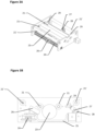
Figures 3A to 3C schematically represent different views of a cleaning module of a preferred embodiment of the present invention; -
Figure 4 schematically represent a view of a cleaning module of a preferred embodiment of the present invention. - The present detailed description is intended to illustrate the invention in a non-limitative manner since any feature of an embodiment may be combined with any other feature of a different embodiment in an advantageous manner.
-
Figures 1 and 2 show a general view of a first embodiment of the invention which is a wheel cleaning station. It has to be noted that although the present description focuses on wheels of wheelchair, the present invention may be adapted to any similar vehicles such as golf carts, strollers and the same. - The
wheel cleaning station 100 preferably comprises anactuation module 1, twocleaning modules 2, a cleaningliquid spraying module 3, adrying module 4 and awater extraction module 5. Additionally, thestation 100 may comprise a control andcommand module 6, possiblyramps 7 and a protection plate 8. - The
Actuation module 1 preferably contains the motors that drive the elements of thecleaning module 2 and is connected to the control andcommand module 6 which controls it. It also contains valves that open and shut the air streams and the water jets. - The cleaning station will be explained later after the wheel cleaning module. The wheel cleaning module is detailed in
figures 3A to 3C . - It comprises several bearings preferably having the form of
rollers 21,linear actuators 24 and at least onebrush 23. Preferably these elements are connected together via respective linkage connections. It also comprises asupport 25 shown infigure 3B and preferably having a bridge shape to facilitate its use and enhance its efficiency. - The
rollers 21, 21' are disposed in a parallel manner so as to bear or support a wheel to be cleaned and are controlled by theactivation unit 1 so as to permit rotation of the wheel. It is important here to note that therollers 21, 21' can function in different ways according to the type of vehicle coming to the station. For example, for a mechanical wheelchair which has free wheels, therollers 21, 21' are controlled so as to rotate and therefore drive in rotation the wheels with them. On the contrary, for a vehicle where the wheels are not free such as an electric wheelchair, therollers 21, 21' are controlled to be free such that it is the wheels of the wheelchair which can rotate by themselves and drive therollers 21, 21' without being hindered by any resistance. - In order to decide which mode is to be used, i.e. if the
rollers 21, 21' shall rotate to drive the wheels or be free to be rotated by the wheels, different options can be used. The choice can be actively made upfront by the user via a user interface on the control andcommand module 6 or via a telephone embedded application. Alternatively, the choice can be passively made via automatic recognition of the type of vehicle, this can be done through testing the resistance to turning the wheels, a camera and an AI software recognizing between an image of a mechanical wheelchair and an image of an electric wheelchair, or via a RFID tag embedded within the wheelchair detected by the cleaningstation 100, or the same. - According to a preferred embodiment, the
rollers 21, 21' are rotated together at the same velocity. The number ofrollers 21, 21' is not particularly limited. In the figures, one can see fourrollers 21, 21'. Ideally this permits that the twocentral rollers 21 are adapted to support and maintain stable small wheels (such as front wheels) while the twoexternal rollers 21" are adapted to support and stabilize and centralize larger wheels such as back wheels of wheelchairs. Additional rollers may be present to further enhance stabilization. Also, one can see that theinternal rollers 21 are lower (in height position) than the two external ones 21', this permits further improvement of stabilization since therollers 21, 21' are therefore preferably somehow located on a virtual circumference of the wheel to be cleaned. - According to a further embodiment, the height of the
rollers 21, 21' may be variable, by using springs or the same, so as to adapt themselves to the shape of a wheel incoming the system. - In addition to the
rollers 21, 21', thecleaning module 2 comprises abrush 23 that is controlled to either rotate counter-wise to the wheel or at a different speed than the wheel. The key feature here being that there is differential movement between thebrush 23 and the wheel thereby leading to friction between thebrush 23 and the wheel to permit a cleaning action of thebrush 23 onto the wheel. It is very preferable that thebrush 23 is disposed parallel to therollers 21, 21' so as to maximize the brushing efficiency. - In addition to these elements, the
cleaning module 2 comprises a movable support, preferably having the form of abridge 25, mounted on alinear actuation assembly 24 and adapted to move along the width of thecleaning module 2, preferably parallelly to therollers 21, 21' and thebrush 23 and therefore essentially perpendicular to the wheels or the vehicle direction. - The
movable bridge 25 is configured to at least support ascanning module 26 and a cleaningliquid spraying module 27. Optionally, it may also support adrying module 28. - The
liquid spraying module 27 is preferably at least one nozzle connected to a High-pressure water pump that feeds pressured water to it. The dryingmodule 28 is preferably at least one nozzle connected to a High-pressure air pump that feeds pressured air to it. According to an embodiment both modules my share the same nozzle. - The
scanning module 26 comprises at least twosensors 266, shown infigure 3C whish represent an upper view of thebridge 25, preferably three, which can be IR sensors, laser sensors, range finding sensors or the same and are adapted to detect the position and width of a wheel by detecting the lateral edges of this wheel. - According to a preferred embodiment depicted in
figure 3C and 4 , thewheel sensors 266 are disposed on one end of the bridge (here the entry/left end) and theliquid spraying module 27, and possibly the dryingmodule 28, is disposed on the other end (the exit/right end) so as to face each other. Thesensors 266 are placed on themodule 26 so as to be located on each side of theliquid spraying module 27 in the width direction of the module i.e. the moving direction of the bridge (represented by the arrows infigure 4 ). Although they could be placed on the same end of thebridge 25 as theliquid spraying module 27, the figures show them on the other side of thebridge 25. This permits to have athird sensor 266 which improves the accuracy of thecleaning module 2 and may act as a wheel detector and also permits to keep the sensors clean. During functioning, thebridge 25 executes a fast back and forth movement limited by the detection of the edge of the wheel. For example, when theleft sensor 266 detects the left lateral edge of the wheel (by not detecting the wheel anymore for example), thebridge 25 stops and is moved in the opposite direction until theright sensor 266 detects the right lateral edge of the wheel. The bridge is then stopped again and moved in the opposite direction. Since the liquid spraying module 27 (and preferably the drying module) is disposed between the twosensors 266, this ensures that it always faces the wheel's surface and continuously sprays the wheel without splashing the user or the wheelchair. - Regarding the drying
module 28, it should preferably be adapted to be able to dry both the wheel after cleaning but also the brush and/or the rollers between two cleaning sessions. For this reason, the cleaning module may comprise a drying nozzle orienting means which permits to control the orientation of thenozzle 28 of the drying module in direction of the wheel or the brush depending on the situation. - In the same manner, the module comprises
nozzle positioning modules 29 preferably disposed at one end of theLinear actuation assembly 24, and which is adapted to lower thenozzle 27 to position it to clean thebrush 23. At the other end it positions thenozzle 27 to position it to clean the wheel. - The cleaning
station 100 will be explained in more details. As explained above, it preferably comprises anactuation module 1, one ormore cleaning modules 2, a cleaningliquid spraying module 3, adrying module 4 and awater extraction module 5. Additionally, thestation 100 may comprise a control andcommand module 6, ramps 7 and possibly a protection plate 8. - The
Actuation module 1 preferably contains the motors that drive the elements of thecleaning module 2 and is connected to the control andcommand module 6 which controls it. - It has to be noted that the exact number of cleaning modules may vary depending on the type of vehicle for which it has to be used. For this reason, in the present embodiment depicted in
figures 1 and 2 , where we refer to a wheelchair, two modules are disposed parallelly so as to receive the left and right wheels of the wheelchair, respectively. Alternatively, three cleaning modules may be used in a "triangular" arrangement if it has to be used for a three wheeled vehicle with a single wheel in the front. - According to the preferred embodiment, the two modules are disposed parallelly next to each other with the
actuation module 1 in between in such a manner that each roller of the left module is linked to each roller of the right modules so as to rotate together. - The station also comprises a water extraction pump that extracts the water collected in the cleaning modules.
- The Control and
Command module 6 contains the electronics and power management. It features an interfacing panel with various inputs such as buttons. It features the interaction panel with a screen, a speaker and wireless communication. -
Optional Ramps 7 can be used to access the station, but these are obviously not needed if the station is disposed within the soil. Also, the protection plate 8 is preferably placed over the station to protect theactuation module 1. - Regarding the station and more particularly its size, it is chosen through the standards of wheelchairs. A standard maximum width of a wheelchair is 90 cm so as to be able to pass through an open door and the minimal width is 28 cm, therefore it is reasonable and preferable to have the module presenting a maximum width of 31 cm.
- While the embodiments have been described in conjunction with a number of embodiments, it is evident that many alternatives, modifications and variations would be or are apparent to those of ordinary skill in the applicable arts. Accordingly, this disclosure is intended to embrace all such alternatives, modifications, equivalents and variations that are within the scope of this disclosure. This for example particularly the case regarding the different apparatuses which can be used.
Claims (15)
- Wheel cleaning device (2) comprisinga wheel support module (21, 21') adapted to support said wheel in a rotative manner,a cleaning liquid spraying module (27) adapted to spray high pressure cleaning liquid onto a wheel's surface,characterized in that it further comprises a wheel scanning module (26) adapted to scan a surface of the wheel and determine the lateral edges of the wheel, anda control module adapted to control the cleaning liquid spraying module (27) based on the results of the wheel scanning module (26) so as to limit the cleaning liquid spraying zone within the detected lateral edges of the wheel so as to spray cleaning liquid exclusively onto the surface of the wheel.
- Device according to claim 1, characterized in that it further comprises a brushing module (23) adapted to brush said supported wheel.
- Device according to claim 2, characterized in that said brushing module (23) is a cylindrical brush (23) adapted to come in contact with the wheel and to be rotated in a direction different from the wheel rotation or in the same rotation direction but at a different speed.
- Device according to anyone of claims 1 to 3, characterized in that it further comprises a wheel detector adapted to automatically detect the presence of a wheel chosen from the group of an optical detector, a weight detector or similar.
- Device according to claim 4, characterized in that said wheel detector is said wheel scanning module.
- Device according to any one of claims 1 to 5, characterized in that it further comprises a wheel type identification module adapted to identify a wheel type and control the cleaning process accordingly.
- Device according to claim 6, characterized in that the wheel type identification module comprises an image capturing device and an AI software capable of identifying the type of wheel on the captured image and accordingly adapt the cleaning process.
- Device according to any one of claims 1 to 4, characterized in that the wheel support module (21, 21') comprises rollers (21, 21') disposed parallelly which are adapted to be rotated to drive the wheel in rotation or to be free to let the wheel rotate by itself.
- Device according to any one of claims 1 to 4, characterized in that the wheel support module (21, 21') comprises at least two pairs of rollers (21, 21') comprising a first internal pair (21) disposed a first height and adapted to support and maintain stable wheels presenting a first diameter and a second external pair (21') disposed at a second height and adapted to support and maintain stable wheels presenting a second diameter, wherein the second diameter is larger than the first diameter.
- Device according to any one of claims 1 to 6, characterized in that the wheel scanning module (26) comprises at least two sensors (266) positioned on each side of the cleaning liquid spraying module (27) in the width direction of the module.
- Device according to any one of claims 1 to 7, characterized in that it comprises a bridging element (25) mounted on a linear actuation assembly (24) and supporting the wheel scanning module (26) at one end and the cleaning liquid spraying module (27) at the other end configured to be moved back and forth along the width direction of the module (2).
- Device according to any one of claims 1 to 11, characterized in that it further comprises a drying module (28) adapted to spray high pressure air onto the wheel surface.
- Device according to any one of claims 1 to 12, characterized in that it the cleaning liquid spraying module (27) comprises at least one nozzle connected to a High-pressure water pump that feeds it the cleaning liquid.
- Device according to any one of claims 12 or 13, characterized in that it further comprises drying and/or spraying nozzle positioning modules (29) preferably disposed at the ends of the linear actuation assembly (24) and adapted to lower and/or raise the nozzle to position it to clean/dry the brush (23) or the wheel.
- Wheel cleaning station comprising a wheel cleaning device (2) of any one of claims 1-14.
Priority Applications (1)
| Application Number | Priority Date | Filing Date | Title |
|---|---|---|---|
| EP22168978.9A EP4265487A1 (en) | 2022-04-20 | 2022-04-20 | Wheel cleaning device |
Applications Claiming Priority (1)
| Application Number | Priority Date | Filing Date | Title |
|---|---|---|---|
| EP22168978.9A EP4265487A1 (en) | 2022-04-20 | 2022-04-20 | Wheel cleaning device |
Publications (1)
| Publication Number | Publication Date |
|---|---|
| EP4265487A1 true EP4265487A1 (en) | 2023-10-25 |
Family
ID=81344393
Family Applications (1)
| Application Number | Title | Priority Date | Filing Date |
|---|---|---|---|
| EP22168978.9A Withdrawn EP4265487A1 (en) | 2022-04-20 | 2022-04-20 | Wheel cleaning device |
Country Status (1)
| Country | Link |
|---|---|
| EP (1) | EP4265487A1 (en) |
Citations (3)
| Publication number | Priority date | Publication date | Assignee | Title |
|---|---|---|---|---|
| JP3048370U (en) | 1997-10-27 | 1998-05-06 | 有限会社サン・エンジニアリング | Wheelchair wheel cleaning equipment |
| JP2003164491A (en) * | 2001-09-20 | 2003-06-10 | Taisei Corp | Wheelchair wheel cleaning device |
| WO2019035784A2 (en) * | 2017-03-03 | 2019-02-21 | Mehmet Salih Atak | Automatic vehicle washing machine, brush block and brushing method |
-
2022
- 2022-04-20 EP EP22168978.9A patent/EP4265487A1/en not_active Withdrawn
Patent Citations (3)
| Publication number | Priority date | Publication date | Assignee | Title |
|---|---|---|---|---|
| JP3048370U (en) | 1997-10-27 | 1998-05-06 | 有限会社サン・エンジニアリング | Wheelchair wheel cleaning equipment |
| JP2003164491A (en) * | 2001-09-20 | 2003-06-10 | Taisei Corp | Wheelchair wheel cleaning device |
| WO2019035784A2 (en) * | 2017-03-03 | 2019-02-21 | Mehmet Salih Atak | Automatic vehicle washing machine, brush block and brushing method |
Similar Documents
| Publication | Publication Date | Title |
|---|---|---|
| US11880207B2 (en) | Pool cleaning system and method to automatically clean surfaces of a pool using images from a camera | |
| US12173524B2 (en) | Swimming pool cleaning system with image capture device | |
| RU2509520C2 (en) | Vacuum cleaner robot containing sensory handle | |
| US9658616B2 (en) | Cleaning robot and method for controlling the same | |
| KR100922506B1 (en) | Canister type automatic vacuum cleaner and system and method for vacuuming using same | |
| US20090314318A1 (en) | Floor washing robot | |
| KR101341197B1 (en) | An auto cleaner | |
| EP3323338B1 (en) | Cleaner and control method therefor | |
| CN105310605B (en) | Floor sweeper | |
| KR20010001624A (en) | Surface-travelling mobile apparatus and cleaning apparatus using the same | |
| KR20140145648A (en) | Cleaning robot and method for controlling the same | |
| CN109419455A (en) | Ground processing equipment with motor-driven floor treatment element | |
| CN109381134A (en) | Automatically the ground processing equipment to advance | |
| JP3345982B2 (en) | Mobile work robot | |
| EP3430960B1 (en) | Cleaner | |
| WO2023164204A1 (en) | Mobile cleaning robot suspension | |
| RU2619028C1 (en) | Floor-sweeping machine | |
| US11198218B1 (en) | Mobile robotic system and method | |
| KR102168080B1 (en) | Cleaning apparatus for plate glass | |
| KR102405510B1 (en) | Portable washing appratus for wheels of wheelchair | |
| JP2003052582A (en) | Cleaning equipment | |
| CN106269544A (en) | A kind of equipment for the classification of publilc baths slippers | |
| CN210749024U (en) | Cleaning turntable device with adjustable intelligence and cleaning robot | |
| EP1600095B1 (en) | Back EMF actuator control | |
| KR102311251B1 (en) | Robot Cleaner and Control method thereof |
Legal Events
| Date | Code | Title | Description |
|---|---|---|---|
| STAA | Information on the status of an ep patent application or granted ep patent |
Free format text: STATUS: THE APPLICATION HAS BEEN PUBLISHED |
|
| PUAI | Public reference made under article 153(3) epc to a published international application that has entered the european phase |
Free format text: ORIGINAL CODE: 0009012 |
|
| AK | Designated contracting states |
Kind code of ref document: A1 Designated state(s): AL AT BE BG CH CY CZ DE DK EE ES FI FR GB GR HR HU IE IS IT LI LT LU LV MC MK MT NL NO PL PT RO RS SE SI SK SM TR |
|
| STAA | Information on the status of an ep patent application or granted ep patent |
Free format text: STATUS: THE APPLICATION IS DEEMED TO BE WITHDRAWN |
|
| 18D | Application deemed to be withdrawn |
Effective date: 20240426 |