EP4265478B1 - Improved modular light bracket group and related mounting method - Google Patents
Improved modular light bracket group and related mounting method Download PDFInfo
- Publication number
- EP4265478B1 EP4265478B1 EP23162370.3A EP23162370A EP4265478B1 EP 4265478 B1 EP4265478 B1 EP 4265478B1 EP 23162370 A EP23162370 A EP 23162370A EP 4265478 B1 EP4265478 B1 EP 4265478B1
- Authority
- EP
- European Patent Office
- Prior art keywords
- bracket group
- light bracket
- central module
- module
- transverse
- Prior art date
- Legal status (The legal status is an assumption and is not a legal conclusion. Google has not performed a legal analysis and makes no representation as to the accuracy of the status listed.)
- Active
Links
Images






Classifications
-
- B—PERFORMING OPERATIONS; TRANSPORTING
- B60—VEHICLES IN GENERAL
- B60Q—ARRANGEMENT OF SIGNALLING OR LIGHTING DEVICES, THE MOUNTING OR SUPPORTING THEREOF OR CIRCUITS THEREFOR, FOR VEHICLES IN GENERAL
- B60Q1/00—Arrangement of optical signalling or lighting devices, the mounting or supporting thereof or circuits therefor
- B60Q1/26—Arrangement of optical signalling or lighting devices, the mounting or supporting thereof or circuits therefor the devices being primarily intended to indicate the vehicle, or parts thereof, or to give signals, to other traffic
- B60Q1/2619—Arrangement of optical signalling or lighting devices, the mounting or supporting thereof or circuits therefor the devices being primarily intended to indicate the vehicle, or parts thereof, or to give signals, to other traffic built in the vehicle body
- B60Q1/2649—Arrangement of optical signalling or lighting devices, the mounting or supporting thereof or circuits therefor the devices being primarily intended to indicate the vehicle, or parts thereof, or to give signals, to other traffic built in the vehicle body with provision for pre-mounting or temporary holding the device before or during final mounting
-
- B—PERFORMING OPERATIONS; TRANSPORTING
- B60—VEHICLES IN GENERAL
- B60Q—ARRANGEMENT OF SIGNALLING OR LIGHTING DEVICES, THE MOUNTING OR SUPPORTING THEREOF OR CIRCUITS THEREFOR, FOR VEHICLES IN GENERAL
- B60Q1/00—Arrangement of optical signalling or lighting devices, the mounting or supporting thereof or circuits therefor
- B60Q1/26—Arrangement of optical signalling or lighting devices, the mounting or supporting thereof or circuits therefor the devices being primarily intended to indicate the vehicle, or parts thereof, or to give signals, to other traffic
- B60Q1/30—Arrangement of optical signalling or lighting devices, the mounting or supporting thereof or circuits therefor the devices being primarily intended to indicate the vehicle, or parts thereof, or to give signals, to other traffic for indicating rear of vehicle, e.g. by means of reflecting surfaces
-
- B—PERFORMING OPERATIONS; TRANSPORTING
- B60—VEHICLES IN GENERAL
- B60Q—ARRANGEMENT OF SIGNALLING OR LIGHTING DEVICES, THE MOUNTING OR SUPPORTING THEREOF OR CIRCUITS THEREFOR, FOR VEHICLES IN GENERAL
- B60Q1/00—Arrangement of optical signalling or lighting devices, the mounting or supporting thereof or circuits therefor
- B60Q1/26—Arrangement of optical signalling or lighting devices, the mounting or supporting thereof or circuits therefor the devices being primarily intended to indicate the vehicle, or parts thereof, or to give signals, to other traffic
- B60Q1/30—Arrangement of optical signalling or lighting devices, the mounting or supporting thereof or circuits therefor the devices being primarily intended to indicate the vehicle, or parts thereof, or to give signals, to other traffic for indicating rear of vehicle, e.g. by means of reflecting surfaces
- B60Q1/305—Indicating devices for towed vehicles
-
- B—PERFORMING OPERATIONS; TRANSPORTING
- B60—VEHICLES IN GENERAL
- B60R—VEHICLES, VEHICLE FITTINGS, OR VEHICLE PARTS, NOT OTHERWISE PROVIDED FOR
- B60R13/00—Elements for body-finishing, identifying, or decorating; Arrangements or adaptations for advertising purposes
- B60R13/10—Registration, licensing, or like devices
- B60R13/105—Licence- or registration plates, provided with mounting means, e.g. frames, holders, retainers, brackets
-
- B—PERFORMING OPERATIONS; TRANSPORTING
- B60—VEHICLES IN GENERAL
- B60Q—ARRANGEMENT OF SIGNALLING OR LIGHTING DEVICES, THE MOUNTING OR SUPPORTING THEREOF OR CIRCUITS THEREFOR, FOR VEHICLES IN GENERAL
- B60Q1/00—Arrangement of optical signalling or lighting devices, the mounting or supporting thereof or circuits therefor
- B60Q1/26—Arrangement of optical signalling or lighting devices, the mounting or supporting thereof or circuits therefor the devices being primarily intended to indicate the vehicle, or parts thereof, or to give signals, to other traffic
- B60Q1/56—Arrangement of optical signalling or lighting devices, the mounting or supporting thereof or circuits therefor the devices being primarily intended to indicate the vehicle, or parts thereof, or to give signals, to other traffic for illuminating registrations or the like, e.g. for licence plates
-
- B—PERFORMING OPERATIONS; TRANSPORTING
- B60—VEHICLES IN GENERAL
- B60Q—ARRANGEMENT OF SIGNALLING OR LIGHTING DEVICES, THE MOUNTING OR SUPPORTING THEREOF OR CIRCUITS THEREFOR, FOR VEHICLES IN GENERAL
- B60Q2800/00—Features related to particular types of vehicles not otherwise provided for
- B60Q2800/20—Utility vehicles, e.g. for agriculture, construction work
Definitions
- the present invention relates to an improved light bracket group, in particular for industrial vehicles such as trucks, lorries, trailers, vans, and the like, and the related mounting method.
- Said light bracket groups comprise both the supports of the rear lights of the vehicle, usually arranged at the side ends of the group so as to integrate the position, braking and direction signalling functions, while having the vehicle plate with related lighting devices in the central position.
- Such known solutions can be in one piece, i.e., consisting of a single module which is fixed to the chassis of the vehicle by specific support brackets.
- Solutions of light bracket groups in several parts are also known, in particular a central structural portion supporting the plate and the related lighting devices, and two side portions, each supporting the rear lights with position, braking, and direction signalling functions.
- the known solutions are not modular and adjustable given that they provide for making specific sizes of side portions which are fixed to the central portion in a unique, non-adjustable manner. This means that, in any case, in order to change the size of the light bracket, different sizes, i.e., widths, of the central portion and/or the side portions need to be made, typically by moulding. Solutions according to cited prior art are disclosed, for example, by FR 2735733 A1 .
- reference numeral 4 indicates as a whole an overall view of a light bracket group for industrial vehicles.
- the light bracket group 4 comprises a pair of side modules 8, 12 having a main transverse extension X-X; each of said side modules 8, 12 supports at least one light 16 having signalling and/or lighting functions of the industrial vehicle.
- the light can comprise a direction indicator, a position light, a stop light, a reverse light, a side-marker, and the like.
- the light bracket group 4 further comprises a central module 20 arranged in an intermediate and contiguous position with respect to said side modules 8, 12.
- the central module 20 supports at least one identification plate of the industrial vehicle and preferably a lighting device 24 of said plate. Moreover, the central module 20 can also support further lighting and/or signalling lights and covers thereof.
- Each side module 8, 12 is provided with fixing means (not shown) to a chassis of the industrial vehicle, in particular to a bracket of said chassis.
- Said fixing means typically comprise screws, bolts, and the like.
- the central module 20 in turn is fixed to the side modules 8, 12 by removable fixing means 28. Therefore, the central module 20 is not fixed to the chassis of the industrial vehicle, rather it is hooked and fixed to the side modules 8, 12, as better specified below.
- the side modules 8, 12, at inner transverse ends 32, 36 facing the central module 20, have, with respect to a section plane perpendicular to said main transverse extension X-X, a body 40 with a "C"-shaped section having a vertical stretch 44 and two side edges 48 substantially perpendicular to the vertical stretch 44.
- the side edges 48 have raised profiles 52 which form transverse sliding rails for corresponding transverse seats 56 of the central module 20.
- said transverse seats 56 of the central module 20 are configured to achieve a shape coupling with said raised profiles 52 of the side edges 48.
- the central module 20 with respect to a section plane perpendicular to the main transverse extension X-X, comprises a "C"-shaped section having a vertical element 60 and a pair of horizontal branches 64 delimiting said transverse seats 56.
- said horizontal branches 64 of the central module 20 end with hooking appendages 68 configured to form a hook with free ends of the side edges 48 of the inner transverse ends 32, 36 of the side modules 8, 12.
- the inner transverse ends 32, 36 of the side modules 8, 12 are constrained with undercuts between the hooking appendages 68 and the transverse seats 56 of the central module 20.
- the vertical element 60 of the central module 20 comprises stiffening ribs 76 at a rear face 80 thereof.
- said stiffening ribs 76 are arranged along directions mutually crossed and angled with respect to the main transverse extension X-X.
- the removable fixing means 28 can comprise screws or pins engaged in slotted holes 84 parallel to said main transverse extension X-X.
- said screws or pins comprise elastically expandable heads or portions.
- each side module 8, 12 is fixed to the rear chassis of the industrial vehicle.
- each side module 8, 12 it is possible to fix each side module 8, 12 to a rear chassis of the industrial vehicle, this being followed by associating the central module 20 in an intermediate position between the side modules 8, 12 and fixing it to the inner transverse ends 32, 36 of said side modules 8, 12.
- Such a method provides for an elastically deformation of the central module 20 until it can be hooked at the back on the inner transverse ends 32, 36 of the side modules 8, 12, with particular reference to the hooking appendages 68.
- first side module 8 it is possible to fix a first side module 8 to a rear chassis of the industrial vehicle and associate the central module 20 with a first inner transverse end 32 of said first side module 8; this being followed by the step of fixing a second side module 12 to the rear chassis of the industrial vehicle and associating it, at a second transverse end 36 thereof, with said central module 20.
- the present invention allows overcoming the drawbacks presented in the prior art.
- the present invention allows obtaining the modularity of the components forming the light bracket group, which can thus be adapted to any transverse size of the industrial vehicle.
- the side modules do not vibrate and do not make noise when travelling, given that they are directly fixed to the chassis of the industrial vehicle.
- the central module which normally has the greater extension within the group, has no structural features that make it compact, and generally the entire light bracket group is significantly lighter than the solutions of the prior art.
- the mounting of the light bracket group is also practical and quick.
- the solution further allows replacing individual modules due to breaks, for example, or even disassembling individual modules for maintenance operations, for example.
Landscapes
- Engineering & Computer Science (AREA)
- Mechanical Engineering (AREA)
- Lighting Device Outwards From Vehicle And Optical Signal (AREA)
Description
- The present invention relates to an improved light bracket group, in particular for industrial vehicles such as trucks, lorries, trailers, vans, and the like, and the related mounting method.
- There are several solutions of light bracket groups in the prior art, which are mounted to the rear part of industrial vehicles, such as trucks, lorries, trailers, vans, and the like.
- Said light bracket groups comprise both the supports of the rear lights of the vehicle, usually arranged at the side ends of the group so as to integrate the position, braking and direction signalling functions, while having the vehicle plate with related lighting devices in the central position.
- Such known solutions can be in one piece, i.e., consisting of a single module which is fixed to the chassis of the vehicle by specific support brackets.
- Such a solution results in certain disadvantages given that it requires manufacturing a single module by moulding in one piece. This is complex to obtain in terms of the mould and is also expensive because it includes preparing a custom-made mould for every possible size of the light bracket group. Indeed, the industrial vehicles mentioned can have different transverse widths, therefore a mould for each width needs to be provided.
- Moreover, in case of even partial breaking of the group, said known single-piece solutions result in the need to replace the entire group.
- Moreover, such single-piece solutions require to disassemble the entire group from the vehicle chassis also in case of maintenance.
- Solutions of light bracket groups in several parts are also known, in particular a central structural portion supporting the plate and the related lighting devices, and two side portions, each supporting the rear lights with position, braking, and direction signalling functions.
- The aforesaid solutions are not free from drawbacks and limitations.
- In particular, such solutions provide for the central structural portion to be sturdy, and thus heavy, while the side portions are relatively lightweight and flexible.
- This cause the group to be heavy overall and the side portions, being lighter and cantilevered, tend to vibrate significantly during the travel of the vehicle. In addition to causing bothersome noises, such vibrations can result in the formation of cracks and breaks in the long run.
- Moreover, the known solutions are not modular and adjustable given that they provide for making specific sizes of side portions which are fixed to the central portion in a unique, non-adjustable manner. This means that, in any case, in order to change the size of the light bracket, different sizes, i.e., widths, of the central portion and/or the side portions need to be made, typically by moulding. Solutions according to cited prior art are disclosed, for example, by
FR 2735733 A1 - Therefore, the need is felt to solve the drawbacks and limitations mentioned with reference to the prior art.
- Such a need is met by a light bracket group according to claim 1 and by methods for mounting a light bracket group according to claims 9, 10 and 11.
- Further features and advantages of the present invention will become more comprehensible from the following description of preferred embodiments thereof, given by way of non-limiting examples, in which:
-
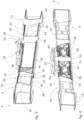
Figure 1 is a front view, in an assembled configuration, of a light bracket group according to an embodiment of the present invention; -
Figure 2 is a rear view of the light bracket group inFigure 1 ; -
Figure 3 is a front view, in an exploded configuration, of the light bracket group inFigure 1 ; -
Figure 4 is a rear view, in an exploded configuration, of the light bracket group inFigure 1 ; -
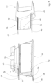
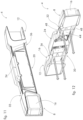
Figures 5-9 are enlarged perspective views of details of the light bracket group inFigure 1 ; -
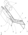
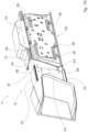
Figures 10-12 are perspective views of a possible mounting sequence of a light bracket group according to an embodiment of the present invention; -
Figures 13-15 are perspective views of a further possible mounting sequence of a light bracket group according to an embodiment of the present invention; -
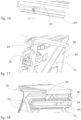
Figures 16-19 are perspective views of details of a light bracket group according to an embodiment of the present invention. - The elements or parts of elements common to the embodiments described below will be indicated by the same reference numerals.
- With reference to the aforesaid figures,
reference numeral 4 indicates as a whole an overall view of a light bracket group for industrial vehicles. - The
light bracket group 4 comprises a pair ofside modules side modules light 16 having signalling and/or lighting functions of the industrial vehicle. By way of example, the light can comprise a direction indicator, a position light, a stop light, a reverse light, a side-marker, and the like. - The
light bracket group 4 further comprises acentral module 20 arranged in an intermediate and contiguous position with respect to saidside modules - The
central module 20 supports at least one identification plate of the industrial vehicle and preferably alighting device 24 of said plate. Moreover, thecentral module 20 can also support further lighting and/or signalling lights and covers thereof. - Each
side module - Said fixing means typically comprise screws, bolts, and the like.
- The
central module 20 in turn is fixed to theside modules central module 20 is not fixed to the chassis of the industrial vehicle, rather it is hooked and fixed to theside modules - According to the invention, the
side modules transverse ends central module 20, have, with respect to a section plane perpendicular to said main transverse extension X-X, abody 40 with a "C"-shaped section having avertical stretch 44 and twoside edges 48 substantially perpendicular to thevertical stretch 44. - The
side edges 48 have raisedprofiles 52 which form transverse sliding rails for correspondingtransverse seats 56 of thecentral module 20. - According to a possible embodiment, said
transverse seats 56 of thecentral module 20 are configured to achieve a shape coupling with said raisedprofiles 52 of theside edges 48. - According to the invention, the
central module 20, with respect to a section plane perpendicular to the main transverse extension X-X, comprises a "C"-shaped section having avertical element 60 and a pair ofhorizontal branches 64 delimiting saidtransverse seats 56. - According to the invention, said
horizontal branches 64 of thecentral module 20 end withhooking appendages 68 configured to form a hook with free ends of theside edges 48 of the innertransverse ends side modules - The possible vibrations of the
central module 20 that, as seen, is not directly fixed to the chassis of the industrial vehicle, are also eliminated by virtue of such a hook coupling between the free ends of theside edges 48 of the innertransverse ends side modules hooking appendages 68. - According to a possible embodiment, the
central module 20, between thevertical element 60 and saidhooking appendages 68, delimits avolume 72 adapted to house said innertransverse ends side modules - According to a possible embodiment, in the assembly configuration, the inner
transverse ends side modules hooking appendages 68 and thetransverse seats 56 of thecentral module 20. - According to a possible embodiment, the
vertical element 60 of thecentral module 20 comprisesstiffening ribs 76 at arear face 80 thereof. - For example, said
stiffening ribs 76 are arranged along directions mutually crossed and angled with respect to the main transverse extension X-X. - The removable fixing means 28 can comprise screws or pins engaged in slotted
holes 84 parallel to said main transverse extension X-X. - According to a possible embodiment, said screws or pins comprise elastically expandable heads or portions.
- The method for mounting a light bracket group according to the present invention will now be described.
- In particular, according to a possible embodiment (
Figures 10-12 ), it is possible to associate thecentral module 20 with and fix it between saidside modules light bracket group 4. - Therefore, each
side module - According to a possible embodiment (
Figures 13-15 ), it is possible to fix eachside module central module 20 in an intermediate position between theside modules transverse ends side modules central module 20 until it can be hooked at the back on the innertransverse ends side modules hooking appendages 68. - According to a possible embodiment, it is possible to fix a
first side module 8 to a rear chassis of the industrial vehicle and associate thecentral module 20 with a first innertransverse end 32 of saidfirst side module 8; this being followed by the step of fixing asecond side module 12 to the rear chassis of the industrial vehicle and associating it, at a secondtransverse end 36 thereof, with saidcentral module 20. - As can be appreciated from the above description, the present invention allows overcoming the drawbacks presented in the prior art.
- In particular, the present invention allows obtaining the modularity of the components forming the light bracket group, which can thus be adapted to any transverse size of the industrial vehicle.
- Moreover, the side modules do not vibrate and do not make noise when travelling, given that they are directly fixed to the chassis of the industrial vehicle.
- The central module, which normally has the greater extension within the group, has no structural features that make it compact, and generally the entire light bracket group is significantly lighter than the solutions of the prior art.
- The mounting of the light bracket group is also practical and quick. The solution further allows replacing individual modules due to breaks, for example, or even disassembling individual modules for maintenance operations, for example.
- In order to meet contingent, specific needs, those skilled in the art may make several changes and variations to the solutions described above.
- The scope of protection of the invention is defined by the following claims.
Claims (11)
- Light bracket group (4) for industrial vehicles, comprising:- a pair of side modules (8,12), having a main transverse extension (X-X), said side modules (8,12) supporting at least one light having signalling and/or lighting functions of the industrial vehicle,- a central module (20) arranged in an intermediate and contiguous position with respect to said side modules (8,12), the central module (20) supporting at least one identification plate of the industrial vehicle,- wherein each side module (8,12) is provided with fixing means to a chassis of the industrial vehicle,- wherein the central module (20) is fixed to the side modules (8,12) by removable fixing means (28),wherein the side modules (8,12), at the inner transverse ends (32,36), facing the central module (20), have, with respect to a section plane perpendicular to said main transverse extension (X-X), a body (40) with a "C" section having a vertical stretch (44) and two side edges (48), substantially perpendicular to the vertical stretch (44), said side edges (48) having raised profiles (52) which create transverse sliding rails for corresponding transverse seats (56) of the central module (20),characterized in thatthe central module (20), with respect to a section plane perpendicular to the main transverse extension (X-X), comprises a "C" section having a vertical element (60) and a pair of horizontal branches (64) which delimit said transverse seats (56),wherein, with respect to a section plane perpendicular to the main transverse extension (X-X), said horizontal branches (64) of the central module (20) end with hooking appendages (68), configured to create a hook with free ends of the side edges (48) of the inner transverse ends (32,36) of the side modules (8,12).
- Light bracket group (4) for industrial vehicles according to claim 1, wherein said transverse seats (56) of the central module (20) are configured to create a shape coupling with said raised profiles (52).
- Light bracket group (4) for industrial vehicles according to any one of previous claims, wherein the central module (20), between the vertical element (60) and said hooking appendages (68), delimits a volume (72) adapted to house said inner transverse ends (32,36) of the side modules (8,12).
- Light bracket group (4) for industrial vehicles according to claim 1, 2 or 3, wherein, in the assembly configuration, the inner transverse ends (32,36) of the side modules (8,12) are constrained with undercuts between the hooking appendages (68) and the transverse seats (56) of the central module (20).
- Light bracket group (4) for industrial vehicles according to any one of claims 1 to 4, wherein a vertical element (60) of the central module (20) comprises stiffening ribs (76), at a rear face thereof.
- Light bracket group (4) for industrial vehicles according to claim 5, wherein said stiffening ribs (76) are arranged along directions crossed and angled with each other with respect to the main transverse extension (X-X).
- Light bracket group (4) for industrial vehicles according to any one of claims 1 to 6, wherein the removable fixing means (28) comprise screws or pins which engage in slotted holes (84) that are parallel to said main transverse extension (X-X).
- Light bracket group (4) for industrial vehicles according to claim 7, wherein said screws or pins comprise elastically expandable heads or portions.
- Method for mounting a light bracket group (4) for industrial vehicles, comprising the steps of:- preparing a light bracket group (4) according to any one of claims 1 to 8,- associating and fixing the central module (20) between said side modules (8,12) in advance so as to adjust the overall transverse width of the light bracket group (4),- fixing each side module (8,12) to a rear chassis of the industrial vehicle.
- Method for mounting a light bracket group (4) for industrial vehicles, comprising the steps of:- preparing a light bracket group (4) according to any one of claims 1 to 8,- fixing each side module (8,12) to a rear chassis of the industrial vehicle,- associating the central module (20) in an intermediate position between the side modules (8,12) and fixing it to the inner transverse ends (32,36) of said side modules (8,12) .
- Method for mounting a light bracket group (4) for industrial vehicles, comprising the steps of:- preparing a light bracket group (4) according to any one of claims 1 to 8,- fixing a first side module (8) to a rear chassis of the industrial vehicle,- associating the central module (20) to a first inner transverse end (32) of said first side module (8),- fixing a second side module (12) to a rear chassis of the industrial vehicle and associating it, at a second transverse end (36) thereof, to said central module (20).
Applications Claiming Priority (1)
| Application Number | Priority Date | Filing Date | Title |
|---|---|---|---|
| IT102022000007709A IT202200007709A1 (en) | 2022-04-19 | 2022-04-19 | IMPROVED MODULAR HEADLIGHT ASSEMBLY AND RELATED ASSEMBLY METHOD |
Publications (2)
| Publication Number | Publication Date |
|---|---|
| EP4265478A1 EP4265478A1 (en) | 2023-10-25 |
| EP4265478B1 true EP4265478B1 (en) | 2024-12-04 |
Family
ID=82385537
Family Applications (1)
| Application Number | Title | Priority Date | Filing Date |
|---|---|---|---|
| EP23162370.3A Active EP4265478B1 (en) | 2022-04-19 | 2023-03-16 | Improved modular light bracket group and related mounting method |
Country Status (3)
| Country | Link |
|---|---|
| EP (1) | EP4265478B1 (en) |
| IT (1) | IT202200007709A1 (en) |
| PL (1) | PL4265478T3 (en) |
Family Cites Families (4)
| Publication number | Priority date | Publication date | Assignee | Title |
|---|---|---|---|---|
| US3083292A (en) * | 1961-01-27 | 1963-03-26 | Charles A Roe | Trailer light support |
| FR2735733B1 (en) * | 1995-06-22 | 1997-09-05 | Bernard Michel | REMOVABLE AND FOLDABLE LIGHT CARRIER FOR TRAILER |
| NL1001182C2 (en) * | 1995-09-13 | 1997-03-20 | Felua Groep | Lighting fixture for a vehicle. |
| ITTV20100043U1 (en) * | 2010-09-21 | 2012-03-22 | Lago Accessori S R L | REAR BUMPER STRUCTURE FOR VEHICLES |
-
2022
- 2022-04-19 IT IT102022000007709A patent/IT202200007709A1/en unknown
-
2023
- 2023-03-16 EP EP23162370.3A patent/EP4265478B1/en active Active
- 2023-03-16 PL PL23162370.3T patent/PL4265478T3/en unknown
Also Published As
| Publication number | Publication date |
|---|---|
| IT202200007709A1 (en) | 2023-10-19 |
| EP4265478A1 (en) | 2023-10-25 |
| PL4265478T3 (en) | 2025-04-28 |
Similar Documents
| Publication | Publication Date | Title |
|---|---|---|
| US10821903B2 (en) | Modular rail and step system | |
| CN202053950U (en) | Motor vehicle and external rearview mirror for motor vehicle | |
| US7644966B2 (en) | Vehicle bumper fascia retainer | |
| US20110006553A1 (en) | Winch Carrier and Grille Guard Mounting System | |
| JP3740124B2 (en) | Convertible passenger car body and modular unit | |
| US8184847B2 (en) | Vehicle speaker mounting system | |
| US11358520B2 (en) | Vehicle taillight assembly | |
| CN103661676A (en) | Positioning and reinforcement structure for a vehicle | |
| DE60220252D1 (en) | FRONT ARRANGEMENT FOR HEAVY-COMMERCIAL VEHICLES | |
| EP4265478B1 (en) | Improved modular light bracket group and related mounting method | |
| US10914448B2 (en) | Vehicle lamp installation method and assembly | |
| US20240375600A1 (en) | Bumper with selectively attachable light bars | |
| JPH06503776A (en) | Suspension spring mount on vehicle body | |
| US20050110245A1 (en) | Instrument panel adapter for airbag mount | |
| CN115743014B (en) | Front protection skin assembly, front bumper assembly and vehicle | |
| EP0604237A1 (en) | Vehicle bumper mounting | |
| JP2003127811A (en) | Mounting structure of radiator grille | |
| CN107792192A (en) | Side members and the vehicle with side members | |
| JPH0270915A (en) | front part of car | |
| JPH03213472A (en) | Front car body structure for automobile and assembling method thereof | |
| JP2002096760A (en) | Vehicle front-end module device | |
| US20260001502A1 (en) | Front bumper assembly | |
| US11001321B2 (en) | Apparatus for supporting a component mounting plate between trailer beams | |
| US20210016714A1 (en) | Running Board | |
| KR100380052B1 (en) | Integrated beam structure for vehicles |
Legal Events
| Date | Code | Title | Description |
|---|---|---|---|
| STAA | Information on the status of an ep patent application or granted ep patent |
Free format text: STATUS: THE APPLICATION HAS BEEN PUBLISHED |
|
| PUAI | Public reference made under article 153(3) epc to a published international application that has entered the european phase |
Free format text: ORIGINAL CODE: 0009012 |
|
| AK | Designated contracting states |
Kind code of ref document: A1 Designated state(s): AL AT BE BG CH CY CZ DE DK EE ES FI FR GB GR HR HU IE IS IT LI LT LU LV MC ME MK MT NL NO PL PT RO RS SE SI SK SM TR |
|
| P01 | Opt-out of the competence of the unified patent court (upc) registered |
Effective date: 20231213 |
|
| STAA | Information on the status of an ep patent application or granted ep patent |
Free format text: STATUS: REQUEST FOR EXAMINATION WAS MADE |
|
| 17P | Request for examination filed |
Effective date: 20240321 |
|
| RBV | Designated contracting states (corrected) |
Designated state(s): AL AT BE BG CH CY CZ DE DK EE ES FI FR GB GR HR HU IE IS IT LI LT LU LV MC ME MK MT NL NO PL PT RO RS SE SI SK SM TR |
|
| GRAP | Despatch of communication of intention to grant a patent |
Free format text: ORIGINAL CODE: EPIDOSNIGR1 |
|
| STAA | Information on the status of an ep patent application or granted ep patent |
Free format text: STATUS: GRANT OF PATENT IS INTENDED |
|
| INTG | Intention to grant announced |
Effective date: 20240724 |
|
| GRAS | Grant fee paid |
Free format text: ORIGINAL CODE: EPIDOSNIGR3 |
|
| GRAA | (expected) grant |
Free format text: ORIGINAL CODE: 0009210 |
|
| STAA | Information on the status of an ep patent application or granted ep patent |
Free format text: STATUS: THE PATENT HAS BEEN GRANTED |
|
| AK | Designated contracting states |
Kind code of ref document: B1 Designated state(s): AL AT BE BG CH CY CZ DE DK EE ES FI FR GB GR HR HU IE IS IT LI LT LU LV MC ME MK MT NL NO PL PT RO RS SE SI SK SM TR |
|
| REG | Reference to a national code |
Ref country code: CH Ref legal event code: EP |
|
| REG | Reference to a national code |
Ref country code: DE Ref legal event code: R096 Ref document number: 602023001213 Country of ref document: DE |
|
| REG | Reference to a national code |
Ref country code: IE Ref legal event code: FG4D |
|
| REG | Reference to a national code |
Ref country code: NL Ref legal event code: FP |
|
| REG | Reference to a national code |
Ref country code: LT Ref legal event code: MG9D |
|
| PG25 | Lapsed in a contracting state [announced via postgrant information from national office to epo] |
Ref country code: HR Free format text: LAPSE BECAUSE OF FAILURE TO SUBMIT A TRANSLATION OF THE DESCRIPTION OR TO PAY THE FEE WITHIN THE PRESCRIBED TIME-LIMIT Effective date: 20241204 |
|
| PG25 | Lapsed in a contracting state [announced via postgrant information from national office to epo] |
Ref country code: FI Free format text: LAPSE BECAUSE OF FAILURE TO SUBMIT A TRANSLATION OF THE DESCRIPTION OR TO PAY THE FEE WITHIN THE PRESCRIBED TIME-LIMIT Effective date: 20241204 |
|
| PG25 | Lapsed in a contracting state [announced via postgrant information from national office to epo] |
Ref country code: BG Free format text: LAPSE BECAUSE OF FAILURE TO SUBMIT A TRANSLATION OF THE DESCRIPTION OR TO PAY THE FEE WITHIN THE PRESCRIBED TIME-LIMIT Effective date: 20241204 |
|
| PG25 | Lapsed in a contracting state [announced via postgrant information from national office to epo] |
Ref country code: ES Free format text: LAPSE BECAUSE OF FAILURE TO SUBMIT A TRANSLATION OF THE DESCRIPTION OR TO PAY THE FEE WITHIN THE PRESCRIBED TIME-LIMIT Effective date: 20241204 |
|
| PG25 | Lapsed in a contracting state [announced via postgrant information from national office to epo] |
Ref country code: NO Free format text: LAPSE BECAUSE OF FAILURE TO SUBMIT A TRANSLATION OF THE DESCRIPTION OR TO PAY THE FEE WITHIN THE PRESCRIBED TIME-LIMIT Effective date: 20250304 |
|
| PG25 | Lapsed in a contracting state [announced via postgrant information from national office to epo] |
Ref country code: GR Free format text: LAPSE BECAUSE OF FAILURE TO SUBMIT A TRANSLATION OF THE DESCRIPTION OR TO PAY THE FEE WITHIN THE PRESCRIBED TIME-LIMIT Effective date: 20250305 Ref country code: LV Free format text: LAPSE BECAUSE OF FAILURE TO SUBMIT A TRANSLATION OF THE DESCRIPTION OR TO PAY THE FEE WITHIN THE PRESCRIBED TIME-LIMIT Effective date: 20241204 |
|
| PG25 | Lapsed in a contracting state [announced via postgrant information from national office to epo] |
Ref country code: RS Free format text: LAPSE BECAUSE OF FAILURE TO SUBMIT A TRANSLATION OF THE DESCRIPTION OR TO PAY THE FEE WITHIN THE PRESCRIBED TIME-LIMIT Effective date: 20250304 |
|
| REG | Reference to a national code |
Ref country code: AT Ref legal event code: MK05 Ref document number: 1747844 Country of ref document: AT Kind code of ref document: T Effective date: 20241204 |
|
| PG25 | Lapsed in a contracting state [announced via postgrant information from national office to epo] |
Ref country code: SM Free format text: LAPSE BECAUSE OF FAILURE TO SUBMIT A TRANSLATION OF THE DESCRIPTION OR TO PAY THE FEE WITHIN THE PRESCRIBED TIME-LIMIT Effective date: 20241204 |
|
| PG25 | Lapsed in a contracting state [announced via postgrant information from national office to epo] |
Ref country code: IS Free format text: LAPSE BECAUSE OF FAILURE TO SUBMIT A TRANSLATION OF THE DESCRIPTION OR TO PAY THE FEE WITHIN THE PRESCRIBED TIME-LIMIT Effective date: 20250404 |
|
| PGFP | Annual fee paid to national office [announced via postgrant information from national office to epo] |
Ref country code: IT Payment date: 20250331 Year of fee payment: 3 |
|
| PG25 | Lapsed in a contracting state [announced via postgrant information from national office to epo] |
Ref country code: PT Free format text: LAPSE BECAUSE OF FAILURE TO SUBMIT A TRANSLATION OF THE DESCRIPTION OR TO PAY THE FEE WITHIN THE PRESCRIBED TIME-LIMIT Effective date: 20250404 |
|
| PG25 | Lapsed in a contracting state [announced via postgrant information from national office to epo] |
Ref country code: EE Free format text: LAPSE BECAUSE OF FAILURE TO SUBMIT A TRANSLATION OF THE DESCRIPTION OR TO PAY THE FEE WITHIN THE PRESCRIBED TIME-LIMIT Effective date: 20241204 |
|
| PG25 | Lapsed in a contracting state [announced via postgrant information from national office to epo] |
Ref country code: AT Free format text: LAPSE BECAUSE OF FAILURE TO SUBMIT A TRANSLATION OF THE DESCRIPTION OR TO PAY THE FEE WITHIN THE PRESCRIBED TIME-LIMIT Effective date: 20241204 Ref country code: RO Free format text: LAPSE BECAUSE OF FAILURE TO SUBMIT A TRANSLATION OF THE DESCRIPTION OR TO PAY THE FEE WITHIN THE PRESCRIBED TIME-LIMIT Effective date: 20241204 |
|
| PG25 | Lapsed in a contracting state [announced via postgrant information from national office to epo] |
Ref country code: SK Free format text: LAPSE BECAUSE OF FAILURE TO SUBMIT A TRANSLATION OF THE DESCRIPTION OR TO PAY THE FEE WITHIN THE PRESCRIBED TIME-LIMIT Effective date: 20241204 |
|
| PG25 | Lapsed in a contracting state [announced via postgrant information from national office to epo] |
Ref country code: CZ Free format text: LAPSE BECAUSE OF FAILURE TO SUBMIT A TRANSLATION OF THE DESCRIPTION OR TO PAY THE FEE WITHIN THE PRESCRIBED TIME-LIMIT Effective date: 20241204 |
|
| REG | Reference to a national code |
Ref country code: DE Ref legal event code: R097 Ref document number: 602023001213 Country of ref document: DE |
|
| PG25 | Lapsed in a contracting state [announced via postgrant information from national office to epo] |
Ref country code: SE Free format text: LAPSE BECAUSE OF FAILURE TO SUBMIT A TRANSLATION OF THE DESCRIPTION OR TO PAY THE FEE WITHIN THE PRESCRIBED TIME-LIMIT Effective date: 20241204 |
|
| PG25 | Lapsed in a contracting state [announced via postgrant information from national office to epo] |
Ref country code: DK Free format text: LAPSE BECAUSE OF FAILURE TO SUBMIT A TRANSLATION OF THE DESCRIPTION OR TO PAY THE FEE WITHIN THE PRESCRIBED TIME-LIMIT Effective date: 20241204 |
|
| PLBE | No opposition filed within time limit |
Free format text: ORIGINAL CODE: 0009261 |
|
| STAA | Information on the status of an ep patent application or granted ep patent |
Free format text: STATUS: NO OPPOSITION FILED WITHIN TIME LIMIT |
|
| PG25 | Lapsed in a contracting state [announced via postgrant information from national office to epo] |
Ref country code: MC Free format text: LAPSE BECAUSE OF FAILURE TO SUBMIT A TRANSLATION OF THE DESCRIPTION OR TO PAY THE FEE WITHIN THE PRESCRIBED TIME-LIMIT Effective date: 20241204 |
|
| 26N | No opposition filed |
Effective date: 20250905 |
|
| PG25 | Lapsed in a contracting state [announced via postgrant information from national office to epo] |
Ref country code: LU Free format text: LAPSE BECAUSE OF NON-PAYMENT OF DUE FEES Effective date: 20250316 |
|
| PG25 | Lapsed in a contracting state [announced via postgrant information from national office to epo] |
Ref country code: FR Free format text: LAPSE BECAUSE OF NON-PAYMENT OF DUE FEES Effective date: 20250331 |
|
| PG25 | Lapsed in a contracting state [announced via postgrant information from national office to epo] |
Ref country code: IE Free format text: LAPSE BECAUSE OF NON-PAYMENT OF DUE FEES Effective date: 20250316 |
|
| PGFP | Annual fee paid to national office [announced via postgrant information from national office to epo] |
Ref country code: DE Payment date: 20260325 Year of fee payment: 4 |
|
| PGFP | Annual fee paid to national office [announced via postgrant information from national office to epo] |
Ref country code: BE Payment date: 20260319 Year of fee payment: 4 |
|
| PGFP | Annual fee paid to national office [announced via postgrant information from national office to epo] |
Ref country code: NL Payment date: 20260323 Year of fee payment: 4 |
|
| PGFP | Annual fee paid to national office [announced via postgrant information from national office to epo] |
Ref country code: PL Payment date: 20260303 Year of fee payment: 4 |