EP4265474A1 - Position-sensitive controller for aircraft seating - Google Patents
Position-sensitive controller for aircraft seating Download PDFInfo
- Publication number
- EP4265474A1 EP4265474A1 EP23164584.7A EP23164584A EP4265474A1 EP 4265474 A1 EP4265474 A1 EP 4265474A1 EP 23164584 A EP23164584 A EP 23164584A EP 4265474 A1 EP4265474 A1 EP 4265474A1
- Authority
- EP
- European Patent Office
- Prior art keywords
- orientation
- seat
- interface device
- continuously
- passenger
- Prior art date
- Legal status (The legal status is an assumption and is not a legal conclusion. Google has not performed a legal analysis and makes no representation as to the accuracy of the status listed.)
- Pending
Links
- 238000009877 rendering Methods 0.000 claims description 12
- 238000002347 injection Methods 0.000 claims description 7
- 239000007924 injection Substances 0.000 claims description 7
- 238000000034 method Methods 0.000 claims description 5
- 230000003213 activating effect Effects 0.000 claims 1
- 230000007613 environmental effect Effects 0.000 description 9
- 230000008901 benefit Effects 0.000 description 4
- 238000010276 construction Methods 0.000 description 2
- 238000010586 diagram Methods 0.000 description 2
- 239000011521 glass Substances 0.000 description 2
- 238000013500 data storage Methods 0.000 description 1
- 230000003247 decreasing effect Effects 0.000 description 1
- 238000001514 detection method Methods 0.000 description 1
- 230000010354 integration Effects 0.000 description 1
- 239000000463 material Substances 0.000 description 1
- 239000002991 molded plastic Substances 0.000 description 1
- 229920000642 polymer Polymers 0.000 description 1
- 239000000243 solution Substances 0.000 description 1
- 230000003068 static effect Effects 0.000 description 1
- 230000000007 visual effect Effects 0.000 description 1
Images


Classifications
-
- B—PERFORMING OPERATIONS; TRANSPORTING
- B64—AIRCRAFT; AVIATION; COSMONAUTICS
- B64D—EQUIPMENT FOR FITTING IN OR TO AIRCRAFT; FLIGHT SUITS; PARACHUTES; ARRANGEMENTS OR MOUNTING OF POWER PLANTS OR PROPULSION TRANSMISSIONS IN AIRCRAFT
- B64D11/00—Passenger or crew accommodation; Flight-deck installations not otherwise provided for
- B64D11/06—Arrangements of seats, or adaptations or details specially adapted for aircraft seats
- B64D11/0639—Arrangements of seats, or adaptations or details specially adapted for aircraft seats with features for adjustment or converting of seats
- B64D11/06395—Arrangements of seats, or adaptations or details specially adapted for aircraft seats with features for adjustment or converting of seats characterised by the arrangement of electric motors for adjustment
-
- B—PERFORMING OPERATIONS; TRANSPORTING
- B64—AIRCRAFT; AVIATION; COSMONAUTICS
- B64D—EQUIPMENT FOR FITTING IN OR TO AIRCRAFT; FLIGHT SUITS; PARACHUTES; ARRANGEMENTS OR MOUNTING OF POWER PLANTS OR PROPULSION TRANSMISSIONS IN AIRCRAFT
- B64D11/00—Passenger or crew accommodation; Flight-deck installations not otherwise provided for
- B64D11/06—Arrangements of seats, or adaptations or details specially adapted for aircraft seats
- B64D11/0639—Arrangements of seats, or adaptations or details specially adapted for aircraft seats with features for adjustment or converting of seats
- B64D11/064—Adjustable inclination or position of seats
-
- B—PERFORMING OPERATIONS; TRANSPORTING
- B60—VEHICLES IN GENERAL
- B60N—SEATS SPECIALLY ADAPTED FOR VEHICLES; VEHICLE PASSENGER ACCOMMODATION NOT OTHERWISE PROVIDED FOR
- B60N2/00—Seats specially adapted for vehicles; Arrangement or mounting of seats in vehicles
- B60N2/02—Seats specially adapted for vehicles; Arrangement or mounting of seats in vehicles the seat or part thereof being movable, e.g. adjustable
- B60N2/0224—Non-manual adjustments, e.g. with electrical operation
- B60N2/0226—User interfaces specially adapted for seat adjustment
- B60N2/0233—Touchscreens
-
- B—PERFORMING OPERATIONS; TRANSPORTING
- B60—VEHICLES IN GENERAL
- B60N—SEATS SPECIALLY ADAPTED FOR VEHICLES; VEHICLE PASSENGER ACCOMMODATION NOT OTHERWISE PROVIDED FOR
- B60N2/00—Seats specially adapted for vehicles; Arrangement or mounting of seats in vehicles
- B60N2/24—Seats specially adapted for vehicles; Arrangement or mounting of seats in vehicles for particular purposes or particular vehicles
- B60N2/32—Seats specially adapted for vehicles; Arrangement or mounting of seats in vehicles for particular purposes or particular vehicles convertible for other use
- B60N2/34—Seats specially adapted for vehicles; Arrangement or mounting of seats in vehicles for particular purposes or particular vehicles convertible for other use into a bed
Definitions
- Seat controllers are static and disposed in a compromise ergonomic position based on features such as the average passenger size, and seat recline. Some seats use tethered controls to allow for flexible usage. Some seats incorporate multiple separate controls such as a remote PCU to accommodate large passenger position differences (e.g. bed mode).
- a remote PCU to accommodate large passenger position differences (e.g. bed mode).
- Existing seat controller solutions are primarily limited to flat surfaces. It would be advantageous to have a seat controller that were conveniently useable in a wide variety of applications.
- embodiments of the inventive concepts disclosed herein are directed to an aircraft seat pod with a reclining seat and a controller interface that extends around a surface of the pod, include a surface obscured by the seat when in an upright position.
- the controller tracks the position and orientation of the seat and displays seat controls on the interface at a convenient location.
- more than one interface is disposed at different locations to conveniently accommodate passengers of different size or in different orientations.
- Vision sensors may track the position and orientation of a passenger and preemptively display controls at a convenient location.
- inventive concepts are not limited in their application to the details of construction and the arrangement of the components or steps or methodologies set forth in the following description or illustrated in the drawings.
- inventive concepts disclosed herein may be practiced without these specific details.
- well-known features may not be described in detail to avoid unnecessarily complicating the instant disclosure.
- inventive concepts disclosed herein are capable of other embodiments or of being practiced or carried out in various ways. Also, it is to be understood that the phraseology and terminology employed herein is for the purpose of description and should not be regarded as limiting.
- a letter following a reference numeral is intended to reference an embodiment of the feature or element that may be similar, but not necessarily identical, to a previously described element or feature bearing the same reference numeral (e.g., 1, 1a, 1b).
- reference numeral e.g. 1, 1a, 1b
- Such shorthand notations are used for purposes of convenience only, and should not be construed to limit the inventive concepts disclosed herein in any way unless expressly stated to the contrary.
- any reference to "one embodiment,” or “some embodiments” means that a particular element, feature, structure, or characteristic described in connection with the embodiment is included in at least one embodiment of the inventive concepts disclosed herein.
- the appearances of the phrase “in some embodiments” in various places in the specification are not necessarily all referring to the same embodiment, and embodiments of the inventive concepts disclosed may include one or more of the features expressly described or inherently present herein, or any combination of sub-combination of two or more such features, along with any other features which may not necessarily be expressly described or inherently present in the instant disclosure.
- embodiments of the inventive concepts disclosed herein are directed to an aircraft seat pod with a reclining seat and a controller interface that extends around a surface of the pod, include a surface obscured by the seat when in an upright position.
- the controller tracks the position and orientation of the seat and displays seat controls on the interface at a convenient location. More than one interface may be disposed at different locations to conveniently accommodate passengers of different size or in different orientations.
- Vision sensors may track the position and orientation of a passenger and preemptively display controls at a convenient location.
- the system includes a processor 100, memory 102 connected to the processor 100 for embodying processor executable code, and an interface 104.
- the interface 104 may comprise a touch sensitive display configured to render controls and receive control inputs at any point along the interface 104. Alternatively, or in addition, the interface 104 may be proximity sensing for hand gesturing or motion detection.
- the display aspect of the interface 104 may include feedback features separate from, or in addition to, rendered images; for example, haptic feedback and / or illuminated visual cues.
- the interface 104 defines a primary region including seat controls and a secondary region comprising areas without seta control.
- the processor 100 may re-render the primary region focused on the detected input.
- the processor 100 is connected to one or more motors 110 and / or actuators to control aspects of a reclining seat or other elements of an aircraft pod.
- the processor 100 may determine, based on the disposition of the motors 110 or actuators, a current position and / orientation of a reclining seat or other controllable features in the pod. Based on the determined position and orientation, the processor 100 may identify a desirable location for controls on the interface 104, and re-render the controls in that location by default.
- the processor 100 may identify a first contact on the interface 104 corresponding to a control input to a rendered control; while the passenger continues to contact the interface, but the point of contact is shifting (for example, due to the movement of the corresponding reclining seat), the processor 100 may continuously re-render the control on the interface 104 such that a current point of contact always corresponds to the control input of the first contact.
- the processor 100 is connected to one or more sensors 106, including vision sensors, and configured to identify a position and / or orientation of a passenger, and render controls on the interface 104 at a location corresponding to that position and / or orientation. For example, when a reclining seat is in a fully reclined mode, the passenger may be lying down and facing either to the passenger's left or right. Sensor's 106 may use head tacking and / or eye tracking algorithms to determine a location of the interface 104 to render controls.
- the processor 100 may store specific passenger preferences in a data storage element 108.
- the processor 100 may store a passenger selected default location for a particular orientation of the reclinable aircraft seat.
- the interface 104 comprises electronic components embedded in injection molded components of an aircraft seating area.
- a polymer injection molded panel may include a display element where the display element electronics are disposed within the injection molded panel.
- a touch sensitive glass element may be placed over the display element, or a glass or molded plastic element with a capacitive film disposed on an outward facing surface.
- the electronic components may follow the curvature of the injection molded panel.
- FIG. 2 an environmental view of a position sensitive interface according to an exemplary embodiment is shown.
- a reclinable aircraft seat 200 or other features, are controllable via an interface 202, 204
- the relative position of a passenger to the interface may change as the reclinable aircraft seat 200 reclines.
- the interface 202, 204 includes a first interface segment 202 that is generally accessible, and a second interface segment 204 that is obscured while the reclinable aircraft seat 200 is in an upright orientation.
- the second interface segment 204 When the reclinable aircraft seat 200 is reclined, the second interface segment 204 becomes accessible. In at least one embodiment, the second interface segment 204 may wrap around a curved surface proximal to the reclinable aircraft seat 200.
- a controller in data communication with the interface 202, 204 may determine the orientation of the reclinable aircraft seat 200 with reference to motors or actuators in data communication with the controller, or with reference to one or more vision sensors.
- a controller continuously adjusts a rendering location of controls on the interface 202, 204 according to the continuously changing orientation of the reclinable aircraft seat 200, potentially weighted by stored passenger preference locations, so that the rendered controls are always in a convenient location for the passenger. It may be appreciated that a convenient location for the passenger may be based on the passenger's size, reduced passenger mobility, etc.
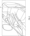
- FIG. 3 an environmental view of a position sensitive interface according to an exemplary embodiment is shown.
- multiple interfaces 302, 304 may be disposed on surfaces near a reclinable aircraft seat 300.
- Each interface 302, 304 is configured via processor to render seat controls at various locations on the interfaces 302, 304 based on the disposition and orientation of the reclinable aircraft seat 300, passenger preference, etc.
- each interface 302, 304 may be configured and disposed to render specific sets of controls at separate locations based on unique factors or preferences specific to such controls.
- a first interface 302 may be dedicated to a first set of actuators or features of the reclinable aircraft seat 300 such as a back cushion and headrest
- a second interface 304 may be dedicated to a second set of actuators or features of the reclinable aircraft seat 300 such as a bottom cushion and footrest.
- the disposition of the rendered controls on the interfaces 302, 304 are separately determined based on the orientation of the corresponding actuators or features, or by passenger preference, included a previously recorded default preference.
- controls may be rendered to keep them within convenient reach of the passenger no matter how the reclinable aircraft seat 300 is oriented.
- controls may be separately rendered to maintain some dispositional relationship to the portions of the reclinable aircraft seat 300 they control.
- Embedded electronics may enable integration of interfaces 302, 304 with 3D electronic HMI surfaces in areas not previously practical.
- Embedded electronic components integrate circuits into injection molded components.
- one or more interfaces 402 are disposed to render controls for actuators or features of a reclinable aircraft seat 400.
- the interface 402 may provide controls for the orientation of other features of the seating area or pod such a passenger light or air flow gasper 404.
- a processor configured to render controls at various locations on the interface 402, is also configured to control actuators connected to the other features. Based on the disposition of reclinable aircraft seat 400, the processor maintains those other features in orientations that may be generally convenient for the passenger, such as keeping a reading light focused on a portion of the reclinable aircraft seat 400 as the reclinable aircraft seat 400 shifts from an upright to a reclined orientation.
- orientation control of the other features may be relative to a passenger selection.
- the passenger may manipulate the orientation of an air flow gasper 404 via the interface 402.
- the orientation of the air flow gasper 402 may be automatically adjusted according to an algorithm to keep the air flow gasper 404 pointed toward the passenger selected potion of the reclinable aircraft seat 400.
- the force of the airflow may be automatically adjusted to account for an increasing or decreasing distance between the reclinable aircraft seat 400 and the air flow gasper 404.
- the interface 402 and corresponding processor may control audio and video components within the pod.
- the processor may adjust aspects of the audio and video components according to the orientation of the reclinable aircraft seat 400.
- a reclinable aircraft seat 500 may lay completely flat and a passenger 502 on their side might face either left or right while lying down.
- one or more interfaces 504, 506 may be disposed around the reclinable aircraft seat 500 such that at least one interface 504, 506 is disposed on either side of the passenger.
- a single interface 504, 506 may continuously wrap around the reclinable aircraft seat 500.
- one or more vision sensors 508, 510 may be disposed around the reclinable aircraft seat 500.
- a processor controlling the disposition of controls on the one or more interfaces 504, 506 may identify which direction the passenger 502 is facing based on data from the vision sensors 508, 510.
- the processor may employ head tracking or eye tracking algorithms to determine which direction the passenger 502 is facing.
- the processor may further utilize eye tracking to render controls at a location corresponding to the line of sight of the passenger 502.
- Embodiments of the present disclosure enable adjustable seating based on the preferred ergonomics of the passenger and accommodate mobility-disadvantaged passengers. Furthermore, embodiments may be utilized anywhere that a passenger interface needs to accommodate various ergonomics and / or passenger location.
Abstract
An aircraft seat pod with a reclining seat includes a controller interface that extends around a surface of the pod, include a surface obscured by the seat when in an upright position. The controller tracks the position and orientation of the seat and displays seat controls on the interface at a convenient location. More than one interface may be disposed at different locations to conveniently accommodate passengers of different size or in different orientations. Vision sensors may track the position and orientation of a passenger and preemptively display controls at a convenient location.
Description
- Seat controllers are static and disposed in a compromise ergonomic position based on features such as the average passenger size, and seat recline. Some seats use tethered controls to allow for flexible usage. Some seats incorporate multiple separate controls such as a remote PCU to accommodate large passenger position differences (e.g. bed mode). Existing seat controller solutions are primarily limited to flat surfaces. It would be advantageous to have a seat controller that were conveniently useable in a wide variety of applications.
- In one aspect, embodiments of the inventive concepts disclosed herein are directed to an aircraft seat pod with a reclining seat and a controller interface that extends around a surface of the pod, include a surface obscured by the seat when in an upright position. The controller tracks the position and orientation of the seat and displays seat controls on the interface at a convenient location.
- In a further aspect, more than one interface is disposed at different locations to conveniently accommodate passengers of different size or in different orientations. Vision sensors may track the position and orientation of a passenger and preemptively display controls at a convenient location.
- It is to be understood that both the foregoing general description and the following detailed description are exemplary and explanatory only and should not restrict the scope of the claims. The accompanying drawings, which are incorporated in and constitute a part of the specification, illustrate exemplary embodiments of the inventive concepts disclosed herein and together with the general description, serve to explain the principles.
- The numerous advantages of the embodiments of the inventive concepts disclosed herein may be better understood by those skilled in the art by reference to the accompanying figures in which:
- FIG. 1
- shows a block diagram of a system for implementing a position sensitive interface according to an exemplary embodiment;
- FIG. 2
- shows an environmental view of a position sensitive interface according to an exemplary embodiment;
- FIG. 3
- shows an environmental view of a position sensitive interface according to an exemplary embodiment;
- FIG. 4
- shows an environmental view of a position sensitive interface according to an exemplary embodiment;
- FIG. 5A
- shows an environmental view of a position sensitive interface according to an exemplary embodiment;
- FIG. 5B
- shows an environmental view of a position sensitive interface according to an exemplary embodiment;
- Before explaining at least one embodiment of the inventive concepts disclosed herein in detail, it is to be understood that the inventive concepts are not limited in their application to the details of construction and the arrangement of the components or steps or methodologies set forth in the following description or illustrated in the drawings. In the following detailed description of embodiments of the instant inventive concepts, numerous specific details are set forth in order to provide a more thorough understanding of the inventive concepts. However, it will be apparent to one of ordinary skill in the art having the benefit of the instant disclosure that the inventive concepts disclosed herein may be practiced without these specific details. In other instances, well-known features may not be described in detail to avoid unnecessarily complicating the instant disclosure. The inventive concepts disclosed herein are capable of other embodiments or of being practiced or carried out in various ways. Also, it is to be understood that the phraseology and terminology employed herein is for the purpose of description and should not be regarded as limiting.
- As used herein a letter following a reference numeral is intended to reference an embodiment of the feature or element that may be similar, but not necessarily identical, to a previously described element or feature bearing the same reference numeral (e.g., 1, 1a, 1b). Such shorthand notations are used for purposes of convenience only, and should not be construed to limit the inventive concepts disclosed herein in any way unless expressly stated to the contrary.
- Further, unless expressly stated to the contrary, "or" refers to an inclusive or and not to an exclusive or. For example, a condition A or B is satisfied by anyone of the following: A is true (or present) and B is false (or not present), A is false (or not present) and B is true (or present), and both A and B are true (or present).
- In addition, use of the "a" or "an" are employed to describe elements and components of embodiments of the instant inventive concepts. This is done merely for convenience and to give a general sense of the inventive concepts, and "a" and "an" are intended to include one or at least one and the singular also includes the plural unless it is obvious that it is meant otherwise.
- Also, while various components may be depicted as being connected directly, direct connection is not a requirement. Components may be in data communication with intervening components that are not illustrated or described.
- Finally, as used herein any reference to "one embodiment," or "some embodiments" means that a particular element, feature, structure, or characteristic described in connection with the embodiment is included in at least one embodiment of the inventive concepts disclosed herein. The appearances of the phrase "in some embodiments" in various places in the specification are not necessarily all referring to the same embodiment, and embodiments of the inventive concepts disclosed may include one or more of the features expressly described or inherently present herein, or any combination of sub-combination of two or more such features, along with any other features which may not necessarily be expressly described or inherently present in the instant disclosure.
- Broadly, embodiments of the inventive concepts disclosed herein are directed to an aircraft seat pod with a reclining seat and a controller interface that extends around a surface of the pod, include a surface obscured by the seat when in an upright position. The controller tracks the position and orientation of the seat and displays seat controls on the interface at a convenient location. More than one interface may be disposed at different locations to conveniently accommodate passengers of different size or in different orientations. Vision sensors may track the position and orientation of a passenger and preemptively display controls at a convenient location.
- Referring to
FIG. 1 , a block diagram of a system for implementing a position sensitive interface according to an exemplary embodiment is shown. The system includes aprocessor 100,memory 102 connected to theprocessor 100 for embodying processor executable code, and aninterface 104. Theinterface 104 may comprise a touch sensitive display configured to render controls and receive control inputs at any point along theinterface 104. Alternatively, or in addition, theinterface 104 may be proximity sensing for hand gesturing or motion detection. Furthermore, the display aspect of theinterface 104 may include feedback features separate from, or in addition to, rendered images; for example, haptic feedback and / or illuminated visual cues. - In at least one embodiment, the
interface 104 defines a primary region including seat controls and a secondary region comprising areas without seta control. When an input is detected in the secondary region, theprocessor 100 may re-render the primary region focused on the detected input. - In at least one embodiment, the
processor 100 is connected to one ormore motors 110 and / or actuators to control aspects of a reclining seat or other elements of an aircraft pod. Theprocessor 100 may determine, based on the disposition of themotors 110 or actuators, a current position and / orientation of a reclining seat or other controllable features in the pod. Based on the determined position and orientation, theprocessor 100 may identify a desirable location for controls on theinterface 104, and re-render the controls in that location by default. Alternatively, or in addition, theprocessor 100 may identify a first contact on theinterface 104 corresponding to a control input to a rendered control; while the passenger continues to contact the interface, but the point of contact is shifting (for example, due to the movement of the corresponding reclining seat), theprocessor 100 may continuously re-render the control on theinterface 104 such that a current point of contact always corresponds to the control input of the first contact. - In at least one embodiment, the
processor 100 is connected to one ormore sensors 106, including vision sensors, and configured to identify a position and / or orientation of a passenger, and render controls on theinterface 104 at a location corresponding to that position and / or orientation. For example, when a reclining seat is in a fully reclined mode, the passenger may be lying down and facing either to the passenger's left or right. Sensor's 106 may use head tacking and / or eye tracking algorithms to determine a location of theinterface 104 to render controls. - In at least one embodiment, the
processor 100 may store specific passenger preferences in adata storage element 108. For example, theprocessor 100 may store a passenger selected default location for a particular orientation of the reclinable aircraft seat. - In at least one embodiment, the
interface 104 comprises electronic components embedded in injection molded components of an aircraft seating area. For example, a polymer injection molded panel may include a display element where the display element electronics are disposed within the injection molded panel. A touch sensitive glass element may be placed over the display element, or a glass or molded plastic element with a capacitive film disposed on an outward facing surface. The electronic components may follow the curvature of the injection molded panel. - Referring to
FIG. 2 , an environmental view of a position sensitive interface according to an exemplary embodiment is shown. Where areclinable aircraft seat 200, or other features, are controllable via aninterface reclinable aircraft seat 200 reclines. In at least one embodiment, theinterface first interface segment 202 that is generally accessible, and asecond interface segment 204 that is obscured while thereclinable aircraft seat 200 is in an upright orientation. - When the
reclinable aircraft seat 200 is reclined, thesecond interface segment 204 becomes accessible. In at least one embodiment, thesecond interface segment 204 may wrap around a curved surface proximal to thereclinable aircraft seat 200. A controller in data communication with theinterface reclinable aircraft seat 200 with reference to motors or actuators in data communication with the controller, or with reference to one or more vision sensors. - In at least one embodiment, a controller continuously adjusts a rendering location of controls on the
interface reclinable aircraft seat 200, potentially weighted by stored passenger preference locations, so that the rendered controls are always in a convenient location for the passenger. It may be appreciated that a convenient location for the passenger may be based on the passenger's size, reduced passenger mobility, etc. - Referring to
FIG. 3 , an environmental view of a position sensitive interface according to an exemplary embodiment is shown. In at least one embodiment,multiple interfaces reclinable aircraft seat 300. Eachinterface interfaces reclinable aircraft seat 300, passenger preference, etc. - In at least one embodiment, each
interface first interface 302 may be dedicated to a first set of actuators or features of thereclinable aircraft seat 300 such as a back cushion and headrest, while asecond interface 304 may be dedicated to a second set of actuators or features of thereclinable aircraft seat 300 such as a bottom cushion and footrest. - In at least one embodiment, the disposition of the rendered controls on the
interfaces reclinable aircraft seat 300 is oriented. Alternatively, controls may be separately rendered to maintain some dispositional relationship to the portions of thereclinable aircraft seat 300 they control. - Embedded electronics may enable integration of
interfaces - Referring to
FIG. 4 , an environmental view of a position sensitive interface according to an exemplary embodiment is shown. In at least one embodiment, one ormore interfaces 402 are disposed to render controls for actuators or features of areclinable aircraft seat 400. In addition to the controls for thereclinable aircraft seat 400, theinterface 402 may provide controls for the orientation of other features of the seating area or pod such a passenger light orair flow gasper 404. - In at least one embodiment, a processor, configured to render controls at various locations on the
interface 402, is also configured to control actuators connected to the other features. Based on the disposition ofreclinable aircraft seat 400, the processor maintains those other features in orientations that may be generally convenient for the passenger, such as keeping a reading light focused on a portion of thereclinable aircraft seat 400 as thereclinable aircraft seat 400 shifts from an upright to a reclined orientation. - In at least one embodiment, orientation control of the other features may be relative to a passenger selection. For example, the passenger may manipulate the orientation of an
air flow gasper 404 via theinterface 402. Then, as thereclinable aircraft seat 400 shifts from an upright to a reclined orientation, the orientation of theair flow gasper 402 may be automatically adjusted according to an algorithm to keep theair flow gasper 404 pointed toward the passenger selected potion of thereclinable aircraft seat 400. Furthermore, the force of the airflow may be automatically adjusted to account for an increasing or decreasing distance between thereclinable aircraft seat 400 and theair flow gasper 404. - In at least one embodiment, where the
interface 402 and corresponding processor may control audio and video components within the pod. The processor may adjust aspects of the audio and video components according to the orientation of thereclinable aircraft seat 400. - Referring to
FIGS. 5A-5B , environmental views of a position sensitive interface according to an exemplary embodiment are shown. In at least one embodiment, areclinable aircraft seat 500 may lay completely flat and apassenger 502 on their side might face either left or right while lying down. In a pod or semi enclosed seating area, one ormore interfaces 504, 506 may be disposed around thereclinable aircraft seat 500 such that at least oneinterface 504, 506 is disposed on either side of the passenger. Alternatively, asingle interface 504, 506 may continuously wrap around thereclinable aircraft seat 500. - In at least one embodiment, one or
more vision sensors reclinable aircraft seat 500. A processor controlling the disposition of controls on the one ormore interfaces 504, 506 may identify which direction thepassenger 502 is facing based on data from thevision sensors passenger 502 is facing. In at least one embodiment, the processor may further utilize eye tracking to render controls at a location corresponding to the line of sight of thepassenger 502. - Embodiments of the present disclosure enable adjustable seating based on the preferred ergonomics of the passenger and accommodate mobility-disadvantaged passengers. Furthermore, embodiments may be utilized anywhere that a passenger interface needs to accommodate various ergonomics and / or passenger location.
- It is believed that the inventive concepts disclosed herein and many of their attendant advantages will be understood by the foregoing description of embodiments of the inventive concepts disclosed, and it will be apparent that various changes may be made in the form, construction, and arrangement of the components thereof without departing from the broad scope of the inventive concepts disclosed herein or without sacrificing all of their material advantages; and individual features from various embodiments may be combined to arrive at other embodiments. The form herein before described being merely an explanatory embodiment thereof, it is the intention of the following claims to encompass and include such changes. Furthermore, any of the features disclosed in relation to any of the individual embodiments may be incorporated into any other embodiment.
Claims (15)
- A seat control device comprising:one or more motors (110);at least one touch sensitive interface device; andat least one processor (100) in data communication with the one or more motors (110), the at least one interface device, and a memory storing processor executable code for configuring the at least one processor (100) to:render a set of input controls on the interface device;receive an input from the interface device;activate at least one of the one or more motors (110); andcontinuously re-render the input controls at different locations on the interface device.
- The seat control device of Claim 1, wherein:the at least one processor (100) is further configured to continuously determine a seat orientation and passenger orientation;continuously re-rendering the input controls at different locations on the interface device comprises relating the different locations on the touch sensitive interface to one or more of the determined seat orientation and passenger orientation.
- The seat control device of Claim 2, wherein continuously determining the seat orientation comprises tracking a current state of each of the one or more motors (110) and relating each current state to a seat orientation, and/ or further comprising one or more vision-based sensors, wherein continuously determining the seat orientation comprises:receiving image data from the one or more vision-based sensors;identifying one or more landmarks disposed on the seat; anddetermining the seat orientation based on a location of each of the one or more landmarks.
- The seat control device of Claim 3, wherein:the at least one interface device comprises a first interface device disposed on a first surface and a second interface device disposed on a second surface;the first surface is disposed on an opposite of the seat as compared to the second surface;the at least one processor (100) is further configured to:receive image data from the one or more vision sensors;determine an orientation of a passenger in the seat; anddetermine if the passenger is more closely facing the first surface or the second surface; andcontinuously re-rendering the input controls comprises rendering the input controls on the first touch sensitive interface or the second touch sensitive interface based on the determination that the passenger is more closely facing the first surface or the second surface.
- The seat control device of any preceding Claim, wherein:at least one of the one or more motors (110) is configured to control an orientation of an air flow gasper; andthe at least one processor (100) is further configured to continuously adjust the at least one motor configured to control the orientation of the air flow gasper based on a defined relationship between the orientation of the air flow gasper and a seat orientation, and/or wherein:at least one of the one or more motors (110) is configured to control an orientation of a light; andthe at least one processor (100) is further configured to continuously adjust the at least one motor configured to control the orientation of the light based on a defined relationship between the orientation of the light and a seat orientation.
- A method comprising:rendering a set of input controls on at least one interface device;receiving an input from the interface device;activating one or more motors (110);continuously tracking a current location of an uninterrupted contact with the interface device;continuously re-rendering the input controls at different locations on the interface device based on the current location of the uninterrupted contact with the interface device to maintain a relative position between the input controls and the current location.
- The method of Claim 6, wherein:further comprising continuously determining a seat orientation,wherein continuously re-rendering the input controls at different locations on the interface device comprises relating the different locations on the touch sensitive interface to the determined seat orientation.
- The method of Claim 7, wherein continuously determining the seat orientation comprises tracking a current state of each of the one or more motors (110) and relating each current state to a seat orientation, and/or further comprising receiving image data from one or more vision-based sensors, wherein continuously determining the seat orientation comprises:identifying one or more landmarks disposed on a seat; anddetermining the seat orientation based on a location of each of the one or more landmarks.
- The method of Claim 8, wherein:the at least one interface device comprises a first interface device disposed on a first surface and a second interface device disposed on a second surface;the first surface is disposed on an opposite side of the seat as compared to the second surface;further comprising:receiving motion or proximity data from one or more motion or proximity sensors corresponding to a movement or proximity of a passenger;receiving image data from the one or more vision sensors;determining an orientation of the passenger in the seat based on one or more of the image data and motion or proximity data; anddetermining if the passenger is more closely facing the first surface or the second surface; andwherein continuously re-rendering the input controls comprises rendering the input controls on the first touch sensitive interface or the second touch sensitive interface based on the determination that the passenger is more closely facing the first surface or the second surface.
- An aircraft seat pod comprising:one or more injection molded panels;a reclinable seat;a plurality of motors (110), at least one motor configured to control an orientation of the reclinable seat;at least one interface device; andat least one processor (100) in data communication with the plurality of motors (110), the at least one interface device, and a memory storing processor executable code for configuring the at least one processor (100) to:render a set of input controls on the interface device;receive an input from the interface device;activate at least one of the plurality of motors (110); andcontinuously re-render the input controls at different locations on the interface device,wherein the at least one interface device is embedded in one of the one or more injection molded panels.
- The aircraft seat pod of Claim 10, wherein:the at least one processor (100) is further configured to continuously determine an orientation of the reclinable seat;continuously re-rendering the input controls at different locations on the interface device comprises relating the different locations on the touch sensitive interface to the determined reclinable seat orientation.
- The aircraft seat pod of Claim 11, wherein continuously determining the orientation of the reclinable seat comprises tracking a current state of each of the plurality of motors (110) and relating each current state to the orientation of the reclinable seat, and/or further comprising one or more vision-based sensors, wherein continuously determining the orientation of the reclinable seat comprises:receiving image data from the one or more vision-based sensors;identifying one or more landmarks disposed on the reclinable seat; anddetermining the orientation of the reclinable seat based on a location of each of the one or more landmarks.
- The aircraft seat pod of Claim 12, wherein:the at least one interface device comprises a first interface device disposed on a first surface and a second interface device disposed on a second surface;the first surface is disposed on an opposite of the reclinable seat as compared to the second surface;the at least one processor (100) is further configured to:receiving image data from the one or more vision sensors;determine an orientation of a passenger in the reclinable seat; anddetermine if the passenger is more closely facing the first surface or the second surface; andcontinuously re-rendering the input controls comprises rendering the input controls on the first touch sensitive interface or the second touch sensitive interface based on the determination that the passenger is more closely facing the first surface or the second surface.
- The aircraft seat pod of Claim 13, further comprising at least one air flow gasper,
wherein:at least one of the plurality of motors (110) is configured to control an orientation of the air flow gasper; andthe at least one processor (100) is further configured to continuously adjust the at least one motor configured to control the orientation of the air flow gasper based on a defined relationship between the orientation of the air flow gasper and an orientation of the reclinable seat, and/or. further comprising at least one light:wherein:at least one of the plurality of motors (110) is configured to control an orientation of the light; andthe at least one processor (100) is further configured to continuously adjust the at least one motor configured to control the orientation of the light based on a defined relationship between the orientation of the light and an orientation of the reclinable seat. - The aircraft seat pod of Claim 14, further comprising at least one air flow gasper,
wherein:at least one of the plurality of motors (110) is configured to control an orientation of the air flow gasper; andthe at least one processor (100) is further configured to continuously adjust the at least one motor configured to control the orientation of the air flow gasper and light based on a defined relationship between the orientation of the air flow gasper, light, and the orientation of the reclinable seat.
Applications Claiming Priority (1)
| Application Number | Priority Date | Filing Date | Title |
|---|---|---|---|
| US17/725,717 US20230339614A1 (en) | 2022-04-21 | 2022-04-21 | Position-sensitive controller for aircraft seating |
Publications (1)
| Publication Number | Publication Date |
|---|---|
| EP4265474A1 true EP4265474A1 (en) | 2023-10-25 |
Family
ID=85778871
Family Applications (1)
| Application Number | Title | Priority Date | Filing Date |
|---|---|---|---|
| EP23164584.7A Pending EP4265474A1 (en) | 2022-04-21 | 2023-03-28 | Position-sensitive controller for aircraft seating |
Country Status (2)
| Country | Link |
|---|---|
| US (1) | US20230339614A1 (en) |
| EP (1) | EP4265474A1 (en) |
Citations (3)
| Publication number | Priority date | Publication date | Assignee | Title |
|---|---|---|---|---|
| GB2496452A (en) * | 2011-11-14 | 2013-05-15 | Almec Eas Ltd | Aircraft seat with position and condition sensors |
| US20150137492A1 (en) * | 2013-11-20 | 2015-05-21 | Ford Global Technologies, Llc | Multi-stage airbag in vehicle with reconfigurable |
| CN108583373A (en) * | 2018-04-16 | 2018-09-28 | 石家庄国辰知识产权服务有限公司 | A kind of sound-controlled electric seat for electric vehicle field |
-
2022
- 2022-04-21 US US17/725,717 patent/US20230339614A1/en active Pending
-
2023
- 2023-03-28 EP EP23164584.7A patent/EP4265474A1/en active Pending
Patent Citations (3)
| Publication number | Priority date | Publication date | Assignee | Title |
|---|---|---|---|---|
| GB2496452A (en) * | 2011-11-14 | 2013-05-15 | Almec Eas Ltd | Aircraft seat with position and condition sensors |
| US20150137492A1 (en) * | 2013-11-20 | 2015-05-21 | Ford Global Technologies, Llc | Multi-stage airbag in vehicle with reconfigurable |
| CN108583373A (en) * | 2018-04-16 | 2018-09-28 | 石家庄国辰知识产权服务有限公司 | A kind of sound-controlled electric seat for electric vehicle field |
Also Published As
| Publication number | Publication date |
|---|---|
| US20230339614A1 (en) | 2023-10-26 |
Similar Documents
| Publication | Publication Date | Title |
|---|---|---|
| US11124118B2 (en) | Vehicular display system with user input display | |
| CN204547954U (en) | Based on the system of user's orientation adjustment vehicle telltale | |
| US20130066526A1 (en) | Controlling vehicle entertainment systems responsive to sensed passenger gestures | |
| US9102244B2 (en) | Operation apparatus | |
| CN109249842A (en) | For changing the adjustment device of seat position automatically in the car | |
| US10137813B2 (en) | Controlling a device dependent on the seat inclination | |
| US10606363B2 (en) | Vehicle display system and method | |
| US10464676B2 (en) | Controlling in flight entertainment system using pointing device integrated into seat | |
| US20100176632A1 (en) | Touch screen control interface for passenger seat | |
| CN106257486A (en) | For the method regulating the parts of vehicle | |
| KR20090007788A (en) | Vehicle display apparatus | |
| CN111267677A (en) | Seat assembly | |
| CN110316063B (en) | Vehicle-mounted display terminal system, display control method of vehicle-mounted display terminal and vehicle | |
| CN109641522A (en) | For controlling the method for the display equipment of vehicle and with the vehicle for showing equipment | |
| CN108790980B (en) | Efficient control of temperature change system within vehicle seat assembly | |
| JP4779484B2 (en) | Display angle control device | |
| JP2018184024A (en) | Display moving method, and display moving device | |
| EP4265474A1 (en) | Position-sensitive controller for aircraft seating | |
| EP2279897A1 (en) | Method for managing the kinematics of a seat with moving parts by space of freedom and seat implementing the same | |
| US11560070B2 (en) | Device having push button switch for operating power seat of vehicle | |
| CN113226827B (en) | Operating system with portable interface unit and motor vehicle with operating system | |
| US20230052099A1 (en) | Autonomous vehicles and methods of using same | |
| JP2015167010A (en) | Display terminal and display terminal system including the same | |
| JP7439699B2 (en) | Vehicle display device | |
| US20230311652A1 (en) | Guided driver positioning systems and methods |
Legal Events
| Date | Code | Title | Description |
|---|---|---|---|
| STAA | Information on the status of an ep patent application or granted ep patent |
Free format text: STATUS: THE APPLICATION HAS BEEN PUBLISHED |
|
| PUAI | Public reference made under article 153(3) epc to a published international application that has entered the european phase |
Free format text: ORIGINAL CODE: 0009012 |
|
| AK | Designated contracting states |
Kind code of ref document: A1 Designated state(s): AL AT BE BG CH CY CZ DE DK EE ES FI FR GB GR HR HU IE IS IT LI LT LU LV MC ME MK MT NL NO PL PT RO RS SE SI SK SM TR |
|
| STAA | Information on the status of an ep patent application or granted ep patent |
Free format text: STATUS: REQUEST FOR EXAMINATION WAS MADE |