EP4265473A1 - Electric power supply system - Google Patents
Electric power supply system Download PDFInfo
- Publication number
- EP4265473A1 EP4265473A1 EP23155370.2A EP23155370A EP4265473A1 EP 4265473 A1 EP4265473 A1 EP 4265473A1 EP 23155370 A EP23155370 A EP 23155370A EP 4265473 A1 EP4265473 A1 EP 4265473A1
- Authority
- EP
- European Patent Office
- Prior art keywords
- electric power
- line pair
- power line
- bidirectional
- conversion device
- Prior art date
- Legal status (The legal status is an assumption and is not a legal conclusion. Google has not performed a legal analysis and makes no representation as to the accuracy of the status listed.)
- Pending
Links
Images




Classifications
-
- B—PERFORMING OPERATIONS; TRANSPORTING
- B60—VEHICLES IN GENERAL
- B60L—PROPULSION OF ELECTRICALLY-PROPELLED VEHICLES; SUPPLYING ELECTRIC POWER FOR AUXILIARY EQUIPMENT OF ELECTRICALLY-PROPELLED VEHICLES; ELECTRODYNAMIC BRAKE SYSTEMS FOR VEHICLES IN GENERAL; MAGNETIC SUSPENSION OR LEVITATION FOR VEHICLES; MONITORING OPERATING VARIABLES OF ELECTRICALLY-PROPELLED VEHICLES; ELECTRIC SAFETY DEVICES FOR ELECTRICALLY-PROPELLED VEHICLES
- B60L58/00—Methods or circuit arrangements for monitoring or controlling batteries or fuel cells, specially adapted for electric vehicles
-
- H—ELECTRICITY
- H02—GENERATION; CONVERSION OR DISTRIBUTION OF ELECTRIC POWER
- H02M—APPARATUS FOR CONVERSION BETWEEN AC AND AC, BETWEEN AC AND DC, OR BETWEEN DC AND DC, AND FOR USE WITH MAINS OR SIMILAR POWER SUPPLY SYSTEMS; CONVERSION OF DC OR AC INPUT POWER INTO SURGE OUTPUT POWER; CONTROL OR REGULATION THEREOF
- H02M7/00—Conversion of AC power input into DC power output; Conversion of DC power input into AC power output
- H02M7/42—Conversion of DC power input into AC power output without possibility of reversal
- H02M7/44—Conversion of DC power input into AC power output without possibility of reversal by static converters
-
- H—ELECTRICITY
- H02—GENERATION; CONVERSION OR DISTRIBUTION OF ELECTRIC POWER
- H02J—ELECTRIC POWER NETWORKS; CIRCUIT ARRANGEMENTS OR SYSTEMS FOR SUPPLYING OR DISTRIBUTING ELECTRIC POWER; SYSTEMS FOR STORING ELECTRIC ENERGY
- H02J7/00—Circuit arrangements for charging or discharging batteries or for supplying loads from batteries
- H02J7/02—Circuit arrangements for charging or discharging batteries or for supplying loads from batteries for charging batteries from AC mains by converters
-
- B—PERFORMING OPERATIONS; TRANSPORTING
- B60—VEHICLES IN GENERAL
- B60L—PROPULSION OF ELECTRICALLY-PROPELLED VEHICLES; SUPPLYING ELECTRIC POWER FOR AUXILIARY EQUIPMENT OF ELECTRICALLY-PROPELLED VEHICLES; ELECTRODYNAMIC BRAKE SYSTEMS FOR VEHICLES IN GENERAL; MAGNETIC SUSPENSION OR LEVITATION FOR VEHICLES; MONITORING OPERATING VARIABLES OF ELECTRICALLY-PROPELLED VEHICLES; ELECTRIC SAFETY DEVICES FOR ELECTRICALLY-PROPELLED VEHICLES
- B60L3/00—Electric devices on electrically-propelled vehicles for safety purposes; Monitoring operating variables, e.g. speed, deceleration or energy consumption
- B60L3/0023—Detecting, eliminating, remedying or compensating for drive train abnormalities, e.g. failures within the drive train
- B60L3/0046—Detecting, eliminating, remedying or compensating for drive train abnormalities, e.g. failures within the drive train relating to electric energy storage systems, e.g. batteries or capacitors
-
- B—PERFORMING OPERATIONS; TRANSPORTING
- B60—VEHICLES IN GENERAL
- B60L—PROPULSION OF ELECTRICALLY-PROPELLED VEHICLES; SUPPLYING ELECTRIC POWER FOR AUXILIARY EQUIPMENT OF ELECTRICALLY-PROPELLED VEHICLES; ELECTRODYNAMIC BRAKE SYSTEMS FOR VEHICLES IN GENERAL; MAGNETIC SUSPENSION OR LEVITATION FOR VEHICLES; MONITORING OPERATING VARIABLES OF ELECTRICALLY-PROPELLED VEHICLES; ELECTRIC SAFETY DEVICES FOR ELECTRICALLY-PROPELLED VEHICLES
- B60L53/00—Methods of charging batteries, specially adapted for electric vehicles; Charging stations or on-board charging equipment therefor; Exchange of energy storage elements in electric vehicles
-
- B—PERFORMING OPERATIONS; TRANSPORTING
- B60—VEHICLES IN GENERAL
- B60L—PROPULSION OF ELECTRICALLY-PROPELLED VEHICLES; SUPPLYING ELECTRIC POWER FOR AUXILIARY EQUIPMENT OF ELECTRICALLY-PROPELLED VEHICLES; ELECTRODYNAMIC BRAKE SYSTEMS FOR VEHICLES IN GENERAL; MAGNETIC SUSPENSION OR LEVITATION FOR VEHICLES; MONITORING OPERATING VARIABLES OF ELECTRICALLY-PROPELLED VEHICLES; ELECTRIC SAFETY DEVICES FOR ELECTRICALLY-PROPELLED VEHICLES
- B60L53/00—Methods of charging batteries, specially adapted for electric vehicles; Charging stations or on-board charging equipment therefor; Exchange of energy storage elements in electric vehicles
- B60L53/20—Methods of charging batteries, specially adapted for electric vehicles; Charging stations or on-board charging equipment therefor; Exchange of energy storage elements in electric vehicles characterised by converters located in the vehicle
-
- H—ELECTRICITY
- H02—GENERATION; CONVERSION OR DISTRIBUTION OF ELECTRIC POWER
- H02J—ELECTRIC POWER NETWORKS; CIRCUIT ARRANGEMENTS OR SYSTEMS FOR SUPPLYING OR DISTRIBUTING ELECTRIC POWER; SYSTEMS FOR STORING ELECTRIC ENERGY
- H02J7/00—Circuit arrangements for charging or discharging batteries or for supplying loads from batteries
- H02J7/34—Parallel operation in networks using both storage and other DC sources, e.g. providing buffering
- H02J7/345—Parallel operation in networks using both storage and other DC sources, e.g. providing buffering using capacitors as storage or buffering devices
-
- H—ELECTRICITY
- H02—GENERATION; CONVERSION OR DISTRIBUTION OF ELECTRIC POWER
- H02J—ELECTRIC POWER NETWORKS; CIRCUIT ARRANGEMENTS OR SYSTEMS FOR SUPPLYING OR DISTRIBUTING ELECTRIC POWER; SYSTEMS FOR STORING ELECTRIC ENERGY
- H02J7/00—Circuit arrangements for charging or discharging batteries or for supplying loads from batteries
- H02J7/60—Circuit arrangements for charging or discharging batteries or for supplying loads from batteries including safety or protection arrangements
- H02J7/64—Circuit arrangements for charging or discharging batteries or for supplying loads from batteries including safety or protection arrangements against overvoltage
-
- H—ELECTRICITY
- H02—GENERATION; CONVERSION OR DISTRIBUTION OF ELECTRIC POWER
- H02J—ELECTRIC POWER NETWORKS; CIRCUIT ARRANGEMENTS OR SYSTEMS FOR SUPPLYING OR DISTRIBUTING ELECTRIC POWER; SYSTEMS FOR STORING ELECTRIC ENERGY
- H02J7/00—Circuit arrangements for charging or discharging batteries or for supplying loads from batteries
- H02J7/60—Circuit arrangements for charging or discharging batteries or for supplying loads from batteries including safety or protection arrangements
- H02J7/663—Circuit arrangements for charging or discharging batteries or for supplying loads from batteries including safety or protection arrangements using battery or load disconnect circuits
-
- H—ELECTRICITY
- H02—GENERATION; CONVERSION OR DISTRIBUTION OF ELECTRIC POWER
- H02J—ELECTRIC POWER NETWORKS; CIRCUIT ARRANGEMENTS OR SYSTEMS FOR SUPPLYING OR DISTRIBUTING ELECTRIC POWER; SYSTEMS FOR STORING ELECTRIC ENERGY
- H02J9/00—Circuit arrangements for emergency or stand-by power supply, e.g. for emergency lighting
- H02J9/04—Circuit arrangements for emergency or stand-by power supply, e.g. for emergency lighting in which the distribution system is disconnected from the normal source and connected to a standby source
- H02J9/06—Circuit arrangements for emergency or stand-by power supply, e.g. for emergency lighting in which the distribution system is disconnected from the normal source and connected to a standby source with automatic change-over, e.g. UPS systems
-
- H—ELECTRICITY
- H02—GENERATION; CONVERSION OR DISTRIBUTION OF ELECTRIC POWER
- H02M—APPARATUS FOR CONVERSION BETWEEN AC AND AC, BETWEEN AC AND DC, OR BETWEEN DC AND DC, AND FOR USE WITH MAINS OR SIMILAR POWER SUPPLY SYSTEMS; CONVERSION OF DC OR AC INPUT POWER INTO SURGE OUTPUT POWER; CONTROL OR REGULATION THEREOF
- H02M1/00—Details of apparatus for conversion
- H02M1/0067—Converter structures employing plural converter units, other than for parallel operation of the units on a single load
- H02M1/007—Plural converter units in cascade
-
- H—ELECTRICITY
- H02—GENERATION; CONVERSION OR DISTRIBUTION OF ELECTRIC POWER
- H02M—APPARATUS FOR CONVERSION BETWEEN AC AND AC, BETWEEN AC AND DC, OR BETWEEN DC AND DC, AND FOR USE WITH MAINS OR SIMILAR POWER SUPPLY SYSTEMS; CONVERSION OF DC OR AC INPUT POWER INTO SURGE OUTPUT POWER; CONTROL OR REGULATION THEREOF
- H02M1/00—Details of apparatus for conversion
- H02M1/36—Means for starting or stopping converters
-
- H—ELECTRICITY
- H02—GENERATION; CONVERSION OR DISTRIBUTION OF ELECTRIC POWER
- H02M—APPARATUS FOR CONVERSION BETWEEN AC AND AC, BETWEEN AC AND DC, OR BETWEEN DC AND DC, AND FOR USE WITH MAINS OR SIMILAR POWER SUPPLY SYSTEMS; CONVERSION OF DC OR AC INPUT POWER INTO SURGE OUTPUT POWER; CONTROL OR REGULATION THEREOF
- H02M3/00—Conversion of DC power input into DC power output
- H02M3/02—Conversion of DC power input into DC power output without intermediate conversion into AC
- H02M3/04—Conversion of DC power input into DC power output without intermediate conversion into AC by static converters
-
- H—ELECTRICITY
- H02—GENERATION; CONVERSION OR DISTRIBUTION OF ELECTRIC POWER
- H02M—APPARATUS FOR CONVERSION BETWEEN AC AND AC, BETWEEN AC AND DC, OR BETWEEN DC AND DC, AND FOR USE WITH MAINS OR SIMILAR POWER SUPPLY SYSTEMS; CONVERSION OF DC OR AC INPUT POWER INTO SURGE OUTPUT POWER; CONTROL OR REGULATION THEREOF
- H02M5/00—Conversion of AC power input into AC power output, e.g. for change of voltage, for change of frequency, for change of number of phases
- H02M5/02—Conversion of AC power input into AC power output, e.g. for change of voltage, for change of frequency, for change of number of phases without intermediate conversion into DC
- H02M5/04—Conversion of AC power input into AC power output, e.g. for change of voltage, for change of frequency, for change of number of phases without intermediate conversion into DC by static converters
- H02M5/10—Conversion of AC power input into AC power output, e.g. for change of voltage, for change of frequency, for change of number of phases without intermediate conversion into DC by static converters using transformers
-
- H—ELECTRICITY
- H02—GENERATION; CONVERSION OR DISTRIBUTION OF ELECTRIC POWER
- H02M—APPARATUS FOR CONVERSION BETWEEN AC AND AC, BETWEEN AC AND DC, OR BETWEEN DC AND DC, AND FOR USE WITH MAINS OR SIMILAR POWER SUPPLY SYSTEMS; CONVERSION OF DC OR AC INPUT POWER INTO SURGE OUTPUT POWER; CONTROL OR REGULATION THEREOF
- H02M7/00—Conversion of AC power input into DC power output; Conversion of DC power input into AC power output
- H02M7/02—Conversion of AC power input into DC power output without possibility of reversal
- H02M7/04—Conversion of AC power input into DC power output without possibility of reversal by static converters
-
- H—ELECTRICITY
- H02—GENERATION; CONVERSION OR DISTRIBUTION OF ELECTRIC POWER
- H02M—APPARATUS FOR CONVERSION BETWEEN AC AND AC, BETWEEN AC AND DC, OR BETWEEN DC AND DC, AND FOR USE WITH MAINS OR SIMILAR POWER SUPPLY SYSTEMS; CONVERSION OF DC OR AC INPUT POWER INTO SURGE OUTPUT POWER; CONTROL OR REGULATION THEREOF
- H02M7/00—Conversion of AC power input into DC power output; Conversion of DC power input into AC power output
- H02M7/02—Conversion of AC power input into DC power output without possibility of reversal
- H02M7/04—Conversion of AC power input into DC power output without possibility of reversal by static converters
- H02M7/12—Conversion of AC power input into DC power output without possibility of reversal by static converters using discharge tubes with control electrode or semiconductor devices with control electrode
- H02M7/21—Conversion of AC power input into DC power output without possibility of reversal by static converters using discharge tubes with control electrode or semiconductor devices with control electrode using devices of a triode or transistor type requiring continuous application of a control signal
- H02M7/217—Conversion of AC power input into DC power output without possibility of reversal by static converters using discharge tubes with control electrode or semiconductor devices with control electrode using devices of a triode or transistor type requiring continuous application of a control signal using semiconductor devices only
-
- B—PERFORMING OPERATIONS; TRANSPORTING
- B60—VEHICLES IN GENERAL
- B60L—PROPULSION OF ELECTRICALLY-PROPELLED VEHICLES; SUPPLYING ELECTRIC POWER FOR AUXILIARY EQUIPMENT OF ELECTRICALLY-PROPELLED VEHICLES; ELECTRODYNAMIC BRAKE SYSTEMS FOR VEHICLES IN GENERAL; MAGNETIC SUSPENSION OR LEVITATION FOR VEHICLES; MONITORING OPERATING VARIABLES OF ELECTRICALLY-PROPELLED VEHICLES; ELECTRIC SAFETY DEVICES FOR ELECTRICALLY-PROPELLED VEHICLES
- B60L2210/00—Converter types
- B60L2210/10—DC to DC converters
-
- B—PERFORMING OPERATIONS; TRANSPORTING
- B60—VEHICLES IN GENERAL
- B60L—PROPULSION OF ELECTRICALLY-PROPELLED VEHICLES; SUPPLYING ELECTRIC POWER FOR AUXILIARY EQUIPMENT OF ELECTRICALLY-PROPELLED VEHICLES; ELECTRODYNAMIC BRAKE SYSTEMS FOR VEHICLES IN GENERAL; MAGNETIC SUSPENSION OR LEVITATION FOR VEHICLES; MONITORING OPERATING VARIABLES OF ELECTRICALLY-PROPELLED VEHICLES; ELECTRIC SAFETY DEVICES FOR ELECTRICALLY-PROPELLED VEHICLES
- B60L2240/00—Control parameters of input or output; Target parameters
- B60L2240/40—Drive Train control parameters
- B60L2240/52—Drive Train control parameters related to converters
- B60L2240/527—Voltage
-
- B—PERFORMING OPERATIONS; TRANSPORTING
- B60—VEHICLES IN GENERAL
- B60L—PROPULSION OF ELECTRICALLY-PROPELLED VEHICLES; SUPPLYING ELECTRIC POWER FOR AUXILIARY EQUIPMENT OF ELECTRICALLY-PROPELLED VEHICLES; ELECTRODYNAMIC BRAKE SYSTEMS FOR VEHICLES IN GENERAL; MAGNETIC SUSPENSION OR LEVITATION FOR VEHICLES; MONITORING OPERATING VARIABLES OF ELECTRICALLY-PROPELLED VEHICLES; ELECTRIC SAFETY DEVICES FOR ELECTRICALLY-PROPELLED VEHICLES
- B60L2240/00—Control parameters of input or output; Target parameters
- B60L2240/40—Drive Train control parameters
- B60L2240/54—Drive Train control parameters related to batteries
- B60L2240/547—Voltage
-
- B—PERFORMING OPERATIONS; TRANSPORTING
- B60—VEHICLES IN GENERAL
- B60L—PROPULSION OF ELECTRICALLY-PROPELLED VEHICLES; SUPPLYING ELECTRIC POWER FOR AUXILIARY EQUIPMENT OF ELECTRICALLY-PROPELLED VEHICLES; ELECTRODYNAMIC BRAKE SYSTEMS FOR VEHICLES IN GENERAL; MAGNETIC SUSPENSION OR LEVITATION FOR VEHICLES; MONITORING OPERATING VARIABLES OF ELECTRICALLY-PROPELLED VEHICLES; ELECTRIC SAFETY DEVICES FOR ELECTRICALLY-PROPELLED VEHICLES
- B60L2270/00—Problem solutions or means not otherwise provided for
- B60L2270/20—Inrush current reduction, i.e. avoiding high currents when connecting the battery
-
- H—ELECTRICITY
- H02—GENERATION; CONVERSION OR DISTRIBUTION OF ELECTRIC POWER
- H02J—ELECTRIC POWER NETWORKS; CIRCUIT ARRANGEMENTS OR SYSTEMS FOR SUPPLYING OR DISTRIBUTING ELECTRIC POWER; SYSTEMS FOR STORING ELECTRIC ENERGY
- H02J2105/00—Networks for supplying or distributing electric power characterised by their spatial reach or by the load
- H02J2105/30—Networks for supplying or distributing electric power characterised by their spatial reach or by the load the load networks being external to vehicles, i.e. exchanging power with vehicles
- H02J2105/33—Networks for supplying or distributing electric power characterised by their spatial reach or by the load the load networks being external to vehicles, i.e. exchanging power with vehicles exchanging power with road vehicles
- H02J2105/37—Networks for supplying or distributing electric power characterised by their spatial reach or by the load the load networks being external to vehicles, i.e. exchanging power with vehicles exchanging power with road vehicles exchanging power with electric vehicles [EV] or with hybrid electric vehicles [HEV]
-
- H—ELECTRICITY
- H02—GENERATION; CONVERSION OR DISTRIBUTION OF ELECTRIC POWER
- H02J—ELECTRIC POWER NETWORKS; CIRCUIT ARRANGEMENTS OR SYSTEMS FOR SUPPLYING OR DISTRIBUTING ELECTRIC POWER; SYSTEMS FOR STORING ELECTRIC ENERGY
- H02J2207/00—Details of circuit arrangements for charging or discharging batteries or supplying loads from batteries
- H02J2207/20—Charging or discharging characterised by the power electronics converter
-
- H—ELECTRICITY
- H02—GENERATION; CONVERSION OR DISTRIBUTION OF ELECTRIC POWER
- H02M—APPARATUS FOR CONVERSION BETWEEN AC AND AC, BETWEEN AC AND DC, OR BETWEEN DC AND DC, AND FOR USE WITH MAINS OR SIMILAR POWER SUPPLY SYSTEMS; CONVERSION OF DC OR AC INPUT POWER INTO SURGE OUTPUT POWER; CONTROL OR REGULATION THEREOF
- H02M3/00—Conversion of DC power input into DC power output
- H02M3/22—Conversion of DC power input into DC power output with intermediate conversion into AC
- H02M3/24—Conversion of DC power input into DC power output with intermediate conversion into AC by static converters
- H02M3/28—Conversion of DC power input into DC power output with intermediate conversion into AC by static converters using discharge tubes with control electrode or semiconductor devices with control electrode to produce the intermediate AC
- H02M3/325—Conversion of DC power input into DC power output with intermediate conversion into AC by static converters using discharge tubes with control electrode or semiconductor devices with control electrode to produce the intermediate AC using devices of a triode or a transistor type requiring continuous application of a control signal
- H02M3/335—Conversion of DC power input into DC power output with intermediate conversion into AC by static converters using discharge tubes with control electrode or semiconductor devices with control electrode to produce the intermediate AC using devices of a triode or a transistor type requiring continuous application of a control signal using semiconductor devices only
- H02M3/33569—Conversion of DC power input into DC power output with intermediate conversion into AC by static converters using discharge tubes with control electrode or semiconductor devices with control electrode to produce the intermediate AC using devices of a triode or a transistor type requiring continuous application of a control signal using semiconductor devices only having several active switching elements
- H02M3/33576—Conversion of DC power input into DC power output with intermediate conversion into AC by static converters using discharge tubes with control electrode or semiconductor devices with control electrode to produce the intermediate AC using devices of a triode or a transistor type requiring continuous application of a control signal using semiconductor devices only having several active switching elements having at least one active switching element at the secondary side of an isolation transformer
- H02M3/33584—Bidirectional converters
-
- Y—GENERAL TAGGING OF NEW TECHNOLOGICAL DEVELOPMENTS; GENERAL TAGGING OF CROSS-SECTIONAL TECHNOLOGIES SPANNING OVER SEVERAL SECTIONS OF THE IPC; TECHNICAL SUBJECTS COVERED BY FORMER USPC CROSS-REFERENCE ART COLLECTIONS [XRACs] AND DIGESTS
- Y02—TECHNOLOGIES OR APPLICATIONS FOR MITIGATION OR ADAPTATION AGAINST CLIMATE CHANGE
- Y02T—CLIMATE CHANGE MITIGATION TECHNOLOGIES RELATED TO TRANSPORTATION
- Y02T10/00—Road transport of goods or passengers
- Y02T10/60—Other road transportation technologies with climate change mitigation effect
- Y02T10/70—Energy storage systems for electromobility, e.g. batteries
-
- Y—GENERAL TAGGING OF NEW TECHNOLOGICAL DEVELOPMENTS; GENERAL TAGGING OF CROSS-SECTIONAL TECHNOLOGIES SPANNING OVER SEVERAL SECTIONS OF THE IPC; TECHNICAL SUBJECTS COVERED BY FORMER USPC CROSS-REFERENCE ART COLLECTIONS [XRACs] AND DIGESTS
- Y02—TECHNOLOGIES OR APPLICATIONS FOR MITIGATION OR ADAPTATION AGAINST CLIMATE CHANGE
- Y02T—CLIMATE CHANGE MITIGATION TECHNOLOGIES RELATED TO TRANSPORTATION
- Y02T10/00—Road transport of goods or passengers
- Y02T10/60—Other road transportation technologies with climate change mitigation effect
- Y02T10/7072—Electromobility specific charging systems or methods for batteries, ultracapacitors, supercapacitors or double-layer capacitors
-
- Y—GENERAL TAGGING OF NEW TECHNOLOGICAL DEVELOPMENTS; GENERAL TAGGING OF CROSS-SECTIONAL TECHNOLOGIES SPANNING OVER SEVERAL SECTIONS OF THE IPC; TECHNICAL SUBJECTS COVERED BY FORMER USPC CROSS-REFERENCE ART COLLECTIONS [XRACs] AND DIGESTS
- Y02—TECHNOLOGIES OR APPLICATIONS FOR MITIGATION OR ADAPTATION AGAINST CLIMATE CHANGE
- Y02T—CLIMATE CHANGE MITIGATION TECHNOLOGIES RELATED TO TRANSPORTATION
- Y02T90/00—Enabling technologies or technologies with a potential or indirect contribution to GHG emissions mitigation
- Y02T90/10—Technologies relating to charging of electric vehicles
- Y02T90/14—Plug-in electric vehicles
Definitions
- the present disclosure relates to an electric power supply system, and more particularly to an electric power supply system connected to an electrical equipment.
- JP 2009-131077 A discloses a vehicle.
- This vehicle includes an electric power storage device, a system main relay (SMR), an inverter, a motor, and a charging device.
- SMR system main relay
- the SMR is provided between the electric power storage device and the inverter.
- the inverter drives the motor.
- the charging device is connected to an electric power line pair between the SMR and the inverter, and charges the electric power storage device using electric power from an electric power supply outside of the vehicle.
- bidirectional electric power conversion devices that can also perform electric power feeding to an electrical facility outside of the vehicle.
- bidirectional electric power conversion devices include switching devices connected to electric power line pairs through which charging or feeding electric power flows, and driving circuits thereof.
- the electric power supply of the driving circuit supplies operating electric power to the driving circuit, so that the switching devices are maintained in an off state.
- voltage may be applied to the electric power line pair from this electric power supply.
- the present disclosure can solve the above problems, and in an electric power supply system connected to an electrical equipment, a situation can be averted in which unintended voltage is applied to the electrical equipment when a bidirectional electric power conversion device is activated.
- An electric power supply system is configured to be connected to an electrical equipment.
- the electric power supply system includes an electric power storage device, a first relay, a bidirectional electric power conversion device, a first capacitor, and a control device.
- the first relay is provided between a first electric power line pair and a second electric power line pair, the first electric power line pair being connected to the electric power storage device and the second electric power line pair being connected to the electrical equipment.
- the bidirectional electric power conversion device is connected to the second electric power line pair via a third electric power line pair and is configured to bidirectionally convert electric power between the second electric power line pair and an electric power facility outside of a vehicle.
- the first capacitor is provided between the second electric power line pair.
- the control device is configured to execute a first precharge processing of charging the first capacitor prior to turning on the first relay.
- the bidirectional electric power conversion device includes a switching device connected to the third electric power line pair.
- the control device is configured to start the first precharge processing when the bidirectional electric power conversion device is activated.
- the voltage from the bidirectional electric power conversion device to the second electric power line pair is substantially masked by the voltage of the electric power for precharging the first capacitor.
- the effects on the electrical equipment due to the application of voltage from the bidirectional electric power conversion device to the second electric power line pair can be suppressed.
- a situation can be averted in which an unintended voltage is applied to the electrical equipment when the bidirectional electric power conversion device is activated prior to the SMR being turned on.
- the bidirectional electric power conversion device may include a driving circuit, and a bootstrap circuit.
- the driving circuit may drive the switching device.
- the bootstrap circuit may supply operating electric power to the driving circuit.
- the configuration of the bidirectional electric power conversion device can be simplified.
- the electric power supply system may further include a charging device, a second relay, and a second capacitor.
- the charging device may be connected to the first electric power line pair and be configured to convert electric power supplied from the electric power facility to charge the electric power storage device.
- the second relay may be provided between the first electric power line pair and a fourth electric power line pair connected to the charging device.
- the second capacitor may be provided between the fourth electric power line pair.
- the control device may be configured to further execute a second precharge processing of charging the second capacitor prior to turning on the second relay.
- the control device may be configured to start the first precharge processing prior to the second precharge processing when both the bidirectional electric power conversion device and the charging device are activated.
- a situation can be averted in which unintended voltage is applied to the electrical equipment when the bidirectional electric power conversion device is activated.
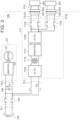
- FIG. 1 is a diagram illustrating a configuration of a vehicle in which an electric power supply system according to an embodiment of the disclosure is installed.
- a vehicle 100 includes a DC (direct current)-DC converter 121, an auxiliary battery 122, an electrical equipment 107, and an electric power supply system 110.
- DC direct current
- the DC-DC converter 121 is connected to an electric power line pair PL2 that connects a system main relay (SMR) 130 and an inverter 125 (both of which will be described later).
- the DC-DC converter 121 converts the electric power flowing over the electric power line pair PL2 into electric power of a voltage level (12 V) for the auxiliary battery 122.
- the DC-DC converter 121 can also convert the electric power supplied from the auxiliary battery 122 into electric power of a voltage level for the electrical equipment 107, and supply the converted electric power to the electric power line pair PL2.
- the electrical equipment 107 includes a compressor 124, the inverter 125, and a motor 127.
- the compressor 124 is connected to the electric power line pair PL2, and is used for air conditioning in the vehicle 100.
- the inverter 125 is connected to the electric power line pair PL2, and drives the motor 127.
- the motor 127 is connected to the inverter 125, and generates traction force for the vehicle 100.
- the electric power supply system 110 is connected to the electrical equipment 107, and includes an electric power storage device 105, a voltage sensor 106, the SMR 130, capacitors 146 and 148, voltage sensors 147 and 149, and a bidirectional electric power conversion device 170.
- the electric power supply system 110 further includes an inlet 192, an outlet 195, a charging device 180, a charging relay 185 and an electronic control unit (ECU) 190.
- ECU electronice control unit
- the electric power storage device 105 is a secondary battery such as a lithium-ion battery or the like, and stores electric power for the vehicle 100 to travel.
- the voltage sensor 106 detects a voltage VB of the electric power storage device 105.
- the SMR 130 is provided between an electric power line pair PL1 connected to the electric power storage device 105, and the electric power line pair PL2 connected to the electrical equipment 107.
- the SMR 130 switches electrical connection between the electric power line pairs PL1 and PL2 between connection and disconnection.
- the SMR 130 includes relays RL1 to RL3 and a current-limiting resistor R1.
- An "off state” of the SMR 130 is a state in which the relays RL1 to RL3 are open.
- An “on state” of the SMR 130 is a state in which the relays RL1 and RL2 are closed. To "turn on” the SMR 130 is to switch the SMR 130 from the off state to the on state.
- the capacitor 146 is provided between the electric power line pair PL2, and is used for smoothing a voltage VL1 between the electric power line pair PL2.
- the voltage sensor 147 detects the voltage VL1.
- the bidirectional electric power conversion device 170 is connected to the electric power line pair PL2 via an electric power line pair PL3, connected to the inlet 192 (described later) via an electric power line pair PL3A, and connected to the outlet 195 (described later) via an electric power line pair PL3B.
- the bidirectional electric power conversion device 170 is configured to execute bidirectional electric power conversion between the electric power line pair PL2 and an electric power facility 200 outside of the vehicle 100.
- the bidirectional electric power conversion device 170 functions as a charging device that converts the electric power received from the electric power facility 200 via the inlet 192, supplies the converted electric power to the electric power line pair PL3, and charges the electric power storage device 105 via the electric power line pair PL2 and the SMR 130 (external charging of vehicle 100).
- the bidirectional electric power conversion device 170 also functions as an electric power feed device that converts electric power received from the electric power storage device 105 via the electric power line pairs PL1, PL2, and PL3, and supplies the converted electric power to the electric power facility 200 via the inlet 192, or to an electric load 250 via the outlet 195 (external electric power feeding from vehicle 100).
- the inlet 192 is configured to connect to the electric power facility 200 via a connector 205 and an electric power line pair PL0. Upon the connector 205 being inserted into the inlet 192, external charging or external electric power feeding from the vehicle 100 to the electric power facility 200 is enabled.
- the outlet 195 is configured to connect to the electric load 250 via a plug 255 of the electric load 250 that is outside of the vehicle 100. Upon the plug 255 being inserted into the outlet 195, external electric power feeding from the vehicle 100 to the electric load 250 is enabled.
- the charging device 180 is used to increase the amount of electric power charged in the electric power storage device 105. Specifically, when the charging device 180 operates in addition to the bidirectional electric power conversion device 170 during external charging, the charged electric power can be increased as compared to when only the bidirectional electric power conversion device 170 operates (charging time can be shortened).
- Whether the charging device 180 operates may be decided in accordance with the rated output electric power of the electric power facility 200. For example, the operating state of the charging device 180 may be decided such that when the output electric power is great, the charging device 180 operates in addition to the bidirectional electric power conversion device 170, whereas when the output power is small, the charging device 180 does not operate (only the bidirectional electric power conversion device 170 operates).
- the charging device 180 is connected to the electric power line pair PL3A via an electric power line pair PL3C, and is provided electrically in parallel with the bidirectional electric power conversion device 170.
- the charging device 180 is connected to the electric power line pair PL1 via an electric power line pair PL4, the charging relay 185 (described later), and an electric power line pair PL1A.
- the charging device 180 is configured to convert electric power supplied from the electric power facility 200 via the inlet 192 and the electric power line pair PL3C to charge the electric power storage device 105.
- the charging relay 185 is connected to the electric power line pair PL1 via the electric power line pair PL1A, and is provided electrically in parallel with the SMR 130.
- the charging relay 185 is provided between the electric power line pair PL1 and the electric power line pair PL4 that is connected to the charging device 180.
- the charging relay 185 includes relays RL11 to RL13, and a current-limiting resistor R2.
- An “off state” of the charging relay 185 is a state in which the relays RL11 to RL13 are open.
- An “on state” of the charging relay 185 is a state in which the relays RL11 and RL12 are closed. To “turn on” the charging relay 185 is to switch the charging relay 185 from an off state to an on state.
- the capacitor 148 is provided between the electric power line pair PL4, and is used for smoothing a voltage VL2 between the electric power line pair PL4.
- the voltage sensor 149 detects the voltage VL2.
- the electric power line pairs PL1, PL2, and PL3, the SMR 130, the bidirectional electric power conversion device 170, and the charging device 180 make up a high-voltage system of the vehicle 100.
- the ECU 190 includes a central processing unit (CPU) and memory (both omitted from illustration).
- the CPU executes various kinds of computation processing.
- the memory includes read-only memory (ROM) and random-access memory (RAM).
- ROM read-only memory
- RAM random-access memory
- the ROM stores programs that are executed by the CPU.
- the RAM functions as working memory.
- the ECU 190 controls each device of the vehicle 100, such as the electrical equipment 107, the SMR 130, the bidirectional electric power conversion device 170, the charging device 180, the charging relay 185, and so forth. For example, when the connector 205 is inserted into the inlet 192, the ECU 190 activates the above-described high-voltage system (permits activation of the system) prior to external charging. The ECU 190 then turns on the SMR 130 and the charging relay 185, and operates both the bidirectional electric power conversion device 170 and the charging device 180 to execute external charging.
- the ECU 190 executes switching processing of the SMR 130 and the charging relay 185 in accordance with the detected voltage values (e.g., voltages VB, VL1, VL2) of the electric power line pairs.
- the detected voltage values e.g., voltages VB, VL1, VL2
- the ECU 190 executes, for example, a first precharge processing of charging the capacitor 146 prior to turning on the SMR 130.
- the first precharge processing is processing of precharging the capacitor 146, by causing the DC-DC converter 121 to supply precharging electric power to the electric power line pair PL2.
- the ECU 190 is an example of a control device.
- the ECU 190 executes a second precharge processing of charging the capacitor 148 prior to turning on the charging relay 185.
- the second precharge processing is processing of controlling the relay RL13 so that the relay RL13 is in the closed state after controlling the relay RL11 so that the relay RL11 is in the closed state and prior to controlling the relay RL12 so that the relay RL12 is in the closed state.
- the capacitor 148 is precharged by the electric power storage device 105 in a situation in which the current is limited by the current-limiting resistor R2.
- FIG. 2 is a diagram illustrating a detailed configuration of the bidirectional electric power conversion device 170.
- the bidirectional electric power conversion device 170 includes relays 1702 and 1703, an AC (alternating current)-DC conversion circuit 1705, an inverter 1710, a transformer 1715, and an AC-DC conversion circuit 1720.
- the relay 1702 is controlled so that the relay 1702 is in a closed state during external charging or during external electric power feeding from the vehicle 100 to the electric power facility 200.
- the relay 1703 is controlled so that the relay 1703 is in a closed state during external electric power feeding from the vehicle 100 to the electric load 250.
- AC-DC conversion circuit 1705 converts alternating current electric power received by the inlet 192 into direct current electric power.
- the inverter 1710 converts the direct current electric power from the AC-DC conversion circuit 1705 into alternating current electric power.
- the transformer 1715 electrically isolates the inverter 1710 and the AC-DC conversion circuit 1720 from each other, while executing transmission of electric power therebetween.
- the AC-DC conversion circuit 1720 converts alternating current electric power from the transformer 1715 into direct current electric power, and supplies the converted electric power to the electric power line pair PL2 via the electric power line pair PL3.
- the AC-DC conversion circuit 1720 can also convert the direct current electric power supplied from electric power storage device 105 via the electric power line pair PL1, the SMR 130, and the electric power line pair PL3 into alternating current electric power, and supply the converted electric power to the electric power facility 200 or the electric load 250 via the transformer 1715.
- FIG. 3 is a diagram illustrating a detailed configuration of the AC-DC conversion circuit 1720.
- the AC-DC conversion circuit 1720 includes switching devices Q1 to Q4, diodes D1 to D4, driving circuits CR1 to CR4, an electric power supply PS, and bootstrap circuits 1725 and 1730.
- Each of the switching devices Q1 to Q4 is a metal-oxide-semiconductor field-effect transistor (MOSFET) in this example, and is connected to the electric power line pair PL3.
- MOSFET metal-oxide-semiconductor field-effect transistor
- the diodes D1 to D4 are connected to the switching devices Q1 to Q4 by inverse-parallel connection, respectively.
- the driving circuits CR1 to CR4 are configured to drive the gates of the switching devices Q1 to Q4, respectively.
- the driving circuits CR1 to CR4 output hold-off signals to the switching devices Q1 to Q4, respectively, so that the voltage from the transformer 1715 is not supplied to the electric power line pair PL2 via the electric power line pair PL3 prior to external charging is started.
- the hold-off signals are output to the respective gates of the switching devices Q1 to Q4, in order to maintain the switching devices Q1 to Q4 in the off state.
- the electric power supply PS is provided to supply operating electric power to the driving circuits CR3 and CR4.
- the bootstrap circuits 1725 and 1730 include a diode D11 and a capacitor C11, and a diode D12 and a capacitor C12, respectively.
- the bootstrap circuits 1725 and 1730 are configured to supply operating electric power to the driving circuits CR1 and CR2 using the electric power supply PS, respectively. Specifically, electric power from the electric power supply PS is supplied to the capacitors C11 and C12 via the diodes D11 and D12, respectively.
- the electric power stored in the capacitors C11 and C12 is used as operating electric power for the driving circuits CR1 and CR2, respectively.
- the single electric power supply PS can supply operating electric power to the driving circuits CR1 to CR4. Accordingly, the configuration of the bidirectional electric power conversion device 170 can be simplified as compared with a case in which a plurality of electric power supplies supply operating electric power to the driving circuits CR1 to CR4.
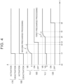
- FIG. 4 is a timing chart for describing an example of processing executed when the bidirectional electric power conversion device 170 and the charging device 180 are activated.
- the second precharge processing (precharging of the capacitor 148) is executed prior to the first precharge processing (precharging of the capacitor 146).
- This example is a comparative example in which the ECU 190, which will be described later, does not execute control.
- the horizontal axis represents time.
- Time t0 is a time at which the connector 205 is inserted into the inlet 192, and both the SMR 130 and the charging relay 185 will be assumed to be off at this time.
- the vertical axis represents activation/deactivation of the bidirectional electric power conversion device 170, activation/deactivation of the charging device 180, the voltage VL2, on/off of the charging relay 185, the voltage VL1, and on/off of the SMR 130, in that order from the top.
- FIGS. 1 to 3 will be referenced as appropriate in the following description.
- an ECU activates the high-voltage system of the vehicle 100 (including the bidirectional electric power conversion device 170 and the charging device 180). This activates the electric power supply PS of the bidirectional electric power conversion device 170. The voltage from the electric power supply PS is then applied to the electric power line pair PL2 via the electric power line pair PL3, via the bootstrap circuit 1725 and the diode D1, and the bootstrap circuit 1730 and the diode D2. As a result, the voltage VL1 changes from 0 to VA (0 ⁇ VA ⁇ VB). Although VA is shown as being constant in this example, for the sake of convenience in illustration, in practice VA can vary within a range of greater than 0 and sufficiently smaller than VB. Accordingly, applying the voltage (VA) to the electric power line pair PL2 prior to the first precharge processing is not intended.
- the ECU starts the second precharge processing by switching the relays RL11 and RL13 from the open state to the closed state. Thereafter, the ECU executes the second precharge processing until time t2 arrives (until voltage VL2 reaches voltage VB). Then, at time t3, the ECU turns on the charging relay 185 by opening the relay RL13 and also closing the relay RL12.
- the ECU starts the first precharge processing by starting operation of the DC-DC converter 121. Thereafter, the ECU executes the first precharge processing until time t5 arrives (until voltage VL1 reaches voltage VB). Then, at time t6, the ECU turns on the SMR 130. Subsequently, external charging is started.
- the second precharge processing is executed prior to the first precharge processing at the activation (time t1) of the bidirectional electric power conversion device 170 prior to external charging.
- voltage is applied to the electric power line pair PL2 from the bootstrap circuits 1725 and 1730 of the bidirectional electric power conversion device 170 prior to execution of the first precharge processing (prior to time t4).
- VA unintended voltage
- the electric power supply system 110 has a configuration that can address the above issues. Specifically, ECU 190 starts the first precharge processing when the bidirectional electric power conversion device 170 is activated. According to such a configuration, precharging of the capacitor 146 and application of voltage from the bidirectional electric power conversion device 170 to the electric power line pair PL2 are performed simultaneously when the bidirectional electric power conversion device 170 is activated. The voltage applied from the bidirectional electric power conversion device 170 to the electric power line pair PL2 is sufficiently smaller than the voltage of the electric power for precharging of the capacitor 146 from the DC-DC converter 121.
- the voltage from the bidirectional electric power conversion device 170 to the electric power line pair PL2 is substantially masked by the voltage of the electric power for precharging of the capacitor 146.
- the effects on the electrical equipment 107 due to the application of voltage from the bidirectional electric power conversion device 170 to the electric power line pair PL2 can be suppressed.
- the ECU 190 activates both the bidirectional electric power conversion device 170 and the charging device 180 prior to external charging.
- the ECU 190 starts the first precharge processing prior to the second precharge processing. If the second precharge processing is started prior to the first precharge processing, the voltage may be applied from the bootstrap circuits 1725 and 1730 to the electric power line pair PL2 prior to the first precharge processing as in the comparative example, and there is a possibility that an unintended voltage will be applied to the electrical equipment, such as the inverter 125 and so forth.
- the first precharge processing is executed prior to the second precharge processing and is executed when the bidirectional electric power conversion device 170 is activated. As a result, unintended voltage application to the electrical equipment can be averted.
- FIG. 5 is a timing chart for describing processing executed by the ECU 190 when the bidirectional electric power conversion device 170 and the charging device 180 are activated.
- the horizontal axis and the vertical axis are the same as those in the comparative example ( FIG. 4 ).
- Times t10 and t11 are the same as times t0 and t1 in the comparative example, respectively.
- FIG. 5 is an example of an embodiment according to the present disclosure.
- the ECU 190 activates both the bidirectional electric power conversion device 170 and the charging device 180, and starts the first precharge processing. Accordingly, precharging of the capacitor 146 and application of the voltage from the bidirectional electric power conversion device 170 to the electric power line pair PL2 are performed simultaneously when the bidirectional electric power conversion device 170 is activated. As a result, the voltage from the bidirectional electric power conversion device 170 to the electric power line pair PL2 is substantially masked by the voltage of the precharging electric power for the capacitor 146. Accordingly, unintended voltage can be averted from being generated on the electric power line pair PL2.
- the ECU 190 executes the first precharge processing until time t12 arrives (until voltage VL1 reaches voltage VB). At time t13, the ECU 190 turns on the SMR 130.
- the ECU 190 starts the second precharge processing. Thereafter, the ECU 190 executes the second precharge processing until time t15 arrives (until voltage VL2 reaches voltage VB). Then, at time t16, the ECU 190 turns on the charging relay 185. Subsequently, external charging is started.
- FIG. 6 is a flowchart showing an example of processing executed by the ECU 190 in association with external charging. The processing of this flowchart is started when the connector 205 is inserted into the inlet 192. In the following description, FIG. 5 will be referenced as appropriate.
- the ECU 190 activates the bidirectional electric power conversion device 170 and the charging device 180 (step S105), and starts the first precharge processing (step S110).
- the ECU 190 determines whether precharging of the capacitor 146 is complete (step S115). Specifically, ECU 190 executes this determination processing in accordance with whether the voltage VL1 has reached the voltage VB. When precharging is not yet complete (NO in step S115), the ECU 190 executes this determination processing until this precharging is complete. On the other hand, when precharging is complete (YES in step S115), the ECU 190 turns on the SMR 130 at time t13 (step S120).
- step S125 the ECU 190 starts the second precharge processing at time t14 (step S125).
- the ECU 190 determines whether precharging of the capacitor 148 is complete (step S130). Specifically, the ECU 190 executes this determination processing in accordance with whether the voltage VL2 has reached the voltage VB. When precharging is not yet complete (NO in step S130), the ECU 190 executes this determination processing until this precharging is complete. On the other hand, when precharging is complete (YES in step S130), the ECU 190 turns on the charging relay 185 at time t16 (step S135). Subsequently, the ECU 190 starts external charging (step S140).
- a situation can be averted in which an unintended voltage is applied to the electrical equipment, such as the inverter 125 and so forth, from the electric power supply PS via the bootstrap circuits 1725 and 1730, when the bidirectional electric power conversion device 170 is activated prior to the SMR 130 being turned on.
- the first precharge processing may be processing of controlling the relay RL3 of the SMR 130 so that the relay RL3 is in the closed state, after controlling the relay RL1 so that the relay RL1 to the closed state and prior to controlling the relay RL2 so that the relay RL2 is in the closed state. That is to say, the first precharge processing may be executed without using the DC-DC converter 121, in the same way as in the second precharge processing.
Landscapes
- Engineering & Computer Science (AREA)
- Power Engineering (AREA)
- Transportation (AREA)
- Mechanical Engineering (AREA)
- Life Sciences & Earth Sciences (AREA)
- Sustainable Development (AREA)
- Sustainable Energy (AREA)
- Emergency Management (AREA)
- Business, Economics & Management (AREA)
- Electric Propulsion And Braking For Vehicles (AREA)
- Charge And Discharge Circuits For Batteries Or The Like (AREA)
- Dc-Dc Converters (AREA)
- Manufacturing & Machinery (AREA)
- Chemical & Material Sciences (AREA)
- Chemical Kinetics & Catalysis (AREA)
- Electrochemistry (AREA)
- General Chemical & Material Sciences (AREA)
Abstract
An electric power supply system (110) includes an electric power storage device (105), a first relay (130) provided between a first electric power line pair (PL1) connected to the electric power storage device (105) and a second electric power line pair (PL2) connected to an electrical equipment (107), a bidirectional electric power conversion device that is configured to bidirectionally convert electric power between the second electric power line pair and an electric power facility (200) outside of a vehicle, a first capacitor (146) provided between the second electric power line pair, and a control device (190) configured to execute a first precharge processing of charging the first capacitor prior to turning on the first relay, wherein the bidirectional electric power conversion device (170) includes a switching device, and wherein the control device is configured to start the first precharge processing when the bidirectional electric power conversion device (170) is activated.
Description
- The present disclosure relates to an electric power supply system, and more particularly to an electric power supply system connected to an electrical equipment.
-
Japanese Unexamined Patent Application Publication No. 2009-131077 JP 2009-131077 A - There are cases in which a charging device, such as that described above, is configured with a bidirectional electric power conversion device that can also perform electric power feeding to an electrical facility outside of the vehicle. Unlike electric power conversion devices that have charging-only functions (e.g., rectifier circuits), bidirectional electric power conversion devices include switching devices connected to electric power line pairs through which charging or feeding electric power flows, and driving circuits thereof. During activation of the bidirectional electric power conversion device, the electric power supply of the driving circuit supplies operating electric power to the driving circuit, so that the switching devices are maintained in an off state. However, voltage may be applied to the electric power line pair from this electric power supply.
- Various kinds of problems may occur when unintended voltage is applied to the electric power line pair to which an electrical equipment such as an inverter is connected, when the bidirectional electric power conversion device is activated prior to the SMR being turned on.
- The present disclosure can solve the above problems, and in an electric power supply system connected to an electrical equipment, a situation can be averted in which unintended voltage is applied to the electrical equipment when a bidirectional electric power conversion device is activated.
- An electric power supply system according to one aspect of the present disclosure is configured to be connected to an electrical equipment. The electric power supply system includes an electric power storage device, a first relay, a bidirectional electric power conversion device, a first capacitor, and a control device. The first relay is provided between a first electric power line pair and a second electric power line pair, the first electric power line pair being connected to the electric power storage device and the second electric power line pair being connected to the electrical equipment. The bidirectional electric power conversion device is connected to the second electric power line pair via a third electric power line pair and is configured to bidirectionally convert electric power between the second electric power line pair and an electric power facility outside of a vehicle. The first capacitor is provided between the second electric power line pair. The control device is configured to execute a first precharge processing of charging the first capacitor prior to turning on the first relay. The bidirectional electric power conversion device includes a switching device connected to the third electric power line pair. The control device is configured to start the first precharge processing when the bidirectional electric power conversion device is activated.
- When the bidirectional electric power conversion device is activated, there is a possibility that voltage will be applied to the second electric power line pair from the electric power supply for the driving circuit for the switching device of the bidirectional electric power conversion device. As a result, there is a possibility that an unintended voltage will be applied to the electrical equipment. According to the above configuration, precharging of the first capacitor and application of voltage from the bidirectional electric power conversion device to the second electric power line pair are executed simultaneously when the bidirectional electric power conversion device is activated. The voltage applied from the bidirectional electric power conversion device to the second electric power line pair is sufficiently smaller than the voltage of the electric power for precharging the first capacitor. Accordingly, when the first precharge processing is started as described above, the voltage from the bidirectional electric power conversion device to the second electric power line pair is substantially masked by the voltage of the electric power for precharging the first capacitor. Thus, the effects on the electrical equipment due to the application of voltage from the bidirectional electric power conversion device to the second electric power line pair can be suppressed. As a result, a situation can be averted in which an unintended voltage is applied to the electrical equipment when the bidirectional electric power conversion device is activated prior to the SMR being turned on.
- In the electric power supply system according to the aspect described above, the bidirectional electric power conversion device may include a driving circuit, and a bootstrap circuit. The driving circuit may drive the switching device. The bootstrap circuit may supply operating electric power to the driving circuit.
- According to the above configuration, the configuration of the bidirectional electric power conversion device can be simplified.
- The electric power supply system according to the above aspect may further include a charging device, a second relay, and a second capacitor. The charging device may be connected to the first electric power line pair and be configured to convert electric power supplied from the electric power facility to charge the electric power storage device. The second relay may be provided between the first electric power line pair and a fourth electric power line pair connected to the charging device. The second capacitor may be provided between the fourth electric power line pair. The control device may be configured to further execute a second precharge processing of charging the second capacitor prior to turning on the second relay. The control device may be configured to start the first precharge processing prior to the second precharge processing when both the bidirectional electric power conversion device and the charging device are activated.
- If the second precharge processing is started prior to the first precharge processing when both the bidirectional electric power conversion device and the charging device are activated, there is a possibility that voltage will be applied from the bidirectional electric power conversion device to the second electric power line pair prior to precharging of the first capacitor. As a result, there is a possibility that an unintended voltage will be applied to the electrical equipment. Such a situation can be averted by employing the above configuration.
- According to the present disclosure, in the electric power supply system connected to the electrical equipment, a situation can be averted in which unintended voltage is applied to the electrical equipment when the bidirectional electric power conversion device is activated.
- Features, advantages, and technical and industrial significance of exemplary embodiments of the invention will be described below with reference to the accompanying drawings, in which like signs denote like elements, and wherein:
-
FIG. 1 is a diagram illustrating a configuration of a vehicle in which an electric power supply system according to an embodiment is installed; -
FIG. 2 is a diagram illustrating a detailed configuration of a bidirectional electric power conversion device; -
FIG. 3 is a diagram illustrating a detailed configuration of an alternating current (AC)-direct current (DC) conversion circuit; -
FIG. 4 is a timing chart for describing an example of processing executed when the bidirectional electric power conversion device and a charging device are activated; -
FIG. 5 is a timing chart for describing processing executed by an electronic control unit (ECU) when the bidirectional electric power conversion device and the charging device are activated; and -
FIG. 6 is a flowchart showing an example of processing executed by the ECU in association with external charging. - An embodiment of the present disclosure will be described in detail below with reference to the drawings. Like or corresponding portions are denoted by like signs throughout the drawings, and description thereof will not be repeated.
-
FIG. 1 is a diagram illustrating a configuration of a vehicle in which an electric power supply system according to an embodiment of the disclosure is installed. Referring toFIG. 1 , avehicle 100 includes a DC (direct current)-DC converter 121, anauxiliary battery 122, anelectrical equipment 107, and an electricpower supply system 110. - The DC-
DC converter 121 is connected to an electric power line pair PL2 that connects a system main relay (SMR) 130 and an inverter 125 (both of which will be described later). The DC-DC converter 121 converts the electric power flowing over the electric power line pair PL2 into electric power of a voltage level (12 V) for theauxiliary battery 122. The DC-DC converter 121 can also convert the electric power supplied from theauxiliary battery 122 into electric power of a voltage level for theelectrical equipment 107, and supply the converted electric power to the electric power line pair PL2. - The
electrical equipment 107 includes acompressor 124, theinverter 125, and amotor 127. Thecompressor 124 is connected to the electric power line pair PL2, and is used for air conditioning in thevehicle 100. Theinverter 125 is connected to the electric power line pair PL2, and drives themotor 127. Themotor 127 is connected to theinverter 125, and generates traction force for thevehicle 100. - The electric
power supply system 110 is connected to theelectrical equipment 107, and includes an electricpower storage device 105, avoltage sensor 106, theSMR 130,capacitors voltage sensors power conversion device 170. The electricpower supply system 110 further includes aninlet 192, anoutlet 195, acharging device 180, a chargingrelay 185 and an electronic control unit (ECU) 190. - The electric
power storage device 105 is a secondary battery such as a lithium-ion battery or the like, and stores electric power for thevehicle 100 to travel. Thevoltage sensor 106 detects a voltage VB of the electricpower storage device 105. - The
SMR 130 is provided between an electric power line pair PL1 connected to the electricpower storage device 105, and the electric power line pair PL2 connected to theelectrical equipment 107. TheSMR 130 switches electrical connection between the electric power line pairs PL1 and PL2 between connection and disconnection. TheSMR 130 includes relays RL1 to RL3 and a current-limiting resistor R1. An "off state" of theSMR 130 is a state in which the relays RL1 to RL3 are open. An "on state" of theSMR 130 is a state in which the relays RL1 and RL2 are closed. To "turn on" theSMR 130 is to switch theSMR 130 from the off state to the on state. - The
capacitor 146 is provided between the electric power line pair PL2, and is used for smoothing a voltage VL1 between the electric power line pair PL2. Thevoltage sensor 147 detects the voltage VL1. - The bidirectional electric
power conversion device 170 is connected to the electric power line pair PL2 via an electric power line pair PL3, connected to the inlet 192 (described later) via an electric power line pair PL3A, and connected to the outlet 195 (described later) via an electric power line pair PL3B. - The bidirectional electric
power conversion device 170 is configured to execute bidirectional electric power conversion between the electric power line pair PL2 and anelectric power facility 200 outside of thevehicle 100. The bidirectional electricpower conversion device 170 functions as a charging device that converts the electric power received from theelectric power facility 200 via theinlet 192, supplies the converted electric power to the electric power line pair PL3, and charges the electricpower storage device 105 via the electric power line pair PL2 and the SMR 130 (external charging of vehicle 100). On the other hand, the bidirectional electricpower conversion device 170 also functions as an electric power feed device that converts electric power received from the electricpower storage device 105 via the electric power line pairs PL1, PL2, and PL3, and supplies the converted electric power to theelectric power facility 200 via theinlet 192, or to anelectric load 250 via the outlet 195 (external electric power feeding from vehicle 100). - The
inlet 192 is configured to connect to theelectric power facility 200 via aconnector 205 and an electric power line pair PL0. Upon theconnector 205 being inserted into theinlet 192, external charging or external electric power feeding from thevehicle 100 to theelectric power facility 200 is enabled. - The
outlet 195 is configured to connect to theelectric load 250 via aplug 255 of theelectric load 250 that is outside of thevehicle 100. Upon theplug 255 being inserted into theoutlet 195, external electric power feeding from thevehicle 100 to theelectric load 250 is enabled. - The charging
device 180 is used to increase the amount of electric power charged in the electricpower storage device 105. Specifically, when thecharging device 180 operates in addition to the bidirectional electricpower conversion device 170 during external charging, the charged electric power can be increased as compared to when only the bidirectional electricpower conversion device 170 operates (charging time can be shortened). - Whether the
charging device 180 operates may be decided in accordance with the rated output electric power of theelectric power facility 200. For example, the operating state of thecharging device 180 may be decided such that when the output electric power is great, the chargingdevice 180 operates in addition to the bidirectional electricpower conversion device 170, whereas when the output power is small, the chargingdevice 180 does not operate (only the bidirectional electricpower conversion device 170 operates). - The charging
device 180 is connected to the electric power line pair PL3A via an electric power line pair PL3C, and is provided electrically in parallel with the bidirectional electricpower conversion device 170. The chargingdevice 180 is connected to the electric power line pair PL1 via an electric power line pair PL4, the charging relay 185 (described later), and an electric power line pair PL1A. The chargingdevice 180 is configured to convert electric power supplied from theelectric power facility 200 via theinlet 192 and the electric power line pair PL3C to charge the electricpower storage device 105. - The charging
relay 185 is connected to the electric power line pair PL1 via the electric power line pair PL1A, and is provided electrically in parallel with theSMR 130. The chargingrelay 185 is provided between the electric power line pair PL1 and the electric power line pair PL4 that is connected to thecharging device 180. The chargingrelay 185 includes relays RL11 to RL13, and a current-limiting resistor R2. An "off state" of the chargingrelay 185 is a state in which the relays RL11 to RL13 are open. An "on state" of the chargingrelay 185 is a state in which the relays RL11 and RL12 are closed. To "turn on" the chargingrelay 185 is to switch the chargingrelay 185 from an off state to an on state. - The
capacitor 148 is provided between the electric power line pair PL4, and is used for smoothing a voltage VL2 between the electric power line pair PL4. Thevoltage sensor 149 detects the voltage VL2. - The electric power line pairs PL1, PL2, and PL3, the
SMR 130, the bidirectional electricpower conversion device 170, and thecharging device 180 make up a high-voltage system of thevehicle 100. - The
ECU 190 includes a central processing unit (CPU) and memory (both omitted from illustration). The CPU executes various kinds of computation processing. The memory includes read-only memory (ROM) and random-access memory (RAM). The ROM stores programs that are executed by the CPU. The RAM functions as working memory. - The
ECU 190 controls each device of thevehicle 100, such as theelectrical equipment 107, theSMR 130, the bidirectional electricpower conversion device 170, the chargingdevice 180, the chargingrelay 185, and so forth. For example, when theconnector 205 is inserted into theinlet 192, theECU 190 activates the above-described high-voltage system (permits activation of the system) prior to external charging. TheECU 190 then turns on theSMR 130 and the chargingrelay 185, and operates both the bidirectional electricpower conversion device 170 and thecharging device 180 to execute external charging. - The
ECU 190 executes switching processing of theSMR 130 and the chargingrelay 185 in accordance with the detected voltage values (e.g., voltages VB, VL1, VL2) of the electric power line pairs. - The
ECU 190 executes, for example, a first precharge processing of charging thecapacitor 146 prior to turning on theSMR 130. In this example, the first precharge processing is processing of precharging thecapacitor 146, by causing the DC-DC converter 121 to supply precharging electric power to the electric power line pair PL2. TheECU 190 is an example of a control device. - The
ECU 190 executes a second precharge processing of charging thecapacitor 148 prior to turning on the chargingrelay 185. The second precharge processing is processing of controlling the relay RL13 so that the relay RL13 is in the closed state after controlling the relay RL11 so that the relay RL11 is in the closed state and prior to controlling the relay RL12 so that the relay RL12 is in the closed state. Thus, thecapacitor 148 is precharged by the electricpower storage device 105 in a situation in which the current is limited by the current-limiting resistor R2. -
FIG. 2 is a diagram illustrating a detailed configuration of the bidirectional electricpower conversion device 170. Referring toFIG. 2 , the bidirectional electricpower conversion device 170 includesrelays DC conversion circuit 1705, aninverter 1710, atransformer 1715, and an AC-DC conversion circuit 1720. - The
relay 1702 is controlled so that therelay 1702 is in a closed state during external charging or during external electric power feeding from thevehicle 100 to theelectric power facility 200. Therelay 1703 is controlled so that therelay 1703 is in a closed state during external electric power feeding from thevehicle 100 to theelectric load 250. AC-DC conversion circuit 1705 converts alternating current electric power received by theinlet 192 into direct current electric power. Theinverter 1710 converts the direct current electric power from the AC-DC conversion circuit 1705 into alternating current electric power. Thetransformer 1715 electrically isolates theinverter 1710 and the AC-DC conversion circuit 1720 from each other, while executing transmission of electric power therebetween. - The AC-
DC conversion circuit 1720 converts alternating current electric power from thetransformer 1715 into direct current electric power, and supplies the converted electric power to the electric power line pair PL2 via the electric power line pair PL3. The AC-DC conversion circuit 1720 can also convert the direct current electric power supplied from electricpower storage device 105 via the electric power line pair PL1, theSMR 130, and the electric power line pair PL3 into alternating current electric power, and supply the converted electric power to theelectric power facility 200 or theelectric load 250 via thetransformer 1715. -
FIG. 3 is a diagram illustrating a detailed configuration of the AC-DC conversion circuit 1720. Referring toFIG. 3 , the AC-DC conversion circuit 1720 includes switching devices Q1 to Q4, diodes D1 to D4, driving circuits CR1 to CR4, an electric power supply PS, andbootstrap circuits - Each of the switching devices Q1 to Q4 is a metal-oxide-semiconductor field-effect transistor (MOSFET) in this example, and is connected to the electric power line pair PL3. The diodes D1 to D4 are connected to the switching devices Q1 to Q4 by inverse-parallel connection, respectively.
- The driving circuits CR1 to CR4 are configured to drive the gates of the switching devices Q1 to Q4, respectively. The driving circuits CR1 to CR4 output hold-off signals to the switching devices Q1 to Q4, respectively, so that the voltage from the
transformer 1715 is not supplied to the electric power line pair PL2 via the electric power line pair PL3 prior to external charging is started. The hold-off signals are output to the respective gates of the switching devices Q1 to Q4, in order to maintain the switching devices Q1 to Q4 in the off state. The electric power supply PS is provided to supply operating electric power to the driving circuits CR3 and CR4. - The
bootstrap circuits bootstrap circuits - Thus, in a case in which the bidirectional electric
power conversion device 170 includes thebootstrap circuits power conversion device 170 can be simplified as compared with a case in which a plurality of electric power supplies supply operating electric power to the driving circuits CR1 to CR4. -
FIG. 4 is a timing chart for describing an example of processing executed when the bidirectional electricpower conversion device 170 and thecharging device 180 are activated. In this example, the second precharge processing (precharging of the capacitor 148) is executed prior to the first precharge processing (precharging of the capacitor 146). This example is a comparative example in which theECU 190, which will be described later, does not execute control. - Referring to
FIG. 4 , the horizontal axis represents time. Time t0 is a time at which theconnector 205 is inserted into theinlet 192, and both theSMR 130 and the chargingrelay 185 will be assumed to be off at this time. The vertical axis represents activation/deactivation of the bidirectional electricpower conversion device 170, activation/deactivation of thecharging device 180, the voltage VL2, on/off of the chargingrelay 185, the voltage VL1, and on/off of theSMR 130, in that order from the top.FIGS. 1 to 3 will be referenced as appropriate in the following description. - At time t1, an ECU according to the comparative example activates the high-voltage system of the vehicle 100 (including the bidirectional electric
power conversion device 170 and the charging device 180). This activates the electric power supply PS of the bidirectional electricpower conversion device 170. The voltage from the electric power supply PS is then applied to the electric power line pair PL2 via the electric power line pair PL3, via thebootstrap circuit 1725 and the diode D1, and thebootstrap circuit 1730 and the diode D2. As a result, the voltage VL1 changes from 0 to VA (0 < VA << VB). Although VA is shown as being constant in this example, for the sake of convenience in illustration, in practice VA can vary within a range of greater than 0 and sufficiently smaller than VB. Accordingly, applying the voltage (VA) to the electric power line pair PL2 prior to the first precharge processing is not intended. - At time t1, the ECU starts the second precharge processing by switching the relays RL11 and RL13 from the open state to the closed state. Thereafter, the ECU executes the second precharge processing until time t2 arrives (until voltage VL2 reaches voltage VB). Then, at time t3, the ECU turns on the charging
relay 185 by opening the relay RL13 and also closing the relay RL12. - At time t4, the ECU starts the first precharge processing by starting operation of the DC-
DC converter 121. Thereafter, the ECU executes the first precharge processing until time t5 arrives (until voltage VL1 reaches voltage VB). Then, at time t6, the ECU turns on theSMR 130. Subsequently, external charging is started. - In the above comparative example, the second precharge processing is executed prior to the first precharge processing at the activation (time t1) of the bidirectional electric
power conversion device 170 prior to external charging. Thus, voltage is applied to the electric power line pair PL2 from thebootstrap circuits power conversion device 170 prior to execution of the first precharge processing (prior to time t4). As a result, an unintended voltage (VA) is applied to the electric power line pair PL2. - The electric
power supply system 110 according to the present embodiment has a configuration that can address the above issues. Specifically,ECU 190 starts the first precharge processing when the bidirectional electricpower conversion device 170 is activated. According to such a configuration, precharging of thecapacitor 146 and application of voltage from the bidirectional electricpower conversion device 170 to the electric power line pair PL2 are performed simultaneously when the bidirectional electricpower conversion device 170 is activated. The voltage applied from the bidirectional electricpower conversion device 170 to the electric power line pair PL2 is sufficiently smaller than the voltage of the electric power for precharging of thecapacitor 146 from the DC-DC converter 121. Accordingly, when the first precharge processing is started as described above, the voltage from the bidirectional electricpower conversion device 170 to the electric power line pair PL2 is substantially masked by the voltage of the electric power for precharging of thecapacitor 146. As a result, the effects on theelectrical equipment 107 due to the application of voltage from the bidirectional electricpower conversion device 170 to the electric power line pair PL2 can be suppressed. - In the present embodiment, the
ECU 190 activates both the bidirectional electricpower conversion device 170 and thecharging device 180 prior to external charging. When activating both the bidirectional electricpower conversion device 170 and thecharging device 180, theECU 190 starts the first precharge processing prior to the second precharge processing. If the second precharge processing is started prior to the first precharge processing, the voltage may be applied from thebootstrap circuits inverter 125 and so forth. Conversely, in the present embodiment, the first precharge processing is executed prior to the second precharge processing and is executed when the bidirectional electricpower conversion device 170 is activated. As a result, unintended voltage application to the electrical equipment can be averted. -
FIG. 5 is a timing chart for describing processing executed by theECU 190 when the bidirectional electricpower conversion device 170 and thecharging device 180 are activated. Referring toFIG. 5 , the horizontal axis and the vertical axis are the same as those in the comparative example (FIG. 4 ). Times t10 and t11 are the same as times t0 and t1 in the comparative example, respectively.FIG. 5 is an example of an embodiment according to the present disclosure. - At time t11, the
ECU 190 activates both the bidirectional electricpower conversion device 170 and thecharging device 180, and starts the first precharge processing. Accordingly, precharging of thecapacitor 146 and application of the voltage from the bidirectional electricpower conversion device 170 to the electric power line pair PL2 are performed simultaneously when the bidirectional electricpower conversion device 170 is activated. As a result, the voltage from the bidirectional electricpower conversion device 170 to the electric power line pair PL2 is substantially masked by the voltage of the precharging electric power for thecapacitor 146. Accordingly, unintended voltage can be averted from being generated on the electric power line pair PL2. - The
ECU 190 executes the first precharge processing until time t12 arrives (until voltage VL1 reaches voltage VB). At time t13, theECU 190 turns on theSMR 130. - At time t14, the
ECU 190 starts the second precharge processing. Thereafter, theECU 190 executes the second precharge processing until time t15 arrives (until voltage VL2 reaches voltage VB). Then, at time t16, theECU 190 turns on the chargingrelay 185. Subsequently, external charging is started. -
FIG. 6 is a flowchart showing an example of processing executed by theECU 190 in association with external charging. The processing of this flowchart is started when theconnector 205 is inserted into theinlet 192. In the following description,FIG. 5 will be referenced as appropriate. - Referring to
FIG. 6 , at time t11, theECU 190 activates the bidirectional electricpower conversion device 170 and the charging device 180 (step S105), and starts the first precharge processing (step S110). - Next, the
ECU 190 determines whether precharging of thecapacitor 146 is complete (step S115). Specifically,ECU 190 executes this determination processing in accordance with whether the voltage VL1 has reached the voltage VB. When precharging is not yet complete (NO in step S115), theECU 190 executes this determination processing until this precharging is complete. On the other hand, when precharging is complete (YES in step S115), theECU 190 turns on theSMR 130 at time t13 (step S120). - Next, the
ECU 190 starts the second precharge processing at time t14 (step S125). - Next, the
ECU 190 determines whether precharging of thecapacitor 148 is complete (step S130). Specifically, theECU 190 executes this determination processing in accordance with whether the voltage VL2 has reached the voltage VB. When precharging is not yet complete (NO in step S130), theECU 190 executes this determination processing until this precharging is complete. On the other hand, when precharging is complete (YES in step S130), theECU 190 turns on the chargingrelay 185 at time t16 (step S135). Subsequently, theECU 190 starts external charging (step S140). - As described above, according to the present embodiment, a situation can be averted in which an unintended voltage is applied to the electrical equipment, such as the
inverter 125 and so forth, from the electric power supply PS via thebootstrap circuits power conversion device 170 is activated prior to theSMR 130 being turned on. - The first precharge processing may be processing of controlling the relay RL3 of the
SMR 130 so that the relay RL3 is in the closed state, after controlling the relay RL1 so that the relay RL1 to the closed state and prior to controlling the relay RL2 so that the relay RL2 is in the closed state. That is to say, the first precharge processing may be executed without using the DC-DC converter 121, in the same way as in the second precharge processing. - The embodiments disclosed herein should be understood as exemplary in all respects and not limiting. The scope of the invention is defined by the claims rather than by the above description, and is intended to include all modifications that fall within the meaning and scope equivalent to those of the claims.
Claims (3)
- An electric power supply system (110) configured to be connected to an electrical equipment (107), the electric power supply system (110) comprising:an electric power storage device (105);a first relay (130) provided between a first electric power line pair (PL1) and a second electric power line pair (PL2), the first electric power line pair (PL1) being connected to the electric power storage device (105) and the second electric power line pair (PL2) being connected to the electrical equipment (107);a bidirectional electric power conversion device (170) that is connected to the second electric power line pair (PL2) via a third electric power line pair (PL3), the bidirectional electric power conversion device (170) being configured to bidirectionally convert electric power between the second electric power line pair (PL2) and an electric power facility (200) outside of a vehicle (100);a first capacitor (146) provided between the second electric power line pair (PL2); anda control device (190) configured to execute a first precharge processing of charging the first capacitor (146) prior to turning on the first relay (130), whereinthe bidirectional electric power conversion device (170) includes a switching device (Q1, Q2, Q3, Q4) connected to the third electric power line pair (PL3), and whereinthe control device (190) is configured to start the first precharge processing when the bidirectional electric power conversion device (170) is activated.
- The electric power supply system (110) according to claim 1, wherein the bidirectional electric power conversion device (170) includesa driving circuit (CR1, CR2, CR3, CR4) for driving the switching device (Q1, Q2, Q3, Q4), anda bootstrap circuit (1725, 1730) that supplies operating electric power to the driving circuit (CR1, CR2, CR3, CR4).
- The electric power supply system (110) according to claim 1 or 2, further comprising:a charging device (180) that is connected to the first electric power line pair (PL1), the charging device (180) being configured to convert electric power supplied from the electric power facility (200) to charge the electric power storage device (105);a second relay (185) provided between the first electric power line pair (PL1) and a fourth electric power line pair (PL4) connected to the charging device (180); anda second capacitor (148) provided between the fourth electric power line pair (PL4), wherein the control device (190)is configured to further execute a second precharge processing of charging the second capacitor (148) prior to turning on the second relay (185), andis configured to start the first precharge processing prior to the second precharge processing when both the bidirectional electric power conversion device (170) and the charging device (180) are activated.
Applications Claiming Priority (1)
| Application Number | Priority Date | Filing Date | Title |
|---|---|---|---|
| JP2022068298A JP7643386B2 (en) | 2022-04-18 | 2022-04-18 | Power System |
Publications (1)
| Publication Number | Publication Date |
|---|---|
| EP4265473A1 true EP4265473A1 (en) | 2023-10-25 |
Family
ID=85199050
Family Applications (1)
| Application Number | Title | Priority Date | Filing Date |
|---|---|---|---|
| EP23155370.2A Pending EP4265473A1 (en) | 2022-04-18 | 2023-02-07 | Electric power supply system |
Country Status (4)
| Country | Link |
|---|---|
| US (1) | US12322995B2 (en) |
| EP (1) | EP4265473A1 (en) |
| JP (1) | JP7643386B2 (en) |
| CN (1) | CN116915075A (en) |
Families Citing this family (3)
| Publication number | Priority date | Publication date | Assignee | Title |
|---|---|---|---|---|
| JP7661933B2 (en) * | 2022-06-03 | 2025-04-15 | トヨタ自動車株式会社 | Electric vehicles |
| JP2025072050A (en) * | 2023-10-24 | 2025-05-09 | 本田技研工業株式会社 | Power System |
| JP2025097125A (en) * | 2023-12-18 | 2025-06-30 | トヨタ自動車株式会社 | charging device |
Citations (4)
| Publication number | Priority date | Publication date | Assignee | Title |
|---|---|---|---|---|
| US20090108674A1 (en) * | 2006-04-24 | 2009-04-30 | Toyota Jidosha Kabushiki Kaisha | Power Supply Control Device and Method of Detecting Abnormality of Relay |
| JP2009131077A (en) | 2007-11-26 | 2009-06-11 | Toyota Motor Corp | Vehicle power supply |
| US20150311797A1 (en) * | 2012-12-03 | 2015-10-29 | Panasonic Intellectual Property Management Co., Lt | Dc-dc converter |
| US9290105B2 (en) * | 2011-12-31 | 2016-03-22 | Shenzhen Byd Auto R&D Company Limited | Electric vehicle and active discharging system for electric vehicle |
Family Cites Families (5)
| Publication number | Priority date | Publication date | Assignee | Title |
|---|---|---|---|---|
| JP5348334B2 (en) * | 2011-04-13 | 2013-11-20 | トヨタ自動車株式会社 | Power supply device for electric vehicle and control method thereof |
| CN103492214B (en) * | 2011-04-21 | 2015-09-30 | 丰田自动车株式会社 | The supply unit of elec. vehicle and control method thereof |
| JP5884700B2 (en) | 2012-10-02 | 2016-03-15 | トヨタ自動車株式会社 | Vehicle control apparatus and vehicle |
| US9484818B2 (en) | 2013-01-31 | 2016-11-01 | Panasonic Intellectual Property Management Co., Ltd. | DC-DC converter |
| JP6919546B2 (en) | 2017-12-13 | 2021-08-18 | トヨタ自動車株式会社 | Vehicle power supply system |
-
2022
- 2022-04-18 JP JP2022068298A patent/JP7643386B2/en active Active
-
2023
- 2023-01-30 CN CN202310116801.3A patent/CN116915075A/en active Pending
- 2023-02-01 US US18/104,626 patent/US12322995B2/en active Active
- 2023-02-07 EP EP23155370.2A patent/EP4265473A1/en active Pending
Patent Citations (4)
| Publication number | Priority date | Publication date | Assignee | Title |
|---|---|---|---|---|
| US20090108674A1 (en) * | 2006-04-24 | 2009-04-30 | Toyota Jidosha Kabushiki Kaisha | Power Supply Control Device and Method of Detecting Abnormality of Relay |
| JP2009131077A (en) | 2007-11-26 | 2009-06-11 | Toyota Motor Corp | Vehicle power supply |
| US9290105B2 (en) * | 2011-12-31 | 2016-03-22 | Shenzhen Byd Auto R&D Company Limited | Electric vehicle and active discharging system for electric vehicle |
| US20150311797A1 (en) * | 2012-12-03 | 2015-10-29 | Panasonic Intellectual Property Management Co., Lt | Dc-dc converter |
Also Published As
| Publication number | Publication date |
|---|---|
| CN116915075A (en) | 2023-10-20 |
| JP2023158447A (en) | 2023-10-30 |
| US12322995B2 (en) | 2025-06-03 |
| US20230336087A1 (en) | 2023-10-19 |
| JP7643386B2 (en) | 2025-03-11 |
Similar Documents
| Publication | Publication Date | Title |
|---|---|---|
| EP4265473A1 (en) | Electric power supply system | |
| US10897190B2 (en) | Power supply device, power control apparatus, and relay determination method for power supply device | |
| CN109428473B (en) | vehicle power system | |
| US20190214920A1 (en) | Switching power supply device | |
| EP2497677B1 (en) | Electric vehicle | |
| JPH10164709A (en) | Power supply and power supply for electric vehicle | |
| CN101712284A (en) | Automotive electrical system for coupling power converters with a transformer | |
| US10826318B2 (en) | Voltage increasing and decreasing device for power storage apparatus and power storage apparatus | |
| CN104979865A (en) | Active isolated circuit for precharging and discharging a high voltage bus | |
| JP2019004547A (en) | Charging control device | |
| CN115666997B (en) | Power supply system and control method of power supply system | |
| US20170361716A1 (en) | Power conversion system | |
| CN104205593B (en) | Supply unit | |
| EP2621072B1 (en) | Motor control device | |
| US20150295445A1 (en) | Electric power conversion apparatus and method of controlling the same | |
| WO2017179158A1 (en) | Battery module | |
| JP5683552B2 (en) | Vehicle charging device | |
| JP6962379B2 (en) | Power storage device | |
| JP6700060B2 (en) | Power system | |
| CN112455254A (en) | System and method for outputting high-voltage direct current, cable, control method and equipment | |
| US10906484B2 (en) | In-vehicle power supply device | |
| US20180254653A1 (en) | Charge control device | |
| JP2022160011A (en) | Discharge control device, discharge control method | |
| WO2022045155A1 (en) | Power supply device | |
| WO2022224691A1 (en) | Vehicle-mounted control device |
Legal Events
| Date | Code | Title | Description |
|---|---|---|---|
| PUAI | Public reference made under article 153(3) epc to a published international application that has entered the european phase |
Free format text: ORIGINAL CODE: 0009012 |
|
| STAA | Information on the status of an ep patent application or granted ep patent |
Free format text: STATUS: REQUEST FOR EXAMINATION WAS MADE |
|
| 17P | Request for examination filed |
Effective date: 20230207 |
|
| AK | Designated contracting states |
Kind code of ref document: A1 Designated state(s): AL AT BE BG CH CY CZ DE DK EE ES FI FR GB GR HR HU IE IS IT LI LT LU LV MC ME MK MT NL NO PL PT RO RS SE SI SK SM TR |