EP4265432A1 - Replacement lead case - Google Patents
Replacement lead case Download PDFInfo
- Publication number
- EP4265432A1 EP4265432A1 EP21906689.1A EP21906689A EP4265432A1 EP 4265432 A1 EP4265432 A1 EP 4265432A1 EP 21906689 A EP21906689 A EP 21906689A EP 4265432 A1 EP4265432 A1 EP 4265432A1
- Authority
- EP
- European Patent Office
- Prior art keywords
- case
- lid body
- cover member
- replacement
- replacement lead
- Prior art date
- Legal status (The legal status is an assumption and is not a legal conclusion. Google has not performed a legal analysis and makes no representation as to the accuracy of the status listed.)
- Pending
Links
- 230000004308 accommodation Effects 0.000 claims abstract description 29
- 239000011347 resin Substances 0.000 claims description 17
- 229920005989 resin Polymers 0.000 claims description 17
- 230000000903 blocking effect Effects 0.000 claims description 10
- 239000000463 material Substances 0.000 claims description 9
- 238000000605 extraction Methods 0.000 abstract 1
- 238000000034 method Methods 0.000 description 16
- 238000000465 moulding Methods 0.000 description 6
- 230000003578 releasing effect Effects 0.000 description 4
- 230000000694 effects Effects 0.000 description 3
- 230000005611 electricity Effects 0.000 description 3
- 210000003811 finger Anatomy 0.000 description 3
- 239000002184 metal Substances 0.000 description 3
- 230000003068 static effect Effects 0.000 description 3
- 238000010586 diagram Methods 0.000 description 2
- 238000002347 injection Methods 0.000 description 2
- 239000007924 injection Substances 0.000 description 2
- 238000001746 injection moulding Methods 0.000 description 2
- 238000005498 polishing Methods 0.000 description 2
- 230000002265 prevention Effects 0.000 description 2
- 125000006850 spacer group Chemical group 0.000 description 2
- 210000000078 claw Anatomy 0.000 description 1
- 230000009194 climbing Effects 0.000 description 1
- 238000004040 coloring Methods 0.000 description 1
- 238000005520 cutting process Methods 0.000 description 1
- 230000007547 defect Effects 0.000 description 1
- 238000006073 displacement reaction Methods 0.000 description 1
- 238000005530 etching Methods 0.000 description 1
- 230000005484 gravity Effects 0.000 description 1
- 238000004519 manufacturing process Methods 0.000 description 1
- 238000005259 measurement Methods 0.000 description 1
- 238000003825 pressing Methods 0.000 description 1
- 238000005488 sandblasting Methods 0.000 description 1
- 239000000243 solution Substances 0.000 description 1
- 230000003746 surface roughness Effects 0.000 description 1
- 210000003813 thumb Anatomy 0.000 description 1
Images





Classifications
-
- B—PERFORMING OPERATIONS; TRANSPORTING
- B65—CONVEYING; PACKING; STORING; HANDLING THIN OR FILAMENTARY MATERIAL
- B65D—CONTAINERS FOR STORAGE OR TRANSPORT OF ARTICLES OR MATERIALS, e.g. BAGS, BARRELS, BOTTLES, BOXES, CANS, CARTONS, CRATES, DRUMS, JARS, TANKS, HOPPERS, FORWARDING CONTAINERS; ACCESSORIES, CLOSURES, OR FITTINGS THEREFOR; PACKAGING ELEMENTS; PACKAGES
- B65D11/00—Containers having bodies formed by interconnecting or uniting two or more rigid, or substantially rigid, components made wholly or mainly of plastics material
- B65D11/10—Containers having bodies formed by interconnecting or uniting two or more rigid, or substantially rigid, components made wholly or mainly of plastics material of polygonal cross-section and all parts being permanently connected to each other
- B65D11/12—Containers having bodies formed by interconnecting or uniting two or more rigid, or substantially rigid, components made wholly or mainly of plastics material of polygonal cross-section and all parts being permanently connected to each other of drawer-and-shell type
-
- B—PERFORMING OPERATIONS; TRANSPORTING
- B65—CONVEYING; PACKING; STORING; HANDLING THIN OR FILAMENTARY MATERIAL
- B65D—CONTAINERS FOR STORAGE OR TRANSPORT OF ARTICLES OR MATERIALS, e.g. BAGS, BARRELS, BOTTLES, BOXES, CANS, CARTONS, CRATES, DRUMS, JARS, TANKS, HOPPERS, FORWARDING CONTAINERS; ACCESSORIES, CLOSURES, OR FITTINGS THEREFOR; PACKAGING ELEMENTS; PACKAGES
- B65D85/00—Containers, packaging elements or packages, specially adapted for particular articles or materials
- B65D85/20—Containers, packaging elements or packages, specially adapted for particular articles or materials for incompressible or rigid rod-shaped or tubular articles
- B65D85/28—Containers, packaging elements or packages, specially adapted for particular articles or materials for incompressible or rigid rod-shaped or tubular articles for pencils or pens
-
- B—PERFORMING OPERATIONS; TRANSPORTING
- B43—WRITING OR DRAWING IMPLEMENTS; BUREAU ACCESSORIES
- B43K—IMPLEMENTS FOR WRITING OR DRAWING
- B43K31/00—Writing implement receptacles functioning as, or combined with, writing implements
- B43K31/005—Distributors for leads, cartridges and the like
-
- B—PERFORMING OPERATIONS; TRANSPORTING
- B43—WRITING OR DRAWING IMPLEMENTS; BUREAU ACCESSORIES
- B43K—IMPLEMENTS FOR WRITING OR DRAWING
- B43K19/00—Non-propelling pencils; Styles; Crayons; Chalks
- B43K19/14—Sheathings
-
- B—PERFORMING OPERATIONS; TRANSPORTING
- B65—CONVEYING; PACKING; STORING; HANDLING THIN OR FILAMENTARY MATERIAL
- B65D—CONTAINERS FOR STORAGE OR TRANSPORT OF ARTICLES OR MATERIALS, e.g. BAGS, BARRELS, BOTTLES, BOXES, CANS, CARTONS, CRATES, DRUMS, JARS, TANKS, HOPPERS, FORWARDING CONTAINERS; ACCESSORIES, CLOSURES, OR FITTINGS THEREFOR; PACKAGING ELEMENTS; PACKAGES
- B65D1/00—Rigid or semi-rigid containers having bodies formed in one piece, e.g. by casting metallic material, by moulding plastics, by blowing vitreous material, by throwing ceramic material, by moulding pulped fibrous material or by deep-drawing operations performed on sheet material
- B65D1/34—Trays or like shallow containers
-
- B—PERFORMING OPERATIONS; TRANSPORTING
- B65—CONVEYING; PACKING; STORING; HANDLING THIN OR FILAMENTARY MATERIAL
- B65D—CONTAINERS FOR STORAGE OR TRANSPORT OF ARTICLES OR MATERIALS, e.g. BAGS, BARRELS, BOTTLES, BOXES, CANS, CARTONS, CRATES, DRUMS, JARS, TANKS, HOPPERS, FORWARDING CONTAINERS; ACCESSORIES, CLOSURES, OR FITTINGS THEREFOR; PACKAGING ELEMENTS; PACKAGES
- B65D43/00—Lids or covers for rigid or semi-rigid containers
- B65D43/14—Non-removable lids or covers
- B65D43/20—Non-removable lids or covers linearly slidable
-
- B—PERFORMING OPERATIONS; TRANSPORTING
- B65—CONVEYING; PACKING; STORING; HANDLING THIN OR FILAMENTARY MATERIAL
- B65D—CONTAINERS FOR STORAGE OR TRANSPORT OF ARTICLES OR MATERIALS, e.g. BAGS, BARRELS, BOTTLES, BOXES, CANS, CARTONS, CRATES, DRUMS, JARS, TANKS, HOPPERS, FORWARDING CONTAINERS; ACCESSORIES, CLOSURES, OR FITTINGS THEREFOR; PACKAGING ELEMENTS; PACKAGES
- B65D83/00—Containers or packages with special means for dispensing contents
- B65D83/02—Containers or packages with special means for dispensing contents for dispensing rod-shaped articles, e.g. needles
-
- B—PERFORMING OPERATIONS; TRANSPORTING
- B65—CONVEYING; PACKING; STORING; HANDLING THIN OR FILAMENTARY MATERIAL
- B65D—CONTAINERS FOR STORAGE OR TRANSPORT OF ARTICLES OR MATERIALS, e.g. BAGS, BARRELS, BOTTLES, BOXES, CANS, CARTONS, CRATES, DRUMS, JARS, TANKS, HOPPERS, FORWARDING CONTAINERS; ACCESSORIES, CLOSURES, OR FITTINGS THEREFOR; PACKAGING ELEMENTS; PACKAGES
- B65D85/00—Containers, packaging elements or packages, specially adapted for particular articles or materials
- B65D85/20—Containers, packaging elements or packages, specially adapted for particular articles or materials for incompressible or rigid rod-shaped or tubular articles
-
- B—PERFORMING OPERATIONS; TRANSPORTING
- B65—CONVEYING; PACKING; STORING; HANDLING THIN OR FILAMENTARY MATERIAL
- B65D—CONTAINERS FOR STORAGE OR TRANSPORT OF ARTICLES OR MATERIALS, e.g. BAGS, BARRELS, BOTTLES, BOXES, CANS, CARTONS, CRATES, DRUMS, JARS, TANKS, HOPPERS, FORWARDING CONTAINERS; ACCESSORIES, CLOSURES, OR FITTINGS THEREFOR; PACKAGING ELEMENTS; PACKAGES
- B65D85/00—Containers, packaging elements or packages, specially adapted for particular articles or materials
- B65D85/20—Containers, packaging elements or packages, specially adapted for particular articles or materials for incompressible or rigid rod-shaped or tubular articles
- B65D85/24—Containers, packaging elements or packages, specially adapted for particular articles or materials for incompressible or rigid rod-shaped or tubular articles for needles, nails or like elongate small articles
-
- B—PERFORMING OPERATIONS; TRANSPORTING
- B65—CONVEYING; PACKING; STORING; HANDLING THIN OR FILAMENTARY MATERIAL
- B65D—CONTAINERS FOR STORAGE OR TRANSPORT OF ARTICLES OR MATERIALS, e.g. BAGS, BARRELS, BOTTLES, BOXES, CANS, CARTONS, CRATES, DRUMS, JARS, TANKS, HOPPERS, FORWARDING CONTAINERS; ACCESSORIES, CLOSURES, OR FITTINGS THEREFOR; PACKAGING ELEMENTS; PACKAGES
- B65D2543/00—Lids or covers essentially for box-like containers
- B65D2543/00009—Details of lids or covers for rigid or semi-rigid containers
- B65D2543/00342—Central part of the lid
- B65D2543/00388—Bent or angled, i.e. central part presents two main planes
Definitions
- This invention relates to a replacement lead case that houses writing leads to be used in mechanical pencils and others.
- a replacement lead case to be used in mechanical pencils and others is often composed of two components: a case body with a bottom and a lid body detachably equipped at an opening of the case body.
- Patent literature 1 discloses a replacement lead case, for example, constituting two parts that are a case body made of a resin material and a lid body made of a resin material. Sliding the lid body in the direction perpendicular to the longitudinal direction of the replacement lead case releases the opening of the case body (the opening for taking out the replacement lead).
- the position of the lid body against the opening of the case body can be set up in two steps, for example.
- This structure allows the user to set the opening to have an appropriate area for taking out the replacement leads.
- patent literature 2 discloses a replacement lead case similarly constituting two parts: a case body made of a resin material and a lid body made of a resin material.
- the lid body is detachably attached to the opening of the case body with a bottom.
- the opening (the opening for taking out the replacement lead formed on the case body) is cut at an angle on the front side. This structure allows the user to pick up replacement leads with the fingertips, making a replacement lead case easy to use.
- This procedure requires a subtle operation of rocking the case body while adjusting the inclination of the case body. This operation may cause more replacement leads than necessary or all the replacement leads inside the case to come out from the replacement lead outlet and scatter on the floor; in some cases, the user is forced to pick up and return replacement leads scattered on the floor.
- This invention is made in response to the problems mentioned above of conventional replacement lead cases.
- the objective is to provide a replacement lead case that allows the user to easily take out the required replacement leads without directing the replacement lead outlet downward and prevents a large number of replacement leads from coming out simultaneously from the case body, whereby the problems of the conventional replacement lead cases are eliminated.
- a preplacement lead case for solving problems recited above is characterized in that the replacement lead case includes a case body, in which the inner space enclosed by a back plate and the right and left leg plates is used as a replacement lead accommodation room, and a lid body is formed on the tip side and a case part is on the rear side via a bendable thin-walled portion placed near the tip of the rear plate in the longitudinal direction, and a cover member which is formed in a U-shaped cross-section perpendicular to the longitudinal direction by the front face plate and the right and left outer leg plates, and in which the replacement lead accommodation room on the case body is covered by the front face plate, and which is slidably supported in the longitudinal direction by positioning the leg plates of the case body inside the outer leg plates, wherein a guide is formed along the longitudinal direction on either one of at least one of the leg plates of the lid body or the outer leg plate of the cover member that covers the leg plate, and also a sliding body in contact with the guide is formed on either one or the other, and with the
- an inner lid body is further provided, which is fixed to the right and left leg plate of the case body and covers the replacement lead accommodation room at the front face side thereof and protrusions to avoid surface contact with the stored replacement leads are formed on the inner surface of the replacement lead accommodation room side of the rear plate of the case body and the inner surface of the replacement lead accommodation room side of the inner lid body.
- a pair of protection plates are desirably formed so as to respectively locate the inside of the right and left leg plates from the thin-walled portion of the case body to the lid body.
- the guide is preferably formed, projecting in a rail-like form and extending along the longitudinal direction outside the leg plates of the lid body.
- the preferred form of a locking portion is formed, protruding to be in contact with the guide at the tip portion of the cover member from which the sliding action advances the lid body.
- a parallel region parallel to the rear plate is formed at the tip end side, and the inclined region is formed continuously from the parallel region.
- a blocking plate is formed to close the tip end by connecting the right and left leg plates at the tip end side of the lid body, and the blocking plate is visibly recognizably disposed at the tip end of the cover member, in a state where the lid body is accommodated in the cover member and the front face plate of the cover member is viewed from the front.
- case body and the cover are both made of resin material, a group of a large number of line protrusions is formed in a direction orthogonal to the longitudinal direction on the backside of the rear plate of the case body, and a circular-shaped recess, for example, is formed on the surface of the front face plate of the cover member.
- a rib for sliding is formed along the longitudinal direction of the inner lid body on the outer surface of the inner lid body, and the inner bottom face of the cover member has a matte-finished surface.
- the case body is provided with an operation part protruding outwardly from the leg plate. Moving the operation part relative to the longitudinal direction of the cover member achieves a sliding motion to advance the lid body of the case body from the tip end of the cover member.
- the replacement lead case of this invention uses a member as a part of the replacement lead case, the member which is formed in a U-shaped cross-section perpendicular to the longitudinal direction and has inward projections integrally formed on the left and right leg plates facing inward the leg plates, wherein, on an inner bottom face of the main plate which is located between the right and left leg plates of the replacement lead case part, a first step portion having a step against the inner bottom face is formed along the right and left leg plates except for a central portion of the longitudinal direction of the inner bottom face.
- a structure is employed where on the opposing inner surfaces of the right and left leg plates, a second step portion with a step against the inner surface is formed continuously from the first step portion.
- a third step portion which has a different concavo-convex direction from the first step portion, is formed at a position where it does not overlap the first step.
- the first step portion is preferably formed protruding from the inner bottom face, and the third step portion is formed recessed to the inner bottom face.
- a replacement lead case is formed by slidably mounting the case body, which is formed of a lid body and a case part via a bendable thin-walled portion, to the inside of the cover member.
- An inner lid body is additionally attached to the case body to cover the replacement lead accommodation room on the front side.
- Protrusions are formed on the inner surfaces of the case body and the inner lid body to avoid surface contact with the replacement leads, which effectively eliminates the problem of replacement lead sticking to the inside of the replacement lead accommodation room due to static electricity.
- a pair of protection plates located from the thin-walled of the case body to the lid body are respectively formed on the inner side of the right and left leg of the case body.
- Figs. 1 through 21 show a replacement lead case of the first embodiment
- Figs. 22 and 23 show a replacement lead case of the second embodiment
- Figs. 24 through 29 show an example of a method of forming parts of the replacement lead case and replacement lead cases to be obtained.
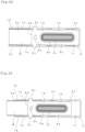
- Figs.1 and 2 show the whole constitution of the replacement lead case viewed from the front side of the cover member 1 and the back side of the case body 2.
- the cover member 1 and the case body 2 are made of resin material, and an inner lid body 3 described later which is attached to the case body 2 and covered with the cover member 1 is similarly made of resin material.
- the case body 2 and the inner lid body 3 are slidably attached to the cover member 1 along the longitudinal direction of the cover member 1 to form a replacement lead case.
- one end of the case body 2 in the longitudinal direction along which a lid body 2e, which will be described later, is advanced from the cover member 1 is referred to as a tip portion for convenience of explanation, and the other end is referred to as a rear portion.
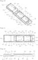
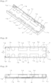
- Figs. 10 through 19 show the single part configuration of the case body 2, the inner lid body 3, and the cover member 1, and the detailed configuration of each part will be described based on the drawings showing the single part configurations.
- Figs.10 to 12 show the case body 2, and the case body 2 is formed with a rear face plate 2a and right and left leg plates 2b to have a U shape cross-section perpendicular to the longitudinal direction, and the inner space enclosed in the U-shape forms a replacement lead accommodation room 2c.
- the lid body 2e at the tip portion and a case part 2f at the rear portion are formed through the bendable thin-walled portion 2d which is formed near the tip portion in the longitudinal direction of the rear plate 2a.
- a blocking plate 2g is formed on the lid body 2e to close the tip portion of the lid body 2e by connecting the right and left leg plates 2b
- a rear blocking plate 2h is formed at the rear portion of the case part 2f to close the rear portion of the case part 2f by connecting right and left leg plates 2b.
- a guide 2j is respectively formed outside the right and left leg plates 2b of the lid body 2e, protruding like a rail along the longitudinal direction. As shown in Fig. 12 , at the tip portion side of the lid body 2e, the guide 2j has a parallel region 2j1 that is parallel to the rear plate 2a, and an inclined region 2j2 following the parallel region 2j1 is formed, leaving from the rear plate 2a as toward the thin-walled portion 2d.
- the parallel region 2j1 and the inclined region 2j2 of the guides 2j operate so as to cause the lid body 2e to pivot motion of warping toward the rear side through the thin-walled portion 2d, with sliding on the sliding body 1g provided on the cover member 1 along with the sliding action of advancing the lid body 2e of the case body 2 from the tip portion of the cover member 1 which will be described later.
- fitting recesses 2k are formed for attaching the inner lid body 3 described below at a position nearly the center of the longitudinal direction and further at a position close to the lid body 2e.
- a pair of sliding protrusions 2m is formed along the longitudinal direction of the case body 2 on both outer sides of the right and left leg plates 2b of case part 2f.
- the sliding protrusion 2m is engaged with a case support 1d described below on the cover member 1, and the case body 2 is supported slidably in the longitudinal direction.
- a rib-like clicking protrusion 2n is formed, and when the cover member 1 is slid against the case body 2, the clicking protrusion moves over a clicking body 1f so that the click action is generated. Accordingly, the click action is also generated when the case body 2 is returned to the cover member 1.
- multiple protrusions 2p are formed to avoid surface contact with the stored replacement leads so as to be perpendicular to the longitudinal direction of the case body 2.
- the multiple protrusions 2p prevent the replacement leads L from being adsorbed to the inner surface of the replacement lead accommodation room 2c of the case body made of resin material by static electricity.
- a concave part 2q is formed at the rear half portion along the longitudinal direction as shown in Fig. 2 , a group 2r of a large number of line protrusions is formed, being arrayed in a direction orthogonal to the longitudinal direction of the case body 2 in the concave part 2q.
- An arrow mark 2s is formed at the tip portion side of the concave part 2q.
- the arrow mark 2s shows the sliding direction of the case body 2 relative to the cover member 1, and the group of linear protrusions 2r functions as an anti-slip device to the finger at the sliding operation.
- Inward ribs 2t are formed each toward the inside of the case body 2 on the right and left leg plates 2b of the case body 2.
- the inward rib 2t generates a fitting force of the inner lid body 3 against the case body 2 by filling the gap between the case body 2 and the inner lid body 3 by contacting the side edge of the inner lid body when the inner lid body 3 described later is attached to the case body 2.
- This structure improves the fixing force because claws become unremovable when disassembled.
- Respectively three inclined protrusions 2u are integrally formed with the case body 2 along the upper edge, the same plane as the fitting recess 2k, so to say, of the right and left leg plates 2b on the case part 2f side of the case body 2.
- the protrusion plane of each of the inclined protrusions 2u inclines inward from the outside of the case part 2f.
- mountain-like protrusions 2v are formed respectively opposing each other on the inner surface of the right and left leg plates 2b, close to the inclined protrusion 2u at the front end side and back end side of the case part 2f.
- rib-like protrusions 2w are also formed respectively opposing each other inside the right and left leg plates 2b on the lid body 2e side of the case body 2.
- any of the inclined protrusions 2u, mountain-like protrusions 2v, and rib-like protrusions 2w function to prevent replacement leads particularly from breaking when replacement lead cases are assembled by an automatic assembly machine, in a state where a predetermined number of replacement leads are stored in the replacement lead accommodation room 2c of the case body 2.
- a predetermined number of replacement leads are charged, aligning to the longitudinal direction of the case body 2, in the replacement lead accommodation room 2c of the case body 2 placed on a horizontal plane. Then a process step accompanies fitting the inner lid body 3 to the case body 2 by pressing the inner lid body 3 from the above to the case body 2 being in the above state. Further, by placing the cover member 1 over the inner lid body 3 to cover the upper portion thereof, the replacement lead case as goods is assembled, in which the leg plates 2b of the case body 2 are housed inside the outer leg plates 1b of the cover member 1 and the case body 2 is slidably supported against the cover member 1.
- the mountain-like protrusion 2v and the rib-like protrusion 2w function as a guide to lead the replacement leads L, fed in the replacement lead accommodation room 2c, to the central area of the replacement lead accommodation room 2c without touching the right and left leg plates 2b.
- This function prevents the pair of right and left protection plates 3b formed in the inner lid body 3 from pinching the tip end of the replacement leads fed in the replacement lead accommodation room 2c in the process of fitting the inner lid body 3 to the case body 2. This action prevents the lead breakage of the replacement leads L and the occurrence of defectiveness of goods as the replacement lead case.
- Figs. 13 through 16 show the single part configuration of the inner lid body, which is attached to the right and left leg plates 2b of the case body 2 and covers the replacement lead accommodation room 2c at the front side.
- the inner lid body 3 is formed flat, and rectangular-shaped fitting protrusions 3a are respectively formed at the center of the longitudinal direction thereof and near the tip portion.
- the fitting protrusions 3a are fitted to the inner lid body concave portions 2k formed in the case body 2 to position the inner lid body 3 to the case body 2 and are attached to cover the replacement lead accommodation room 2c of the case body 2 at the front side.
- the pair of protection plates 3b formed at the tip portion of the inner lid body 3 is disposed to position over from the thin-walled portion 2d of the case body 2 to the lid body 2e inside the right and left leg plates 2b of the case body 2.
- this configuration allows effectively overcoming the problem of pinching the replacement leads L between the leg plate 2b on the lid body 2e warping to the rear and the leg plate 2b of the case part 2f when the lid body 2e advanced by the sliding action is returned to the inside of the cover member 1.
- a pair of spacers 3c formed protruding on the inner surface of the inner lid body 3 act to maintain a certain distance between the inner lid body 3 and the rear face plate 2a of the cover member 1 at the back end of the inner lid body 3.
- multiple protrusions 3d are formed on the inner surface of the inner lid body 3 in the direction perpendicular to the longitudinal direction of the inner lid body 3.
- the multiple protrusions 3d prevent the replacement lead L from surface contacting with the inner lid body 3 made of a resin, which covers the replacement lead accommodation room 2c of the case part 2f from the front side and prevents the replacement leads L from sticking to the inner lid body 3 by adsorbing due to static electricity.
- a rib-like stopper 3e protruding from the inner surface of the inner lid body 3 is formed in the immediate vicinity of the pair of spacers 3c on the inner lid body 3.
- the stopper 3e locates just in front of the gap formed between the case body 2 and the rear end of the inner lid body 3 and functions to prevent the replacement leads L stored in the replacement lead accommodation room 2c from coming out from the replacement lead case.
- Fig.16 is a perspective view of the inner lid body 3 from the outside.
- the two ribs 3f for sliding locate on the outer surface of the inner lid body 3.
- the two ribs for sliding 3f function to obtain an appropriate sliding resistance when the ribs 3f for sliding slide along the longitudinal direction against a matte-finished surface formed on the inner bottom face 1m of the cover member 1, described later.
- Figs. 17 through 19 show a single part configuration of the cover member 1.
- the cover member 1 has a U-shaped cross-section perpendicular to the longitudinal direction composed of a front face plate 1a and right and left outer leg plates 1b. At the end portion of the cover member 1, a rear leg plate 1c is formed, connecting the right and left leg plates 1b. Covering the replacement lead accommodation room 2c of the cover member 1 with front face plate 1a and also positioning the right and left leg plates 2b of the case body 2 inside the right and left outer leg plates 1b, whereby the case body 2 is supported slidably in the longitudinal direction.
- Case supports 1d facing each other inward are formed at two positions along the longitudinal direction of the edge portion of the right and left outer leg plates. By supporting the right and left sliding protrusions 2m formed on the leg plates 2b of the case body 2, the case supports hold the case body 2 slidably and function to prevent the case body from coming off from the cover member 1.
- a pair of sliding protrusions 1e are formed facing each other on the inner surface of the right and left outer leg plates 1b near the rear part.
- the rib-shaped clicking protrusions 2n formed on the case body 2 climb over the sliding protrusions forward, causing the sliding protrusions 1e to generate a clicking action when the case body 2 is set to an open state.
- a pair of clicking bodies 1f are formed facing each other.
- the rib-like clicking protrusions 2n formed on the case body 2 get over backward, and the clicking body 1f generates a click action.
- a pair of sliding bodies 1g are formed, protruding facing each other.
- the sliding body 1g function to warp the cover 2e toward the rear plate, being in contact with the parallel region 2j1 and the inclined region 2j2 of the guide 2j formed on the lid body 2e. The details of the action thereof will be described later based on Figs. 4 through 7 .
- a pair of stoppers 1h are formed slightly closer to the backside of the sliding bodies 1g at the tip portion of the cover member 1, facing each other.
- the pair of the stoppers 1h stops the sliding action of the case body 2 by abutting the tip portion (See Fig. 7 ) of the sliding protrusion 2m formed on the leg plates 2b of the case 2 when the lid body 2e is fully opened by sliding action of the case body 2.
- the pair of stoppers 1h returns the lid body 2e warped to the rear plate to a state along the longitudinal direction of the case body 2 while the sliding bodies 1g contact with a returning guide 2j3 of the guide 2j when the sliding action brings back the case body 2 into the cover member 1.
- the details of the action thereof will be described later based on Figs. 4 through 7 .
- the inner bottom face 1m of the cover member 1 is formed to be a matte-finished surface.
- the rib 3f for sliding formed on the outer surface of the inner lid body 3 described above slides on the matte-finished surface formed on the inner bottom face 1m of the cover member 1 along the longitudinal direction of the rib 3f.
- the matte-finished surface formed on the inner bottom face 1m of the cover member 1 preferably has an arithmetic average roughness (Ra) ranging from 5 um to 50 um.
- Ra arithmetic average roughness
- the arithmetic average roughness (Ra) in the range of 10 um to 25 um is even more preferable in that excellent mold releasing property and transferability of the metal mold surface are obtainable.
- the matte-finished surface may be obtainable through etching, sandblasting, and non-mirror polishing to the metal mold. Further, the matte-finished surface is also achievable by leaving the surface of the mold after discharge processing without polishing.
- the arithmetic average roughness (Ra) of the matte-finished surface denotes the arithmetic average roughness (Ra) defined by JIS (Japanese Industrial Standards) B0601:1980.
- the surface roughness is measured using a device SJ-301 manufactured by Mitutoyo Corporation.
- the detaching force of the cover member from the case body is not less than 15 N, the cover member is not detached easily from the case body, and the falling of the parts is prevented.
- a circular-shaped recess 1k is formed at approximately the center of the cover member 1, as shown in Fig. 1 .
- the recess 1k and the group of linear protrusions 2r on the case body 2 allow smooth slide operation by relatively sliding the case body 2 by putting the thumb on the recess 1k and also the indexing finger on the group of linear protrusions 2r when operated to slide the case body 2 against the cover member 1.
- matching the color of the resin forming the case body 2 to the color of the replacement lead L housed in the replacement lead case nearly the same may allow the user to identify the color of the lead housed in the replacement lead case by the coloring of the blocking plate 2g.
- Varying the color density of the resin forming the case body 2 in accordance with the hardness of the replacement lead L stepwise allows the user to identify the hardness by the color density of the blocking plate 2g.
- the color thereof is defined as within ten in hues, and within three in lightness and saturation in the Munsell color system.
- the density is to be the measurement results of the density of the surface of the parts by measuring with a densitometer such as sakura DENSITOMETER PDA-65 manufactured by KONISHIROKU PHOTO INDUSTRY CO., LTD.
- the hardness of the leads is to be the hardness measured by the method defined following JIS S 6005:2007.
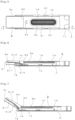
- Figs. 3 through 9 illustrate the open and close action of the lid body 2e mainly when the case body 2 is slid against the cover member 1.
- Fig. 3 is a central cross-sectional view of the case body 2, to which the inner lid body 3 is attached, housed in the cover member 1 (viewed from the a-a line of Fig. 2)
- Fig. 4 is a cross-sectional view of the same of Fig. 3 along one of the guides 2j formed on the lid body 2e (viewed from the b-b line of Fig. 2 ).
- Fig. 5 illustrates the lid body 2e of the case body 2 protruding from the tip portion of the cover member 1 by about half the length dimension of the lid body 2e.
- Fig. 6 shows the lid body 2e in the above situation.
- the sliding body 1g slides in contact with the parallel region 2j1 of the guide 2j formed on the lid body 2e, which allows advancing the lid body 2e from the tip portion of the cover member 1 without causing pivoting action to the lid body 2e.
- the sliding body 1g is slightly in contact with the inclined region 2j2 of the guide 2j, and thereby the lid body 2e is in a state warping toward the backside slightly through the thin-walled portion 2d.
- the lid body 2e can be advanced from the tip portion of the cover member 1 without causing pivoting action to the lid body 2e, the flying out and falling of the replacement leads in the replacement lead case can be prevented even if the replacement lead case is unintentionally tilted.
- Fig. 7 shows the lid part 2e being fully opened by further advancing the lid part 2e from the cover member 1.
- the sliding body 1g slides along the inclined region 2j2 of the guide 2j as the cover member 1 is advanced, so that the lid body 2e is given a rapid pivot motion toward the backside through the thin-walled portion 2d.
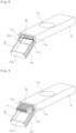
- Figs. 8 and 9 show the appearance configuration of the replacement lead case fully opened
- Fig. 9 shows the situation where replacement leads are housed in the case.
- the sliding body 1g is in contact with the rear portion of the inclined region 2j2 of the guide 2j, and in this state, the lid body 2e can be further warped through the thin-walled portion with a finger, for example, as much as the user like.
- the lid body 2e When the lid body 2e is slid to return into the cover member 1 from the fully opened state of the lid body 2e as shown in Figs. 7 to 9 , as shown in Fig. 6 , for example, the return guide 2j3 of the guide 2j slides on the stopper 1h of the case 1.
- the lid body 2e warped backward is housed into the cover member 1 while being returned into the state along the longitudinal direction of the case body 2.
- the return guide 2j3 of the guide 2j is in contact with the stopper 1h on the case body 1 side; thus the lid body 2e maintains the closed state.
- Fig. 20 is an enlarged perspective view of an enclosed region by a dot-dashed line j in Fig. 14 , and a pair of slopes 3g is formed on the inner surface of the rectangular-shaped fitting protrusion 3a.
- Forming the pair of slopes 3g on the inner surface of the rectangular-shaped fitting protrusion 3a described above allows for effectively preventing positional displacement of the inner lid body 3 along the longitudinal direction against the case body 2 when assembling.
- Fig. 21 is a partially enlarged view of the state in which the back side corner of the case body 2, surrounded by the dotted line m shown in Fig. 11 , is attached to the corner of the cover member 1 surrounded by the dotted line n shown in Figure 18 .
- the clicking body 1f formed on the cover member 1 has a gentle slope along the longitudinal direction, and the sliding protrusion 2n is formed to be a trapezoid with a flat surface 2y at its top part.
- the feeling of resistance when operated can be reduced at the moment of start opening to advance the lid body 2e of the case body 2 by sliding the case body 2 against the cover member 1.
- Forming a trapezoid with a flat surface 2y at the top part of the sliding protrusion 2n of the case body 2 allows for reducing the climbing over due to the drop impact when the replacement lead case falls.
- Figs. 22 and 23 show the replacement lead case of the second embodiment viewed from the back.
- the parts corresponding to those of the first embodiment already described are shown with the same symbols. Therefore, a detailed explanation is omitted.
- operating portions 2x protruding outward of the leg plates 2b are formed on the case body 2. It is characterized in that the sliding action is achieved to advance the lid body 2e of the case body 2 from the tip portion of the cover member 1 by moving the operating portions 2x relative to the longitudinal direction of the cover member 1.
- a pair of operating portions 2x each protruding outward are formed near the thin-walled portion 2d of the right and left leg plates 2b.
- Guiding recesses 1q are formed along the right and left outer leg plates 1b by cutting out part of each of the outer leg plates 1b in the vicinity of the tip portion of the right and left out leg plates 1b of the cover member 1.
- a pair of operating portions 2x formed on the case body 2 are positioned at the guiding recess 1q and slidably disposed in the guiding recess 1q.
- the operating portions 2x By moving the operating portions 2x relative to the longitudinal direction of the cover member 1, the sliding action of advancing the lid body 2e of the case body 2 from the tip portion of the cover member 1 is possible.
- the utilization of the operating portions 2x allows for easily achieving the sliding action of the case body 2 against the cover member 1, and a replacement lead case excellent in operation can be provided.
- the case body 2 is slidably attached to the cover member 1 when the inner lid body 3 is attached to the case body 2.
- the inner lid body 3 is not always necessary and can be omitted.
- the inner lid body 3 can be connected to the rear portion of the case body 2 via a thin-walled connecting band (not shown) to form integrally. Folding back the thin-walled connecting band to assemble the inner lid body 3 to the case body 2 can reduce the number of parts, facilitate manufacturing management, and provide a replacement lead case capable of reducing cost.
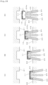
- Fig. 24 is a schematic diagram of an example of the method of molding parts of the replacement lead case including the cover member 1 or case body 2 following the order of processes (A) through (D).
- Figs. 25 through 29 show an example of the replacement lead case part 11 obtained by the molding method.
- the method of forming the replacement lead case part 11 shown in Fig. 24 is suitable for forming a replacement lead case part that is formed in a U-shaped cross-section perpendicular to the longitudinal direction by integrally providing the left and right outer leg plates 1b on both sides of the front face plate 1a, such as the cover member 1 that forms part of the replacement lead case already described. It is particularly suitable for molding replacement lead case parts in which the inward protrusions 14 of the case support 1d, for example, are integrally molded to face inward on the left and right outer leg plates 1b of the cover member 1.
- the cover member 1 and the case body 2, described above, are referred to as replacement lead case part 11, the front face plate 1a of the cover member 1 and the rear face plate 2a of the case body 2are referred to as a main face plate 12.
- the right and left outer leg plates 1b of the cover member 1 and the right and left leg plates 2b of the case body 2 are referred to as the leg plates 13, and the case supports 1d inwardly formed on the outer legs 1b of the cover member 1, sliding protrusions 1e and the stopper 1h are referred to as inward protrusions 14.
- Fig. 24 is a schematic diagram of a resin molding apparatus illustrating the status of forming the replacement lead case part 11 as the cover member 1, previously described.
- the resin molding apparatus is provided with a first mold 21 as a movable mold, a second mold 22 mounting core pins 23 forming an isosceles trapezoid, a pair of slide cores 24 which move upward along the core pins 23 in an inclination direction against the mold opening direction of the first mold 21 against the second mold 22, and an ejector pin 25 which moves upward in the same direction as the mold opening direction of the first mold 21 against the second mold 22.
- Fig. 24(A) to 24(D) show the status after opening the first mold 21 from the second mold 22.
- the resin is injected into the cavity where the first mold is closed with the second mold.
- the cavity is formed in a space surrounded by the first mold 21, the second mold 22, the core pins 23, the slide core 24, and the ejector pin 25, which compose the resin injection apparatus shown in Fig. 24(B) .
- Fig. 24(B) illustrates the initial state where the pair of slide cores 24 and the ejector pin 25 move simultaneously to the opening direction of the first mold 21.
- the movement allows the inwardly protruding portion 14 of the replacement lead case part 11 to be released from the recesses 24a, which are respectively formed outwardly in the vicinity of the tip of the slide cores 24, and the replacement lead case part 11 is received by the tip of the ejector pin 25.
- the inward protrusions 14 as an undercut formed on the replacement lead case part 11 can be vertically released from the slide cores 24. Therefore, the resin-formed replacement lead case part 11 is taken out without difficulty by a robot arm (not shown) or other means, as shown in Fig. 24(D) .
- the release of the replacement lead case part 11 is accompanied by the movement of the slide cores 24 toward the central part of the replacement lead case part 11. With this movement, the inward protrusions 14 integrally formed with the replacement lead case part 11 can smoothly be released from the slide cores 24 and received by the ejector pin 25.
- the replacement lead case part 11 having inward protrusions 14 can be released without forcibly pulling out, and replacement lead case part 11 can be obtained to prevent from deformation of the inward protrusions 14 due to forcibly pulling out.
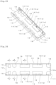
- Figs. 25 through 29 show examples of replacement lead case part 11 obtained by the forming method, and this part corresponds to the cover member 1 described above.
- rectangular first step portions 16 having large and small protruding steps due to injection molding on the inner bottom face 12a are formed at six locations along the right and left leg plates 13 except for the central portion along the longitudinal direction of the inner bottom face 12a.
- second step portions 17 having steps due to injection molding on the inner side surfaces 13a are formed continued from the step portions 16.
- third step portions 18, which have a concavo-convex direction different from that of the first step portion 16, that is, having a semi-cylindrical shape molded recessed against the inner bottom face 12a are formed at four locations deviated from the first step portions 16.
- the inner bottom face 12a of the replacement case parts 11 described above is formed by the top surface of the core pins 23 shown in Fig. 24 .
- the top faces of a pair of slide cores 24 will mold the first step portion 16.
- the second step portion 17 will be formed by flat recessed portions (not shown) formed on both outer sides of the top edge in the core pins 23.
- the third step portion 18 will be formed by the upper-end face of the ejector pin 25.
- the first step portion 16 is molded protruding against the inner bottom face 12a, so that when the replacement case part 11 is released from the slide core, the upper end of the slide core 24 slides along the face of the first step portion 16.
- product defects can be prevented, such as slipping scratches onto the inner bottom face 12a of the replacement case parts 11 due to the movement of the slide core 24 accompanied by the mold releasing.
- the third step portion 18 of the replacement case part 11 is recess-step molded to the inner bottom face 12a, and thus the replacement case part 11 released from the slide core 24 can be received in a stable posture by the ejector pin 25 in the recess step-molded third step portion 18.
Landscapes
- Engineering & Computer Science (AREA)
- Mechanical Engineering (AREA)
- Ceramic Engineering (AREA)
- Casings For Electric Apparatus (AREA)
- Packaging Of Annular Or Rod-Shaped Articles, Wearing Apparel, Cassettes, Or The Like (AREA)
- Purses, Travelling Bags, Baskets, Or Suitcases (AREA)
- Rigid Containers With Two Or More Constituent Elements (AREA)
- Cartons (AREA)
- Vehicle Step Arrangements And Article Storage (AREA)
Abstract
Description
- This invention relates to a replacement lead case that houses writing leads to be used in mechanical pencils and others.
- A replacement lead case to be used in mechanical pencils and others is often composed of two components: a case body with a bottom and a lid body detachably equipped at an opening of the case body.
-
Patent literature 1 discloses a replacement lead case, for example, constituting two parts that are a case body made of a resin material and a lid body made of a resin material. Sliding the lid body in the direction perpendicular to the longitudinal direction of the replacement lead case releases the opening of the case body (the opening for taking out the replacement lead). - In this case, the position of the lid body against the opening of the case body can be set up in two steps, for example. This structure allows the user to set the opening to have an appropriate area for taking out the replacement leads.
- Further,
patent literature 2 discloses a replacement lead case similarly constituting two parts: a case body made of a resin material and a lid body made of a resin material. The lid body is detachably attached to the opening of the case body with a bottom. - The opening (the opening for taking out the replacement lead formed on the case body) is cut at an angle on the front side. This structure allows the user to pick up replacement leads with the fingertips, making a replacement lead case easy to use.
-
- PTL 1:
JP-A-2010-30136 - PTL 2:
JP-A-2010-173248 - In all of the replacement cases disclosed in the above patent literature, it is necessary to tilt the case body so that the replacement lead outlet faces slightly downward while the replacement lead outlet is open. The replacement leads are taken out from the case body by utilizing the replacement leads coming out to the outlet due to their gravity of themselves.
- This procedure requires a subtle operation of rocking the case body while adjusting the inclination of the case body. This operation may cause more replacement leads than necessary or all the replacement leads inside the case to come out from the replacement lead outlet and scatter on the floor; in some cases, the user is forced to pick up and return replacement leads scattered on the floor.
- This invention is made in response to the problems mentioned above of conventional replacement lead cases. The objective is to provide a replacement lead case that allows the user to easily take out the required replacement leads without directing the replacement lead outlet downward and prevents a large number of replacement leads from coming out simultaneously from the case body, whereby the problems of the conventional replacement lead cases are eliminated.
- A preplacement lead case according to the present invention for solving problems recited above is characterized in that the replacement lead case includes a case body, in which the inner space enclosed by a back plate and the right and left leg plates is used as a replacement lead accommodation room, and a lid body is formed on the tip side and a case part is on the rear side via a bendable thin-walled portion placed near the tip of the rear plate in the longitudinal direction, and a cover member which is formed in a U-shaped cross-section perpendicular to the longitudinal direction by the front face plate and the right and left outer leg plates, and in which the replacement lead accommodation room on the case body is covered by the front face plate, and which is slidably supported in the longitudinal direction by positioning the leg plates of the case body inside the outer leg plates,
wherein a guide is formed along the longitudinal direction on either one of at least one of the leg plates of the lid body or the outer leg plate of the cover member that covers the leg plate, and also a sliding body in contact with the guide is formed on either one or the other, and with the sliding action of advancing the lid body of the case body from the tip of the cover member, the sliding contact of the sliding body against the guide causes the lid body to pivot to warp the lid body toward the rear plate through the thin-walled portion. - In this case, in a preferable embodiment, it is desirable that an inner lid body is further provided, which is fixed to the right and left leg plate of the case body and covers the replacement lead accommodation room at the front face side thereof and protrusions to avoid surface contact with the stored replacement leads are formed on the inner surface of the replacement lead accommodation room side of the rear plate of the case body and the inner surface of the replacement lead accommodation room side of the inner lid body.
- Further, in the inner lid body, a pair of protection plates are desirably formed so as to respectively locate the inside of the right and left leg plates from the thin-walled portion of the case body to the lid body.
- Meanwhile, the guide is preferably formed, projecting in a rail-like form and extending along the longitudinal direction outside the leg plates of the lid body. Further, the preferred form of a locking portion is formed, protruding to be in contact with the guide at the tip portion of the cover member from which the sliding action advances the lid body. By forming an inclined region in the guide that is getting away from the rear plate from the tip end toward the thin-walled portion, the sliding action causes the lid body to pivot motion to warp toward the rear plate through the thin-walled portion.
- In this case, more preferably, at the contacting portion with the sliding body in the guide, a parallel region parallel to the rear plate is formed at the tip end side, and the inclined region is formed continuously from the parallel region. With this structure, the former half of the sliding action does not cause the lid body to pivot motion and allows it to move to advance the lid body from the tip end of the cover member, and the latter half of the sliding action causes the lid body to pivot motion to warp toward the rear plate.
- In a preferable embodiment, a blocking plate is formed to close the tip end by connecting the right and left leg plates at the tip end side of the lid body, and the blocking plate is visibly recognizably disposed at the tip end of the cover member, in a state where the lid body is accommodated in the cover member and the front face plate of the cover member is viewed from the front.
- Further, it is desirable that the case body and the cover are both made of resin material, a group of a large number of line protrusions is formed in a direction orthogonal to the longitudinal direction on the backside of the rear plate of the case body, and a circular-shaped recess, for example, is formed on the surface of the front face plate of the cover member.
- Further, it is desirable that a rib for sliding is formed along the longitudinal direction of the inner lid body on the outer surface of the inner lid body, and the inner bottom face of the cover member has a matte-finished surface.
- In another embodiment of the replacement lead case of this invention, the case body is provided with an operation part protruding outwardly from the leg plate. Moving the operation part relative to the longitudinal direction of the cover member achieves a sliding motion to advance the lid body of the case body from the tip end of the cover member.
- Due to the provision of right and left legs integrally formed on both sides of the main plate, the replacement lead case of this invention uses a member as a part of the replacement lead case, the member which is formed in a U-shaped cross-section perpendicular to the longitudinal direction and has inward projections integrally formed on the left and right leg plates facing inward the leg plates, wherein, on an inner bottom face of the main plate which is located between the right and left leg plates of the replacement lead case part, a first step portion having a step against the inner bottom face is formed along the right and left leg plates except for a central portion of the longitudinal direction of the inner bottom face.
- In one preferred embodiment, a structure is employed where on the opposing inner surfaces of the right and left leg plates, a second step portion with a step against the inner surface is formed continuously from the first step portion.
- Further, on the inner bottom face of the main plate located between the right and left leg plates, a third step portion, which has a different concavo-convex direction from the first step portion, is formed at a position where it does not overlap the first step. In this case, a structure is adopted that the first step portion is preferably formed protruding from the inner bottom face, and the third step portion is formed recessed to the inner bottom face.
- According to the replacement lead case of the present invention described above, a replacement lead case is formed by slidably mounting the case body, which is formed of a lid body and a case part via a bendable thin-walled portion, to the inside of the cover member. By forming a guide and sliding member slidable to each other by sliding action on one or the other of the lid body and the cover member, the sliding action causes the lid body to pivot motion to warp toward the rear face plate.
- Consequently, the tip portions of the replacement leads are exposed projecting from the case part by the pivot motion of the lid body due to the thin-walled, whereby necessary replacement leads can be easily taken out.
- Accordingly, since this allows taking out replacement leads without tilting the case body slightly downward, a replacement lead case can be provided which overcomes the problem conventional ones have where a lot of replacement leads fly out simultaneously from the case body, for example.
- An inner lid body is additionally attached to the case body to cover the replacement lead accommodation room on the front side.
Protrusions are formed on the inner surfaces of the case body and the inner lid body to avoid surface contact with the replacement leads, which effectively eliminates the problem of replacement lead sticking to the inside of the replacement lead accommodation room due to static electricity. With this structure, compared to the case where protrusions are formed respectively on opposing surfaces in a single part, forming the case body and the inner lid body with two parts allows for avoiding the problem of causing damage to opposing protrusions when forcibly extracting at releasing from the mold. - On the inner lid body, a pair of protection plates located from the thin-walled of the case body to the lid body are respectively formed on the inner side of the right and left leg of the case body. This structure effectively overcomes the problem of replacement leads being pinched between the leg plate of the lid body warping toward the backside and the leg plate of the case when the lid body advanced by the sliding action is retracted into the cover member.
- Other advantageous effects of the invention will be explained each time in the paragraphs of the embodiment for carrying out the invention, together with the description of the examples.
-
-
Fig. 1 is a front view of a replacement lead case of the first embodiment according to the present invention; -
Fig. 2 is a back view of the replacement lead case thereof. -
Fig. 3 is a cross-sectional view of the replacement lead case in the arrow direction from the a-a line ofFig. 2 ; -
Fig. 4 is a cross-sectional view of the replacement lead case in the arrow direction from the b-b line ofFig. 2 ; -
Fig. 5 is a back view of the replacement lead case in the state where a lid body is advanced halfway viewed from a case body; -
Fig. 6 is a cross-sectional view of the replacement lead case in the arrow direction from the c-c line ofFig. 5 ; -
Fig. 7 is a cross-sectional view illustrating the state where the lid body is fully opened further from the state shown inFig. 6 ; -
Fig. 8 is a perspective view of the replacement lead case in the state where the lid body is fully opened, viewed from a cover member; -
Fig. 9 is a perspective view of the replacement lead case in the same state as shown inFig. 8 where replacement leads are housed, viewed from a cover member; -
Fig. 10 is a perspective view illustrating the single part configuration of a case body constituting the replacement lead case; -
Fig. 11 is a front view thereof; -
Fig. 12 is a top view thereof; -
Fig. 13 is a perspective view illustrating the single part configuration of an inner lid body; -
Fig. 14 is a front view of the single part configuration of an inner lid body; -
Fig. 15 is a cross-sectional view of the single part configuration of an inner lid body in the arrow direction from the d-d line ofFig. 14 ; -
Fig. 16 is a perspective view of the inner lid body viewed from the outside; -
Fig. 17 is a perspective view illustrating the single part configuration of the cover member; -
Fig. 18 is a front view of the single part configuration of the cover; -
Fig. 19 is a cross-sectional view of the single part configuration of the cover in the arrow direction from the e-e line ofFig. 18 ; -
Fig. 20 is an enlarged perspective view of an enclosed region by a dot-dashed line j of the single part configuration of the inner lid body inFig. 14 ; -
Fig. 21 is an enlarged view of the backside corner of the replacement lead case; -
Fig. 22 is a back view of a replacement lead case of the second embodiment; -
Fig. 23 is a back view illustrating the replacement lead case in a state where a lid body is advanced halfway.; -
Fig. 24 is a schematic view illustrating a forming method of the parts of the replacement lead case in a processing order of (A) to (D); -
Fig. 25 is a perspective view illustrating parts of the replacement lead case obtained by the method shown inFig. 24 ; -
Fig. 26 is a front view of parts of the replacement lead case obtained by the method shown inFig. 24 ; -
Fig. 27 is a cross-sectional view viewed in an arrow direction from the f-f line inFig. 26 ; -
Fig. 28 is a cross-sectional view viewed in an arrow direction from the g-g line inFig. 26 ; and -
Fig. 29 is a cross-sectional view viewed in an arrow direction from the h-h line inFig. 26 . - A replacement lead case according to the present invention will be described based on drawings.
-
Figs. 1 through 21 show a replacement lead case of the first embodiment,Figs. 22 and 23 show a replacement lead case of the second embodiment.Figs. 24 through 29 show an example of a method of forming parts of the replacement lead case and replacement lead cases to be obtained. - First, the first embodiment of the replacement lead case will be described based on
Figs. 1 through 21 . -
Figs.1 and 2 show the whole constitution of the replacement lead case viewed from the front side of thecover member 1 and the back side of thecase body 2. - In this embodiment, the
cover member 1 and thecase body 2 are made of resin material, and aninner lid body 3 described later which is attached to thecase body 2 and covered with thecover member 1 is similarly made of resin material. Thecase body 2 and theinner lid body 3 are slidably attached to thecover member 1 along the longitudinal direction of thecover member 1 to form a replacement lead case. - In the following, one end of the
case body 2 in the longitudinal direction along which a lid body 2e, which will be described later, is advanced from thecover member 1 is referred to as a tip portion for convenience of explanation, and the other end is referred to as a rear portion. -
Figs. 10 through 19 show the single part configuration of thecase body 2, theinner lid body 3, and thecover member 1, and the detailed configuration of each part will be described based on the drawings showing the single part configurations. -
Figs.10 to 12 show thecase body 2, and thecase body 2 is formed with a rear face plate 2a and right and left leg plates 2b to have a U shape cross-section perpendicular to the longitudinal direction, and the inner space enclosed in the U-shape forms a replacement lead accommodation room 2c. - The lid body 2e at the tip portion and a case part 2f at the rear portion are formed through the bendable thin-walled portion 2d which is formed near the tip portion in the longitudinal direction of the rear plate 2a.
- Further, a blocking plate 2g is formed on the lid body 2e to close the tip portion of the lid body 2e by connecting the right and left leg plates 2b, and a rear blocking plate 2h is formed at the rear portion of the case part 2f to close the rear portion of the case part 2f by connecting right and left leg plates 2b.
- A
guide 2j is respectively formed outside the right and left leg plates 2b of the lid body 2e, protruding like a rail along the longitudinal direction. As shown inFig. 12 , at the tip portion side of the lid body 2e, theguide 2j has a parallel region 2j1 that is parallel to the rear plate 2a, and an inclined region 2j2 following the parallel region 2j1 is formed, leaving from the rear plate 2a as toward the thin-walled portion 2d. - The parallel region 2j1 and the inclined region 2j2 of the
guides 2j operate so as to cause the lid body 2e to pivot motion of warping toward the rear side through the thin-walled portion 2d, with sliding on the sliding body 1g provided on thecover member 1 along with the sliding action of advancing the lid body 2e of thecase body 2 from the tip portion of thecover member 1 which will be described later. - On the left and right leg plate 2b in the case part 2f, fitting recesses 2k are formed for attaching the
inner lid body 3 described below at a position nearly the center of the longitudinal direction and further at a position close to the lid body 2e. - Further, a pair of sliding
protrusions 2m is formed along the longitudinal direction of thecase body 2 on both outer sides of the right and left leg plates 2b of case part 2f. The slidingprotrusion 2m is engaged with a case support 1d described below on thecover member 1, and thecase body 2 is supported slidably in the longitudinal direction. - At a position near the rear portion of the right and left leg plates 2b of the case part 2f, a rib-like clicking protrusion 2n is formed, and when the
cover member 1 is slid against thecase body 2, the clicking protrusion moves over a clicking body 1f so that the click action is generated. Accordingly, the click action is also generated when thecase body 2 is returned to thecover member 1. - Further, on the inner surface of the replacement lead accommodation room 2c at the rear plate 2a of the case part 2f, multiple protrusions 2p are formed to avoid surface contact with the stored replacement leads so as to be perpendicular to the longitudinal direction of the
case body 2. The multiple protrusions 2p prevent the replacement leads L from being adsorbed to the inner surface of the replacement lead accommodation room 2c of the case body made of resin material by static electricity. - Further, on the backside of the rear plate 2a of the
case body 2, a concave part 2q is formed at the rear half portion along the longitudinal direction as shown inFig. 2 , a group 2r of a large number of line protrusions is formed, being arrayed in a direction orthogonal to the longitudinal direction of thecase body 2 in the concave part 2q. An arrow mark 2s, preferably triangular, is formed at the tip portion side of the concave part 2q. - The arrow mark 2s shows the sliding direction of the
case body 2 relative to thecover member 1, and the group of linear protrusions 2r functions as an anti-slip device to the finger at the sliding operation. - Inward ribs 2t are formed each toward the inside of the
case body 2 on the right and left leg plates 2b of thecase body 2. The inward rib 2t generates a fitting force of theinner lid body 3 against thecase body 2 by filling the gap between thecase body 2 and theinner lid body 3 by contacting the side edge of the inner lid body when theinner lid body 3 described later is attached to thecase body 2. This structure improves the fixing force because claws become unremovable when disassembled. - Respectively three inclined protrusions 2u are integrally formed with the
case body 2 along the upper edge, the same plane as the fitting recess 2k, so to say, of the right and left leg plates 2b on the case part 2f side of thecase body 2. The protrusion plane of each of the inclined protrusions 2u inclines inward from the outside of the case part 2f. - Further, mountain-like protrusions 2v are formed respectively opposing each other on the inner surface of the right and left leg plates 2b, close to the inclined protrusion 2u at the front end side and back end side of the case part 2f. Further, rib-like protrusions 2w are also formed respectively opposing each other inside the right and left leg plates 2b on the lid body 2e side of the
case body 2. - Any of the inclined protrusions 2u, mountain-like protrusions 2v, and rib-like protrusions 2w function to prevent replacement leads particularly from breaking when replacement lead cases are assembled by an automatic assembly machine, in a state where a predetermined number of replacement leads are stored in the replacement lead accommodation room 2c of the
case body 2. - Namely, for the assembly of the replacement lead case with an automatic assembly machine, a predetermined number of replacement leads are charged, aligning to the longitudinal direction of the
case body 2, in the replacement lead accommodation room 2c of thecase body 2 placed on a horizontal plane. Then a process step accompanies fitting theinner lid body 3 to thecase body 2 by pressing theinner lid body 3 from the above to thecase body 2 being in the above state. Further, by placing thecover member 1 over theinner lid body 3 to cover the upper portion thereof, the replacement lead case as goods is assembled, in which the leg plates 2b of thecase body 2 are housed inside the outer leg plates 1b of thecover member 1 and thecase body 2 is slidably supported against thecover member 1. - Accordingly, since the protruding surface of the inclined protrusion 2u is inclined to lower from the outside to the inside of the case part 2f, the placement of replacement leads, formed long and thin, is hindered on the same plane as the fitting concave 2k; this structure acts to house all the replacement leads charged in the replacement lead L accommodation room 2c of the
case body 2. - The mountain-like protrusion 2v and the rib-like protrusion 2w function as a guide to lead the replacement leads L, fed in the replacement lead accommodation room 2c, to the central area of the replacement lead accommodation room 2c without touching the right and left leg plates 2b. This function prevents the pair of right and left protection plates 3b formed in the
inner lid body 3 from pinching the tip end of the replacement leads fed in the replacement lead accommodation room 2c in the process of fitting theinner lid body 3 to thecase body 2. This action prevents the lead breakage of the replacement leads L and the occurrence of defectiveness of goods as the replacement lead case. -
Figs. 13 through 16 show the single part configuration of the inner lid body, which is attached to the right and left leg plates 2b of thecase body 2 and covers the replacement lead accommodation room 2c at the front side. - The
inner lid body 3 is formed flat, and rectangular-shaped fitting protrusions 3a are respectively formed at the center of the longitudinal direction thereof and near the tip portion. The fitting protrusions 3a are fitted to the inner lid body concave portions 2k formed in thecase body 2 to position theinner lid body 3 to thecase body 2 and are attached to cover the replacement lead accommodation room 2c of thecase body 2 at the front side. - At this time, the pair of protection plates 3b formed at the tip portion of the
inner lid body 3 is disposed to position over from the thin-walled portion 2d of thecase body 2 to the lid body 2e inside the right and left leg plates 2b of thecase body 2. - As recited in the section about the advantageous effects, this configuration allows effectively overcoming the problem of pinching the replacement leads L between the leg plate 2b on the lid body 2e warping to the rear and the leg plate 2b of the case part 2f when the lid body 2e advanced by the sliding action is returned to the inside of the
cover member 1. - A pair of spacers 3c formed protruding on the inner surface of the
inner lid body 3 act to maintain a certain distance between theinner lid body 3 and the rear face plate 2a of thecover member 1 at the back end of theinner lid body 3. - Further, multiple protrusions 3d are formed on the inner surface of the
inner lid body 3 in the direction perpendicular to the longitudinal direction of theinner lid body 3. The multiple protrusions 3d prevent the replacement lead L from surface contacting with theinner lid body 3 made of a resin, which covers the replacement lead accommodation room 2c of the case part 2f from the front side and prevents the replacement leads L from sticking to theinner lid body 3 by adsorbing due to static electricity. - Further, a rib-like stopper 3e protruding from the inner surface of the
inner lid body 3 is formed in the immediate vicinity of the pair of spacers 3c on theinner lid body 3. - In a state where the
inner lid body 3 is attached to thecase body 2, the stopper 3e locates just in front of the gap formed between thecase body 2 and the rear end of theinner lid body 3 and functions to prevent the replacement leads L stored in the replacement lead accommodation room 2c from coming out from the replacement lead case. -
Fig.16 is a perspective view of theinner lid body 3 from the outside. Two ribs 3f for sliding formed parallel to each other on the outer surface of theinner lid body 3. - Accordingly, in a state where the
inner lid body 3 is attached to thecase body 2, the two ribs 3f for sliding locate on the outer surface of theinner lid body 3. The two ribs for sliding 3f function to obtain an appropriate sliding resistance when the ribs 3f for sliding slide along the longitudinal direction against a matte-finished surface formed on the innerbottom face 1m of thecover member 1, described later. -
Figs. 17 through 19 show a single part configuration of thecover member 1. Thecover member 1 has a U-shaped cross-section perpendicular to the longitudinal direction composed of a front face plate 1a and right and left outer leg plates 1b. At the end portion of thecover member 1, a rear leg plate 1c is formed, connecting the right and left leg plates 1b. Covering the replacement lead accommodation room 2c of thecover member 1 with front face plate 1a and also positioning the right and left leg plates 2b of thecase body 2 inside the right and left outer leg plates 1b, whereby thecase body 2 is supported slidably in the longitudinal direction. - It is constructed that the sliding action allows the lid body 2e of the
case body 2 to advance from the tip portion of thecover member 1. - Case supports 1d facing each other inward are formed at two positions along the longitudinal direction of the edge portion of the right and left outer leg plates. By supporting the right and left sliding
protrusions 2m formed on the leg plates 2b of thecase body 2, the case supports hold thecase body 2 slidably and function to prevent the case body from coming off from thecover member 1. - Further, a pair of sliding protrusions 1e are formed facing each other on the inner surface of the right and left outer leg plates 1b near the rear part. The rib-shaped clicking protrusions 2n formed on the
case body 2 climb over the sliding protrusions forward, causing the sliding protrusions 1e to generate a clicking action when thecase body 2 is set to an open state. - Further, near the rear part inside the outer leg plates 1b, a pair of clicking bodies 1f are formed facing each other. When the
case body 2 is slid, the rib-like clicking protrusions 2n formed on thecase body 2 get over backward, and the clicking body 1f generates a click action. - On the inside of the outer leg plates 1b at the tip portion of the
cover member 1, a pair of sliding bodies 1g are formed, protruding facing each other. When thecase body 2 is slid, and the cover 2e protrudes from the tip portion of thecover member 1, the sliding body 1g function to warp the cover 2e toward the rear plate, being in contact with the parallel region 2j1 and the inclined region 2j2 of theguide 2j formed on the lid body 2e. The details of the action thereof will be described later based onFigs. 4 through 7 . - A pair of stoppers 1h are formed slightly closer to the backside of the sliding bodies 1g at the tip portion of the
cover member 1, facing each other.
The pair of the stoppers 1h stops the sliding action of thecase body 2 by abutting the tip portion (SeeFig. 7 ) of the slidingprotrusion 2m formed on the leg plates 2b of thecase 2 when the lid body 2e is fully opened by sliding action of thecase body 2. - The pair of stoppers 1h returns the lid body 2e warped to the rear plate to a state along the longitudinal direction of the
case body 2 while the sliding bodies 1g contact with a returning guide 2j3 of theguide 2j when the sliding action brings back thecase body 2 into thecover member 1. The details of the action thereof will be described later based onFigs. 4 through 7 . - On the inner
bottom face 1m of thecover member 1 surrounded by the left and right outer leg plates 1b, rectangular flat protrusions 1n slightly protruding against the innerbottom face 1m, as shown inFigs. 17 and 18 , are formed intermittently along the left and right outer leg plates 1b, excluding the center of the longitudinal direction of the innerbottom face 1m. - The inner
bottom face 1m of thecover member 1 is formed to be a matte-finished surface. The rib 3f for sliding formed on the outer surface of theinner lid body 3 described above slides on the matte-finished surface formed on the innerbottom face 1m of thecover member 1 along the longitudinal direction of the rib 3f. - The matte-finished surface formed on the inner
bottom face 1m of thecover member 1 preferably has an arithmetic average roughness (Ra) ranging from 5 um to 50 um. When the value is smaller than 5 µm, the surface becomes nearly specular, and the contact resistance increases, which may cause a risk that theinner lid body 3 may not slide smoothly. When the value is more than 50 µm, mold releasing becomes difficult, and good transferability of the metal mold surface (matte-finished surface) becomes difficult to obtain. The arithmetic average roughness (Ra) in the range of 10 um to 25 um is even more preferable in that excellent mold releasing property and transferability of the metal mold surface are obtainable. - The matte-finished surface may be obtainable through etching, sandblasting, and non-mirror polishing to the metal mold. Further, the matte-finished surface is also achievable by leaving the surface of the mold after discharge processing without polishing.
- The arithmetic average roughness (Ra) of the matte-finished surface denotes the arithmetic average roughness (Ra) defined by JIS (Japanese Industrial Standards) B0601:1980. The surface roughness is measured using a device SJ-301 manufactured by Mitutoyo Corporation.
- By setting the detaching force of the cover member from the case body to be not less than 15 N, the cover member is not detached easily from the case body, and the falling of the parts is prevented.
- On the surface of the front face plate 1a of the
cover member 1, a circular-shaped recess 1k is formed at approximately the center of thecover member 1, as shown inFig. 1 . - The recess 1k and the group of linear protrusions 2r on the
case body 2 allow smooth slide operation by relatively sliding thecase body 2 by putting the thumb on the recess 1k and also the indexing finger on the group of linear protrusions 2r when operated to slide thecase body 2 against thecover member 1. - As shown in
Figs. 1 and 2 , when thecase body 2 is housed in thecover member 1, in the front view of the front face plate 1a of the cover member 1 (shown inFig. 1 ), the blocking plate 2g of the lid body 2e formed at the tip portion of thecase body 2 is visible along the tip-end cut out 1j formed at the tip portion of thecover member 1. - According to this, matching the color of the resin forming the
case body 2 to the color of the replacement lead L housed in the replacement lead case nearly the same may allow the user to identify the color of the lead housed in the replacement lead case by the coloring of the blocking plate 2g. - Varying the color density of the resin forming the
case body 2 in accordance with the hardness of the replacement lead L stepwise allows the user to identify the hardness by the color density of the blocking plate 2g. The color thereof is defined as within ten in hues, and within three in lightness and saturation in the Munsell color system. The density is to be the measurement results of the density of the surface of the parts by measuring with a densitometer such as sakura DENSITOMETER PDA-65 manufactured by KONISHIROKU PHOTO INDUSTRY CO., LTD. The hardness of the leads is to be the hardness measured by the method defined following JIS S 6005:2007. -
Figs. 3 through 9 illustrate the open and close action of the lid body 2e mainly when thecase body 2 is slid against thecover member 1. -
Fig. 3 is a central cross-sectional view of thecase body 2, to which theinner lid body 3 is attached, housed in the cover member 1 (viewed from the a-a line ofFig. 2), and Fig. 4 is a cross-sectional view of the same ofFig. 3 along one of theguides 2j formed on the lid body 2e (viewed from the b-b line ofFig. 2 ). - In the state where the
case body 2 is housed in thecover member 1 as shown inFig. 4 , the stopper 1h of thecover member 1 is in contact with the return guide 2j3 of theguide 2j, and therefore, the lid body 2e maintains the closed state along the longitudinal direction of thecover member 1. -
Fig. 5 illustrates the lid body 2e of thecase body 2 protruding from the tip portion of thecover member 1 by about half the length dimension of the lid body 2e.Fig. 6 shows the lid body 2e in the above situation. In the early stage (the former half) of protruding the lid body 2e from the tip portion of thecover member 1, the sliding body 1g slides in contact with the parallel region 2j1 of theguide 2j formed on the lid body 2e, which allows advancing the lid body 2e from the tip portion of thecover member 1 without causing pivoting action to the lid body 2e. - In the situation shown in
Fig. 6 , the sliding body 1g is slightly in contact with the inclined region 2j2 of theguide 2j, and thereby the lid body 2e is in a state warping toward the backside slightly through the thin-walled portion 2d. - As described above, in the early stage of protruding the lid body 2e, since the lid body 2e can be advanced from the tip portion of the
cover member 1 without causing pivoting action to the lid body 2e, the flying out and falling of the replacement leads in the replacement lead case can be prevented even if the replacement lead case is unintentionally tilted. -
Fig. 7 shows the lid part 2e being fully opened by further advancing the lid part 2e from thecover member 1. In the latter half of the advancing operation of the lid 2e from the state shown inFig. 6 to the state shown inFig. 7 , the sliding body 1g slides along the inclined region 2j2 of theguide 2j as thecover member 1 is advanced, so that the lid body 2e is given a rapid pivot motion toward the backside through the thin-walled portion 2d. - In the state where the lid body 2e fully opens as shown in
Fig. 7 , the tip portion of the slidingprotrusions 2m formed along the longitudinal direction of thecase body 2 comes into contact with the stopper 1h and the advancing of the lid body 2e is stopped. -
Figs. 8 and 9 show the appearance configuration of the replacement lead case fully opened, andFig. 9 shows the situation where replacement leads are housed in the case. In the state where the lid body 2e fully opens, as shown inFig. 7 , the sliding body 1g is in contact with the rear portion of the inclined region 2j2 of theguide 2j, and in this state, the lid body 2e can be further warped through the thin-walled portion with a finger, for example, as much as the user like. - As a result, the exact number of necessary replacement leads can be taken from the replacement lead case.
- When the lid body 2e is slid to return into the
cover member 1 from the fully opened state of the lid body 2e as shown inFigs. 7 to 9 , as shown inFig. 6 , for example, the return guide 2j3 of theguide 2j slides on the stopper 1h of thecase 1. The lid body 2e warped backward is housed into thecover member 1 while being returned into the state along the longitudinal direction of thecase body 2. - Further, in the state where the lid body 2e is entirely housed in the
cover member 1 as shown inFig. 4 , the return guide 2j3 of theguide 2j is in contact with the stopper 1h on thecase body 1 side; thus the lid body 2e maintains the closed state. - When the lid body 2e is returned to the
cover member 1 from the fully opened state, a problem may arise that the replacement leads L are broken by pinching part of the replacement leads L housed in the case between the lid body 2e made via the thin-wall portion 2d and each of leg plates 2b formed on the case part 2f. - However, as shown in
Fig. 8 , the problem of breaking replacement leads L can be avoided because the pair of protection plates 3b formed at the tip portion of theinner lid body 3 is located inside each leg plate 2b of the lid body 2e and the case part 2f. -
Fig. 20 is an enlarged perspective view of an enclosed region by a dot-dashed line j inFig. 14 , and a pair of slopes 3g is formed on the inner surface of the rectangular-shaped fitting protrusion 3a. - Forming the pair of slopes 3g on the inner surface of the rectangular-shaped fitting protrusion 3a described above allows for effectively preventing positional displacement of the
inner lid body 3 along the longitudinal direction against thecase body 2 when assembling. -
Fig. 21 is a partially enlarged view of the state in which the back side corner of thecase body 2, surrounded by the dotted line m shown inFig. 11 , is attached to the corner of thecover member 1 surrounded by the dotted line n shown inFigure 18 . - As shown in
Fig. 21 , the clicking body 1f formed on thecover member 1 has a gentle slope along the longitudinal direction, and the sliding protrusion 2n is formed to be a trapezoid with a flat surface 2y at its top part. - Since the clicking body 1f of the
cover member 1 and the sliding protrusion 2n of thecase body 2 both have a gentle slope, the feeling of resistance when operated can be reduced at the moment of start opening to advance the lid body 2e of thecase body 2 by sliding thecase body 2 against thecover member 1. - Forming a trapezoid with a flat surface 2y at the top part of the sliding protrusion 2n of the
case body 2 allows for reducing the climbing over due to the drop impact when the replacement lead case falls. -
Figs. 22 and 23 show the replacement lead case of the second embodiment viewed from the back. The parts corresponding to those of the first embodiment already described are shown with the same symbols. Therefore, a detailed explanation is omitted. - In the replacement lead case of the second embodiment, operating portions 2x protruding outward of the leg plates 2b are formed on the
case body 2. It is characterized in that the sliding action is achieved to advance the lid body 2e of thecase body 2 from the tip portion of thecover member 1 by moving the operating portions 2x relative to the longitudinal direction of thecover member 1. - In the
case body 2, a pair of operating portions 2x each protruding outward are formed near the thin-walled portion 2d of the right and left leg plates 2b. - Guiding recesses 1q are formed along the right and left outer leg plates 1b by cutting out part of each of the outer leg plates 1b in the vicinity of the tip portion of the right and left out leg plates 1b of the
cover member 1. In a state where thecase body 2 is attached to thecover member 1, a pair of operating portions 2x formed on thecase body 2 are positioned at the guiding recess 1q and slidably disposed in the guiding recess 1q. - Accordingly, by moving the operating portions 2x relative to the longitudinal direction of the
cover member 1, the sliding action of advancing the lid body 2e of thecase body 2 from the tip portion of thecover member 1 is possible. The utilization of the operating portions 2x allows for easily achieving the sliding action of thecase body 2 against thecover member 1, and a replacement lead case excellent in operation can be provided. - In the replacement lead case according to the first and second embodiments, the
case body 2 is slidably attached to thecover member 1 when theinner lid body 3 is attached to thecase body 2. Theinner lid body 3 is not always necessary and can be omitted. - In the case the
inner lid body 3 is used, theinner lid body 3 can be connected to the rear portion of thecase body 2 via a thin-walled connecting band (not shown) to form integrally. Folding back the thin-walled connecting band to assemble theinner lid body 3 to thecase body 2 can reduce the number of parts, facilitate manufacturing management, and provide a replacement lead case capable of reducing cost. -
Fig. 24 is a schematic diagram of an example of the method of molding parts of the replacement lead case including thecover member 1 orcase body 2 following the order of processes (A) through (D).Figs. 25 through 29 show an example of the replacementlead case part 11 obtained by the molding method. - First, the method of forming the replacement
lead case part 11 shown inFig. 24 is suitable for forming a replacement lead case part that is formed in a U-shaped cross-section perpendicular to the longitudinal direction by integrally providing the left and right outer leg plates 1b on both sides of the front face plate 1a, such as thecover member 1 that forms part of the replacement lead case already described. It is particularly suitable for molding replacement lead case parts in which theinward protrusions 14 of the case support 1d, for example, are integrally molded to face inward on the left and right outer leg plates 1b of thecover member 1. - In the following description of a molding method for replacement lead case parts, the
cover member 1 and thecase body 2, described above, are referred to as replacementlead case part 11, the front face plate 1a of thecover member 1 and the rear face plate 2a of the case body 2are referred to as amain face plate 12. Further, the right and left outer leg plates 1b of thecover member 1 and the right and left leg plates 2b of thecase body 2 are referred to as theleg plates 13, and the case supports 1d inwardly formed on the outer legs 1b of thecover member 1, sliding protrusions 1e and the stopper 1h are referred to asinward protrusions 14. -
Fig. 24 is a schematic diagram of a resin molding apparatus illustrating the status of forming the replacementlead case part 11 as thecover member 1, previously described. - The resin molding apparatus is provided with a
first mold 21 as a movable mold, asecond mold 22 mounting core pins 23 forming an isosceles trapezoid, a pair ofslide cores 24 which move upward along the core pins 23 in an inclination direction against the mold opening direction of thefirst mold 21 against thesecond mold 22, and anejector pin 25 which moves upward in the same direction as the mold opening direction of thefirst mold 21 against thesecond mold 22. -
Fig. 24(A) to 24(D) show the status after opening thefirst mold 21 from thesecond mold 22. In the preceding resin injection process, the resin is injected into the cavity where the first mold is closed with the second mold. - In this case, the cavity is formed in a space surrounded by the
first mold 21, thesecond mold 22, the core pins 23, theslide core 24, and theejector pin 25, which compose the resin injection apparatus shown inFig. 24(B) . -
Fig. 24(B) illustrates the initial state where the pair ofslide cores 24 and theejector pin 25 move simultaneously to the opening direction of thefirst mold 21. - As shown in
Fig. 24(C) , from the initial state above, the pair ofslide cores 24 and theejector pin 25 further move upward without changing their relative height. This movement causes the tip portion of the pair of theslide cores 24 to move to come nearer to each other toward the central part of the replacementlead case part 11. - The movement allows the inwardly protruding
portion 14 of the replacementlead case part 11 to be released from the recesses 24a, which are respectively formed outwardly in the vicinity of the tip of theslide cores 24, and the replacementlead case part 11 is received by the tip of theejector pin 25. - In the state shown in
Fig. 24(C) , theinward protrusions 14 as an undercut formed on the replacementlead case part 11 can be vertically released from theslide cores 24. Therefore, the resin-formed replacementlead case part 11 is taken out without difficulty by a robot arm (not shown) or other means, as shown inFig. 24(D) . - According to the forming method of the replacement lead case part, the release of the replacement
lead case part 11 is accompanied by the movement of theslide cores 24 toward the central part of the replacementlead case part 11. With this movement, theinward protrusions 14 integrally formed with the replacementlead case part 11 can smoothly be released from theslide cores 24 and received by theejector pin 25. - The replacement
lead case part 11 havinginward protrusions 14 can be released without forcibly pulling out, and replacementlead case part 11 can be obtained to prevent from deformation of theinward protrusions 14 due to forcibly pulling out. -
Figs. 25 through 29 show examples of replacementlead case part 11 obtained by the forming method, and this part corresponds to thecover member 1 described above. - In the replacement
lead case part 11, on an inner bottom face 12a of themain face plate 12 held between the right andleft leg plates 13, rectangularfirst step portions 16 having large and small protruding steps due to injection molding on the inner bottom face 12a are formed at six locations along the right andleft leg plates 13 except for the central portion along the longitudinal direction of the inner bottom face 12a. - Further, on the opposing inner side surfaces 13a of the right and
left leg plates 13 of thereplacement case part 11,second step portions 17 having steps due to injection molding on the inner side surfaces 13a are formed continued from thestep portions 16. Further, on the inner bottom face 12a of themain face plate 12 held between the right andleft leg plates 13,third step portions 18, which have a concavo-convex direction different from that of thefirst step portion 16, that is, having a semi-cylindrical shape molded recessed against the inner bottom face 12a are formed at four locations deviated from thefirst step portions 16. - The inner bottom face 12a of the
replacement case parts 11 described above is formed by the top surface of the core pins 23 shown inFig. 24 . The top faces of a pair ofslide cores 24 will mold thefirst step portion 16. - Furthermore, the
second step portion 17 will be formed by flat recessed portions (not shown) formed on both outer sides of the top edge in the core pins 23. And thethird step portion 18 will be formed by the upper-end face of theejector pin 25. - According to the
replacement case part 11 shown inFigs. 25 to 29 , thefirst step portion 16 is molded protruding against the inner bottom face 12a, so that when thereplacement case part 11 is released from the slide core, the upper end of theslide core 24 slides along the face of thefirst step portion 16. - Thus, product defects can be prevented, such as slipping scratches onto the inner bottom face 12a of the
replacement case parts 11 due to the movement of theslide core 24 accompanied by the mold releasing. - Further, the
third step portion 18 of thereplacement case part 11 is recess-step molded to the inner bottom face 12a, and thus thereplacement case part 11 released from theslide core 24 can be received in a stable posture by theejector pin 25 in the recess step-moldedthird step portion 18. -
- 1
- Cover member
- 1a
- front face plate
- 1b
- outer leg plate
- 1d
- case support
- 1g
- sliding body
- 1h
- stopper
- 1k
- recess
- 1m
- inner bottom face (matte-finished surface)
- 1q
- guiding recess
- 2
- case body
- 2a
- rear face plate
- 2b
- leg plate
- 2c
- replacement lead accommodation room
- 2d
- thin-walled portion
- 2e
- lid body
- 2f
- case part
- 2g
- blocking plate
- 2j
- guide
- 2j1
- parallel region
- 2j2
- inclined region
- 2j3
- returning guide
- 2m
- sliding protrusion
- 2p
- multiple protrusions (replacement lead sticking prevention)
- 2r
- group of protrusions
- 2x
- operating portions
- 3
- inner lid body
- 3b
- protection plate
- 3d
- multiple protrusions (replacement lead sticking prevention)
- 3f
- rib for sliding
- L
- replacement lead
- 11
- replacement lead case part
- 12
- main face plate
- 12a
- inner bottom face
- 13
- leg plate
- 13a
- inner side surface
- 14
- inward protrusion
- 16
- first step portion
- 17
- second step portion
- 18
- third step portion
Claims (11)
- A replacement lead case, comprising:a case body, in which an inner space enclosed by a back plate and right and left leg plates is used as a replacement lead accommodation room, and a lid body is formed on a tip side and a case part is on a rear side via a bendable thin-walled portion placed near the tip of the back plate in a longitudinal direction, anda cover member, which is formed in a U-shaped cross-section perpendicular to the longitudinal direction by a front face plate and right and left outer leg plates, and in which the replacement lead accommodation room on the case body is covered by a front face plate, and which is slidably supported in the longitudinal direction by positioning the leg plates of the case body inside the outer leg plates,whereina guide is formed along the longitudinal direction either on at least one of the leg plates in the lid body or on the outer leg plates on the cover member covering the leg plates, and also a sliding body in contact with the guide is formed on either one or the other, andwith the sliding action of advancing the lid body of the case body from the tip of the cover member, the sliding contact of the sliding body against the guide causes the lid body to pivot to warp the lid body toward the rear plate through the thin-walled portion.
- The replacement lead case recited in claim 1, further comprising:an inner lid body, attached to the right and left leg plates of the case body and covering the replacement lead accommodation room at the front face side,wherein protrusions to prevent accommodated replacement leads from surface contacting are formed on an inner surface of the replacement lead accommodation room side of the rear plate of the case body and an inner surface of the replacement lead accommodation room side of the inner lid body.
- The replacement lead case recited in claim 1,wherein the guides are formed protruding in a rail form extending along the longitudinal direction outside the leg plates of the lid body, andalso, the sliding body is formed protruding to be in contact with the guide at the tip portion of the cover member from which the sliding action advances the lid body, and the sliding action causes the lid body to pivot to warp the lid body toward the rear plate through the thin-walled portion by forming a inclined region on the guide leaving from the rear plate as toward the thin-walled portion from the tip portion.
- The replacement lead case recited in claim 1, wherein at the tip end side of the lid body, a blocking plate is formed to close the tip end by connecting the right and left leg plates, and the blocking plate is visibly recognizably disposed at the tip end of the cover member, in a state where the lid body is accommodated in the cover member and the front face plate of the cover member is viewed from the front.
- The replacement lead case recited in claim 1, wherein the case body and the cover member are both made of a resin material, a group of a large number of line protrusions is formed in a direction orthogonal to the longitudinal direction on the backside of the rear plate of the case body, and a circular-shaped recess is formed on the surface of the front face plate of the cover member.
- The replacement lead case recited in claim 2, wherein a rib for sliding is formed along the longitudinal direction of the inner lid body on the outer surface of the inner lid body, and the inner bottom face of the cover member has a matte-finished surface.
- The replacement lead case recited in claim 1, wherein the case body is provided with an operation part protruding outwardly from the leg plate; moving the operation part relative to the longitudinal direction of the cover member achieves a sliding motion to advance the lid body of the case body from the tip end of the cover member.
- A replacement lead case using a member as a part thereof which is integrally formed of the right and left leg plates which are provided on both sides of a main face plate to form a U-shaped cross-section perpendicular to the longitudinal direction and inward protrusions on the right and left leg plates facing inward, wherein on an inner bottom face of the main plate which is located between the right and left leg plates of the replacement lead case part, a first step portion having a step against the inner bottom face is formed along the right and left leg plates except for a central portion of the longitudinal direction of the inner bottom face.
- The replacement lead case recited in claim 8, wherein a second step portion with a step against the inner surface is formed continuously from the first step portion on the opposing inner surfaces of the right and left leg plates.
- The replacement lead case recited in claim 9, wherein a third step portion, which has a different concavo-convex direction from the first step portion, is formed at a displaced position from the first step portion on the inner bottom face of the main plate which is located between the right and left leg plates.
- The replacement lead case recited in claim 10, wherein the first step portion protrudes from the inner bottom face, and the third step portion is recessed to the inner bottom face.
Applications Claiming Priority (4)
| Application Number | Priority Date | Filing Date | Title |
|---|---|---|---|
| JP2020209327 | 2020-12-17 | ||
| JP2021015639A JP7709833B2 (en) | 2021-02-03 | 2021-02-03 | Replacement cartridge case |
| JP2021082566 | 2021-05-14 | ||
| PCT/JP2021/046527 WO2022131329A1 (en) | 2020-12-17 | 2021-12-16 | Replacement lead case |
Publications (2)
| Publication Number | Publication Date |
|---|---|
| EP4265432A1 true EP4265432A1 (en) | 2023-10-25 |
| EP4265432A4 EP4265432A4 (en) | 2025-02-19 |
Family
ID=82059578
Family Applications (1)
| Application Number | Title | Priority Date | Filing Date |
|---|---|---|---|
| EP21906689.1A Pending EP4265432A4 (en) | 2020-12-17 | 2021-12-16 | REPLACEMENT CABLE HOUSING |
Country Status (5)
| Country | Link |
|---|---|
| US (1) | US12358685B2 (en) |
| EP (1) | EP4265432A4 (en) |
| KR (1) | KR20230121125A (en) |
| CN (1) | CN116601010B (en) |
| WO (1) | WO2022131329A1 (en) |
Families Citing this family (1)
| Publication number | Priority date | Publication date | Assignee | Title |
|---|---|---|---|---|
| JP2024098817A (en) * | 2023-01-11 | 2024-07-24 | 三菱鉛筆株式会社 | Replacement cartridge case |
Family Cites Families (15)
| Publication number | Priority date | Publication date | Assignee | Title |
|---|---|---|---|---|
| FR707361A (en) * | 1930-02-01 | 1931-07-07 | Saville Perfumery Ltd | Envelope and drawer type box enhancements |
| FR1164311A (en) * | 1956-11-23 | 1958-10-08 | case for carrying and dispensing writing leads | |
| US3033355A (en) * | 1961-09-26 | 1962-05-08 | Wilton E Van Sickle | Tablet container and dispenser |
| US3648831A (en) * | 1969-07-18 | 1972-03-14 | Kreisler Mfg | Display package for watchbands or the like |
| JPS4843487Y1 (en) * | 1970-12-29 | 1973-12-15 | ||
| ES1005611Y (en) * | 1988-03-23 | 1989-05-16 | Exaplast, S.A. | CASE FOR COSMETIC AND SIMILAR PRODUCTS. |
| US5080222A (en) * | 1991-06-06 | 1992-01-14 | Tenax Corporation | Child resistant medicine box |
| JP2576938Y2 (en) * | 1993-08-31 | 1998-07-23 | 株式会社トンボ鉛筆 | Extra lead container |
| JP2000025873A (en) * | 1998-07-09 | 2000-01-25 | Sony Corp | Cassette storage case |
| JP5129679B2 (en) | 2008-07-29 | 2013-01-30 | 三菱鉛筆株式会社 | Extra lead case |
| JP5461844B2 (en) | 2009-01-30 | 2014-04-02 | 三菱鉛筆株式会社 | Extra lead case |
| US7942266B2 (en) * | 2009-04-01 | 2011-05-17 | Lincoln Global, Inc. | Electrode packaging to reduce handling damage |
| JP5996968B2 (en) * | 2012-08-24 | 2016-09-21 | 株式会社パイロットコーポレーション | Extra lead case |
| JP2018020495A (en) * | 2016-08-04 | 2018-02-08 | 三菱鉛筆株式会社 | Replacement lead case |
| JP7096042B2 (en) * | 2018-03-29 | 2022-07-05 | 株式会社パイロットコーポレーション | Replacement core case |
-
2021
- 2021-12-16 CN CN202180085063.XA patent/CN116601010B/en active Active
- 2021-12-16 KR KR1020237024058A patent/KR20230121125A/en active Pending
- 2021-12-16 WO PCT/JP2021/046527 patent/WO2022131329A1/en not_active Ceased
- 2021-12-16 EP EP21906689.1A patent/EP4265432A4/en active Pending
- 2021-12-16 US US18/257,784 patent/US12358685B2/en active Active
Also Published As
| Publication number | Publication date |
|---|---|
| EP4265432A4 (en) | 2025-02-19 |
| WO2022131329A1 (en) | 2022-06-23 |
| TW202233442A (en) | 2022-09-01 |
| CN116601010A (en) | 2023-08-15 |
| US20240101307A1 (en) | 2024-03-28 |
| US12358685B2 (en) | 2025-07-15 |
| KR20230121125A (en) | 2023-08-17 |
| CN116601010B (en) | 2025-12-12 |
Similar Documents
| Publication | Publication Date | Title |
|---|---|---|
| US6826810B2 (en) | Separable bottom end stop assembly for slide fastener | |
| EP1987730B1 (en) | Slide fastener slider | |
| EP0370142A1 (en) | Slide core mold for injection molding | |
| JP5274662B2 (en) | Slide fastener | |
| EP4265432A1 (en) | Replacement lead case | |
| US20030225428A1 (en) | Surgical knife | |
| KR100563200B1 (en) | Spring body for slide fastener and slider having the spring body mounted thereon | |
| JP3341035B2 (en) | Cutting machine | |
| US11559116B2 (en) | Slider for slide fastener | |
| WO2003063566A2 (en) | A lever that combines insertion, retention, ejection functions for cards | |
| JP2026062851A (en) | Refill case | |
| JP7128558B2 (en) | Undercut processing mechanism, mold for molding | |
| KR200485912Y1 (en) | Cosmetic container | |
| EP1384598A1 (en) | Fastener | |
| US8748765B2 (en) | Mounting structure of contact member in switch device | |
| HK40089081A (en) | Replacement lead case | |
| TWI920194B (en) | Replacement cartridge | |
| EP1847476B1 (en) | Sheet-like article storage container | |
| JPH11277544A (en) | Mold for molding undercut and mold part | |
| JP7709833B2 (en) | Replacement cartridge case | |
| TWI679130B (en) | Seal with capping mechanism | |
| CN223356330U (en) | Storage box for soluble bead toy | |
| CN210525730U (en) | Sliding block core pulling mechanism and three-plate type injection mold | |
| JP2022122464A (en) | Replacement lead case and method for molding replacement lead case | |
| JP2000301581A (en) | Injection mold |
Legal Events
| Date | Code | Title | Description |
|---|---|---|---|
| STAA | Information on the status of an ep patent application or granted ep patent |
Free format text: STATUS: THE INTERNATIONAL PUBLICATION HAS BEEN MADE |
|
| PUAI | Public reference made under article 153(3) epc to a published international application that has entered the european phase |
Free format text: ORIGINAL CODE: 0009012 |
|
| STAA | Information on the status of an ep patent application or granted ep patent |
Free format text: STATUS: REQUEST FOR EXAMINATION WAS MADE |
|
| 17P | Request for examination filed |
Effective date: 20230717 |
|
| AK | Designated contracting states |
Kind code of ref document: A1 Designated state(s): AL AT BE BG CH CY CZ DE DK EE ES FI FR GB GR HR HU IE IS IT LI LT LU LV MC MK MT NL NO PL PT RO RS SE SI SK SM TR |
|
| DAV | Request for validation of the european patent (deleted) | ||
| DAX | Request for extension of the european patent (deleted) | ||
| RIC1 | Information provided on ipc code assigned before grant |
Ipc: B43K 31/00 20060101ALI20241004BHEP Ipc: B43K 19/14 20060101AFI20241004BHEP |
|
| A4 | Supplementary search report drawn up and despatched |
Effective date: 20250120 |
|
| RIC1 | Information provided on ipc code assigned before grant |
Ipc: B43K 31/00 20060101ALI20250114BHEP Ipc: B43K 19/14 20060101AFI20250114BHEP |