EP4265400A1 - Cooling methods for ultrasonic forming and bonding of polymeric webs - Google Patents
Cooling methods for ultrasonic forming and bonding of polymeric webs Download PDFInfo
- Publication number
- EP4265400A1 EP4265400A1 EP23168292.3A EP23168292A EP4265400A1 EP 4265400 A1 EP4265400 A1 EP 4265400A1 EP 23168292 A EP23168292 A EP 23168292A EP 4265400 A1 EP4265400 A1 EP 4265400A1
- Authority
- EP
- European Patent Office
- Prior art keywords
- substrate
- nip
- projection
- cavity
- working surface
- Prior art date
- Legal status (The legal status is an assumption and is not a legal conclusion. Google has not performed a legal analysis and makes no representation as to the accuracy of the status listed.)
- Granted
Links
Images






Classifications
-
- B—PERFORMING OPERATIONS; TRANSPORTING
- B01—PHYSICAL OR CHEMICAL PROCESSES OR APPARATUS IN GENERAL
- B01J—CHEMICAL OR PHYSICAL PROCESSES, e.g. CATALYSIS OR COLLOID CHEMISTRY; THEIR RELEVANT APPARATUS
- B01J20/00—Solid sorbent compositions or filter aid compositions; Sorbents for chromatography; Processes for preparing, regenerating or reactivating thereof
- B01J20/30—Processes for preparing, regenerating, or reactivating
- B01J20/3078—Thermal treatment, e.g. calcining or pyrolizing
-
- B—PERFORMING OPERATIONS; TRANSPORTING
- B01—PHYSICAL OR CHEMICAL PROCESSES OR APPARATUS IN GENERAL
- B01J—CHEMICAL OR PHYSICAL PROCESSES, e.g. CATALYSIS OR COLLOID CHEMISTRY; THEIR RELEVANT APPARATUS
- B01J20/00—Solid sorbent compositions or filter aid compositions; Sorbents for chromatography; Processes for preparing, regenerating or reactivating thereof
- B01J20/30—Processes for preparing, regenerating, or reactivating
- B01J20/34—Regenerating or reactivating
- B01J20/3441—Regeneration or reactivation by electric current, ultrasound or irradiation, e.g. electromagnetic radiation such as X-rays, UV, light, microwaves
-
- B—PERFORMING OPERATIONS; TRANSPORTING
- B23—MACHINE TOOLS; METAL-WORKING NOT OTHERWISE PROVIDED FOR
- B23K—SOLDERING OR UNSOLDERING; WELDING; CLADDING OR PLATING BY SOLDERING OR WELDING; CUTTING BY APPLYING HEAT LOCALLY, e.g. FLAME CUTTING; WORKING BY LASER BEAM
- B23K20/00—Non-electric welding by applying impact or other pressure, with or without the application of heat, e.g. cladding or plating
- B23K20/10—Non-electric welding by applying impact or other pressure, with or without the application of heat, e.g. cladding or plating making use of vibrations, e.g. ultrasonic welding
- B23K20/106—Features related to sonotrodes
-
- B—PERFORMING OPERATIONS; TRANSPORTING
- B29—WORKING OF PLASTICS; WORKING OF SUBSTANCES IN A PLASTIC STATE IN GENERAL
- B29C—SHAPING OR JOINING OF PLASTICS; SHAPING OF MATERIAL IN A PLASTIC STATE, NOT OTHERWISE PROVIDED FOR; AFTER-TREATMENT OF THE SHAPED PRODUCTS, e.g. REPAIRING
- B29C59/00—Surface shaping of articles, e.g. embossing; Apparatus therefor
- B29C59/02—Surface shaping of articles, e.g. embossing; Apparatus therefor by mechanical means, e.g. pressing
- B29C59/04—Surface shaping of articles, e.g. embossing; Apparatus therefor by mechanical means, e.g. pressing using rollers or endless belts
-
- B—PERFORMING OPERATIONS; TRANSPORTING
- B29—WORKING OF PLASTICS; WORKING OF SUBSTANCES IN A PLASTIC STATE IN GENERAL
- B29C—SHAPING OR JOINING OF PLASTICS; SHAPING OF MATERIAL IN A PLASTIC STATE, NOT OTHERWISE PROVIDED FOR; AFTER-TREATMENT OF THE SHAPED PRODUCTS, e.g. REPAIRING
- B29C65/00—Joining or sealing of preformed parts, e.g. welding of plastics materials; Apparatus therefor
- B29C65/02—Joining or sealing of preformed parts, e.g. welding of plastics materials; Apparatus therefor by heating, with or without pressure
- B29C65/08—Joining or sealing of preformed parts, e.g. welding of plastics materials; Apparatus therefor by heating, with or without pressure using ultrasonic vibrations
- B29C65/083—Joining or sealing of preformed parts, e.g. welding of plastics materials; Apparatus therefor by heating, with or without pressure using ultrasonic vibrations using a rotary sonotrode or a rotary anvil
- B29C65/086—Joining or sealing of preformed parts, e.g. welding of plastics materials; Apparatus therefor by heating, with or without pressure using ultrasonic vibrations using a rotary sonotrode or a rotary anvil using a rotary anvil
-
- B—PERFORMING OPERATIONS; TRANSPORTING
- B29—WORKING OF PLASTICS; WORKING OF SUBSTANCES IN A PLASTIC STATE IN GENERAL
- B29C—SHAPING OR JOINING OF PLASTICS; SHAPING OF MATERIAL IN A PLASTIC STATE, NOT OTHERWISE PROVIDED FOR; AFTER-TREATMENT OF THE SHAPED PRODUCTS, e.g. REPAIRING
- B29C66/00—General aspects of processes or apparatus for joining preformed parts
- B29C66/01—General aspects dealing with the joint area or with the area to be joined
- B29C66/05—Particular design of joint configurations
- B29C66/10—Particular design of joint configurations particular design of the joint cross-sections
- B29C66/11—Joint cross-sections comprising a single joint-segment, i.e. one of the parts to be joined comprising a single joint-segment in the joint cross-section
- B29C66/112—Single lapped joints
- B29C66/1122—Single lap to lap joints, i.e. overlap joints
-
- B—PERFORMING OPERATIONS; TRANSPORTING
- B29—WORKING OF PLASTICS; WORKING OF SUBSTANCES IN A PLASTIC STATE IN GENERAL
- B29C—SHAPING OR JOINING OF PLASTICS; SHAPING OF MATERIAL IN A PLASTIC STATE, NOT OTHERWISE PROVIDED FOR; AFTER-TREATMENT OF THE SHAPED PRODUCTS, e.g. REPAIRING
- B29C66/00—General aspects of processes or apparatus for joining preformed parts
- B29C66/01—General aspects dealing with the joint area or with the area to be joined
- B29C66/05—Particular design of joint configurations
- B29C66/20—Particular design of joint configurations particular design of the joint lines, e.g. of the weld lines
- B29C66/21—Particular design of joint configurations particular design of the joint lines, e.g. of the weld lines said joint lines being formed by a single dot or dash or by several dots or dashes, i.e. spot joining or spot welding
-
- B—PERFORMING OPERATIONS; TRANSPORTING
- B29—WORKING OF PLASTICS; WORKING OF SUBSTANCES IN A PLASTIC STATE IN GENERAL
- B29C—SHAPING OR JOINING OF PLASTICS; SHAPING OF MATERIAL IN A PLASTIC STATE, NOT OTHERWISE PROVIDED FOR; AFTER-TREATMENT OF THE SHAPED PRODUCTS, e.g. REPAIRING
- B29C66/00—General aspects of processes or apparatus for joining preformed parts
- B29C66/40—General aspects of joining substantially flat articles, e.g. plates, sheets or web-like materials; Making flat seams in tubular or hollow articles; Joining single elements to substantially flat surfaces
- B29C66/41—Joining substantially flat articles ; Making flat seams in tubular or hollow articles
- B29C66/45—Joining of substantially the whole surface of the articles
-
- B—PERFORMING OPERATIONS; TRANSPORTING
- B29—WORKING OF PLASTICS; WORKING OF SUBSTANCES IN A PLASTIC STATE IN GENERAL
- B29C—SHAPING OR JOINING OF PLASTICS; SHAPING OF MATERIAL IN A PLASTIC STATE, NOT OTHERWISE PROVIDED FOR; AFTER-TREATMENT OF THE SHAPED PRODUCTS, e.g. REPAIRING
- B29C66/00—General aspects of processes or apparatus for joining preformed parts
- B29C66/70—General aspects of processes or apparatus for joining preformed parts characterised by the composition, physical properties or the structure of the material of the parts to be joined; Joining with non-plastics material
- B29C66/72—General aspects of processes or apparatus for joining preformed parts characterised by the composition, physical properties or the structure of the material of the parts to be joined; Joining with non-plastics material characterised by the structure of the material of the parts to be joined
- B29C66/727—General aspects of processes or apparatus for joining preformed parts characterised by the composition, physical properties or the structure of the material of the parts to be joined; Joining with non-plastics material characterised by the structure of the material of the parts to be joined being porous, e.g. foam
-
- B—PERFORMING OPERATIONS; TRANSPORTING
- B29—WORKING OF PLASTICS; WORKING OF SUBSTANCES IN A PLASTIC STATE IN GENERAL
- B29C—SHAPING OR JOINING OF PLASTICS; SHAPING OF MATERIAL IN A PLASTIC STATE, NOT OTHERWISE PROVIDED FOR; AFTER-TREATMENT OF THE SHAPED PRODUCTS, e.g. REPAIRING
- B29C66/00—General aspects of processes or apparatus for joining preformed parts
- B29C66/80—General aspects of machine operations or constructions and parts thereof
- B29C66/81—General aspects of the pressing elements, i.e. the elements applying pressure on the parts to be joined in the area to be joined, e.g. the welding jaws or clamps
- B29C66/814—General aspects of the pressing elements, i.e. the elements applying pressure on the parts to be joined in the area to be joined, e.g. the welding jaws or clamps characterised by the design of the pressing elements, e.g. of the welding jaws or clamps
- B29C66/8141—General aspects of the pressing elements, i.e. the elements applying pressure on the parts to be joined in the area to be joined, e.g. the welding jaws or clamps characterised by the design of the pressing elements, e.g. of the welding jaws or clamps characterised by the surface geometry of the part of the pressing elements, e.g. welding jaws or clamps, coming into contact with the parts to be joined
- B29C66/81411—General aspects of the pressing elements, i.e. the elements applying pressure on the parts to be joined in the area to be joined, e.g. the welding jaws or clamps characterised by the design of the pressing elements, e.g. of the welding jaws or clamps characterised by the surface geometry of the part of the pressing elements, e.g. welding jaws or clamps, coming into contact with the parts to be joined characterised by its cross-section, e.g. transversal or longitudinal, being non-flat
-
- B—PERFORMING OPERATIONS; TRANSPORTING
- B29—WORKING OF PLASTICS; WORKING OF SUBSTANCES IN A PLASTIC STATE IN GENERAL
- B29C—SHAPING OR JOINING OF PLASTICS; SHAPING OF MATERIAL IN A PLASTIC STATE, NOT OTHERWISE PROVIDED FOR; AFTER-TREATMENT OF THE SHAPED PRODUCTS, e.g. REPAIRING
- B29C66/00—General aspects of processes or apparatus for joining preformed parts
- B29C66/80—General aspects of machine operations or constructions and parts thereof
- B29C66/81—General aspects of the pressing elements, i.e. the elements applying pressure on the parts to be joined in the area to be joined, e.g. the welding jaws or clamps
- B29C66/814—General aspects of the pressing elements, i.e. the elements applying pressure on the parts to be joined in the area to be joined, e.g. the welding jaws or clamps characterised by the design of the pressing elements, e.g. of the welding jaws or clamps
- B29C66/8141—General aspects of the pressing elements, i.e. the elements applying pressure on the parts to be joined in the area to be joined, e.g. the welding jaws or clamps characterised by the design of the pressing elements, e.g. of the welding jaws or clamps characterised by the surface geometry of the part of the pressing elements, e.g. welding jaws or clamps, coming into contact with the parts to be joined
- B29C66/81431—General aspects of the pressing elements, i.e. the elements applying pressure on the parts to be joined in the area to be joined, e.g. the welding jaws or clamps characterised by the design of the pressing elements, e.g. of the welding jaws or clamps characterised by the surface geometry of the part of the pressing elements, e.g. welding jaws or clamps, coming into contact with the parts to be joined comprising a single cavity, e.g. a groove
-
- B—PERFORMING OPERATIONS; TRANSPORTING
- B29—WORKING OF PLASTICS; WORKING OF SUBSTANCES IN A PLASTIC STATE IN GENERAL
- B29C—SHAPING OR JOINING OF PLASTICS; SHAPING OF MATERIAL IN A PLASTIC STATE, NOT OTHERWISE PROVIDED FOR; AFTER-TREATMENT OF THE SHAPED PRODUCTS, e.g. REPAIRING
- B29C66/00—General aspects of processes or apparatus for joining preformed parts
- B29C66/80—General aspects of machine operations or constructions and parts thereof
- B29C66/81—General aspects of the pressing elements, i.e. the elements applying pressure on the parts to be joined in the area to be joined, e.g. the welding jaws or clamps
- B29C66/814—General aspects of the pressing elements, i.e. the elements applying pressure on the parts to be joined in the area to be joined, e.g. the welding jaws or clamps characterised by the design of the pressing elements, e.g. of the welding jaws or clamps
- B29C66/8141—General aspects of the pressing elements, i.e. the elements applying pressure on the parts to be joined in the area to be joined, e.g. the welding jaws or clamps characterised by the design of the pressing elements, e.g. of the welding jaws or clamps characterised by the surface geometry of the part of the pressing elements, e.g. welding jaws or clamps, coming into contact with the parts to be joined
- B29C66/81433—General aspects of the pressing elements, i.e. the elements applying pressure on the parts to be joined in the area to be joined, e.g. the welding jaws or clamps characterised by the design of the pressing elements, e.g. of the welding jaws or clamps characterised by the surface geometry of the part of the pressing elements, e.g. welding jaws or clamps, coming into contact with the parts to be joined being toothed, i.e. comprising several teeth or pins, or being patterned
-
- B—PERFORMING OPERATIONS; TRANSPORTING
- B29—WORKING OF PLASTICS; WORKING OF SUBSTANCES IN A PLASTIC STATE IN GENERAL
- B29C—SHAPING OR JOINING OF PLASTICS; SHAPING OF MATERIAL IN A PLASTIC STATE, NOT OTHERWISE PROVIDED FOR; AFTER-TREATMENT OF THE SHAPED PRODUCTS, e.g. REPAIRING
- B29C66/00—General aspects of processes or apparatus for joining preformed parts
- B29C66/80—General aspects of machine operations or constructions and parts thereof
- B29C66/81—General aspects of the pressing elements, i.e. the elements applying pressure on the parts to be joined in the area to be joined, e.g. the welding jaws or clamps
- B29C66/818—General aspects of the pressing elements, i.e. the elements applying pressure on the parts to be joined in the area to be joined, e.g. the welding jaws or clamps characterised by the cooling constructional aspects, or by the thermal or electrical insulating or conducting constructional aspects of the welding jaws or of the clamps ; comprising means for compensating for the thermal expansion of the welding jaws or of the clamps
- B29C66/8181—General aspects of the pressing elements, i.e. the elements applying pressure on the parts to be joined in the area to be joined, e.g. the welding jaws or clamps characterised by the cooling constructional aspects, or by the thermal or electrical insulating or conducting constructional aspects of the welding jaws or of the clamps ; comprising means for compensating for the thermal expansion of the welding jaws or of the clamps characterised by the cooling constructional aspects
- B29C66/81811—General aspects of the pressing elements, i.e. the elements applying pressure on the parts to be joined in the area to be joined, e.g. the welding jaws or clamps characterised by the cooling constructional aspects, or by the thermal or electrical insulating or conducting constructional aspects of the welding jaws or of the clamps ; comprising means for compensating for the thermal expansion of the welding jaws or of the clamps characterised by the cooling constructional aspects of the welding jaws
-
- B—PERFORMING OPERATIONS; TRANSPORTING
- B29—WORKING OF PLASTICS; WORKING OF SUBSTANCES IN A PLASTIC STATE IN GENERAL
- B29C—SHAPING OR JOINING OF PLASTICS; SHAPING OF MATERIAL IN A PLASTIC STATE, NOT OTHERWISE PROVIDED FOR; AFTER-TREATMENT OF THE SHAPED PRODUCTS, e.g. REPAIRING
- B29C66/00—General aspects of processes or apparatus for joining preformed parts
- B29C66/80—General aspects of machine operations or constructions and parts thereof
- B29C66/81—General aspects of the pressing elements, i.e. the elements applying pressure on the parts to be joined in the area to be joined, e.g. the welding jaws or clamps
- B29C66/818—General aspects of the pressing elements, i.e. the elements applying pressure on the parts to be joined in the area to be joined, e.g. the welding jaws or clamps characterised by the cooling constructional aspects, or by the thermal or electrical insulating or conducting constructional aspects of the welding jaws or of the clamps ; comprising means for compensating for the thermal expansion of the welding jaws or of the clamps
- B29C66/8181—General aspects of the pressing elements, i.e. the elements applying pressure on the parts to be joined in the area to be joined, e.g. the welding jaws or clamps characterised by the cooling constructional aspects, or by the thermal or electrical insulating or conducting constructional aspects of the welding jaws or of the clamps ; comprising means for compensating for the thermal expansion of the welding jaws or of the clamps characterised by the cooling constructional aspects
- B29C66/81811—General aspects of the pressing elements, i.e. the elements applying pressure on the parts to be joined in the area to be joined, e.g. the welding jaws or clamps characterised by the cooling constructional aspects, or by the thermal or electrical insulating or conducting constructional aspects of the welding jaws or of the clamps ; comprising means for compensating for the thermal expansion of the welding jaws or of the clamps characterised by the cooling constructional aspects of the welding jaws
- B29C66/81812—General aspects of the pressing elements, i.e. the elements applying pressure on the parts to be joined in the area to be joined, e.g. the welding jaws or clamps characterised by the cooling constructional aspects, or by the thermal or electrical insulating or conducting constructional aspects of the welding jaws or of the clamps ; comprising means for compensating for the thermal expansion of the welding jaws or of the clamps characterised by the cooling constructional aspects of the welding jaws the welding jaws being cooled from the outside, e.g. by blowing a gas or spraying a liquid
-
- B—PERFORMING OPERATIONS; TRANSPORTING
- B29—WORKING OF PLASTICS; WORKING OF SUBSTANCES IN A PLASTIC STATE IN GENERAL
- B29C—SHAPING OR JOINING OF PLASTICS; SHAPING OF MATERIAL IN A PLASTIC STATE, NOT OTHERWISE PROVIDED FOR; AFTER-TREATMENT OF THE SHAPED PRODUCTS, e.g. REPAIRING
- B29C66/00—General aspects of processes or apparatus for joining preformed parts
- B29C66/80—General aspects of machine operations or constructions and parts thereof
- B29C66/81—General aspects of the pressing elements, i.e. the elements applying pressure on the parts to be joined in the area to be joined, e.g. the welding jaws or clamps
- B29C66/818—General aspects of the pressing elements, i.e. the elements applying pressure on the parts to be joined in the area to be joined, e.g. the welding jaws or clamps characterised by the cooling constructional aspects, or by the thermal or electrical insulating or conducting constructional aspects of the welding jaws or of the clamps ; comprising means for compensating for the thermal expansion of the welding jaws or of the clamps
- B29C66/8183—General aspects of the pressing elements, i.e. the elements applying pressure on the parts to be joined in the area to be joined, e.g. the welding jaws or clamps characterised by the cooling constructional aspects, or by the thermal or electrical insulating or conducting constructional aspects of the welding jaws or of the clamps ; comprising means for compensating for the thermal expansion of the welding jaws or of the clamps characterised by the thermal conducting constructional aspects
- B29C66/81831—General aspects of the pressing elements, i.e. the elements applying pressure on the parts to be joined in the area to be joined, e.g. the welding jaws or clamps characterised by the cooling constructional aspects, or by the thermal or electrical insulating or conducting constructional aspects of the welding jaws or of the clamps ; comprising means for compensating for the thermal expansion of the welding jaws or of the clamps characterised by the thermal conducting constructional aspects of the welding jaws
-
- B—PERFORMING OPERATIONS; TRANSPORTING
- B29—WORKING OF PLASTICS; WORKING OF SUBSTANCES IN A PLASTIC STATE IN GENERAL
- B29C—SHAPING OR JOINING OF PLASTICS; SHAPING OF MATERIAL IN A PLASTIC STATE, NOT OTHERWISE PROVIDED FOR; AFTER-TREATMENT OF THE SHAPED PRODUCTS, e.g. REPAIRING
- B29C66/00—General aspects of processes or apparatus for joining preformed parts
- B29C66/80—General aspects of machine operations or constructions and parts thereof
- B29C66/83—General aspects of machine operations or constructions and parts thereof characterised by the movement of the joining or pressing tools
- B29C66/834—General aspects of machine operations or constructions and parts thereof characterised by the movement of the joining or pressing tools moving with the parts to be joined
- B29C66/8341—Roller, cylinder or drum types; Band or belt types; Ball types
- B29C66/83411—Roller, cylinder or drum types
-
- B—PERFORMING OPERATIONS; TRANSPORTING
- B29—WORKING OF PLASTICS; WORKING OF SUBSTANCES IN A PLASTIC STATE IN GENERAL
- B29C—SHAPING OR JOINING OF PLASTICS; SHAPING OF MATERIAL IN A PLASTIC STATE, NOT OTHERWISE PROVIDED FOR; AFTER-TREATMENT OF THE SHAPED PRODUCTS, e.g. REPAIRING
- B29C59/00—Surface shaping of articles, e.g. embossing; Apparatus therefor
- B29C59/02—Surface shaping of articles, e.g. embossing; Apparatus therefor by mechanical means, e.g. pressing
- B29C59/022—Surface shaping of articles, e.g. embossing; Apparatus therefor by mechanical means, e.g. pressing characterised by the disposition or the configuration, e.g. dimensions, of the embossments or the shaping tools therefor
- B29C59/025—Fibrous surfaces with piles or similar fibres substantially perpendicular to the surface
-
- B—PERFORMING OPERATIONS; TRANSPORTING
- B29—WORKING OF PLASTICS; WORKING OF SUBSTANCES IN A PLASTIC STATE IN GENERAL
- B29L—INDEXING SCHEME ASSOCIATED WITH SUBCLASS B29C, RELATING TO PARTICULAR ARTICLES
- B29L2031/00—Other particular articles
- B29L2031/48—Wearing apparel
- B29L2031/4871—Underwear
- B29L2031/4878—Diapers, napkins
-
- B—PERFORMING OPERATIONS; TRANSPORTING
- B29—WORKING OF PLASTICS; WORKING OF SUBSTANCES IN A PLASTIC STATE IN GENERAL
- B29L—INDEXING SCHEME ASSOCIATED WITH SUBCLASS B29C, RELATING TO PARTICULAR ARTICLES
- B29L2031/00—Other particular articles
- B29L2031/727—Fastening elements
- B29L2031/729—Hook and loop-type fasteners
Definitions
- the present disclosure relates generally to forming and bonding substrates via vibrational energy and more specifically relates to cooling methods and apparatuses for ultrasonic forming and bonding of substrates.
- Sources of vibration energy in combination with an anvil may be used to create bonds in substrates conveyed therebetween and/or to create surface features in substrates conveyed therebetween.
- Surface features may include projections or hooks, as may be useful in hook and loop fasteners.
- sources of vibration energy in combination with an anvil may be used to create bonds in substrates conveyed therebetween.
- substrates bonded together by sources of vibration energy in combination with an anvil may include but are not limited to nonwoven materials and films of various types, which will be discussed in greater detail hereinafter.
- Bonds may be formed between nonwoven-nonwoven, film-nonwoven, or film-film.
- the sources of vibration energy may use ultrasonic energy.
- the source of vibration energy may press against the substates to melt, to soften, and/or to deform a portion of the substrates where a bond is desired.
- the anvil may have a bonding nub around which the substrates are melted.
- the bonded substrates may have many uses, including but not limited to components of absorbent articles.
- sources of vibration energy in combination with an anvil with a plurality of projection recesses formed therein may be used to create projections or hooks in substrates conveyed therebetween.
- substrates include but are not limited to films and/or nonwoven materials. These sources of vibration energy may use ultrasonic energy.
- the substrate(s) may be conveyed through a nip between a source of vibration energy and an anvil with a plurality of projection recesses defined therein.
- the source of vibration energy presses against the substrate to melt, to soften, and/or to deform a portion of the substate into a deformable film that may flow, stretch, and/or otherwise deform into the plurality of projection recesses.
- the substrate(s) may then be moved out of the nip and the substrate may be removed from the anvil, resulting in a substrate having a plurality of projections or hooks in some regions, melted substrate around the projections or hooks, and/or normal nonwoven or film in other regions (non-melted regions).
- the plurality of projections may form one side of a touch fastener for an absorbent article.
- vibration energy may create a polymer flow or deformation into the projection recesses and/or against the nubs by heating a nonwoven and/or film via hysteresis losses from repeated compression and expansion of the polymer material in response to the vibration energy.
- a sonotrode, or ultrasound horn may press against the polymer material with sinusoidal motion of the working surface of several tens of microns amplitude and a frequency of typically 20-40 kHz. Due primarily to high shear rates from high frequency compression, and aided by elevated temperature, the polymers exhibit shear thinning and flow more easily due to a lower apparent viscosity.
- Various embodiments relate to a method of manufacturing portions of absorbent articles comprising conveying a substrate through a nip formed between a first device and a second device, transmitting vibrational energy from the second device toward the first device via the nip to alter the substrate, providing a projection extending from the second device, cooling the second device by transferring thermal energy from the second device to the projection, and conveying a chilled fluid over the projection to cool the projection.
- the projection may be in thermal communication with the second device and may be positioned proximate to a working surface of the second device.
- various embodiments relate to a method that may comprise providing a cavity in the second device proximate to a working surface of the second device, conveying a chilled fluid through the cavity. and cooling the second device by transferring thermal energy from the second device to the chilled fluid.
- Various embodiments relate to an apparatus for altering a substrate for an absorbent article, comprising a first device, a second device configured to transmit vibrational energy toward a nip formed between the second device and the first device, and a projection extending from the second device.
- the projection may be in thermal communication with the second device and may be positioned proximate to a working surface of the second device.
- the projection may be configured to cool a working surface of the second device while a substrate is conveyed through the nip to be altered by the vibrational energy.
- various embodiments relate to an apparatus that may comprise a cavity in the second device proximate to a working surface of the second device.
- the cavity may be configured to convey a chilled fluid through the second device to cool a working surface of the second device while a substrate is conveyed through the nip to be altered by the vibrational energy.
- the present disclosure is not limited to particular materials, reagents, reaction materials, manufacturing processes, or the like, as such can vary. It is also to be understood that the terminology used herein is for purposes of describing particular embodiments only and is not intended to be limiting. It is also possible in the present disclosure that steps can be executed in different sequence where this is logically possible.
- Standard temperature and pressure is used herein to generally refer to 25°C and 1 atmosphere. Standard temperature and pressure may also be referred to as “ambient conditions.” Unless indicated otherwise, parts are by weight, temperature is in °C, and pressure is at or near atmospheric. The terms “elevated temperatures” or “high temperatures” generally refer to temperatures of at least 100°C.
- Disposed on is used herein to refer to a positional state indicating that one object or material is arranged in a position adjacent to the position of another object or material. The term does not require or exclude the presence of intervening objects, materials, or layers.
- Anvil roll is used herein to refer to any industrial tool comprising an essentially cylindrical form having a pattern or profile on the outer circumferential surface.
- An anvil roll is on example of a "first device” according to various embodiments.
- the first device need not be but may be essentially cylindrical.
- a first device may be any desirable shape, including but not limited to concave, convex, or flat according to various embodiments.
- “Absorbent article” is used herein to refer to consumer products whose primary function is to absorb and retain soils and wastes.
- “Diaper” is used herein to refer to an absorbent article generally worn by infants, children, and incontinent persons about the lower torso. “Diaper” may include taped diapers and pant-type diapers.
- the term “disposable” is used herein to describe absorbent articles which generally are not intended to be laundered or otherwise restored or reused as an absorbent article (e.g., they are intended to be discarded after a single use and may also be configured to be recycled, composted, or otherwise disposed of in an environmentally compatible manner).
- Elastic elastomer or “elastomeric” are used herein to refer to materials exhibiting elastic properties, which include any material that upon application of a force to its relaxed, initial length can stretch or elongate to an elongated length more than 10% greater than its initial length and will substantially recover back to about its initial length upon release of the applied force.
- “Joined” is used herein to encompass configurations whereby an element is directly secured to another element by affixing the element directly to the other element, and configurations whereby an element is indirectly secured to another element by affixing the element to intermediate member(s) which in turn are affixed to the other element.
- Substrate is used herein to describe a material which is primarily two-dimensional (i.e., in an XY plane) and whose thickness (in a Z direction) is relatively small (i.e. 1/10 or less) in comparison to its length (in an X direction) and width (in a Y direction).
- substrates include a web, layer or layers or fibrous materials, nonwovens, films, and foils such as polymeric films or metallic foils. These materials may be used alone or may comprise two or more layers laminated together. As such, a web is a substrate.
- Nonwoven is used herein to refer to a material made from continuous (long) filaments (fibers) and/or discontinuous (short) filaments (fibers) by processes such as spunbonding, meltblowing, carding, and the like. Nonwovens do not have a woven or knitted filament pattern.
- Machine direction (MD) is used herein to refer to the direction of material flow through a process.
- relative placement and movement of material can be described as flowing in the machine direction through a process from upstream in the process to downstream in the process.
- Cross direction (CD) is used herein to refer to a direction that is generally perpendicular to the machine direction.
- Thermal conductivity is used herein to refer to the quantity of heat transmitted due to a unit temperature gradient, in unit time under steady conditions in a direction normal to a surface of the unit area.
- Thermal diffusivity is used herein to refer to the rate of transfer of heat of a material from the hot side to the cold side - a measure of how quickly a material can absorb heat from its surroundings. It can be calculated by taking the thermal conductivity divided by density and specific heat capacity at constant pressure.
- Figure 1 is a schematic cross-sectional side view illustrating an example of an ultrasonic forming apparatus, which may benefit from the cooling methods according to various embodiments.
- the apparatus 100 may include a first device 101 and a second device 102 with a nip 104 formed therebetween.
- the first device 101 may be an anvil roll comprising multiple hook-shaped or otherwise shaped cavities 107, along an outer periphery thereof.
- the second device 102 may be a source of vibrational energy, such as a sonotrode or a vibrating ultrasonic horn.
- a substrate 106 may be positioned or passed through the nip 104.
- the substrate 106 may be, but need not be limited to, a film, sheet, web, nonwoven, composite, laminate, or other form, or may be portions of a film, sheet, web, nonwoven, laminate or substrate thermoplastic material, portions of which may be used as a component of a touch fastener, for instance on a absorbent article.
- touch fasteners may be attached to a "side tab" or "ear” that the consumer uses to secure the absorbent article the wearer. These tabs may be constructed with a piece of extensible material to allow the side tab to stretch and flex when attached or when the wearer moves.
- the touch fasteners may also be used in a two-point fastening system on an absorbent article, where the component is positioned on a landing zone or outer cover of the absorbent article.
- the present disclosure further contemplates the use of pre-formed film, sheet, web, composite, laminate, etc. as a substrate material.
- the second device 102 is positioned in close proximity to an outer surface of the rotating first device 101 and in contact with the substrate 106 being processed.
- the first device 101 may also be a flat plate in other forms with the substate moving over the flat plate.
- the second device 102 may be vibrated at frequencies between about 50 Hz to about 50 kHz, as required.
- a portion of the substrate 106 in contact with, or in proximity with, the first device 101 and second device 102 may be softened by the vibration energy from the second device 102 and a desired portion of the substrate may enter into the cavities 107 of the first device to be shaped into projections 109 on the front surface of the film or sheet 111 as the first device 101 rotates in the direction indicated in Figure 1 by the arrows.
- This process may be referred to as rotary forming.
- Force may be exerted on the substrate 106 as it passes through the nip 104 to apply a requisite amount of pressure to the softened substrate 106 to assist its entry and filling of at least some of, or all of, the cavities 107.
- One example of the process is described in U.S. Pat. No. 8,784,722 .
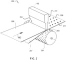
- FIG 2 is a schematic view illustrating an example of an ultrasonic bonding apparatus 200, which may benefit from the cooling methods according to various embodiments.
- the apparatus 200 is somewhat similar to the apparatus 100 shown in Figure 1 and all or some of the details discussed with respect to Figure 1 apply to Figure 2 .
- the apparatus 200 comprises a first device 201 and a second device 102 positioned to form a nip 204 therebetween.
- the first device 201 may comprise an anvil roll comprising a plurality of nubs 203 positioned on an outer circumference.
- the second device may be identical to, or similar to, the second device 102 as described with reference to Figure 1 .
- One or more substrates such as a first substrate 206 and/or a second substrate 207 may be positioned or passed through the nip 204 in a machine direction.
- the second device 102 is positioned in close proximity to the outer surface of the rotating first device 201 and in contact with, or in close proximately with, the substrates 206, 207 being processed.
- a portion of the substrates 206, 207 in contact with the first device 201 at the nubs 203 and the second device 102 may be softened by the vibration energy from the second device 202, thereby bonding the substrates 206, 207 together to form a bonded composite 209 comprising a plurality of bonds 211.
- the second device for example, the sonotrode
- the second device is normally stationary except for vibration
- the second device is susceptible to localized heating above the melting temperature of the polymer, which may lead to burn through in substrates where the second device may actually push through the molten polymer and directly contact the anvil.
- Equipment damage and substantial product quality defects such as large tears in substrates may occur in such cases.
- This burn-through problem limits the applied energy from a second device, such as a sonotrode, which in turn limits the line rate and throughput when making substrates.
- very high line rates and throughputs are critical.
- second devices such as sonotrodes
- This localized overheating may lead to unintended melting, holes, and/or tears in the hook patch, or around the hook patch, or around bonded areas. It has further been discovered that this localized overheating may increase as line speed is increased. Frequent tears have been observed at the trailing edge of the hooks patch and sometimes tear outs of the entire patch have been observed.
- localized overheating appears to be influenced or caused by trade-offs between the fatigue life and the thermal conductivity when selecting a material or materials for construction of the second device.
- Other factors may also influence the thermal diffusivity of a particular second device, such as a particular sonotrode made from particular materials. These other factors may include but are not limited to the temperature, pressure, and composition of the surrounding air or environment, as well as the density of the sonotrode's structure. Comparisons between second devices, such as sonotrodes, comprising different materials should, therefore, be made between similar structures operating under similar environmental conditions.
- Aluminum has a much higher thermal conductivity than does titanium.
- An aluminum sonotrode would not be expected to generate a hot spot over the hook patch or around bonded areas as readily as does a titanium sonotrode. As such, the present inventors would not expect tears when using an aluminum sonotrode based on modeling data.
- a trade-off exists, however, because aluminum has a limited fatigue life, and is normally not desired for sonotrodes in the nonwoven, film, and/or absorbent article industry, or other industries, which must operate at very high throughputs to be economical. The high throughputs required may severely shorten the life of a sonotrode with inadequate fatigue resistance.
- ultrasonic bonding processes are typically used for bond patterns that are intermittent, typically at about 2% coverage.
- coverage refers to the percentage of material that is melted to form a bond between substrate layers.
- a typical bonding pattern for nonwoven materials is an 8 mm by 5 mm grid with a plurality of 0.5 mm interlayer bonds spaced throughout at a coverage of about 2% to about 5%.
- Components of absorbent articles, such as a patch comprising projections or hooks may have a much denser pattern.
- projections or hooks for an absorbent article may cover a 30mm machine direction by 20mm cross direction patch of over 96% coverage of projections and hooks.
- coverage refers to the percentage of material that is melted to form a projection or a hook. In such applications, the energy density is much higher, and it has been discovered that a hot spot may form on or proximate to the working surface of the second device.
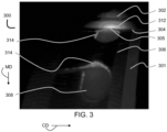
- Figure 3 is a still frame photograph from an infrared video observing an ultrasonic bonding and forming system 300 for ultrasonic forming and bonding showing a substrate 306 (e.g., a landing zone for a taped absorbent article) passing through a nip 304 formed between a first device 301 and a second device 302 operating at ambient conditions.
- the first device 301 is a cylindrical rotating anvil and the second device 302 is titanium sonotrode.
- a portion of the substrate 306 is heated and pressed against the first device 301 at a contact point 305 to fill cavities disposed at regular intervals along the outer circumference of the first device 301, thereby forming patches 308 of projections or hooks, which may be useful as a touch fastener in an absorbent article such as a diaper.
- the original photograph includes an automatically generated gradient showing differing temperatures, in which black is less than 30 degrees Celsius, white is about 90 degrees Celsius.
- the gradient from low temperature to high temperature was automatically generated.
- a localized overheating region 312 is within about 8 mm to about 10 mm of the contact point 305 between the first device 301 (e.g., the anvil) and the second device 302 (e.g., the sonotrode).
- the localized overheating region 312 is characterized by an elevated temperature within a distance of the contact point 305.
- the distance may be within about 3 mm to about 15 mm of the contact point, specifically reciting all 0.1 mm increments within the above-recited ranges and all ranges formed therein or thereby.
- the localized overheating region is characterized by an elevated temperature of about 50 degrees Celsius or even about 70 degrees Celsius or up to about 150 to about 170 degrees Celsius within about 3 mm to about 5 mm of the contact point 305.
- the localized overheating at region 312 causes excessive heating of the substate 306, especially at burn-through regions 314, which may also be referred to as tears, or holes.
- the tears, rips, holes, or burn-through regions are considered defects by consumers and are highly undesirable.
- the temperature of the localized overheating region 312 at time the burn-through regions 314 were caused was about 90 to about 120 degrees Celsius.
- the trailing edge material of the burn-through region 314 on the patch as measured on IR camera was about 100 to about 110 degrees Celsius at the time the burn-through regions 314 were caused.
- Figure 4 is a photograph showing burn-through regions 314 in the substrate 306 after passing through the nip 304 and being subjected to the localized overheating at the localized overheating region 312.
- the high-speed infrared video observations of the system 300 was the first evidence that the heating problem was one of localized heating in a small region of the sonotrode, i.e., the localized overheating region 312, about 20mm wide, rather than heating of the entire 85mm wide sonotrode.
- the localized deformation of a titanium sonotrode at the localized overheating region was investigated in detail.
- the displacement of the sonotrode was large enough that hooks were no longer formed in the substrate. This deformation is believed to be in the range of about 10 microns to about 30 microns.
- the specific titanium sonotrode observed had a characteristic length of 20mm in the cross direction. It is noted that the coefficient of thermal expansion of titanium is 4.8 ⁇ 10 -6 m/(m-K). A peak temperature rise of about 140K was observed, which resulted in about a 13 micron CD length change manifesting as bowing of the sonotrode at the contact point.
- the degree of deformation was significant because the thickness of an example nonwoven substrate before passing through the nip is typically over 100 microns; the thickness of the nonwoven substrate after passing through the nip is about 50 microns, for regions outside of any hook formation region; and the thickness of the nonwoven substrate is only about 20 microns to 50 microns, or about 25 microns to about 45 microns after passing through the nip in regions in which hooks or projections are formed, specifically reciting all 1-micron increments within the above-recited ranges and all ranges formed therein or thereby.
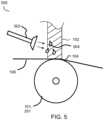
- FIG. 5 is schematic diagram illustrating an example of an unsuccessful air-cooling system 500.
- a blower 502 was mounted and directed cold air, represented by arrows, at the second device 102.
- the present inventors then improved this cooling process with a larger commercial chiller for more cooling capacity, a larger blower for more air velocity to drive the convective heat transfer coefficient, and nozzles which focused the cold air on the hot spot of the sonotrode.
- This design has worked for line speeds of only about 30 m/min to about 40 m/min, which is not acceptable in absorbent article manufacturing or in other industries.
- a complication of the cold air blast may be condensation 504 forming on the sonotrode, which drips on the web. The water may interfere with the process and causes holes or tears in the hook patch.
- Various embodiments provide cooling methods and associated devices that solve one or more of the above-mentioned problems.
- low thermal conductivity refers to materials having a thermal conductivity of less than 100, less than 50, or less than 30 W/(m-K), but greater than 5 W/m-K), specifically reciting all 1 W/(m-K) increments within the above-recited ranges and all ranges formed therein or thereby.
- low thermal conductivity materials include but are not limited to steel, steel comprising carbon, steel comprising nickel, stainless steel, titanium, and combinations, coatings, or alloys thereof.
- high thermal conductivity refers to materials having a thermal conductivity of greater than or equal to 150, or greater than or equal to 180 W/(m-K), but less than 2000 W/m-K), specifically reciting all 1 W/(m-K) increments within the above-recited ranges and all ranges formed therein or thereby.
- high thermal conductivity materials include but are not limited to diamond, sapphire, aluminum, copper, bronze, gold, silver, and combinations, coatings, or alloys thereof. Materials such as carbon-carbon composites may also be employed.
- Titanium alloys useful according to various embodiments, may exhibit thermal diffusivities in a range of from about 1 ⁇ 10 -6 to about 3 ⁇ 10 -6 m 2 /s.
- Steels useful according to various embodiments, may exhibit thermal diffusivities in a range of from about 2 ⁇ 10 -6 to about 4 ⁇ 10 -6 m 2 /s, specifically reciting all 1 ⁇ 10 -6 m 2 /s increments within the above-recited ranges and all ranges formed therein or thereby.
- Aluminum alloys useful according to various embodiments, may exhibit thermal diffusivities in a range of from about 2 ⁇ 10 -5 to about 9 ⁇ 10 -5 m 2 /s, specifically reciting all 1 ⁇ 10 -5 m 2 /s increments within the above-recited ranges and all ranges formed therein or thereby.
- Copper alloys useful according to various embodiments, may exhibit thermal diffusivities in a range of from about 5 ⁇ 10 -5 to about 1 ⁇ 10 -4 m 2 /s, specifically reciting all 1 ⁇ 10 -4 m 2 /s increments within the above-recited ranges and all ranges formed therein or thereby.
- Sonotrodes may comprise a material or only materials having a thermal diffusivity in a range of 1 ⁇ 10 -6 to about 5 ⁇ 10 -6 m 2 /s.
- Heat sinks may comprise a material or only materials having a thermal diffusivity in a range of 2 ⁇ 10 -5 to about 2 ⁇ 10 -4 m 2 /s, specifically reciting all 1 ⁇ 10 -4 m 2 /s increments within the above-recited ranges and all ranges formed therein or thereby.
- Ultrasonic bonding methods and apparatuses which require less coverage than forming methods and apparatuses may achieve line speeds of about 500 m/min to about 700 m/min, specifically reciting all 1 m/min increments within the above-recited ranges and all ranges formed therein or thereby.
- cooling techniques and apparatuses may be applied to ultrasonic bonding in general, including applications outside of the nonwoven, film, or absorbent article field.
- ultrasonic bonding of nonwovens burn-through often limits the ultrasonic force and amplitude in bonding applications, which in turn limits the energy input and line rate.
- ultrasonic bonding provides excellent bond strength, a soft aesthetic, and flexibility of pattern, but is often limited to rates slower than the 500 m/min to 700 m/min which is common in the absorbent article industry.
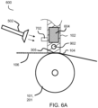
- Figure 6A is an example according to various embodiments illustrating a schematic cross-sectional diagram of a method for manufacturing portions of absorbent articles and an apparatus for altering a substrate for use in an absorbent article.
- the method and apparatus may be similar to the method and apparatus illustrated in Figure 5 , however, according to various embodiments, the second device 102 may comprise one or more projections 702 and/or one or more cavities 902.
- the cavities may extend in the machine direction and/or in the cross direction.
- a fluid, represented by arrows may be directed at the second device 102 and the one or more projections 702. Additionally or alternatively, a fluid may be conveyed through the one or more cavities 902. In either case, the fluid may help to cool the second device.
- the fluid such as air from a blower 502 may provide the same or similar degree of cooling without causing excessive condensation. Without being bound by theory, this improvement may be due, at least in part, to the increased surface area provided by the one or more projections 702, which allows a warmer fluid to provide the same degree of cooling.
- the fluid may comprise water, air, glycol, a heat transfer oil, combinations thereof, or other suitable cooling fluids.
- the second device 102 may be covered in whole or in part with insulation 604, such as a foam rubber sheet, paper, or plastic. The insulation 604 may be useful to reduce or to prevent condensation, frost, or ice from accumulating.
- the method may comprise conveying a first substrate 206 and a second substrate 207 as shown in Figure 6B through the nip 204.
- the step of transmitting vibrational energy from the second device 102 toward the first device 201 via the nip 204 to alter the substrates may comprise bonding the first substrate 206 to the second substrate 207 via a plurality of bonds 211, as already discussed with respect to Figure 2 . All other aspects of the method and the apparatus may be substantially the same.
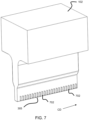
- Figures 7 and 8 are examples according to various embodiments illustrating a second device 102 having a plurality of projections 702 disposed thereon proximate to a working surface or contact point 305 of the second device 102.
- the plurality of projections 702 are vertically-aligned or extend perpendicularly to the cross direction CD.
- the plurality of projections 702 are horizontally aligned or extend in parallel to the cross direction CD.
- a combination of vertically-aligned and horizontally-aligned projections 702 is also contemplated. Also contemplated are other configurations in which the projections are not vertically or horizontally aligned but which are instead angled or even randomly distributed on the second device 102.
- various embodiments relate to a method of manufacturing portions of absorbent articles.
- the method may comprise conveying a substrate 106 through a nip 104 formed between a first device 101, 201 and a second device 102, transmitting vibrational energy from the second device 102 toward the first device 101, 201 via the nip 104 to alter the substrate 106.
- the second device 102 may be a sonotrode.
- the first device 101, 201 may be an anvil roll, such as a rotating anvil.
- the vibration energy may be ultrasonic energy.
- the step of transmitting vibrational energy from the second device toward the first device 101 via the nip 104 to alter the substrate 106 may be intermittent or continuous.
- the method may further comprise providing a plurality of recesses 107, as shown in Figure 1 in the outer surface of the first device 101.
- the recesses 107 may have a shape configured to produce projections 109 suitable for use in a touch fastener.
- the step of transmitting vibrational energy from the second device 102 toward the first device 102 via the nip 104 to alter the substrate 106 may comprise locally softening a portion of the substrate 106 to force a portion of the softened material into the recesses 107 to form projections 109 suitable for use in a touch fastener.
- the method may further comprise providing a second projection 702 extending from the second device 102 or any number of projections 702.
- the second projection 702 may be in thermal communication with the second device 102 and may be positioned proximate to a working surface or contact point 305 of the second device 102. Without being bound by theory, positioning the one or more projections near the contact point 305 may help alleviate the localized overheating previously discussed. Indeed, the method may further comprise cooling the second device 102 by transferring thermal energy from the second device 102 to the second projection 702 and conveying a chilled fluid over the second projection 702 to cool the second projection 102.
- various embodiments relate to an apparatus 600 for altering a substrate 106 for an absorbent article.
- the apparatus 600 may comprise a first device 101, 201, a second device 102 configured to transmit vibrational energy toward a nip 104 formed between the second device 102 and the first device 101, and a projection 702 extending from the second device 102.
- the projection 702 may be in thermal communication with the second device 102 and may be positioned proximate to a working surface or contact point 305 of the second device 102, where the localized heating was unexpectedly discovered, and which is illustrated in Figure 3 .
- the projection 702 may be configured to cool the working surface or contact point 305 of the second device while a substrate 106 is conveyed through the nip 104 to be altered by the vibrational energy.
- the apparatus 600 may further comprise a second projection 702 extending from the second device 102.
- the second projection 702 may be in thermal communication with the second device 102 and, as discussed with respect to the method embodiments, may be positioned proximate to a working surface or contact point 305 of the second device 102.
- the second projection 702 may be configured to cool the working surface or contact point 305 of the second device 102 while the substrate 106 is conveyed through the nip 104 to be altered by the vibrational energy.
- the projection or projections may be in thermal communication with the second device.
- two bodies in “thermal communication” are configured such that if one of the two bodies loses heat, the other body may gain at least a portion of that heat.
- the projection(s) may be integral with the second device or separable from the second device.
- the projection(s) may be joined to a portion of the second device.
- the projection(s) may comprise the same material or a different material than a primary material of the second device.
- the projection(s) may comprise a material having a high thermal conductivity as described herein or the projection(s) may comprise a material having a low thermal conductivity as described herein.
- the projection(s) may comprise a material that has a higher thermal conductivity than the primary material of the second device.
- the proj ection(s) may comprise aluminum or brass, thereby providing a higher thermal conductivity than a second device primarily comprising titanium.
- the term "primary material” refers to the material that constitutes the majority of the relevant regions of the second device 102 or to the material that most influences the overall thermal conductivity of the relevant regions of the second device 102.
- the relevant regions of the second device 102 are the regions that need to be cooled, for example, the areas of the second device 102 in which a localized overheating or deformation is to be reduced or prevented, including but not limited to the working surface or contact point 305.
- various embodiments may comprise providing one or more cavities 902, 912 in the second device 102 proximate to a working surface or contact point 305 of the second device 102.
- a fluid may be conveyed through the cavity to cool the second device 102 by transferring thermal energy from the second device 102 to the fluid.
- the fluid may comprise water, air, glycol, or any suitable heat transfer fluid or oil.
- the fluid type may be chosen to avoid cavitation.
- the fluid may be filtered to remove impurities which may cause cavitation.
- the fluid may be pressurized to prevent or minimize cavitation.
- the fluid may be chilled.
- the fluid may be chilled to -80°C to 20°C, -25°C to 20°C, -24°C to 5°C, or -16°C to +1°C, specifically reciting all 1°C increments within the specified ranges and all ranges formed therein or thereby.
- the fluid may be chilled within 5°C, or 2°C, of the localized dew point.
- the one or more cavities 902, 912 may be positioned at a location proximate to the working surface or contact point 305 of the second device 305.
- the location proximate to the working surface or contact point may be within about 0.1 mm to about 25 mm, or within about 0.5mm to about 15mm from the working surface, specifically reciting all 0.1 mm increments within the specified ranges and all ranges formed therein or thereby.
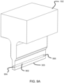
- Figure 9A is an example according to various embodiments illustrating a second device 102 having a cavity 902 through which a fluid may be conveyed to cool the second device 102.
- the cavity 902 may have a first port 904 and a second port 906.
- Figure 9B is an example according to various embodiments illustrating a second device 102 having a plurality of cavities 902, 912 through which a fluid may be conveyed to cool the second device 102.
- the plurality of cavities may comprise a first cavity 902 having a first port 904 and a second port 906 and a second cavity 912 having a third port 914 and a second port 916.
- Figure 9C is an example according to various embodiments illustrating a second device 102 having a plurality of cavities 902 oriented in a machine direction.
- a fluid may be conveyed through one or more of the plurality of cavities 902 to cool the second device 102 by transferring thermal energy from the second device 102 to the fluid.
- the plurality of cavities 902 may be disposed at a location proximate to a working surface or contact point 305 of the second device 102.
- the fluid may comprise water, air, glycol, or any suitable heat transfer fluid or oil.
- the method according to various embodiments may further comprise conveying a fluid through the cavity or cavities and cooling the second device 102 by transferring thermal energy from the second device to the fluid.
- Figure 10A is an example according to various embodiments illustrating the second device 102 shown in Figure 9A with ports attached to tubing for conveying a fluid through the cavity 902. More specifically, a first section of tubing 1004 may be attached to the first port 904, which may serve as an inlet or an outlet for the fluid. Similarly, a second section of tubing 1006 may be attached to the second port 906, which may serve as an inlet or an outlet for the fluid.
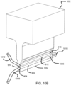
- Figure 10B is an example according to various embodiments illustrating the second device 102 shown in Figure 9B , having a first cavity 902 and a second cavity 912 with ports attached to tubing for conveying a fluid through the cavities.
- the first port 904 may be connected to a first section of tubing 1008 and may function as an inlet to the first cavity 902.
- the second port 906 may be connected to a second section of tubing 1010, which may redirect the fluid to the fourth port 916 to enter the second cavity 912.
- the third port 914 may be connected to a third section of tubing 1012 and may function as an outlet to the second cavity 912. It is to be understood that the fluid may flow in the opposite direction with the third port 914 functioning as the inlet and the first port 904 functioning as the outlet. It is to be appreciated that any number of cavities may be employed and similarly connected to convey fluid circuitously through the second device 102.
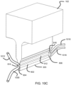
- Figure 10C is an example according to various embodiments illustrating the second device 102 shown in Figure 9B , having a first cavity 902 and a second cavity 912 with ports attached to tubing for conveying a fluid through the cavities.
- the first port 904 may be connected to a first section of tubing 1008 and may function as an inlet or as an outlet to the first cavity 902.
- the second port 906 may be connected to a second section of tubing 1016 and may function as an inlet or as an outlet to the first cavity 902.
- the third port 914 may be connected to a third section of tubing 1012 and may function as an inlet or as an outlet to the second cavity 912.
- the fourth port 916 may be connected to a fourth section of tubing 1018 and may function as an inlet or as an outlet to the second cavity 912. It is to be appreciated that any number of cavities may be employed and similarly connected to convey fluid in a plurality of directions through the second device 102. The plurality of directions may be the same or different.
- any of the substrates described herein may comprise one or more layers of one or more nonwoven materials, one or more films, combinations of different nonwoven materials, combinations of different films, combinations of one or more films and one or more nonwoven materials, or combinations of one or more different materials, for example, depending on the specific purpose for which they are intended.
- the substates may comprise spunbond, meltblown, or carded materials.
- the substrates may also comprise polyethylene films.
- the nonwoven substates may or may not be hydroentangled.
- Some substrates for nonwoven materials may comprise PE/PP bicomponent fiber spunbond substates.
- Other suitable substrates may comprise spunbond substrates comprising side-by-side crimped fibers (e.g., PE/PP or PP/PP) that are bonded via calendar (thermal point) bonding or through-air bonding.
- Other suitable substrates may comprise carded, through-air bonded or resin bonded (highloft) nonwovens comprising PE/PP or PE/PET fibers.
- the substates may comprise microfibers and/or nanofibers, optionally with other fibers. In some circumstances, multiple layer substates may be desired over a single layer substates (even at the same basis weight) due to increased uniformity/opacity and the ability to combine substates having different properties.
- the layers may have the same or different surface energy.
- Fibers of the substrates may comprise any suitable thermoplastic polymers.
- Example thermoplastic polymers are polymers that melt and then, upon cooling, crystallize or harden, but that may be re-melted upon further heating.
- Suitable thermoplastic polymers may have a melting temperature (also referred to as solidification temperature) from about 60°C to about 300°C, from about 80°C to about 250°C, or from about 100°C to about 215°C, specifically reciting all 0.5°C increments within the specified ranges and all ranges formed therein or thereby.
- the molecular weight of the thermoplastic polymer may be sufficiently high to enable entanglement between polymer molecules and yet low enough to be melt spinnable.
- thermoplastic polymers may be derived from any suitable material including renewable resources (including bio-based and recycled materials), fossil minerals and oils, and/or biodegradable materials.
- thermoplastic polymers include polyolefins, polyesters, polyamides, copolymers thereof, and combinations thereof.
- polyolefins include polyethylene or copolymers thereof, including low density, high density, linear low density, or ultra-low density polyethylenes.
- the thermoplastic polymer component may be a single polymer species or a blend of two or more thermoplastic polymers e.g., two different polypropylene resins.
- fibers of a first nonwoven layer of a substrate may comprise polymers such as polypropylene and blends of polypropylene and polyethylene
- a second nonwoven layer of the substate may comprise fibers selected from polypropylene, polypropylene/polyethylene blends, and polyethylene/polyethylene terephthalate blends.
- the second nonwoven layer may comprise fibers selected from cellulose rayon, cotton, other hydrophilic fiber materials, or combinations thereof.
- the fibers of the layer of the substrate may comprise monocomponent fibers, bi-component fibers, and/or bi-constituent fibers, round fibers or non-round fibers (e.g., capillary channel fibers), and may have major cross-sectional dimensions (e.g., diameter for round fibers) ranging from about 0.1 microns to about 500 microns.
- the fibers may also be a mixture of different fiber types, differing in such features as chemistry (e.g. polyethylene and polypropylene), components (monoand bi-), denier (micro denier and >2 denier), shape (i.e. capillary and round) and the like.
- the fibers may range from about 0.1 denier to about 100 denier.
- Example substrates are contemplated where a first plurality of fibers and/or a second plurality of fibers comprise additives in addition to their constituent chemistry.
- suitable additives include additives for coloration, antistatic properties, lubrication, softness, hydrophilicity, hydrophobicity, and the like, and combinations thereof.
- the term "monocomponent fiber(s)” refers to a fiber formed from one extruder using one or more polymers. This is not meant to exclude fibers formed from one polymer to which small amounts of additives have been added for coloration, antistatic properties, lubrication, hydrophilicity, etc.
- bi-component fiber(s) refers to fibers which have been formed from at least two different polymers extruded from separate extruders but spun together to form one fiber.
- Bi-component fibers are also sometimes referred to as conjugate fibers or multicomponent fibers.
- the polymers are arranged in substantially constantly positioned distinct zones across the cross-section of the bi-component fibers and extend continuously along the length of the bi-component fibers.
- the configuration of such a bi-component fiber may be, for example, a sheath/core arrangement where one polymer is surrounded by another or may be a side-by-side arrangement, eccentric arrangements, a pie arrangement, or an "islands-in-the-sea" arrangement.
- fibers which may be used in the first nonwoven layer include polyethylene/polypropylene side-by-side bi-component fibers.
- Another example is a polypropylene/polyethylene bi-component fiber where the polyethylene is configured as a sheath and the polypropylene is configured as a core within the sheath.
- Still another example is a polypropylene/polypropylene bi-component fiber where two different propylene polymers are configured in a side-by-side configuration.
- forms are contemplated where the fibers of a nonwoven layer are crimped.
- Bi-component fibers may comprise two different resins, e.g., a first polypropylene resin and a second polypropylene resin.
- the resins may have different melt flow rates, molecular weights, or molecular weight distributions.
- bi-constituent fiber(s) refers to fibers which have been formed from at least two polymers extruded from the same extruder as a blend. Bi-constituent fibers do not have the various polymer components arranged in relatively constantly positioned distinct zones across the cross-sectional area of the fiber and the various polymers are usually not continuous along the entire length of the fiber, instead usually forming fibrils which start and end at random. Bi-constituent fibers are sometimes also referred to as multi-constituent fibers. In other examples, a bi-component fiber may comprise multi constituent components.
- non-round fiber(s) describes fibers having a non-round cross-section and includes “shaped fibers” and “capillary channel fibers.” Such fibers may be solid or hollow, and they may be tri-lobal, delta-shaped, and may be fibers having capillary channels on their outer surfaces.
- nonwoven materials for the substates may comprise spunlace materials, needle punched materials, wet-laid materials, or air-laid materials, for example.
Landscapes
- Mechanical Engineering (AREA)
- Engineering & Computer Science (AREA)
- Chemical & Material Sciences (AREA)
- Physics & Mathematics (AREA)
- Thermal Sciences (AREA)
- Analytical Chemistry (AREA)
- Chemical Kinetics & Catalysis (AREA)
- Organic Chemistry (AREA)
- Health & Medical Sciences (AREA)
- Toxicology (AREA)
- General Health & Medical Sciences (AREA)
- Electromagnetism (AREA)
- Lining Or Joining Of Plastics Or The Like (AREA)
Abstract
Description
- This application claims the benefit of
U.S. Provisional Application No. 63/331,935, filed April 18, 2022 - The present disclosure relates generally to forming and bonding substrates via vibrational energy and more specifically relates to cooling methods and apparatuses for ultrasonic forming and bonding of substrates.
- The discussion of shortcomings and needs existing in the field prior to the present disclosure is in no way an admission that such shortcomings and needs were recognized by those skilled in the art prior to the present disclosure.
- Sources of vibration energy in combination with an anvil may be used to create bonds in substrates conveyed therebetween and/or to create surface features in substrates conveyed therebetween. Surface features may include projections or hooks, as may be useful in hook and loop fasteners.
- More specifically, sources of vibration energy in combination with an anvil may be used to create bonds in substrates conveyed therebetween. Examples of substrates bonded together by sources of vibration energy in combination with an anvil may include but are not limited to nonwoven materials and films of various types, which will be discussed in greater detail hereinafter. Bonds may be formed between nonwoven-nonwoven, film-nonwoven, or film-film. The sources of vibration energy may use ultrasonic energy. The source of vibration energy may press against the substates to melt, to soften, and/or to deform a portion of the substrates where a bond is desired. The anvil may have a bonding nub around which the substrates are melted. The bonded substrates may have many uses, including but not limited to components of absorbent articles.
- Additionally or alternatively, sources of vibration energy in combination with an anvil with a plurality of projection recesses formed therein may be used to create projections or hooks in substrates conveyed therebetween. Examples of substrates include but are not limited to films and/or nonwoven materials. These sources of vibration energy may use ultrasonic energy. To form the projections or hooks, the substrate(s) may be conveyed through a nip between a source of vibration energy and an anvil with a plurality of projection recesses defined therein. The source of vibration energy presses against the substrate to melt, to soften, and/or to deform a portion of the substate into a deformable film that may flow, stretch, and/or otherwise deform into the plurality of projection recesses. The substrate(s) may then be moved out of the nip and the substrate may be removed from the anvil, resulting in a substrate having a plurality of projections or hooks in some regions, melted substrate around the projections or hooks, and/or normal nonwoven or film in other regions (non-melted regions). The plurality of projections may form one side of a touch fastener for an absorbent article.
- Without being bound by theory, vibration energy may create a polymer flow or deformation into the projection recesses and/or against the nubs by heating a nonwoven and/or film via hysteresis losses from repeated compression and expansion of the polymer material in response to the vibration energy. A sonotrode, or ultrasound horn, may press against the polymer material with sinusoidal motion of the working surface of several tens of microns amplitude and a frequency of typically 20-40 kHz. Due primarily to high shear rates from high frequency compression, and aided by elevated temperature, the polymers exhibit shear thinning and flow more easily due to a lower apparent viscosity. The process is inherently inefficient, which may be due to impedance mismatches between the titanium or aluminum sonotrode and the low modulus polymer. Some sources suggest that only about 12% of the applied energy goes into melting the polymer. Due to the high cycle rate, sonotrodes for continuous duty nonwoven or film applications are typically titanium, which has excellent fatigue resistance, but poor thermal diffusivity.
- Unsatisfactory results, including rips, tears, and holes in bonded or formed substrates have limited the applicability of ultrasonic bonding and forming processes at the high throughputs and line speeds required in the absorbent article industry, and other industries. A need, therefore, exists for methods and devices useful for ultrasonic forming and bonding of substrates in the absorbent article industry, and other industries.
- Various embodiments solve the above-mentioned problems and provide methods and devices useful for ultrasonic forming and bonding of substrates in the absorbent article industry.
- Various embodiments relate to a method of manufacturing portions of absorbent articles comprising conveying a substrate through a nip formed between a first device and a second device, transmitting vibrational energy from the second device toward the first device via the nip to alter the substrate, providing a projection extending from the second device, cooling the second device by transferring thermal energy from the second device to the projection, and conveying a chilled fluid over the projection to cool the projection. The projection may be in thermal communication with the second device and may be positioned proximate to a working surface of the second device. In addition to providing the projection or as an alternative thereto, various embodiments relate to a method that may comprise providing a cavity in the second device proximate to a working surface of the second device, conveying a chilled fluid through the cavity. and cooling the second device by transferring thermal energy from the second device to the chilled fluid.
- Various embodiments relate to an apparatus for altering a substrate for an absorbent article, comprising a first device, a second device configured to transmit vibrational energy toward a nip formed between the second device and the first device, and a projection extending from the second device. The projection may be in thermal communication with the second device and may be positioned proximate to a working surface of the second device. The projection may be configured to cool a working surface of the second device while a substrate is conveyed through the nip to be altered by the vibrational energy. In addition to the projection or as an alternative thereto, various embodiments relate to an apparatus that may comprise a cavity in the second device proximate to a working surface of the second device. The cavity may be configured to convey a chilled fluid through the second device to cool a working surface of the second device while a substrate is conveyed through the nip to be altered by the vibrational energy.
- These and other features, aspects, and advantages of various embodiments will become better understood with reference to the following description, figures, and claims.
- Many aspects of this disclosure can be better understood with reference to the following figures.
-
Figure 1 is a schematic cross-sectional side view illustrating an example of an ultrasonic forming apparatus, which may benefit from the cooling methods according to various embodiments. -
Figure 2 is a schematic perspective view illustrating an example of an ultrasonic bonding apparatus, which may benefit from the cooling methods according to various embodiments. -
Figure 3 is a still frame photograph from an infrared video observing an ultrasonic forming system. -
Figure 4 is a photograph showing burn-through regions in the substrate fromFigure 3 after passing through the nip and being subjected to the localized overheating region. -
Figure 5 is a schematic diagram illustrating an example of an unsuccessful air-cooling system. -
Figure 6A is an example according to various embodiments illustrating a schematic cross-sectional diagram of a method for manufacturing portions of absorbent articles and an apparatus for altering a substrate for use in an absorbent article. -
Figure 6B is an example according to various embodiments illustrating a schematic perspective view of a method for manufacturing portions of absorbent articles and an apparatus for altering a substrate for use in an absorbent article. -
Figure 7 is an example according to various embodiments illustrating a second device having a plurality of vertical projections disposed thereon proximate to a working surface or contact point of the second device. -
Figure 8 is an example according to various embodiments illustrating asecond device 102 having a plurality of horizontal projections disposed thereon proximate to a working surface or contact point of the second device. -
Figure 9A is an example according to various embodiments illustrating a second device having a cavity through which a fluid may be conveyed to cool the second device. -
Figure 9B is an example according to various embodiments illustrating a second device having a plurality of cavities through which a fluid may be conveyed to cool the second device. -
Figure 9C is an example according to various embodiments illustrating a second device having a plurality of cavities oriented in a machine direction. -
Figure 10A is an example according to various embodiments illustrating the second device shown inFigure 9A with ports attached to tubing for conveying a fluid through the cavity. -
Figure 10B is an example according to various embodiments illustrating the second device shown inFigure 9B with ports attached to tubing for conveying a fluid through the cavities. -
Figure 10C is an example according to various embodiments illustrating the second device shown inFigure 9B , having a first cavity and a second cavity with ports attached to tubing for conveying a fluid through the cavities in a different configuration. - It should be understood that the various embodiments are not limited to the examples illustrated in the figures.
- This disclosure is written to describe the invention to a person having ordinary skill in the art, who will understand that this disclosure is not limited to the specific examples or embodiments described. The examples and embodiments are single instances of the invention which will make a much larger scope apparent to the person having ordinary skill in the art. Unless defined otherwise, all technical and scientific terms used herein have the same meaning as commonly understood by the person having ordinary skill in the art. It is also to be understood that the terminology used herein is for the purpose of describing examples and embodiments only, and is not intended to be limiting, since the scope of the present disclosure will be limited only by the appended claims.
- All the features disclosed in this specification (including any accompanying claims, abstract, and drawings) may be replaced by alternative features serving the same, equivalent, or similar purpose, unless expressly stated otherwise. Thus, unless expressly stated otherwise, each feature disclosed is one example only of a generic series of equivalent or similar features. The examples and embodiments described herein are for illustrative purposes only and that various modifications or changes in light thereof will be suggested to the person having ordinary skill in the art and are to be included within the spirit and purview of this application. Many variations and modifications may be made to the embodiments of the disclosure without departing substantially from the spirit and principles of the disclosure. All such modifications and variations are intended to be included herein within the scope of this disclosure. For example, unless otherwise indicated, the present disclosure is not limited to particular materials, reagents, reaction materials, manufacturing processes, or the like, as such can vary. It is also to be understood that the terminology used herein is for purposes of describing particular embodiments only and is not intended to be limiting. It is also possible in the present disclosure that steps can be executed in different sequence where this is logically possible.
- In everyday usage, indefinite articles (like "a" or "an") precede countable nouns and noncountable nouns almost never take indefinite articles. It must be noted, therefore, that, as used in this specification and in the claims that follow, the singular forms "a," "an," and "the" include plural referents unless the context clearly dictates otherwise. Thus, for example, reference to "a support" includes a plurality of supports. Particularly when a single countable noun is listed as an element in a claim, this specification will generally use a phrase such as "a single." For example, "a single support."
- In this specification and in the claims that follow, reference will be made to a number of terms that shall be defined to have the following meanings unless a contrary intention is apparent.
- "Standard temperature and pressure" is used herein to generally refer to 25°C and 1 atmosphere. Standard temperature and pressure may also be referred to as "ambient conditions." Unless indicated otherwise, parts are by weight, temperature is in °C, and pressure is at or near atmospheric. The terms "elevated temperatures" or "high temperatures" generally refer to temperatures of at least 100°C.
- "Disposed on" is used herein to refer to a positional state indicating that one object or material is arranged in a position adjacent to the position of another object or material. The term does not require or exclude the presence of intervening objects, materials, or layers.
- "Anvil roll" is used herein to refer to any industrial tool comprising an essentially cylindrical form having a pattern or profile on the outer circumferential surface. An anvil roll is on example of a "first device" according to various embodiments. The first device need not be but may be essentially cylindrical. A first device may be any desirable shape, including but not limited to concave, convex, or flat according to various embodiments.
- "Absorbent article" is used herein to refer to consumer products whose primary function is to absorb and retain soils and wastes. "Diaper" is used herein to refer to an absorbent article generally worn by infants, children, and incontinent persons about the lower torso. "Diaper" may include taped diapers and pant-type diapers. The term "disposable" is used herein to describe absorbent articles which generally are not intended to be laundered or otherwise restored or reused as an absorbent article (e.g., they are intended to be discarded after a single use and may also be configured to be recycled, composted, or otherwise disposed of in an environmentally compatible manner).
- "Elastic," "elastomer" or "elastomeric" are used herein to refer to materials exhibiting elastic properties, which include any material that upon application of a force to its relaxed, initial length can stretch or elongate to an elongated length more than 10% greater than its initial length and will substantially recover back to about its initial length upon release of the applied force.
- "Joined" is used herein to encompass configurations whereby an element is directly secured to another element by affixing the element directly to the other element, and configurations whereby an element is indirectly secured to another element by affixing the element to intermediate member(s) which in turn are affixed to the other element.
- "Substrate" is used herein to describe a material which is primarily two-dimensional (i.e., in an XY plane) and whose thickness (in a Z direction) is relatively small (i.e. 1/10 or less) in comparison to its length (in an X direction) and width (in a Y direction). Non-limiting examples of substrates include a web, layer or layers or fibrous materials, nonwovens, films, and foils such as polymeric films or metallic foils. These materials may be used alone or may comprise two or more layers laminated together. As such, a web is a substrate.
- "Nonwoven" is used herein to refer to a material made from continuous (long) filaments (fibers) and/or discontinuous (short) filaments (fibers) by processes such as spunbonding, meltblowing, carding, and the like. Nonwovens do not have a woven or knitted filament pattern.
- "Machine direction" (MD) is used herein to refer to the direction of material flow through a process. In addition, relative placement and movement of material can be described as flowing in the machine direction through a process from upstream in the process to downstream in the process.
- "Cross direction" (CD) is used herein to refer to a direction that is generally perpendicular to the machine direction.
- "Thermal conductivity" is used herein to refer to the quantity of heat transmitted due to a unit temperature gradient, in unit time under steady conditions in a direction normal to a surface of the unit area.
- "Thermal diffusivity" is used herein to refer to the rate of transfer of heat of a material from the hot side to the cold side - a measure of how quickly a material can absorb heat from its surroundings. It can be calculated by taking the thermal conductivity divided by density and specific heat capacity at constant pressure.
- Where a range of values is provided, it is understood that each intervening value, to the tenth of the unit of the lower limit (unless the context clearly dictates otherwise), between the upper and lower limit of that range, and any other stated or intervening value in that stated range, is encompassed within the disclosure. The upper and lower limits of these smaller ranges may independently be included in the smaller ranges and are also encompassed within the disclosure, subject to any specifically excluded limit in the stated range. Where the stated range includes one or both of the limits, ranges excluding either or both of those included limits are also included in the disclosure.
-
Figure 1 is a schematic cross-sectional side view illustrating an example of an ultrasonic forming apparatus, which may benefit from the cooling methods according to various embodiments. As shown inFigure 1 , theapparatus 100 may include afirst device 101 and asecond device 102 with a nip 104 formed therebetween. Thefirst device 101 may be an anvil roll comprising multiple hook-shaped or otherwise shapedcavities 107, along an outer periphery thereof. Thesecond device 102 may be a source of vibrational energy, such as a sonotrode or a vibrating ultrasonic horn. - A
substrate 106 may be positioned or passed through thenip 104. Thesubstrate 106 may be, but need not be limited to, a film, sheet, web, nonwoven, composite, laminate, or other form, or may be portions of a film, sheet, web, nonwoven, laminate or substrate thermoplastic material, portions of which may be used as a component of a touch fastener, for instance on a absorbent article. In their use on absorbent article, touch fasteners may be attached to a "side tab" or "ear" that the consumer uses to secure the absorbent article the wearer. These tabs may be constructed with a piece of extensible material to allow the side tab to stretch and flex when attached or when the wearer moves. The touch fasteners may also be used in a two-point fastening system on an absorbent article, where the component is positioned on a landing zone or outer cover of the absorbent article. The present disclosure further contemplates the use of pre-formed film, sheet, web, composite, laminate, etc. as a substrate material. - During operation, the
second device 102 is positioned in close proximity to an outer surface of the rotatingfirst device 101 and in contact with thesubstrate 106 being processed. Thefirst device 101 may also be a flat plate in other forms with the substate moving over the flat plate. Thesecond device 102 may be vibrated at frequencies between about 50 Hz to about 50 kHz, as required. A portion of thesubstrate 106 in contact with, or in proximity with, thefirst device 101 andsecond device 102 may be softened by the vibration energy from thesecond device 102 and a desired portion of the substrate may enter into thecavities 107 of the first device to be shaped intoprojections 109 on the front surface of the film orsheet 111 as thefirst device 101 rotates in the direction indicated inFigure 1 by the arrows. This process may be referred to as rotary forming. Force may be exerted on thesubstrate 106 as it passes through thenip 104 to apply a requisite amount of pressure to the softenedsubstrate 106 to assist its entry and filling of at least some of, or all of, thecavities 107. One example of the process is described inU.S. Pat. No. 8,784,722 . -
Figure 2 is a schematic view illustrating an example of anultrasonic bonding apparatus 200, which may benefit from the cooling methods according to various embodiments. Theapparatus 200 is somewhat similar to theapparatus 100 shown inFigure 1 and all or some of the details discussed with respect toFigure 1 apply toFigure 2 . Theapparatus 200 comprises afirst device 201 and asecond device 102 positioned to form a nip 204 therebetween. Thefirst device 201 may comprise an anvil roll comprising a plurality ofnubs 203 positioned on an outer circumference. The second device may be identical to, or similar to, thesecond device 102 as described with reference toFigure 1 . One or more substrates, such as afirst substrate 206 and/or asecond substrate 207 may be positioned or passed through thenip 204 in a machine direction. During operation, thesecond device 102 is positioned in close proximity to the outer surface of the rotatingfirst device 201 and in contact with, or in close proximately with, thesubstrates substrates first device 201 at thenubs 203 and thesecond device 102 may be softened by the vibration energy from the second device 202, thereby bonding thesubstrates composite 209 comprising a plurality ofbonds 211. - A serious need has been unexpectedly discovered for cooling methods and devices useful for ultrasonic forming and bonding of substrates. In this context, it has been discovered that the second device (for example, the sonotrode), which is normally stationary except for vibration, is susceptible to localized heating above the melting temperature of the polymer, which may lead to burn through in substrates where the second device may actually push through the molten polymer and directly contact the anvil. Equipment damage and substantial product quality defects such as large tears in substrates may occur in such cases. This burn-through problem limits the applied energy from a second device, such as a sonotrode, which in turn limits the line rate and throughput when making substrates. To process absorbent articles, and other goods, economically, very high line rates and throughputs are critical.
- More specifically, it has been unexpectedly discovered that second devices, such as sonotrodes, may overheat in a small region adjacent to the projection or hook patch or bonded area. This localized overheating may lead to unintended melting, holes, and/or tears in the hook patch, or around the hook patch, or around bonded areas. It has further been discovered that this localized overheating may increase as line speed is increased. Frequent tears have been observed at the trailing edge of the hooks patch and sometimes tear outs of the entire patch have been observed.
- Without being bound by theory, localized overheating appears to be influenced or caused by trade-offs between the fatigue life and the thermal conductivity when selecting a material or materials for construction of the second device. Other factors may also influence the thermal diffusivity of a particular second device, such as a particular sonotrode made from particular materials. These other factors may include but are not limited to the temperature, pressure, and composition of the surrounding air or environment, as well as the density of the sonotrode's structure. Comparisons between second devices, such as sonotrodes, comprising different materials should, therefore, be made between similar structures operating under similar environmental conditions.
- Aluminum has a much higher thermal conductivity than does titanium. An aluminum sonotrode would not be expected to generate a hot spot over the hook patch or around bonded areas as readily as does a titanium sonotrode. As such, the present inventors would not expect tears when using an aluminum sonotrode based on modeling data. A trade-off exists, however, because aluminum has a limited fatigue life, and is normally not desired for sonotrodes in the nonwoven, film, and/or absorbent article industry, or other industries, which must operate at very high throughputs to be economical. The high throughputs required may severely shorten the life of a sonotrode with inadequate fatigue resistance.
- In contrast to the hook/projection forming industry, most ultrasonic bonding processes on nonwovens, do not typically have this overheating problem until they are performed at high rates of speed. Ultrasonic bonding processes are typically used for bond patterns that are intermittent, typically at about 2% coverage. As used in this context, "coverage" refers to the percentage of material that is melted to form a bond between substrate layers. A typical bonding pattern for nonwoven materials is an 8 mm by 5 mm grid with a plurality of 0.5 mm interlayer bonds spaced throughout at a coverage of about 2% to about 5%. Components of absorbent articles, such as a patch comprising projections or hooks may have a much denser pattern. For example, projections or hooks for an absorbent article may cover a 30mm machine direction by 20mm cross direction patch of over 96% coverage of projections and hooks. As used in this context, "coverage" refers to the percentage of material that is melted to form a projection or a hook. In such applications, the energy density is much higher, and it has been discovered that a hot spot may form on or proximate to the working surface of the second device.
-
Figure 3 is a still frame photograph from an infrared video observing an ultrasonic bonding and formingsystem 300 for ultrasonic forming and bonding showing a substrate 306 (e.g., a landing zone for a taped absorbent article) passing through a nip 304 formed between afirst device 301 and asecond device 302 operating at ambient conditions. In the embodiment shown inFigure 3 , thefirst device 301 is a cylindrical rotating anvil and thesecond device 302 is titanium sonotrode. As thesubstrate 306 passes through thenip 304 in the machine direction a portion of thesubstrate 306 is heated and pressed against thefirst device 301 at acontact point 305 to fill cavities disposed at regular intervals along the outer circumference of thefirst device 301, thereby formingpatches 308 of projections or hooks, which may be useful as a touch fastener in an absorbent article such as a diaper. - Still referring to
Figure 3 , the original photograph includes an automatically generated gradient showing differing temperatures, in which black is less than 30 degrees Celsius, white is about 90 degrees Celsius. The gradient from low temperature to high temperature was automatically generated. Alocalized overheating region 312 is within about 8 mm to about 10 mm of thecontact point 305 between the first device 301 (e.g., the anvil) and the second device 302 (e.g., the sonotrode). Thelocalized overheating region 312 is characterized by an elevated temperature within a distance of thecontact point 305. The elevated temperature of about 50 degrees Celsius or even about 70 degrees Celsius or up to about 150 to about 170 degrees Celsius, about 90 degrees Celsius to about 120 degrees Celsius, or about 100 degrees Celsius to about 110 degrees Celsius, specifically reciting all 1-degree Celsius increments within the above-recited ranges and all ranges formed therein or thereby. The distance may be within about 3 mm to about 15 mm of the contact point, specifically reciting all 0.1 mm increments within the above-recited ranges and all ranges formed therein or thereby. In other words, the localized overheating region is characterized by an elevated temperature of about 50 degrees Celsius or even about 70 degrees Celsius or up to about 150 to about 170 degrees Celsius within about 3 mm to about 5 mm of thecontact point 305. - The localized overheating at
region 312 causes excessive heating of thesubstate 306, especially at burn-throughregions 314, which may also be referred to as tears, or holes. The tears, rips, holes, or burn-through regions are considered defects by consumers and are highly undesirable. In the specific example shown inFigure 3 , it was observed that the temperature of the localizedoverheating region 312 at time the burn-throughregions 314 were caused was about 90 to about 120 degrees Celsius. The trailing edge material of the burn-throughregion 314 on the patch as measured on IR camera was about 100 to about 110 degrees Celsius at the time the burn-throughregions 314 were caused. -
Figure 4 is a photograph showing burn-throughregions 314 in thesubstrate 306 after passing through thenip 304 and being subjected to the localized overheating at thelocalized overheating region 312. The high-speed infrared video observations of thesystem 300 was the first evidence that the heating problem was one of localized heating in a small region of the sonotrode, i.e., the localizedoverheating region 312, about 20mm wide, rather than heating of the entire 85mm wide sonotrode. - It was further discovered that the localized heating of the second device also caused localized thermal deformation of the
second device 302, which caused uneven and poor hook or projection formation. This poor quality was another major limiter of line speed. - The localized deformation of a titanium sonotrode at the localized overheating region was investigated in detail. The displacement of the sonotrode was large enough that hooks were no longer formed in the substrate. This deformation is believed to be in the range of about 10 microns to about 30 microns.
- The specific titanium sonotrode observed had a characteristic length of 20mm in the cross direction. It is noted that the coefficient of thermal expansion of titanium is 4.8×10⁻⁶ m/(m-K). A peak temperature rise of about 140K was observed, which resulted in about a 13 micron CD length change manifesting as bowing of the sonotrode at the contact point. The degree of deformation was significant because the thickness of an example nonwoven substrate before passing through the nip is typically over 100 microns; the thickness of the nonwoven substrate after passing through the nip is about 50 microns, for regions outside of any hook formation region; and the thickness of the nonwoven substrate is only about 20 microns to 50 microns, or about 25 microns to about 45 microns after passing through the nip in regions in which hooks or projections are formed, specifically reciting all 1-micron increments within the above-recited ranges and all ranges formed therein or thereby.
- The hot spot was attempted to be addresses using cold air blasts from a blower to generate an air flow, piping (for cold air), and air blast hoods mounted adjacent the sonotrode.
Figure 5 is schematic diagram illustrating an example of an unsuccessful air-coolingsystem 500. As illustrated ablower 502 was mounted and directed cold air, represented by arrows, at thesecond device 102. The present inventors then improved this cooling process with a larger commercial chiller for more cooling capacity, a larger blower for more air velocity to drive the convective heat transfer coefficient, and nozzles which focused the cold air on the hot spot of the sonotrode. This design has worked for line speeds of only about 30 m/min to about 40 m/min, which is not acceptable in absorbent article manufacturing or in other industries. A complication of the cold air blast may be condensation 504 forming on the sonotrode, which drips on the web. The water may interfere with the process and causes holes or tears in the hook patch. - Even after these attempts, a need remained for cooling methods and devices useful for ultrasonic forming and bonding of substrates.
- Various embodiments provide cooling methods and associated devices that solve one or more of the above-mentioned problems.
- Various embodiments described herein provide cooling methods that allow for the use of sonotrodes comprising a material having a low thermal conductivity. As used herein, "low thermal conductivity" refers to materials having a thermal conductivity of less than 100, less than 50, or less than 30 W/(m-K), but greater than 5 W/m-K), specifically reciting all 1 W/(m-K) increments within the above-recited ranges and all ranges formed therein or thereby. Some examples of low thermal conductivity materials that may be employed include but are not limited to steel, steel comprising carbon, steel comprising nickel, stainless steel, titanium, and combinations, coatings, or alloys thereof.
- Of course, a material having a high thermal conductivity may also be employed, according to any embodiment described herein. As used herein, "high thermal conductivity" refers to materials having a thermal conductivity of greater than or equal to 150, or greater than or equal to 180 W/(m-K), but less than 2000 W/m-K), specifically reciting all 1 W/(m-K) increments within the above-recited ranges and all ranges formed therein or thereby. Some examples high thermal conductivity materials that may be employed include but are not limited to diamond, sapphire, aluminum, copper, bronze, gold, silver, and combinations, coatings, or alloys thereof. Materials such as carbon-carbon composites may also be employed.
- Alloying of various materials may, of course, result in a wide range of material densities, which results in different thermal diffusivities. Titanium alloys, useful according to various embodiments, may exhibit thermal diffusivities in a range of from about 1×10⁻⁶ to about 3×10⁻⁶ m2/s. Steels, useful according to various embodiments, may exhibit thermal diffusivities in a range of from about 2×10⁻⁶ to about 4×10⁻⁶ m2/s, specifically reciting all 1×10⁻⁶ m2/s increments within the above-recited ranges and all ranges formed therein or thereby. Aluminum alloys, useful according to various embodiments, may exhibit thermal diffusivities in a range of from about 2×10⁻⁵ to about 9×10⁻⁵ m2/s, specifically reciting all 1×10⁻⁵ m2/s increments within the above-recited ranges and all ranges formed therein or thereby. Copper alloys, useful according to various embodiments, may exhibit thermal diffusivities in a range of from about 5×10⁻⁵ to about 1×10⁻⁴ m2/s, specifically reciting all 1×10⁻⁴ m2/s increments within the above-recited ranges and all ranges formed therein or thereby. Sonotrodes according to various embodiments may comprise a material or only materials having a thermal diffusivity in a range of 1×10⁻⁶ to about 5×10⁻⁶ m2/s. Heat sinks according to various embodiments may comprise a material or only materials having a thermal diffusivity in a range of 2×10⁻⁵ to about 2×10⁻⁴ m2/s, specifically reciting all 1×10⁻⁴ m2/s increments within the above-recited ranges and all ranges formed therein or thereby.
- Upon employing the cooling methods of various embodiments of the present disclosure, a coverage of over 70%, over 75%, over 80%, over 85%, over 90%, over 95%, over 96%, over 97%, over 98%, or over 99%, but less than 100%, specifically reciting all 0.1% increments within the above-recited ranges and all ranges formed therein or thereby, is possible without causing tears, rips, or holes in a substrate. These coverages are possible even at line speeds of about 10 m/min to about 70 m/min, about 10 m/min to about 150 m/min, about 10 m/min to about 400, m/min, about 100 m/min, or about 300 m/min to about 400 m/min, specifically reciting all 1 m/min increments within the above-recited ranges and all ranges formed therein or thereby for ultrasonic forming methods and apparatuses. These coverages and line speeds are possible even when using sonotrodes comprising a material having a high thermal conductivity or a low thermal conductivity as defined herein, including combinations and alloys thereof. Ultrasonic bonding methods and apparatuses, which require less coverage than forming methods and apparatuses may achieve line speeds of about 500 m/min to about 700 m/min, specifically reciting all 1 m/min increments within the above-recited ranges and all ranges formed therein or thereby.
- It is to be appreciated that the cooling techniques and apparatuses according to various embodiments may be applied to ultrasonic bonding in general, including applications outside of the nonwoven, film, or absorbent article field. For ultrasonic bonding of nonwovens, burn-through often limits the ultrasonic force and amplitude in bonding applications, which in turn limits the energy input and line rate. Historically, ultrasonic bonding provides excellent bond strength, a soft aesthetic, and flexibility of pattern, but is often limited to rates slower than the 500 m/min to 700 m/min which is common in the absorbent article industry.
-
Figure 6A is an example according to various embodiments illustrating a schematic cross-sectional diagram of a method for manufacturing portions of absorbent articles and an apparatus for altering a substrate for use in an absorbent article. The method and apparatus may be similar to the method and apparatus illustrated inFigure 5 , however, according to various embodiments, thesecond device 102 may comprise one ormore projections 702 and/or one ormore cavities 902. The cavities may extend in the machine direction and/or in the cross direction. A fluid, represented by arrows may be directed at thesecond device 102 and the one ormore projections 702. Additionally or alternatively, a fluid may be conveyed through the one ormore cavities 902. In either case, the fluid may help to cool the second device. In comparison to the system illustrated inFigure 5 , the fluid, such as air from ablower 502, may provide the same or similar degree of cooling without causing excessive condensation. Without being bound by theory, this improvement may be due, at least in part, to the increased surface area provided by the one ormore projections 702, which allows a warmer fluid to provide the same degree of cooling. The fluid, according to any of these embodiments, may comprise water, air, glycol, a heat transfer oil, combinations thereof, or other suitable cooling fluids. Thesecond device 102 may be covered in whole or in part withinsulation 604, such as a foam rubber sheet, paper, or plastic. Theinsulation 604 may be useful to reduce or to prevent condensation, frost, or ice from accumulating. - Additionally or alternatively, the method may comprise conveying a
first substrate 206 and asecond substrate 207 as shown inFigure 6B through thenip 204. In which case, the step of transmitting vibrational energy from thesecond device 102 toward thefirst device 201 via thenip 204 to alter the substrates may comprise bonding thefirst substrate 206 to thesecond substrate 207 via a plurality ofbonds 211, as already discussed with respect toFigure 2 . All other aspects of the method and the apparatus may be substantially the same. -
Figures 7 and8 are examples according to various embodiments illustrating asecond device 102 having a plurality ofprojections 702 disposed thereon proximate to a working surface orcontact point 305 of thesecond device 102. InFigure 7 , the plurality ofprojections 702 are vertically-aligned or extend perpendicularly to the cross direction CD. InFigure 8 , the plurality ofprojections 702 are horizontally aligned or extend in parallel to the cross direction CD. A combination of vertically-aligned and horizontally-alignedprojections 702 is also contemplated. Also contemplated are other configurations in which the projections are not vertically or horizontally aligned but which are instead angled or even randomly distributed on thesecond device 102. - With reference to
Figures 6A ,6B ,7 , and8 , various embodiments relate to a method of manufacturing portions of absorbent articles. The method may comprise conveying asubstrate 106 through a nip 104 formed between afirst device second device 102, transmitting vibrational energy from thesecond device 102 toward thefirst device nip 104 to alter thesubstrate 106. Thesecond device 102 may be a sonotrode. Thefirst device first device 101 via thenip 104 to alter thesubstrate 106 may be intermittent or continuous. The method may further comprise providing a plurality ofrecesses 107, as shown inFigure 1 in the outer surface of thefirst device 101. Therecesses 107 may have a shape configured to produceprojections 109 suitable for use in a touch fastener. The step of transmitting vibrational energy from thesecond device 102 toward thefirst device 102 via thenip 104 to alter thesubstrate 106 may comprise locally softening a portion of thesubstrate 106 to force a portion of the softened material into therecesses 107 to formprojections 109 suitable for use in a touch fastener. It is to be appreciated that the method may further comprise providing asecond projection 702 extending from thesecond device 102 or any number ofprojections 702. Thesecond projection 702 may be in thermal communication with thesecond device 102 and may be positioned proximate to a working surface orcontact point 305 of thesecond device 102. Without being bound by theory, positioning the one or more projections near thecontact point 305 may help alleviate the localized overheating previously discussed. Indeed, the method may further comprise cooling thesecond device 102 by transferring thermal energy from thesecond device 102 to thesecond projection 702 and conveying a chilled fluid over thesecond projection 702 to cool thesecond projection 102. - Similarly, various embodiments relate to an
apparatus 600 for altering asubstrate 106 for an absorbent article. Theapparatus 600 may comprise afirst device second device 102 configured to transmit vibrational energy toward a nip 104 formed between thesecond device 102 and thefirst device 101, and aprojection 702 extending from thesecond device 102. Theprojection 702 may be in thermal communication with thesecond device 102 and may be positioned proximate to a working surface orcontact point 305 of thesecond device 102, where the localized heating was unexpectedly discovered, and which is illustrated inFigure 3 . Indeed, theprojection 702 may be configured to cool the working surface orcontact point 305 of the second device while asubstrate 106 is conveyed through thenip 104 to be altered by the vibrational energy. Theapparatus 600 may further comprise asecond projection 702 extending from thesecond device 102. Thesecond projection 702 may be in thermal communication with thesecond device 102 and, as discussed with respect to the method embodiments, may be positioned proximate to a working surface orcontact point 305 of thesecond device 102. Thesecond projection 702 may be configured to cool the working surface orcontact point 305 of thesecond device 102 while thesubstrate 106 is conveyed through thenip 104 to be altered by the vibrational energy. - The projection or projections, according to various embodiments, may be in thermal communication with the second device. As used herein, two bodies in "thermal communication" are configured such that if one of the two bodies loses heat, the other body may gain at least a portion of that heat.
- The projection(s) may be integral with the second device or separable from the second device. For example, the projection(s) may be joined to a portion of the second device. The projection(s) may comprise the same material or a different material than a primary material of the second device. The projection(s) may comprise a material having a high thermal conductivity as described herein or the projection(s) may comprise a material having a low thermal conductivity as described herein. According to various embodiments, the projection(s) may comprise a material that has a higher thermal conductivity than the primary material of the second device. For example, the proj ection(s) may comprise aluminum or brass, thereby providing a higher thermal conductivity than a second device primarily comprising titanium. In this context the term "primary material" refers to the material that constitutes the majority of the relevant regions of the
second device 102 or to the material that most influences the overall thermal conductivity of the relevant regions of thesecond device 102. The relevant regions of thesecond device 102 are the regions that need to be cooled, for example, the areas of thesecond device 102 in which a localized overheating or deformation is to be reduced or prevented, including but not limited to the working surface orcontact point 305. - With reference to
Figures 6A ,6B ,9A ,9B ,9C ,10A ,10B , and10C , in addition to or as an alternative to providing one ormore projections 702, various embodiments may comprise providing one ormore cavities second device 102 proximate to a working surface orcontact point 305 of thesecond device 102. A fluid may be conveyed through the cavity to cool thesecond device 102 by transferring thermal energy from thesecond device 102 to the fluid. The fluid may comprise water, air, glycol, or any suitable heat transfer fluid or oil. The fluid type may be chosen to avoid cavitation. The fluid may be filtered to remove impurities which may cause cavitation. The fluid may be pressurized to prevent or minimize cavitation. The fluid may be chilled. The fluid may be chilled to -80°C to 20°C, -25°C to 20°C, -24°C to 5°C, or -16°C to +1°C, specifically reciting all 1°C increments within the specified ranges and all ranges formed therein or thereby. The fluid may be chilled within 5°C, or 2°C, of the localized dew point. The one ormore cavities contact point 305 of thesecond device 305. The location proximate to the working surface or contact point may be within about 0.1 mm to about 25 mm, or within about 0.5mm to about 15mm from the working surface, specifically reciting all 0.1 mm increments within the specified ranges and all ranges formed therein or thereby. -
Figure 9A is an example according to various embodiments illustrating asecond device 102 having acavity 902 through which a fluid may be conveyed to cool thesecond device 102. Thecavity 902 may have afirst port 904 and asecond port 906. -
Figure 9B is an example according to various embodiments illustrating asecond device 102 having a plurality ofcavities second device 102. The plurality of cavities may comprise afirst cavity 902 having afirst port 904 and asecond port 906 and asecond cavity 912 having athird port 914 and asecond port 916. -
Figure 9C is an example according to various embodiments illustrating asecond device 102 having a plurality ofcavities 902 oriented in a machine direction. A fluid may be conveyed through one or more of the plurality ofcavities 902 to cool thesecond device 102 by transferring thermal energy from thesecond device 102 to the fluid. The plurality ofcavities 902 may be disposed at a location proximate to a working surface orcontact point 305 of thesecond device 102. The fluid may comprise water, air, glycol, or any suitable heat transfer fluid or oil. - The method according to various embodiments may further comprise conveying a fluid through the cavity or cavities and cooling the
second device 102 by transferring thermal energy from the second device to the fluid.Figure 10A is an example according to various embodiments illustrating thesecond device 102 shown inFigure 9A with ports attached to tubing for conveying a fluid through thecavity 902. More specifically, a first section oftubing 1004 may be attached to thefirst port 904, which may serve as an inlet or an outlet for the fluid. Similarly, a second section oftubing 1006 may be attached to thesecond port 906, which may serve as an inlet or an outlet for the fluid. -
Figure 10B is an example according to various embodiments illustrating thesecond device 102 shown inFigure 9B , having afirst cavity 902 and asecond cavity 912 with ports attached to tubing for conveying a fluid through the cavities. More specifically, thefirst port 904 may be connected to a first section oftubing 1008 and may function as an inlet to thefirst cavity 902. Thesecond port 906 may be connected to a second section oftubing 1010, which may redirect the fluid to thefourth port 916 to enter thesecond cavity 912. Thethird port 914 may be connected to a third section oftubing 1012 and may function as an outlet to thesecond cavity 912. It is to be understood that the fluid may flow in the opposite direction with thethird port 914 functioning as the inlet and thefirst port 904 functioning as the outlet. It is to be appreciated that any number of cavities may be employed and similarly connected to convey fluid circuitously through thesecond device 102. -
Figure 10C is an example according to various embodiments illustrating thesecond device 102 shown inFigure 9B , having afirst cavity 902 and asecond cavity 912 with ports attached to tubing for conveying a fluid through the cavities. More specifically, thefirst port 904 may be connected to a first section oftubing 1008 and may function as an inlet or as an outlet to thefirst cavity 902. Thesecond port 906 may be connected to a second section oftubing 1016 and may function as an inlet or as an outlet to thefirst cavity 902. Thethird port 914 may be connected to a third section oftubing 1012 and may function as an inlet or as an outlet to thesecond cavity 912. Thefourth port 916 may be connected to a fourth section oftubing 1018 and may function as an inlet or as an outlet to thesecond cavity 912. It is to be appreciated that any number of cavities may be employed and similarly connected to convey fluid in a plurality of directions through thesecond device 102. The plurality of directions may be the same or different. - Any of the substrates described herein may comprise one or more layers of one or more nonwoven materials, one or more films, combinations of different nonwoven materials, combinations of different films, combinations of one or more films and one or more nonwoven materials, or combinations of one or more different materials, for example, depending on the specific purpose for which they are intended. The substates may comprise spunbond, meltblown, or carded materials. The substrates may also comprise polyethylene films. The nonwoven substates may or may not be hydroentangled.
- Some substrates for nonwoven materials may comprise PE/PP bicomponent fiber spunbond substates. Other suitable substrates may comprise spunbond substrates comprising side-by-side crimped fibers (e.g., PE/PP or PP/PP) that are bonded via calendar (thermal point) bonding or through-air bonding. Other suitable substrates may comprise carded, through-air bonded or resin bonded (highloft) nonwovens comprising PE/PP or PE/PET fibers. The substates may comprise microfibers and/or nanofibers, optionally with other fibers. In some circumstances, multiple layer substates may be desired over a single layer substates (even at the same basis weight) due to increased uniformity/opacity and the ability to combine substates having different properties. The layers may have the same or different surface energy.
- Fibers of the substrates may comprise any suitable thermoplastic polymers. Example thermoplastic polymers are polymers that melt and then, upon cooling, crystallize or harden, but that may be re-melted upon further heating. Suitable thermoplastic polymers may have a melting temperature (also referred to as solidification temperature) from about 60°C to about 300°C, from about 80°C to about 250°C, or from about 100°C to about 215°C, specifically reciting all 0.5°C increments within the specified ranges and all ranges formed therein or thereby. And, the molecular weight of the thermoplastic polymer may be sufficiently high to enable entanglement between polymer molecules and yet low enough to be melt spinnable.
- The thermoplastic polymers may be derived from any suitable material including renewable resources (including bio-based and recycled materials), fossil minerals and oils, and/or biodegradable materials. Some suitable examples of thermoplastic polymers include polyolefins, polyesters, polyamides, copolymers thereof, and combinations thereof. Some example polyolefins include polyethylene or copolymers thereof, including low density, high density, linear low density, or ultra-low density polyethylenes.
- The thermoplastic polymer component may be a single polymer species or a blend of two or more thermoplastic polymers e.g., two different polypropylene resins. As an example, fibers of a first nonwoven layer of a substrate may comprise polymers such as polypropylene and blends of polypropylene and polyethylene, while a second nonwoven layer of the substate may comprise fibers selected from polypropylene, polypropylene/polyethylene blends, and polyethylene/polyethylene terephthalate blends. In some forms, the second nonwoven layer may comprise fibers selected from cellulose rayon, cotton, other hydrophilic fiber materials, or combinations thereof.
- The fibers of the layer of the substrate may comprise monocomponent fibers, bi-component fibers, and/or bi-constituent fibers, round fibers or non-round fibers (e.g., capillary channel fibers), and may have major cross-sectional dimensions (e.g., diameter for round fibers) ranging from about 0.1 microns to about 500 microns. The fibers may also be a mixture of different fiber types, differing in such features as chemistry (e.g. polyethylene and polypropylene), components (monoand bi-), denier (micro denier and >2 denier), shape (i.e. capillary and round) and the like. The fibers may range from about 0.1 denier to about 100 denier.
- Example substrates are contemplated where a first plurality of fibers and/or a second plurality of fibers comprise additives in addition to their constituent chemistry. For example, suitable additives include additives for coloration, antistatic properties, lubrication, softness, hydrophilicity, hydrophobicity, and the like, and combinations thereof.
- As used herein, the term "monocomponent fiber(s)" refers to a fiber formed from one extruder using one or more polymers. This is not meant to exclude fibers formed from one polymer to which small amounts of additives have been added for coloration, antistatic properties, lubrication, hydrophilicity, etc.
- As used herein, the term "bi-component fiber(s)" refers to fibers which have been formed from at least two different polymers extruded from separate extruders but spun together to form one fiber. Bi-component fibers are also sometimes referred to as conjugate fibers or multicomponent fibers. The polymers are arranged in substantially constantly positioned distinct zones across the cross-section of the bi-component fibers and extend continuously along the length of the bi-component fibers. The configuration of such a bi-component fiber may be, for example, a sheath/core arrangement where one polymer is surrounded by another or may be a side-by-side arrangement, eccentric arrangements, a pie arrangement, or an "islands-in-the-sea" arrangement. Some specific examples of fibers which may be used in the first nonwoven layer include polyethylene/polypropylene side-by-side bi-component fibers. Another example is a polypropylene/polyethylene bi-component fiber where the polyethylene is configured as a sheath and the polypropylene is configured as a core within the sheath. Still another example is a polypropylene/polypropylene bi-component fiber where two different propylene polymers are configured in a side-by-side configuration. Additionally, forms are contemplated where the fibers of a nonwoven layer are crimped.
- Bi-component fibers may comprise two different resins, e.g., a first polypropylene resin and a second polypropylene resin. The resins may have different melt flow rates, molecular weights, or molecular weight distributions.
- As used herein, the term "bi-constituent fiber(s)" refers to fibers which have been formed from at least two polymers extruded from the same extruder as a blend. Bi-constituent fibers do not have the various polymer components arranged in relatively constantly positioned distinct zones across the cross-sectional area of the fiber and the various polymers are usually not continuous along the entire length of the fiber, instead usually forming fibrils which start and end at random. Bi-constituent fibers are sometimes also referred to as multi-constituent fibers. In other examples, a bi-component fiber may comprise multi constituent components.
- As used herein, the term "non-round fiber(s)" describes fibers having a non-round cross-section and includes "shaped fibers" and "capillary channel fibers." Such fibers may be solid or hollow, and they may be tri-lobal, delta-shaped, and may be fibers having capillary channels on their outer surfaces.
- Other example nonwoven materials for the substates may comprise spunlace materials, needle punched materials, wet-laid materials, or air-laid materials, for example.
-
- 1. An apparatus for altering a substrate for an absorbent article, comprising:
- a first device;
- a second device configured to transmit vibrational energy toward a nip formed between the second device and the first device; and
- a projection extending from the second device, wherein the projection is in thermal communication with the second device and is positioned proximate to a working surface of the second device, and wherein the projection is configured to cool a working surface of the second device while a substrate is conveyed through the nip to be altered by the vibrational energy.
- 2. The apparatus of paragraph 1, wherein the projection comprises a different material than a primary material of the second device.
- 3. The apparatus of paragraph 1, wherein the projection comprises the same material as a primary material of the second device.
- 4. The apparatus of any one of paragraphs 1 to 2, wherein the projection is integral with the second device.
- 5. The apparatus of any one of paragraphs 1 to 2, wherein the projection is joined to a portion of the second device.
- 6. The apparatus of any one of paragraphs 1 to 5, wherein the second device is a sonotrode, wherein the first device is a rotating anvil, and wherein the vibration energy is ultrasonic energy.
- 7. The apparatus of any one of paragraphs 1 to 6, wherein an outer surface of the first device defines a plurality of recesses, and wherein the recesses have a shape configured to produce projections in the substrate that are suitable for use in a touch fastener.
- 8. The apparatus of any one of paragraphs 1 to 6, wherein an outer surface of the first device comprises bonding nubs to produce bonds in the substrate.
- 9. The apparatus of any one of paragraphs 1 to 8, comprising:
a second projection extending from the second device, wherein the second projection is in thermal communication with the second device and is positioned at the location proximate to a working surface of the second device, and wherein the second projection is configured to cool a working surface of the second device while the substrate is conveyed through the nip to be altered by the vibrational energy. - 10. The apparatus of any one of paragraphs 1 to 9, comprising a cavity in the second device proximate to the working surface of the second device, wherein the cavity is configured to convey a chilled fluid through the second device to cool the working surface of the second device while the substrate is conveyed through the nip to be altered by the vibrational energy.
- 11. An apparatus for altering a substrate for an absorbent article, comprising:
- a first device;
- a second device configured to transmit vibrational energy toward a nip formed between the second device and the first device; and
- a cavity in the second device proximate to a working surface of the second device,
- wherein the cavity is configured to convey a chilled fluid through the second device to cool a working surface of the second device while a substrate is conveyed through the nip to be altered by the vibrational energy.
- 12. The apparatus of paragraph 11, wherein the location proximate to the working surface is within about 0.5mm to about 15mm from the working surface.
- 13. The apparatus of paragraphs 11 or 12, wherein the second device is a sonotrode, and
wherein the vibration energy is ultrasonic energy. - 14. The apparatus of any one of paragraphs 11 to 13, wherein an outer surface of the first device defines a plurality of recesses, and wherein the recesses have a shape configured to produce projections in the substrate that are suitable for use in a touch fastener.
- 15. The apparatus of any one of paragraphs 11 to 13, wherein an outer surface of the first device comprises bonding nubs to produce bonds in the substrate.
- 16. The apparatus of any one of paragraphs 11 to 15, comprising
providing a second cavity in the second device proximate to the working surface of the second device, wherein the cavity is configured to convey a chilled fluid through the second device to cool the working surface of the second device while the substrate is conveyed through the nip to be altered by the vibrational energy. - 17. The apparatus of any one of paragraphs 11 to 16, comprising a projection extending from the second device, wherein the projection is in thermal communication with the second device and is positioned proximate to the working surface of the second device, and wherein the projection is configured to cool the working surface of the second device while the substrate is conveyed through the nip to be altered by the vibrational energy.
-
- 1. A method of manufacturing portions of absorbent articles comprising:
- conveying a substrate through a nip formed between a first device and a second device;
- transmitting vibrational energy from the second device toward the first device via the nip to alter the substrate;
- providing a projection extending from the second device, wherein the projection is in thermal communication with the second device, and wherein the projection is positioned proximate to a working surface of the second device;
- cooling the second device by transferring thermal energy from the second device to the projection; and
- conveying a chilled fluid over the projection to cool the projection.
- 2. The method of paragraph 1, wherein the step of cooling the second device comprises cooling the second device at a location that is within about 0.5mm to about 15mm from the working surface.
- 3. The method of
paragraph 1 or 2, wherein the chilled fluid comprises water, air, oil, or glycol. - 4. The method of any one of paragraphs 1 to 3, wherein the projection comprises a different material than a primary material of the second device.
- 5. The method of any one of paragraphs 1 to 3, wherein the projection comprises the same material as a primary material of the second device.
- 6. The method of any one of paragraphs 1 to 5, wherein the projection is integral with the second device.
- 7. The method of any one of paragraphs 1 to 5, wherein the projection is j oined to a portion of the second device.
- 8. The method of any one of paragraphs 1 to 7, wherein the second device is a sonotrode, wherein the first device is a rotating anvil, and wherein the vibration energy is ultrasonic energy.
- 9. The method of any one of paragraphs 1 to 8, comprising providing a plurality of recesses in an outer surface of the first device, and wherein the recesses have a shape configured to produce projections suitable for use in a touch fastener.
- 10. The method of any one of paragraphs 1 to 9, wherein the step of transmitting vibrational energy from the second device toward the first device via the nip to alter the substrate comprises locally softening a portion of the substrate to force a portion of the softened material into the recesses to form projections suitable for use in a touch fastener.
- 11. The method of any one of paragraphs 1 to 9, comprising conveying a second substrate through the nip, and wherein the step of transmitting vibrational energy from the second device toward the first device via the nip to alter the substrate comprises bonding the substrate to the second substrate.
- 12. The method of any one of paragraphs 1 to 11, wherein the step of transmitting vibrational energy from the second device toward the first device via the nip to alter the substrate is intermittent.
- 13. The method of any one of paragraphs 1 to 12, comprising:
- providing a second projection extending from the second device, wherein the second projection is in thermal communication with the second device and is positioned proximate to the working surface of the second device;
- cooling the second device by transferring thermal energy from the second device to the second projection; and
- conveying the chilled fluid over the second projection to cool the second projection.
- 14. The method of any one of paragraphs 1 to 13, comprising:
- providing a cavity in the second device proximate to the working surface of the second device;
- conveying a chilled fluid through the cavity; and
- cooling the second device by transferring thermal energy from the second device to the chilled fluid.
- The dimensions and values disclosed herein are not to be understood as being strictly limited to the exact numerical values recited. Instead, unless otherwise specified, each such dimension is intended to mean both the recited value and a functionally equivalent range surrounding that value. For example, a dimension disclosed as "40 mm" is intended to mean "about 40 mm."
Claims (13)
- A method of manufacturing portions of absorbent articles comprising:conveying a substrate through a nip formed between a first device and a second device;transmitting vibrational energy from the second device toward the first device via the nip to alter the substrate;providing a cavity in the second device proximate to a working surface of the second device;conveying a chilled fluid through the cavity; andcooling the second device by transferring thermal energy from the second device to the chilled fluid.
- The method of Claim 1, wherein the step of cooling the second device comprises cooling the second device at a location that is within about 0.5mm to about 15mm from the working surface.
- The method of Claims 1 or 2, wherein the second device is a sonotrode.
- The method of any one of Claims 1 to 3, wherein the vibration energy is ultrasonic energy.
- The method of any one of Claims 1 to 4, comprising providing a plurality of recesses in the outer surface of the first device, and wherein the recesses have a shape configured to produce projections suitable for use in a touch fastener.
- The method of Claim 5, wherein the step of transmitting vibrational energy from the second device toward the first device via the nip to alter the substrate comprises locally softening a portion of the substrate to force a portion of the softened material into the recesses to form projections suitable for use in a touch fastener.
- The method of any one of Claims 1 to 6, comprising conveying a second substrate through the nip, wherein the step of transmitting vibrational energy from the second device toward the first device via the nip to alter the substrate comprises bonding the substrate to the second substrate.
- The method of any one of Claims 1 to 7, wherein the step of transmitting vibrational energy from the second device toward the first device via the nip to alter the substrate is intermittent.
- The method of any one of Claims 1 to 8, wherein the chilled fluid comprises water or air.
- The method of any one of Claims 1 to 8, wherein the chilled fluid comprises glycol.
- The method of any one of Claims 1 to 8, wherein the chilled fluid comprises oil.
- The method of any one of Claims 1 to 11, comprising:providing a second cavity in the second device proximate to the working surface of the second device;conveying the chilled fluid through the second cavity; andcooling the second device by transferring thermal energy from the second device to the chilled fluid.
- The method of any one of Claims 1 to 12, comprisingproviding a projection extending from the second device, wherein the projection is in thermal communication with the second device and is positioned proximate to the working surface of the second device; andcooling the second device by transferring thermal energy from the second device to the projection.
Priority Applications (1)
| Application Number | Priority Date | Filing Date | Title |
|---|---|---|---|
| EP25191667.2A EP4631696A3 (en) | 2022-04-18 | 2023-04-17 | Cooling methods for ultrasonic forming and bonding of polymeric webs |
Applications Claiming Priority (1)
| Application Number | Priority Date | Filing Date | Title |
|---|---|---|---|
| US202263331935P | 2022-04-18 | 2022-04-18 |
Related Child Applications (2)
| Application Number | Title | Priority Date | Filing Date |
|---|---|---|---|
| EP25191667.2A Division EP4631696A3 (en) | 2022-04-18 | 2023-04-17 | Cooling methods for ultrasonic forming and bonding of polymeric webs |
| EP25191667.2A Division-Into EP4631696A3 (en) | 2022-04-18 | 2023-04-17 | Cooling methods for ultrasonic forming and bonding of polymeric webs |
Publications (2)
| Publication Number | Publication Date |
|---|---|
| EP4265400A1 true EP4265400A1 (en) | 2023-10-25 |
| EP4265400B1 EP4265400B1 (en) | 2025-09-03 |
Family
ID=86052439
Family Applications (2)
| Application Number | Title | Priority Date | Filing Date |
|---|---|---|---|
| EP23168292.3A Active EP4265400B1 (en) | 2022-04-18 | 2023-04-17 | Cooling methods for ultrasonic forming and bonding of polymeric webs |
| EP25191667.2A Pending EP4631696A3 (en) | 2022-04-18 | 2023-04-17 | Cooling methods for ultrasonic forming and bonding of polymeric webs |
Family Applications After (1)
| Application Number | Title | Priority Date | Filing Date |
|---|---|---|---|
| EP25191667.2A Pending EP4631696A3 (en) | 2022-04-18 | 2023-04-17 | Cooling methods for ultrasonic forming and bonding of polymeric webs |
Country Status (2)
| Country | Link |
|---|---|
| US (1) | US12623206B2 (en) |
| EP (2) | EP4265400B1 (en) |
Cited By (1)
| Publication number | Priority date | Publication date | Assignee | Title |
|---|---|---|---|---|
| DE102023109378A1 (en) * | 2023-04-06 | 2024-10-10 | Herrmann Ultraschalltechnik Gmbh & Co. Kg | sonotrode with cooling channel |
Families Citing this family (1)
| Publication number | Priority date | Publication date | Assignee | Title |
|---|---|---|---|---|
| EP4548891A1 (en) * | 2023-11-06 | 2025-05-07 | The Procter & Gamble Company | Method for forming cross-directionally extending protrusions in a substrate |
Citations (3)
| Publication number | Priority date | Publication date | Assignee | Title |
|---|---|---|---|---|
| US20030066863A1 (en) * | 2001-10-10 | 2003-04-10 | Skogsmo Jan Birger | Sonotrode for ultrasonic welding apparatus |
| US20100180407A1 (en) * | 2009-01-20 | 2010-07-22 | Rocha Gerald | Method And Apparatus For Producing Hook Fasteners |
| FR3053909A3 (en) * | 2016-07-12 | 2018-01-19 | Compania Espanola De Ultrasonidos | SONOTRODE WITH COOLING SYSTEM |
Family Cites Families (15)
| Publication number | Priority date | Publication date | Assignee | Title |
|---|---|---|---|---|
| JPS5763220A (en) * | 1980-10-03 | 1982-04-16 | Tokan Kogyo Co Ltd | Ultrasonic sealing hone and use thereof |
| US5545275A (en) | 1989-11-28 | 1996-08-13 | Herrin; Robert M. | Method for welding seams in disposable garments |
| US5397407A (en) * | 1994-01-12 | 1995-03-14 | Innovative Automation Inc. | Apparatus for cooling ultrasonic tube sealers |
| DE10250741B4 (en) | 2002-10-31 | 2004-08-26 | Kunststoff-Zentrum in Leipzig gemeinnützige Gesellschaft mbH | Heated vibrating tool for use in vibrating systems |
| BR112013001120B1 (en) | 2010-07-16 | 2016-09-27 | Gerald Rocha | dimensionally flexible contact fastening tape and method to form the same |
| DE102012015047A1 (en) * | 2012-07-31 | 2014-05-28 | Brandenburger Patentverwertung GbR (vertretungsberechtigter Gesellschafter Joachim Brandenburger, 82467 Garmisch-Partenkirchen) | Lining hose having an inner film hose for lining pipelines and disposing for continuous production thereof |
| US9265673B2 (en) | 2013-07-29 | 2016-02-23 | Kimberly-Clark Worldwide, Inc. | Absorbent article having a fastening system |
| US9265674B2 (en) | 2013-07-29 | 2016-02-23 | Kimberly-Clark Worldwide, Inc. | Absorbent article having a fastening system with low stiffness |
| US10159313B2 (en) | 2014-03-31 | 2018-12-25 | Gerald F. Rocha | Deployable touch fastener |
| US9282790B2 (en) | 2014-03-31 | 2016-03-15 | Gerald ROCHA | Deployable touch fastener |
| TW201707931A (en) | 2015-03-16 | 2017-03-01 | 羅恰 傑拉爾德 F | Contact member and forming method |
| WO2018006946A1 (en) | 2016-07-05 | 2018-01-11 | Sca Hygiene Products Ab | Absorbent article having an improved fastening system and a method to manufacture such absorbent article |
| US11292209B2 (en) * | 2017-02-13 | 2022-04-05 | Telsonic Holding Ag | Ultrasonic processing system, booster and method |
| ES2987534T3 (en) | 2017-07-21 | 2024-11-15 | Attends Healthcare Products Inc | Absorbent articles with unitary hook fasteners, and methods of manufacturing such articles |
| WO2022076274A1 (en) | 2020-10-06 | 2022-04-14 | The Procter & Gamble Company | Methods of manufacturing surface protrusion formations |
-
2023
- 2023-04-17 EP EP23168292.3A patent/EP4265400B1/en active Active
- 2023-04-17 US US18/301,300 patent/US12623206B2/en active Active
- 2023-04-17 EP EP25191667.2A patent/EP4631696A3/en active Pending
Patent Citations (4)
| Publication number | Priority date | Publication date | Assignee | Title |
|---|---|---|---|---|
| US20030066863A1 (en) * | 2001-10-10 | 2003-04-10 | Skogsmo Jan Birger | Sonotrode for ultrasonic welding apparatus |
| US20100180407A1 (en) * | 2009-01-20 | 2010-07-22 | Rocha Gerald | Method And Apparatus For Producing Hook Fasteners |
| US8784722B2 (en) | 2009-01-20 | 2014-07-22 | Gerald ROCHA | Method and apparatus for producing hook fasteners |
| FR3053909A3 (en) * | 2016-07-12 | 2018-01-19 | Compania Espanola De Ultrasonidos | SONOTRODE WITH COOLING SYSTEM |
Cited By (1)
| Publication number | Priority date | Publication date | Assignee | Title |
|---|---|---|---|---|
| DE102023109378A1 (en) * | 2023-04-06 | 2024-10-10 | Herrmann Ultraschalltechnik Gmbh & Co. Kg | sonotrode with cooling channel |
Also Published As
| Publication number | Publication date |
|---|---|
| EP4631696A3 (en) | 2026-01-07 |
| US12623206B2 (en) | 2026-05-12 |
| US20230330630A1 (en) | 2023-10-19 |
| EP4631696A2 (en) | 2025-10-15 |
| EP4265400B1 (en) | 2025-09-03 |
Similar Documents
| Publication | Publication Date | Title |
|---|---|---|
| US12623206B2 (en) | Cooling methods for ultrasonic forming and bonding of polymeric webs | |
| KR100741946B1 (en) | Improved Nonwovens with Asymmetrical Bonding Forms | |
| KR100887261B1 (en) | Composite webs with discrete elastic polymeric regions | |
| US6942894B2 (en) | Methods for producing composite webs with reinforcing discrete polymeric regions | |
| EP2097571B1 (en) | Stretchable elastic laminate having increased cd elongation zones and method of production | |
| KR100567785B1 (en) | Method and apparatus for manufacturing bonded nonwoven web | |
| US20080003911A1 (en) | Embossed Stretchable Elastic Laminate and Method of Production | |
| JP2007537069A (en) | Composite web with elastic composite structure | |
| CN100999856A (en) | Extensible non-woven cloth | |
| JP2011092744A (en) | Heat treated profile extruded hook | |
| JPH1029259A (en) | Laminated sheet and method for producing the same | |
| KR20070000413A (en) | Nonwoven elastic fibrous webs and methods for making them | |
| US20170203539A1 (en) | Laminate and method of making same | |
| EP4309879B1 (en) | Methods for altering portions of substrates with vibration energy | |
| US12616951B2 (en) | Cooling methods for ultrasonic forming and bonding of polymeric webs | |
| CN113272125A (en) | Elastic paper diaper component | |
| CN1962985B (en) | Telescopic nonwoven fabric | |
| JP2003286642A (en) | 3D sheet | |
| US20080070464A1 (en) | Composite webs and methods of manufacturing same | |
| WO2024249538A1 (en) | Methods of bonding that employ preheating | |
| WO2004022333A1 (en) | A method of making a dual performance nonwoven and the products therefrom | |
| JP2005510637A (en) | Necked nonwoven web with lateral uniformity and method for producing laminates | |
| JP2001123372A (en) | Easy-forming nonwoven fabric and laminated sheet using the same | |
| JP6910055B2 (en) | Manufacturing method of thermoformed non-woven fabric |
Legal Events
| Date | Code | Title | Description |
|---|---|---|---|
| STAA | Information on the status of an ep patent application or granted ep patent |
Free format text: STATUS: THE APPLICATION HAS BEEN PUBLISHED |
|
| PUAI | Public reference made under article 153(3) epc to a published international application that has entered the european phase |
Free format text: ORIGINAL CODE: 0009012 |
|
| AK | Designated contracting states |
Kind code of ref document: A1 Designated state(s): AL AT BE BG CH CY CZ DE DK EE ES FI FR GB GR HR HU IE IS IT LI LT LU LV MC ME MK MT NL NO PL PT RO RS SE SI SK SM TR |
|
| STAA | Information on the status of an ep patent application or granted ep patent |
Free format text: STATUS: REQUEST FOR EXAMINATION WAS MADE |
|
| 17P | Request for examination filed |
Effective date: 20240314 |
|
| RBV | Designated contracting states (corrected) |
Designated state(s): AL AT BE BG CH CY CZ DE DK EE ES FI FR GB GR HR HU IE IS IT LI LT LU LV MC ME MK MT NL NO PL PT RO RS SE SI SK SM TR |
|
| GRAP | Despatch of communication of intention to grant a patent |
Free format text: ORIGINAL CODE: EPIDOSNIGR1 |
|
| STAA | Information on the status of an ep patent application or granted ep patent |
Free format text: STATUS: GRANT OF PATENT IS INTENDED |
|
| RIC1 | Information provided on ipc code assigned before grant |
Ipc: B29L 31/00 20060101ALN20250402BHEP Ipc: B29C 59/02 20060101ALN20250402BHEP Ipc: B29L 31/48 20060101ALN20250402BHEP Ipc: B29C 59/04 20060101ALI20250402BHEP Ipc: B29C 65/00 20060101ALI20250402BHEP Ipc: B29C 65/08 20060101AFI20250402BHEP |
|
| INTG | Intention to grant announced |
Effective date: 20250417 |
|
| GRAS | Grant fee paid |
Free format text: ORIGINAL CODE: EPIDOSNIGR3 |
|
| GRAA | (expected) grant |
Free format text: ORIGINAL CODE: 0009210 |
|
| STAA | Information on the status of an ep patent application or granted ep patent |
Free format text: STATUS: THE PATENT HAS BEEN GRANTED |
|
| AK | Designated contracting states |
Kind code of ref document: B1 Designated state(s): AL AT BE BG CH CY CZ DE DK EE ES FI FR GB GR HR HU IE IS IT LI LT LU LV MC ME MK MT NL NO PL PT RO RS SE SI SK SM TR |
|
| REG | Reference to a national code |
Ref country code: CH Ref legal event code: EP |
|
| REG | Reference to a national code |
Ref country code: DE Ref legal event code: R096 Ref document number: 602023006241 Country of ref document: DE |
|
| REG | Reference to a national code |
Ref country code: IE Ref legal event code: FG4D |
|
| REG | Reference to a national code |
Ref country code: NL Ref legal event code: MP Effective date: 20250903 |
|
| PG25 | Lapsed in a contracting state [announced via postgrant information from national office to epo] |
Ref country code: NO Free format text: LAPSE BECAUSE OF FAILURE TO SUBMIT A TRANSLATION OF THE DESCRIPTION OR TO PAY THE FEE WITHIN THE PRESCRIBED TIME-LIMIT Effective date: 20251203 |
|
| REG | Reference to a national code |
Ref country code: LT Ref legal event code: MG9D |
|
| PG25 | Lapsed in a contracting state [announced via postgrant information from national office to epo] |
Ref country code: FI Free format text: LAPSE BECAUSE OF FAILURE TO SUBMIT A TRANSLATION OF THE DESCRIPTION OR TO PAY THE FEE WITHIN THE PRESCRIBED TIME-LIMIT Effective date: 20250903 |
|
| PG25 | Lapsed in a contracting state [announced via postgrant information from national office to epo] |
Ref country code: HR Free format text: LAPSE BECAUSE OF FAILURE TO SUBMIT A TRANSLATION OF THE DESCRIPTION OR TO PAY THE FEE WITHIN THE PRESCRIBED TIME-LIMIT Effective date: 20250903 |
|
| PG25 | Lapsed in a contracting state [announced via postgrant information from national office to epo] |
Ref country code: GR Free format text: LAPSE BECAUSE OF FAILURE TO SUBMIT A TRANSLATION OF THE DESCRIPTION OR TO PAY THE FEE WITHIN THE PRESCRIBED TIME-LIMIT Effective date: 20251204 |
|
| PG25 | Lapsed in a contracting state [announced via postgrant information from national office to epo] |
Ref country code: SE Free format text: LAPSE BECAUSE OF FAILURE TO SUBMIT A TRANSLATION OF THE DESCRIPTION OR TO PAY THE FEE WITHIN THE PRESCRIBED TIME-LIMIT Effective date: 20250903 |
|
| PG25 | Lapsed in a contracting state [announced via postgrant information from national office to epo] |
Ref country code: LV Free format text: LAPSE BECAUSE OF FAILURE TO SUBMIT A TRANSLATION OF THE DESCRIPTION OR TO PAY THE FEE WITHIN THE PRESCRIBED TIME-LIMIT Effective date: 20250903 |
|
| PG25 | Lapsed in a contracting state [announced via postgrant information from national office to epo] |
Ref country code: PL Free format text: LAPSE BECAUSE OF FAILURE TO SUBMIT A TRANSLATION OF THE DESCRIPTION OR TO PAY THE FEE WITHIN THE PRESCRIBED TIME-LIMIT Effective date: 20250903 Ref country code: BG Free format text: LAPSE BECAUSE OF FAILURE TO SUBMIT A TRANSLATION OF THE DESCRIPTION OR TO PAY THE FEE WITHIN THE PRESCRIBED TIME-LIMIT Effective date: 20250903 |
|
| PG25 | Lapsed in a contracting state [announced via postgrant information from national office to epo] |
Ref country code: RS Free format text: LAPSE BECAUSE OF FAILURE TO SUBMIT A TRANSLATION OF THE DESCRIPTION OR TO PAY THE FEE WITHIN THE PRESCRIBED TIME-LIMIT Effective date: 20251203 |
|
| PG25 | Lapsed in a contracting state [announced via postgrant information from national office to epo] |
Ref country code: ES Free format text: LAPSE BECAUSE OF FAILURE TO SUBMIT A TRANSLATION OF THE DESCRIPTION OR TO PAY THE FEE WITHIN THE PRESCRIBED TIME-LIMIT Effective date: 20250903 |
|
| REG | Reference to a national code |
Ref country code: AT Ref legal event code: MK05 Ref document number: 1832528 Country of ref document: AT Kind code of ref document: T Effective date: 20250903 |
|
| PG25 | Lapsed in a contracting state [announced via postgrant information from national office to epo] |
Ref country code: NL Free format text: LAPSE BECAUSE OF FAILURE TO SUBMIT A TRANSLATION OF THE DESCRIPTION OR TO PAY THE FEE WITHIN THE PRESCRIBED TIME-LIMIT Effective date: 20250903 |
|
| P01 | Opt-out of the competence of the unified patent court (upc) registered |
Free format text: CASE NUMBER: UPC_APP_0006284_4265400/2026 Effective date: 20260220 |
|
| PG25 | Lapsed in a contracting state [announced via postgrant information from national office to epo] |
Ref country code: SM Free format text: LAPSE BECAUSE OF FAILURE TO SUBMIT A TRANSLATION OF THE DESCRIPTION OR TO PAY THE FEE WITHIN THE PRESCRIBED TIME-LIMIT Effective date: 20250903 |
|
| PG25 | Lapsed in a contracting state [announced via postgrant information from national office to epo] |
Ref country code: AT Free format text: LAPSE BECAUSE OF FAILURE TO SUBMIT A TRANSLATION OF THE DESCRIPTION OR TO PAY THE FEE WITHIN THE PRESCRIBED TIME-LIMIT Effective date: 20250903 |
|
| PG25 | Lapsed in a contracting state [announced via postgrant information from national office to epo] |
Ref country code: IS Free format text: LAPSE BECAUSE OF FAILURE TO SUBMIT A TRANSLATION OF THE DESCRIPTION OR TO PAY THE FEE WITHIN THE PRESCRIBED TIME-LIMIT Effective date: 20260103 |
|
| PG25 | Lapsed in a contracting state [announced via postgrant information from national office to epo] |
Ref country code: CZ Free format text: LAPSE BECAUSE OF FAILURE TO SUBMIT A TRANSLATION OF THE DESCRIPTION OR TO PAY THE FEE WITHIN THE PRESCRIBED TIME-LIMIT Effective date: 20250903 Ref country code: PT Free format text: LAPSE BECAUSE OF FAILURE TO SUBMIT A TRANSLATION OF THE DESCRIPTION OR TO PAY THE FEE WITHIN THE PRESCRIBED TIME-LIMIT Effective date: 20260105 |
|
| PG25 | Lapsed in a contracting state [announced via postgrant information from national office to epo] |
Ref country code: EE Free format text: LAPSE BECAUSE OF FAILURE TO SUBMIT A TRANSLATION OF THE DESCRIPTION OR TO PAY THE FEE WITHIN THE PRESCRIBED TIME-LIMIT Effective date: 20250903 Ref country code: SK Free format text: LAPSE BECAUSE OF FAILURE TO SUBMIT A TRANSLATION OF THE DESCRIPTION OR TO PAY THE FEE WITHIN THE PRESCRIBED TIME-LIMIT Effective date: 20250903 |