EP4265218A1 - Device control system and method, electronic device, and storage medium - Google Patents
Device control system and method, electronic device, and storage medium Download PDFInfo
- Publication number
- EP4265218A1 EP4265218A1 EP20965577.8A EP20965577A EP4265218A1 EP 4265218 A1 EP4265218 A1 EP 4265218A1 EP 20965577 A EP20965577 A EP 20965577A EP 4265218 A1 EP4265218 A1 EP 4265218A1
- Authority
- EP
- European Patent Office
- Prior art keywords
- module
- distance
- magnetic field
- alarm
- control system
- Prior art date
- Legal status (The legal status is an assumption and is not a legal conclusion. Google has not performed a legal analysis and makes no representation as to the accuracy of the status listed.)
- Pending
Links
Images



Classifications
-
- G—PHYSICS
- G01—MEASURING; TESTING
- G01R—MEASURING ELECTRIC VARIABLES; MEASURING MAGNETIC VARIABLES
- G01R33/00—Arrangements or instruments for measuring magnetic variables
- G01R33/20—Arrangements or instruments for measuring magnetic variables involving magnetic resonance
- G01R33/28—Details of apparatus provided for in groups G01R33/44 - G01R33/64
- G01R33/288—Provisions within MR facilities for enhancing safety during MR, e.g. reduction of the specific absorption rate [SAR], detection of ferromagnetic objects in the scanner room
-
- B—PERFORMING OPERATIONS; TRANSPORTING
- B60—VEHICLES IN GENERAL
- B60W—CONJOINT CONTROL OF VEHICLE SUB-UNITS OF DIFFERENT TYPE OR DIFFERENT FUNCTION; CONTROL SYSTEMS SPECIALLY ADAPTED FOR HYBRID VEHICLES; ROAD VEHICLE DRIVE CONTROL SYSTEMS FOR PURPOSES NOT RELATED TO THE CONTROL OF A PARTICULAR SUB-UNIT
- B60W30/00—Purposes of road vehicle drive control systems not related to the control of a particular sub-unit, e.g. of systems using conjoint control of vehicle sub-units
- B60W30/08—Active safety systems predicting or avoiding probable or impending collision or attempting to minimise its consequences
- B60W30/095—Predicting travel path or likelihood of collision
-
- A—HUMAN NECESSITIES
- A61—MEDICAL OR VETERINARY SCIENCE; HYGIENE
- A61B—DIAGNOSIS; SURGERY; IDENTIFICATION
- A61B90/00—Instruments, implements or accessories specially adapted for surgery or diagnosis and not covered by any of the groups A61B1/00 - A61B50/00, e.g. for luxation treatment or for protecting wound edges
- A61B90/06—Measuring instruments not otherwise provided for
-
- B—PERFORMING OPERATIONS; TRANSPORTING
- B60—VEHICLES IN GENERAL
- B60W—CONJOINT CONTROL OF VEHICLE SUB-UNITS OF DIFFERENT TYPE OR DIFFERENT FUNCTION; CONTROL SYSTEMS SPECIALLY ADAPTED FOR HYBRID VEHICLES; ROAD VEHICLE DRIVE CONTROL SYSTEMS FOR PURPOSES NOT RELATED TO THE CONTROL OF A PARTICULAR SUB-UNIT
- B60W50/00—Details of control systems for road vehicle drive control not related to the control of a particular sub-unit, e.g. process diagnostic or vehicle driver interfaces
- B60W50/08—Interaction between the driver and the control system
- B60W50/14—Means for informing the driver, warning the driver or prompting a driver intervention
-
- A—HUMAN NECESSITIES
- A61—MEDICAL OR VETERINARY SCIENCE; HYGIENE
- A61B—DIAGNOSIS; SURGERY; IDENTIFICATION
- A61B90/00—Instruments, implements or accessories specially adapted for surgery or diagnosis and not covered by any of the groups A61B1/00 - A61B50/00, e.g. for luxation treatment or for protecting wound edges
- A61B90/06—Measuring instruments not otherwise provided for
- A61B2090/061—Measuring instruments not otherwise provided for for measuring dimensions, e.g. length
-
- A—HUMAN NECESSITIES
- A61—MEDICAL OR VETERINARY SCIENCE; HYGIENE
- A61B—DIAGNOSIS; SURGERY; IDENTIFICATION
- A61B90/00—Instruments, implements or accessories specially adapted for surgery or diagnosis and not covered by any of the groups A61B1/00 - A61B50/00, e.g. for luxation treatment or for protecting wound edges
- A61B90/08—Accessories or related features not otherwise provided for
- A61B2090/0807—Indication means
-
- B—PERFORMING OPERATIONS; TRANSPORTING
- B60—VEHICLES IN GENERAL
- B60W—CONJOINT CONTROL OF VEHICLE SUB-UNITS OF DIFFERENT TYPE OR DIFFERENT FUNCTION; CONTROL SYSTEMS SPECIALLY ADAPTED FOR HYBRID VEHICLES; ROAD VEHICLE DRIVE CONTROL SYSTEMS FOR PURPOSES NOT RELATED TO THE CONTROL OF A PARTICULAR SUB-UNIT
- B60W50/00—Details of control systems for road vehicle drive control not related to the control of a particular sub-unit, e.g. process diagnostic or vehicle driver interfaces
- B60W50/08—Interaction between the driver and the control system
- B60W50/14—Means for informing the driver, warning the driver or prompting a driver intervention
- B60W2050/143—Alarm means
-
- B—PERFORMING OPERATIONS; TRANSPORTING
- B60—VEHICLES IN GENERAL
- B60W—CONJOINT CONTROL OF VEHICLE SUB-UNITS OF DIFFERENT TYPE OR DIFFERENT FUNCTION; CONTROL SYSTEMS SPECIALLY ADAPTED FOR HYBRID VEHICLES; ROAD VEHICLE DRIVE CONTROL SYSTEMS FOR PURPOSES NOT RELATED TO THE CONTROL OF A PARTICULAR SUB-UNIT
- B60W2510/00—Input parameters relating to a particular sub-units
- B60W2510/18—Braking system
Definitions
- the present disclosure generally relates to the field of device control technologies, and more particularly, to a device control system, a method, an electronic device, and a storage medium applicable to an MR environment.
- Magnetic Resonance Imaging is a widely used medical imaging technique that utilizes the phenomenon of magnetic resonance to obtain electromagnetic signals from the human body and reconstruct information and tomographic images.
- the environment in which MRI is performed is referred to as the Magnetic Resonance (MR) environment.
- MR Magnetic Resonance
- MRI offers advantages such as a variety of imaging modalities and rich information
- its strong magnetic field characteristic also brings certain inconveniences. For instance, there is a risk of magnetization of metallic enclosures in the MR environment.
- embodiments of the present application provide a device control apparatus, method, electronic device, and storage medium applied to the MR environment, which can stop the movement of the device before the device collision and prevent the damage caused by the device collision.
- embodiments of the present application provide a device control system applicable to a Magnetic Resonance (MR) environment, comprising:
- embodiments of the present application provide a device control method applicable to a Magnetic Resonance (MR) environment, comprising:
- embodiments of the present application provide an electronic device, comprising a processor, a memory, a communication interface, and one or more programs; wherein the one or more programs are stored in the memory, when executed by the processor, causing the electronic device to perform the steps in the method as described in the second aspect.
- embodiments of the present application provide a computer-readable storage medium, wherein the computer-readable storage medium stores a computer program, causing a computer to implement the method as described in the second aspect.
- embodiments of the present application provide a computer program product, comprising a non-transitory computer-readable storage medium on which a computer program is stored, the computer program being operable to cause a computer to perform a method as described in the second aspect.
- the magnetic field intensity of the location of the first device is determined by the magnetic field detecting module, and the distance between the first device and the second device is determined by the distance detecting module, and then the risk of the first device being attracted to the second device is determined according to the magnetic field intensity and distance, so that the first device is controlled before the attraction occurs, thereby avoiding collisions between devices, improving the safety of the devices in the MR environment, and preventing losses due to device collisions.
- FIG 1 shows an application scenario of a device control system applicable to a Magnetic Resonance (MR) environment according to an embodiment of the present application.
- MR Magnetic Resonance
- a first device 11 is a movable device with wheels, and the control system 10 is provided in the first device.
- a second device 12 is a non-movable device fixed in the MR environment.
- a distance between the first device 11 and the second device 12 is X, and there is a magnetic field sequentially outwardly decreasing around the second device 12.
- control system 10 can determine a magnetic field intensity at a location of the first device 11 and/or a distance between the first device 11 and the second device 12. The control system 10 further determines a risk level of mutual attraction based on the magnetic field intensity and/or the distance. If the risk level is too high, the control system 10 generates an alarm command, to control the first device 10 to enter a braked state, thereby preventing great damage due to the collision of the first device with the second device.
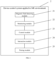
- FIG 2 is a block diagram of a functional module of the device control system applicable to the MR environment according to an embodiment of the present application.
- the device control system 2 applicable to the MR environment is provided in the first device, and the control system 2 includes a magnetic field detecting module 21, a monitoring module 22, and a control module 23, and each module is described separately below.
- control module 23 may include an alarm module and a brake module, to control the first device in conjunction with the multi-level alarm generated by the monitoring module 22.
- the alarm command received by the control module 23 is the first alarm command
- only the alarm module is called for alarming to remind the user to transfer the first device away from the current position.
- both the alarm module and the brake module are called.
- the alarm is performed by the alarm module to remind the user to transfer the first device away from the current position
- the brake is performed by the brake module to put the first device into the braked state so as to prevent the first device from colliding with the second device before the user operates it.
- the device control system 2 further includes an interaction module 24 and a timing module 25.
- the interaction module 24 is configured to receive a release command issued by the user when the first device is in the braked state and send the release command to the brake module.
- the brake module is configured to release the braked state of the first device after receiving the release command, so that the user can transfer the first device away from its current position.
- the timing module 25 is configured to start timing after the braked state of the first device is released. After T seconds, the magnetic field detecting module determines a current magnetic field intensity at the location of the first device. If the current magnetic field intensity is greater than the first threshold value, a lock command is generated and the lock command is sent to the brake module. In this case, it means that the user does not transfer the first device away from the dangerous position after issuing the release command. Therefore, in order to prevent a collision, the timing module 25 issues a lock command to cause the brake module to perform a locking process to lock the wheels of the first device, thereby achieving a secondary protection for the device.
- the device control system 2 further includes an electromagnetic shielding module.
- the electromagnetic shielding module wraps the brake module to shield the influence of electromagnetic field on the brake module, thereby enhancing the reliability of the control system 2.
- the device control apparatus applicable to the MR environment determines the magnetic field intensity at the location of the first device through the magnetic field detecting module, and then determines the risk of the first device being attracted to the second device according to the magnetic field intensity, so as to control the first device before the attraction occurs, thereby avoiding the collision between devices and enhancing the safety of the devices in the MR environment.
- the multi-level alarm command is used to achieve a multi-level control of the first device, thus making the control process more accurate and convenient.
- the first device is further detected twice by the timing module to ensure that the user transfers the first device away from the dangerous position, and the wheels of the first device are locked if the user does not transfer the first device away from the dangerous position, thereby achieving a secondary protection of the device.
- FIG 4 is a block diagram of a functional module of another device control system applicable to the MR environment according to an embodiment of the present application.
- the device control system 4 applicable to the MR environment is provided in the first device, and the control system 4 includes a distance detecting module 41, a monitoring module 42, a control module 43, an interaction module 44 and a timing module 45.
- the specific implementation process of the monitoring module 42, control module 43, interaction module 44 and timing module 45 is similar to that of the monitoring module 22, control module 23, interaction module 24 and timing module 25 of control system 2 in FIG 2 , and will not be repeated herein.
- the distance detecting module 41 will be described as follow.
- the distance detecting module 41 is configured to determine a distance between the first device and a second device.
- the risk level of the first device being attracted to the second device can be determined according to the distance between the first device and the second device.
- any distance measurement method based on electromagnetic correlation will be affected to a certain extent, leading to a decrease in distance measurement accuracy and affecting the control accuracy and efficiency of the control system.
- the distance detecting module 41 may include an infrared emitting module, an infrared receiving module, and a processing module.
- the infrared emitting module is provided at a position on the first device facing the second device and is configured to transmit an infrared light to the second device.
- the infrared receiving module is configured to receive the infrared light reflected by the second device.
- the processing module is configured to determine a distance between the first device and the second device according to an emission time of the infrared emitting module emitting the infrared light to the second device and a reception time of the infrared receiving module receiving the infrared light reflected by the second device.
- the distance between the two devices is determined by determining the time from the emission to the reflection of infrared light.
- the distance detecting module 41 may include a processing module.
- the processing module is specifically configured to: obtain a three-dimensional point cloud space and mark the second device as an origin of the three-dimensional point cloud space; obtain at least one image containing the first device from at least one camera module and determine at least one pixel coordinate of the first device in the at least one image; determine a spatial coordinate of the first device in the three-dimensional point cloud space according to the at least one pixel coordinate and the at least one camera module, and take a distance between the spatial coordinate and the origin as the distance between the first device and the second device.
- the three-dimensional point cloud space is obtained by pre-scanning the real space where the MR environment is located by a simultaneous localization and mapping device. After generating the three-dimensional point cloud space, the second device is set as the origin, and the camera module set in the MR environment is mapped to the corresponding position in the three-dimensional point cloud space.
- the multi-level alarm command is also configured to achieve the multi-level control of the first device.
- the alarm command generated by the monitoring module 42 is the first alarm command
- the first alarm command is configured to raise an alarm to remind the user to transfer the first device away from its current position. This is because there is a risk of attraction to the device at this distance, but the risk level is relatively low. In other words, there is a possibility of being attracted, but the possibility is too low to be negligible. Therefore, there is no need to control the first device, but only to issue an alarm to remind the user to transfer the first device away from its current position.
- the alarm command generated by the monitoring module 42 is a second alarm command, in which the fourth threshold is less than the second threshold.
- the second alarm command is configured to issue the alarm and control the first device to enter the braked state. This is because there is a risk of attraction to the device at this distance, and the risk level is high. In other words, the possibility of being attracted leading to a collision is high, and emergency braking means are required to prevent the device from colliding. Therefore, in addition to issuing an alarm, it is necessary to control the first device to enter a braked state.
- the device control system 4 further includes an electromagnetic shielding module.
- the electromagnetic shielding module wraps around the distance detecting module 41 and the brake module to shield the influence of electromagnetic field on the distance detecting module 41 and the brake module, thereby enhancing the reliability of the control system 2.
- the distance between the first device and the second device is determined by the distance detecting module, and then the risk of the first device being attracted to the second device is determined according to the distance between the first device and the second device, so as to control the first device before the attraction occurs, thereby avoiding the collision between the devices and enhancing the safety of the device in the MR environment.
- the multi-level alarm command is used to achieve the multi-level control of the first device, thereby making the control process more accurate and convenient.
- FIG 5 a block diagram of a functional module of another device control system applicable to the MR environment according to an embodiment of the present application.
- the device control system 5 applicable to the MR environment is provided in the first device, and the control system 5 includes a magnetic field detecting module 51, a distance detecting module 52, a monitoring module 53, a control module 54, an interaction module 55, and a timing module 56.
- the specific implementation process of the magnetic field detecting module 51, the monitoring module 53, the control module 54, the interaction module 55 and the timing module 56 is similar to the specific implementation process of the magnetic field detecting module 21, the monitoring module 22, the control module 23, the interaction module 24 and the timing module 25 of the control system 2 in FIG 2 , and will not be repeated herein.
- the specific implementation process of the distance detecting module 52 is similar to the specific implementation process of the distance detecting module 41 of the control system 2 in FIG 4 , and will not be repeated herein.
- the device control system 5 further includes an electromagnetic shielding module.
- the electromagnetic shielding module wraps around the distance detecting module 52 and the brake module to shield the influence of electromagnetic field on the distance detecting module 52 and the brake module, thereby enhancing the reliability of the control system 2.
- the magnetic field intensity at the location of the first device is determined by the magnetic field detecting module
- the distance between the first device and the second device is determined by the distance detecting module
- the risk of the first device being attracted to the second device is determined according to the magnetic field intensity and the distance between the first device and the second device, forming a double insurance. Therefore, the first device is controlled before the attraction occurs, thereby avoiding collisions between devices and enhancing the safety of the device in the MR environment.
- FIG 6 a structural schematic diagram of a device control apparatus applicable to the MR environment according to an embodiment of the present application.
- the device control apparatus applicable to the MR environment is provided in the first device, and the control device includes a processing unit 61, a Gauss meter 62, a distance sensor 63, a brake module 64, an alarm 65, a tricolor warning light 66, and a digital display 67.
- the processing unit 61 is connected to the Gauss meter 62, the distance sensor 63, the brake module 64, the tricolor warning light 66, and the digital display 67, respectively.
- the alarm 65 is connected to the processing unit 61 through the tricolor warning light 66.
- the alarm 65, tricolor warning light 66 and digital display 67 form an acousto-optical alarm module, and an area where the brake module 64 and the distance sensor 63 are located is an electromagnetic shielded area.
- control unit 6 operates as follows.
- the distance sensor 63 starts working for real-time distance detecting.
- the acquired distance value is greater than DT1 (the warning distance value DT1, when the device is in this position, there is a risk of being attracted, but the risk level is low and no emergency braking means is required)
- the control device does not take any action and the distance sensor 63 continues to work.
- the acquired distance value is less than DT1
- a pre-alarming signal is issued through the acousto-optical alarm module to remind the operator to transfer the device and avoid collision.
- the distance value is further determined. If the distance value is less than DT2 (dangerous distance value DT2, when the device is in this position, there is a risk of being attracted, and the risk level is high, so that the emergency braking means need to be taken to prevent device collision), the brake module 64 is started to brake the first device. If the distance value is greater than DT2, the brake module 64 will not start.
- DT2 angerous distance value DT2
- the Gauss meter 62 also starts to detect the magnetic field intensity in real time.
- GT1 warning magnetic field intensity value
- the control device does not take any action, and the Gauss meter 62 continues to work.
- GT1 warning magnetic field intensity value
- the control device does not take any action, and the Gauss meter 62 continues to work.
- the acquired Gauss meter value is greater than GT1
- a warning alarm signal is issued by through the acousto-optical alarm module to remind the operator to transfer the device and avoid collision.
- the magnetic field intensity value is further determined. If the magnetic field intensity value is greater than GT2 (dangerous magnetic field intensity value GT2, when the device is in this position, there is a risk of being attracted, and the risk level is very high, so that emergency braking means are required to prevent device collision), the brake module 64 is started to brake the first device. If the magnetic field intensity value is less than GT2, the brake module 64 will not start.
- GT2 angerous magnetic field intensity value GT2
- the signal is transmitted to a signal receiver at the brake device. After receiving the signal, the braking device is immediately activated to stop the cart and prevent further collision close to the second device.
- the operator can temporarily release the brake device through the digital display 67 to temporarily release the brake device and move the device away from the dangerous position. After disengagement, the control device is reset.
- the brake device will hold and protect the device twice.
- FIG 8 a flowchart of a device control method applicable to the MR environment according to an embodiment of the present application. As shown in FIG 8 , the device control method applicable to the MR environment includes the following steps.
- a magnetic field intensity at a location of the first device is determined; and/or, a distance between the first device and a second device is determined.
- an alarm command is generated according to the magnetic field intensity and/or the distance.
- the first device is controlled according to the alarm command.
- FIG 9 a structural schematic diagram of an electronic device according to an embodiment of the present application.
- the electronic device 900 includes a transceiver 901, a processor 902, and a memory 903, which are connected to each other through a bus 904.
- the memory 903 is configured to store computer programs and data and can transfer the data stored in the memory 903 to the processor 902.
- the processor 902 is configured to read the computer program in the memory 903 to perform the following operations.
- a magnetic field intensity at a location of the first device is determined; and/or, a distance between the first device and a second device is determined.
- An alarm command is generated according to the magnetic field intensity and/or the distance.
- the first device is controlled according to the alarm command. It should be understood that the specific implementation process of the individual operations performed by the processor 902 shown in FIG 9 can be found in the specific implementation process of the individual modules in the system described in any of FIG 2 , FIG 4 and FIG 5 above, and will not be repeated herein.
- the device control apparatus applicable to the MR environment in the present application may be a smartphone (e.g., Android phone, iOS phone, Windows Phone), a tablet computer, a handheld computer, a laptop computer, a mobile Internet device (MID), a robot or a wearable device, etc.
- the above-mentioned device control apparatus applicable to the MR environment are only examples, not an exhaustive list, which is but not limited to the above-mentioned device control apparatus applicable to the MR environment. In practical applications, the above-mentioned device control apparatus applicable to MR environment may also be an intelligent vehicle terminal or a computer device.
- the present application embodiment further provides a computer-readable storage medium.
- the computer-readable storage medium stores a computer program, and the computer program is executed by a processor to implement some or all of the steps of the device control method applicable to the MR environment as described in the above-method embodiments.
- the storage medium may be a hard disk, a floppy disk, an optical disk, a magnetic tape, a diskette, a thumb drive, a flash memory, etc.
- Embodiments of the present application further provide a computer program product, including a non-transitory computer-readable storage medium storing a computer program, the computer program being operable to cause the computer to perform some or all of the steps of the device control method applicable to the MR environment as described in the above-method embodiments.
- the disclosed apparatuses may be implemented in other ways.
- the above described embodiments of the device are only schematic.
- the division of the units described, is only a logical functional division, and the practical embodiment may be divided in another way. Multiple units or components may be combined or integrated into another system, or some features may be ignored or not implemented.
- the mutual coupling or direct coupling or communication connections shown or discussed may be indirect coupling or communication connections through some interface, device or unit, either electrically or in other forms.
- the units illustrated as separate components may or may not be physically separated, and the components shown as units may or may not be physical units, i.e., may be located in one place or may also be distributed to a plurality of network units. Some or all of these units may be selected according to practical needs to achieve the purpose of the scheme of the embodiments.
- each functional unit in each embodiment of the present application may be integrated in a processing unit, or each unit may be physically present separately, or two or more units may be integrated in a single unit.
- the integrated units may be implemented either in the form of hardware or in the form of software program modules.
- the integrated unit when implemented in the form of a software program module and sold or used as a separate product, may be stored in a computer-readable memory. It is understood that the technical solution of the present application, or that part or all or part of the technical solution which essentially contributes to the prior art, may be embodied in the form of a software product.
- the software product is stored in a memory and includes a number of instructions to enable a computer device (which may be a personal computer, server or network device, etc.) to perform all or part of the steps of the method described in the various embodiments of the present application.
- the above-mentioned memory may be USB flash drive, Read-Only Memory (ROM), Random Access Memory (RAM), removable hard disk, diskette, or CD-ROM, and various other media that can store program code.
- the person having ordinary skill in the art can understand that all or some of the steps in the various methods of the above embodiments may be accomplished by instructing the relevant hardware through a program, which may be stored in a computer-readable memory.
- the memory may be a flash drive, Read-Only Memory (ROM), Random Access Memory (RAM), disk or CD-ROM, etc.
Landscapes
- Engineering & Computer Science (AREA)
- Automation & Control Theory (AREA)
- Health & Medical Sciences (AREA)
- Transportation (AREA)
- Mechanical Engineering (AREA)
- Surgery (AREA)
- Physics & Mathematics (AREA)
- Life Sciences & Earth Sciences (AREA)
- Human Computer Interaction (AREA)
- Condensed Matter Physics & Semiconductors (AREA)
- Medical Informatics (AREA)
- Pathology (AREA)
- Nuclear Medicine, Radiotherapy & Molecular Imaging (AREA)
- General Physics & Mathematics (AREA)
- Biomedical Technology (AREA)
- Heart & Thoracic Surgery (AREA)
- Oral & Maxillofacial Surgery (AREA)
- Molecular Biology (AREA)
- Animal Behavior & Ethology (AREA)
- General Health & Medical Sciences (AREA)
- Public Health (AREA)
- Veterinary Medicine (AREA)
- Magnetic Resonance Imaging Apparatus (AREA)
- Traffic Control Systems (AREA)
Abstract
Description
- The present disclosure generally relates to the field of device control technologies, and more particularly, to a device control system, a method, an electronic device, and a storage medium applicable to an MR environment.
- Magnetic Resonance Imaging (MRI) is a widely used medical imaging technique that utilizes the phenomenon of magnetic resonance to obtain electromagnetic signals from the human body and reconstruct information and tomographic images. The environment in which MRI is performed is referred to as the Magnetic Resonance (MR) environment. While MRI offers advantages such as a variety of imaging modalities and rich information, its strong magnetic field characteristic also brings certain inconveniences. For instance, there is a risk of magnetization of metallic enclosures in the MR environment.
- In the case of devices that needs to be frequently moved within the MR environment, such as ventilators, they are typically placed on carts with wheels for ease of mobility. However, in the MR environment, the magnetized metallic enclosures of these devices can generate magnetic attraction and gravitational force between these devices and other devices within the MR environment. This can lead to unintended movement of the cart and ultimately result in collisions. These collisions can cause significant damage and financial losses, especially for costly MRI devices such as imaging machines.
- In order to solve the above-mentioned problems in the prior art, embodiments of the present application provide a device control apparatus, method, electronic device, and storage medium applied to the MR environment, which can stop the movement of the device before the device collision and prevent the damage caused by the device collision.
- According to a first aspect, embodiments of the present application provide a device control system applicable to a Magnetic Resonance (MR) environment, comprising:
- a magnetic field detecting module configured to determine a magnetic field intensity at a location of a first device; and/or, a distance detecting module configured to determine a distance between the first device and a second device;
- a monitoring module configured to generate an alarm command according to the magnetic field intensity and/or the distance; and
- a control module configured to control the first device according to the alarm command.
- According to a second aspect, embodiments of the present application provide a device control method applicable to a Magnetic Resonance (MR) environment, comprising:
- determining a magnetic field intensity at a location of a first device; and/or, determining a distance between the first device and a second device;
- generating an alarm command according to the magnetic field intensity and/or the distance; and
- controlling the first device according to the alarm command.
- According to a third aspect, embodiments of the present application provide an electronic device, comprising a processor, a memory, a communication interface, and one or more programs; wherein the one or more programs are stored in the memory, when executed by the processor, causing the electronic device to perform the steps in the method as described in the second aspect.
- According to a fourth aspect, embodiments of the present application provide a computer-readable storage medium, wherein the computer-readable storage medium stores a computer program, causing a computer to implement the method as described in the second aspect.
- According to a fifth aspect, embodiments of the present application provide a computer program product, comprising a non-transitory computer-readable storage medium on which a computer program is stored, the computer program being operable to cause a computer to perform a method as described in the second aspect.
- The embodiments of the present application to be implemented may have the following beneficial effects.
- As can be seen, in the embodiments of the present application, the magnetic field intensity of the location of the first device is determined by the magnetic field detecting module, and the distance between the first device and the second device is determined by the distance detecting module, and then the risk of the first device being attracted to the second device is determined according to the magnetic field intensity and distance, so that the first device is controlled before the attraction occurs, thereby avoiding collisions between devices, improving the safety of the devices in the MR environment, and preventing losses due to device collisions.
- In order to illustrate the technical solutions in the embodiments of the present application more clearly, the accompanying drawings to be used in the description of the embodiments will be briefly described below. Obviously, the accompanying drawings in the following description are some embodiments of the present application, for a person having ordinary skill in the art, other accompanying drawings can be obtained without creative work.
-
FIG 1 shows an application scenario of a device control system applicable to a Magnetic Resonance (MR) environment according to an embodiment of the present application. -
FIG 2 is a block diagram of a functional module of the device control system applicable to the MR environment according to an embodiment of the present application. -
FIG 3 shows a distribution of non-ferrous metal particles in a magnetorheological fluid at different magnetic field intensities. -
FIG 4 is a block diagram of a functional module of another device control system applicable to the MR environment according to an embodiment of the present application. -
FIG 5 a block diagram of a functional module of another device control system applicable to the MR environment according to an embodiment of the present application. -
FIG 6 a structural schematic diagram of a device control apparatus applicable to the MR environment according to an embodiment of the present application. -
FIG 7 is an operation flowchart of the device control apparatus applicable to the MR environment according to an embodiment of the present application. -
FIG 8 a flowchart of a device control method applicable to the MR environment according to an embodiment of the present application. -
FIG 9 a structural schematic diagram of an electronic device according to an embodiment of the present application. - The technical solutions in the embodiments of the present application will be described clearly and completely as follows in conjunction with the accompanying drawings in the embodiments of the present application, and it is clear that the embodiments described are a part of rather than all of the embodiments of the present application. Based on the embodiments in the present application, all other embodiments obtained by a person having ordinary skill in the art without creative labor fall within the protection scope of the present application.
- The terms "first", "second", "third", and "fourth" in the specification and claims of the present application and the accompanying drawings described herein are used to distinguish between different objects but not used to describe a particular order. In addition, the terms "include" and "have", and any variations thereof, are intended to cover non-exclusive inclusion. For example, a process, method, system, product, or device that includes a series of steps or units is not limited to the listed steps or units, but optionally also includes steps or units that are not listed, or optionally also includes other steps or units that are inherent to the process, method, system, product, or device.
- References herein to "embodiment" mean that particular features, results, or characteristics described in conjunction with an embodiment may be included in at least one embodiment of the present application. The presence of this item at various points in the specification does not necessarily mean the same embodiment, nor is it a separate or alternative embodiment that is mutually exclusive with other embodiments. It is understood, both explicitly and implicitly, by the person having ordinary skill in the art that the embodiments described herein may be combined with other embodiments.
- Referring to
FIG 1, FIG 1 shows an application scenario of a device control system applicable to a Magnetic Resonance (MR) environment according to an embodiment of the present application. - A
first device 11 is a movable device with wheels, and thecontrol system 10 is provided in the first device. A second device 12 is a non-movable device fixed in the MR environment. A distance between thefirst device 11 and the second device 12 is X, and there is a magnetic field sequentially outwardly decreasing around the second device 12. - In this embodiment, the
control system 10 can determine a magnetic field intensity at a location of thefirst device 11 and/or a distance between thefirst device 11 and the second device 12. Thecontrol system 10 further determines a risk level of mutual attraction based on the magnetic field intensity and/or the distance. If the risk level is too high, thecontrol system 10 generates an alarm command, to control thefirst device 10 to enter a braked state, thereby preventing great damage due to the collision of the first device with the second device. - Referring to
FIG 2, FIG 2 is a block diagram of a functional module of the device control system applicable to the MR environment according to an embodiment of the present application. Thedevice control system 2 applicable to the MR environment is provided in the first device, and thecontrol system 2 includes a magneticfield detecting module 21, amonitoring module 22, and acontrol module 23, and each module is described separately below. - (1) The magnetic
field detecting module 21 is configured to determine the magnetic field intensity at a location of the first device.
Due to the fixed positioning of the second device within the MR environment, the surrounding magnetic field intensity is also constant. Therefore, the distance relationship between the first device and the second device can be determined by obtaining the magnetic field intensity at the location of the first device. Generally speaking, a Gauss meter may be used as the magneticfield detecting module 21. However, the Gauss meter is tested in a point test manner, which has the defects of inaccurate measurement, different values measured by different manufacturers of Gauss meter, and different values measured by different probes of the same Gauss meter. Therefore, the test data of Gauss meter has great dispersion and cannot accurately obtain the magnetic field intensity at a certain location.
Therefore, the present application provides a magneticfield detecting module 21. Exemplarily, the magneticfield detecting module 21 may include a closed container, a light intensity detecting module, a light emitting module, and a processing module. The closed container is filled with a magnetorheological fluid, and the magnetorheological fluid is mixed with non-ferrous metal particles. The light emitting module is provided at a bottom end of the closed container and is configured to emit a light beam to irradiate the light intensity detecting module. The light intensity detecting module is provided at a top end of the closed container and is configured to detect a light intensity of the light beam irradiated by the light emitting module and send the light intensity to the processing module. The processing module is configured to receive the light intensity and determine the magnetic field intensity according to the light intensity.
Specifically, the magnetorheological fluid (MR fluid) is a new fluid with controlled fluidity. It exhibits low viscosity Newtonian fluid properties in the absence of an external magnetic field, and appears as a Bingham fluid with high viscosity and low flowability when a magnetic field is applied. There is a corresponding relationship between the viscosity of the fluid and the magnetic flux. Moreover, the magnetorheological fluid with such viscosity and flowability has advantages of low energy consumption, easy to control, and fast response (milliseconds).
Under this liquid characteristic, as shown inFIG 3(a) , the non-ferrous metal particles in the magnetorheological liquid show an irregular and disordered distribution in the absence of magnetic field, and this disordered distribution leads to a low transmittance of the magnetorheological liquid. In contrast, when the magnetic field is applied, as shown inFIGS. 3(b) and 3(c) , the non-ferrous metal particles form a chain-like distribution with the direction of the magnetic field, and the stronger the magnetic field is, the more regular the chains formed. Besides, gaps are formed between the chains, leading to a larger transmittance of the magnetorheological fluid. Therefore, the magnetic field intensity of the environment can be accurately determined based on the difference in the transmittance of the magnetorheological fluid with non-ferrous metal particles at different magnetic field intensities.
In addition, in the embodiment, the light emitted by the light emitting module may be a high frequency and highly penetrating violet light. The non-ferrous metal particles may be iron particles with lower cost and good magnetic properties. The diameter of iron particles is preferably 1.2-1.6 um, so that the detection accuracy of the magneticfield detecting module 21 can be further improved, and the costs are reduced.
In an optional embodiment, thecontrol system 2 may include at least two magneticfield detecting modules 21, thereby preventing the system from being paralyzed in case one of them fails. Additionally, the presence of multiple magneticfield detecting modules 21 allows for comparing their respective measurement results, thereby improving the measurement accuracy and optimizing the control of the first device by thecontrol system 2. - (2) The
monitoring module 22 is configured to generate an alarm command according to the magnetic field intensity.
In this embodiment, a multi-level alarm command is used to achieve a multi-level control of the first device. Exemplarily, when the magnetic field intensity is greater than a first threshold value, the alarm command is a first alarm command, and the first alarm command only serves to raise an alarm to remind the user to transfer the first device away from its current position. This is because there is a risk of attraction to the device in this environment, but the risk level is relatively low. In other words, there is a possibility of being attracted, but the possibility is too low to be negligible. Therefore, there is no need to control the first device, but only to issue an alarm to remind the user to transfer the first device away from its current position.
When the magnetic field intensity is greater than a third threshold value, the alarm command is a second alarm command, in which the third threshold value is greater than the first threshold value. The second alarm command is configured to issue the alarm and control the first device to enter a braked state. This is because there is a risk of attraction to the device in this environment, and the risk level is high. In other words, the possibility of being attracted leading to a collision is high, and emergency braking means are required to prevent the device from colliding. Therefore, in addition to issuing an alarm, it is necessary to control the first device to enter a braked state.
In an optional embodiment, the present application further provides a client for receiving alarm commands issued by themonitoring module 22. The client may include a smartphone (such as an Android phone, an iPhone Operating System (iOS) phone, a Windows Phone), a tablet computer, a palmtop computer, a laptop computer, a Mobile Internet Device (MID), and other electronic devices that can receive information. When the client is a small movable electronic device such as a smartphone, it can be carried by the user at any time so that the user can be informed in a timely manner through the client when an alarm occurs, and thus send feedback commands to thecontrol system 2 through the client to pre-process the alarm.
In an optional embodiment, the present application further provides a server, which is configured to receive the alarm command issued by thecontrol system 2, receive the feedback commands sent by the client, and store the alarm command and feedback commands for easy analysis and recall later. - (3) The
control module 23 is configured to control the first device according to the alarm command. - In this embodiment, the
control module 23 may include an alarm module and a brake module, to control the first device in conjunction with the multi-level alarm generated by themonitoring module 22. - Exemplarily, when the alarm command received by the
control module 23 is the first alarm command, only the alarm module is called for alarming to remind the user to transfer the first device away from the current position. When the alarm command received by thecontrol module 23 is the second alarm command, both the alarm module and the brake module are called. Specifically, the alarm is performed by the alarm module to remind the user to transfer the first device away from the current position, and at the same time, the brake is performed by the brake module to put the first device into the braked state so as to prevent the first device from colliding with the second device before the user operates it. - Referring to
FIG 2 , in this embodiment, thedevice control system 2 further includes aninteraction module 24 and atiming module 25. Theinteraction module 24 is configured to receive a release command issued by the user when the first device is in the braked state and send the release command to the brake module. The brake module is configured to release the braked state of the first device after receiving the release command, so that the user can transfer the first device away from its current position. - In this embodiment, the
timing module 25 is configured to start timing after the braked state of the first device is released. After T seconds, the magnetic field detecting module determines a current magnetic field intensity at the location of the first device. If the current magnetic field intensity is greater than the first threshold value, a lock command is generated and the lock command is sent to the brake module. In this case, it means that the user does not transfer the first device away from the dangerous position after issuing the release command. Therefore, in order to prevent a collision, thetiming module 25 issues a lock command to cause the brake module to perform a locking process to lock the wheels of the first device, thereby achieving a secondary protection for the device. - In addition, in this embodiment, the
device control system 2 further includes an electromagnetic shielding module. The electromagnetic shielding module wraps the brake module to shield the influence of electromagnetic field on the brake module, thereby enhancing the reliability of thecontrol system 2. - In summary, the device control apparatus applicable to the MR environment provided by the present application determines the magnetic field intensity at the location of the first device through the magnetic field detecting module, and then determines the risk of the first device being attracted to the second device according to the magnetic field intensity, so as to control the first device before the attraction occurs, thereby avoiding the collision between devices and enhancing the safety of the devices in the MR environment. Besides, the multi-level alarm command is used to achieve a multi-level control of the first device, thus making the control process more accurate and convenient. In addition, after the user issues a release command, the first device is further detected twice by the timing module to ensure that the user transfers the first device away from the dangerous position, and the wheels of the first device are locked if the user does not transfer the first device away from the dangerous position, thereby achieving a secondary protection of the device.
- Referring to
FIG 4, FIG 4 is a block diagram of a functional module of another device control system applicable to the MR environment according to an embodiment of the present application. Thedevice control system 4 applicable to the MR environment is provided in the first device, and thecontrol system 4 includes adistance detecting module 41, amonitoring module 42, acontrol module 43, aninteraction module 44 and atiming module 45. The specific implementation process of themonitoring module 42,control module 43,interaction module 44 andtiming module 45 is similar to that of themonitoring module 22,control module 23,interaction module 24 andtiming module 25 ofcontrol system 2 inFIG 2 , and will not be repeated herein. - The
distance detecting module 41 will be described as follow. - In this embodiment, the
distance detecting module 41 is configured to determine a distance between the first device and a second device. - In this embodiment, since the magnetic field intensity around the second device is a given, the risk level of the first device being attracted to the second device can be determined according to the distance between the first device and the second device.
- Since the MR environment is a special environment in a strong magnetic field, any distance measurement method based on electromagnetic correlation will be affected to a certain extent, leading to a decrease in distance measurement accuracy and affecting the control accuracy and efficiency of the control system.
- Therefore, in this embodiment, the
distance detecting module 41 may include an infrared emitting module, an infrared receiving module, and a processing module. The infrared emitting module is provided at a position on the first device facing the second device and is configured to transmit an infrared light to the second device. The infrared receiving module is configured to receive the infrared light reflected by the second device. The processing module is configured to determine a distance between the first device and the second device according to an emission time of the infrared emitting module emitting the infrared light to the second device and a reception time of the infrared receiving module receiving the infrared light reflected by the second device. The distance between the two devices is determined by determining the time from the emission to the reflection of infrared light. This method has the advantages of fast positioning, simple operation, high accuracy, and is not easily affected by strong magnetic fields. - In an optional embodiment, the
distance detecting module 41 may include a processing module. The processing module is specifically configured to:
obtain a three-dimensional point cloud space and mark the second device as an origin of the three-dimensional point cloud space; obtain at least one image containing the first device from at least one camera module and determine at least one pixel coordinate of the first device in the at least one image; determine a spatial coordinate of the first device in the three-dimensional point cloud space according to the at least one pixel coordinate and the at least one camera module, and take a distance between the spatial coordinate and the origin as the distance between the first device and the second device. - Exemplarily, the three-dimensional point cloud space is obtained by pre-scanning the real space where the MR environment is located by a simultaneous localization and mapping device. After generating the three-dimensional point cloud space, the second device is set as the origin, and the camera module set in the MR environment is mapped to the corresponding position in the three-dimensional point cloud space.
- As a result, after obtaining the at least one image containing the first device, and the camera modules that took the image feedback their shooting angle information, and the pixel coordinate of the first device in each image is obtained through image processing. Thus, by combining the shooting angle information and pixel coordinates returned by multiple camera modules, a corresponding scene can be constructed in the three-dimensional point cloud space, and the spatial coordinates of the first device in the three-dimensional point cloud space can be determined. This method can accurately determine the location of the first device with almost negligible error, which can greatly improve the control accuracy and efficiency of the control system.
- In addition, in this embodiment, the multi-level alarm command is also configured to achieve the multi-level control of the first device. Exemplarily, when the distance between the first device and the second device is less than the second threshold, the alarm command generated by the
monitoring module 42 is the first alarm command, and the first alarm command is configured to raise an alarm to remind the user to transfer the first device away from its current position. This is because there is a risk of attraction to the device at this distance, but the risk level is relatively low. In other words, there is a possibility of being attracted, but the possibility is too low to be negligible. Therefore, there is no need to control the first device, but only to issue an alarm to remind the user to transfer the first device away from its current position. - When the distance between the first device and the second device is less than the fourth threshold, the alarm command generated by the
monitoring module 42 is a second alarm command, in which the fourth threshold is less than the second threshold. The second alarm command is configured to issue the alarm and control the first device to enter the braked state. This is because there is a risk of attraction to the device at this distance, and the risk level is high. In other words, the possibility of being attracted leading to a collision is high, and emergency braking means are required to prevent the device from colliding. Therefore, in addition to issuing an alarm, it is necessary to control the first device to enter a braked state. - In addition, in this embodiment, the
device control system 4 further includes an electromagnetic shielding module. The electromagnetic shielding module wraps around thedistance detecting module 41 and the brake module to shield the influence of electromagnetic field on thedistance detecting module 41 and the brake module, thereby enhancing the reliability of thecontrol system 2. - In summary, in the device control apparatus applicable to the MR environment provided by the present application, the distance between the first device and the second device is determined by the distance detecting module, and then the risk of the first device being attracted to the second device is determined according to the distance between the first device and the second device, so as to control the first device before the attraction occurs, thereby avoiding the collision between the devices and enhancing the safety of the device in the MR environment. Besides, the multi-level alarm command is used to achieve the multi-level control of the first device, thereby making the control process more accurate and convenient.
- Referring to
FIG 5, FIG 5 a block diagram of a functional module of another device control system applicable to the MR environment according to an embodiment of the present application. Thedevice control system 5 applicable to the MR environment is provided in the first device, and thecontrol system 5 includes a magneticfield detecting module 51, adistance detecting module 52, amonitoring module 53, acontrol module 54, aninteraction module 55, and atiming module 56. - The specific implementation process of the magnetic
field detecting module 51, themonitoring module 53, thecontrol module 54, theinteraction module 55 and thetiming module 56 is similar to the specific implementation process of the magneticfield detecting module 21, themonitoring module 22, thecontrol module 23, theinteraction module 24 and thetiming module 25 of thecontrol system 2 inFIG 2 , and will not be repeated herein. - The specific implementation process of the
distance detecting module 52 is similar to the specific implementation process of thedistance detecting module 41 of thecontrol system 2 inFIG 4 , and will not be repeated herein. - In addition, in this embodiment, the
device control system 5 further includes an electromagnetic shielding module. The electromagnetic shielding module wraps around thedistance detecting module 52 and the brake module to shield the influence of electromagnetic field on thedistance detecting module 52 and the brake module, thereby enhancing the reliability of thecontrol system 2. - In summary, in the device control apparatus applicable to the MR environment provided by the present application, the magnetic field intensity at the location of the first device is determined by the magnetic field detecting module, the distance between the first device and the second device is determined by the distance detecting module, and then the risk of the first device being attracted to the second device is determined according to the magnetic field intensity and the distance between the first device and the second device, forming a double insurance. Therefore, the first device is controlled before the attraction occurs, thereby avoiding collisions between devices and enhancing the safety of the device in the MR environment.
- Referring to
FIG 6, FIG 6 a structural schematic diagram of a device control apparatus applicable to the MR environment according to an embodiment of the present application. The device control apparatus applicable to the MR environment is provided in the first device, and the control device includes aprocessing unit 61, aGauss meter 62, adistance sensor 63, abrake module 64, analarm 65, atricolor warning light 66, and adigital display 67. - The
processing unit 61 is connected to theGauss meter 62, thedistance sensor 63, thebrake module 64, thetricolor warning light 66, and thedigital display 67, respectively. Thealarm 65 is connected to theprocessing unit 61 through thetricolor warning light 66. Thealarm 65,tricolor warning light 66 anddigital display 67 form an acousto-optical alarm module, and an area where thebrake module 64 and thedistance sensor 63 are located is an electromagnetic shielded area. - Exemplarily, as shown in
FIG 7 , the control unit 6 operates as follows. - When the control device 6 is started, the
distance sensor 63 starts working for real-time distance detecting. When the acquired distance value is greater than DT1 (the warning distance value DT1, when the device is in this position, there is a risk of being attracted, but the risk level is low and no emergency braking means is required), the control device does not take any action and thedistance sensor 63 continues to work. When the acquired distance value is less than DT1, a pre-alarming signal is issued through the acousto-optical alarm module to remind the operator to transfer the device and avoid collision. - While issuing the pre-alarming signal by the acousto-optical alarm module, the distance value is further determined. If the distance value is less than DT2 (dangerous distance value DT2, when the device is in this position, there is a risk of being attracted, and the risk level is high, so that the emergency braking means need to be taken to prevent device collision), the
brake module 64 is started to brake the first device. If the distance value is greater than DT2, thebrake module 64 will not start. - At the same time, the
Gauss meter 62 also starts to detect the magnetic field intensity in real time. When the acquired Gauss meter value is less than GT1 (warning magnetic field intensity value GT1, when the device is in this kind of environment, there is a risk of being attracted, but the risk level is low and no emergency braking means is required), the control device does not take any action, and theGauss meter 62 continues to work. When the acquired Gauss meter value is greater than GT1, a warning alarm signal is issued by through the acousto-optical alarm module to remind the operator to transfer the device and avoid collision. - While issuing the pre-alarming signal through the acousto-optical alarm module, the magnetic field intensity value is further determined. If the magnetic field intensity value is greater than GT2 (dangerous magnetic field intensity value GT2, when the device is in this position, there is a risk of being attracted, and the risk level is very high, so that emergency braking means are required to prevent device collision), the
brake module 64 is started to brake the first device. If the magnetic field intensity value is less than GT2, thebrake module 64 will not start. - When the
brake module 64 starts, the signal is transmitted to a signal receiver at the brake device. After receiving the signal, the braking device is immediately activated to stop the cart and prevent further collision close to the second device. - The operator can temporarily release the brake device through the
digital display 67 to temporarily release the brake device and move the device away from the dangerous position. After disengagement, the control device is reset. - If the operator does not move the device away from the dangerous position within T seconds after releasing the braking device, the brake device will hold and protect the device twice.
- Referring to
FIG 8, FIG 8 a flowchart of a device control method applicable to the MR environment according to an embodiment of the present application. As shown inFIG 8 , the device control method applicable to the MR environment includes the following steps. - 801: a magnetic field intensity at a location of the first device is determined; and/or, a distance between the first device and a second device is determined.
- 802: an alarm command is generated according to the magnetic field intensity and/or the distance.
- 803: the first device is controlled according to the alarm command.
- It should be understood that the specific implementation process of the various steps of the method shown in
FIG 8 can be found in the specific implementation process of the various modules in the system described in any ofFIG 2 ,FIG 4 andFIG 5 above, and will not be repeated herein. - Referring to
FIG 9, FIG 9 a structural schematic diagram of an electronic device according to an embodiment of the present application. As shown inFIG 9 , theelectronic device 900 includes atransceiver 901, aprocessor 902, and amemory 903, which are connected to each other through abus 904. Thememory 903 is configured to store computer programs and data and can transfer the data stored in thememory 903 to theprocessor 902. - The
processor 902 is configured to read the computer program in thememory 903 to perform the following operations. - A magnetic field intensity at a location of the first device is determined; and/or, a distance between the first device and a second device is determined.
- An alarm command is generated according to the magnetic field intensity and/or the distance.
- The first device is controlled according to the alarm command. It should be understood that the specific implementation process of the individual operations performed by the
processor 902 shown inFIG 9 can be found in the specific implementation process of the individual modules in the system described in any ofFIG 2 ,FIG 4 andFIG 5 above, and will not be repeated herein. - It should be understood that the device control apparatus applicable to the MR environment in the present application may be a smartphone (e.g., Android phone, iOS phone, Windows Phone), a tablet computer, a handheld computer, a laptop computer, a mobile Internet device (MID), a robot or a wearable device, etc. The above-mentioned device control apparatus applicable to the MR environment are only examples, not an exhaustive list, which is but not limited to the above-mentioned device control apparatus applicable to the MR environment. In practical applications, the above-mentioned device control apparatus applicable to MR environment may also be an intelligent vehicle terminal or a computer device.
- Through the description of the above embodiments, it is clear to the person having ordinary skill in the art that the present application can be realized with the combination of software and a hardware platform. Based on this understanding, all or part of the technical solution of the present application that contributes to the background technologies may be embodied in the form of a software product, which may be stored in a storage medium, such as ROM/RAM, disk, CD-ROM, including a number of instructions to enable a computer device (which may be a personal computer, a server, or a network device, etc.) to execute the method described in each embodiment or some part of the embodiments of the present application.
- Accordingly, the present application embodiment further provides a computer-readable storage medium. The computer-readable storage medium stores a computer program, and the computer program is executed by a processor to implement some or all of the steps of the device control method applicable to the MR environment as described in the above-method embodiments. For example, the storage medium may be a hard disk, a floppy disk, an optical disk, a magnetic tape, a diskette, a thumb drive, a flash memory, etc.
- Embodiments of the present application further provide a computer program product, including a non-transitory computer-readable storage medium storing a computer program, the computer program being operable to cause the computer to perform some or all of the steps of the device control method applicable to the MR environment as described in the above-method embodiments.
- It should be noted that each of the above-mentioned method embodiments is presented as a series of combinations of actions for simplicity of description, but it should be known to the person having ordinary skill in the art that the present application is not limited by the sequence of actions described, as certain steps may be performed in other sequences or simultaneously according to the present application. Secondly, the person having ordinary skill in the art should also be aware that the embodiments described in the specification are optional and the actions and modules involved are not necessarily necessary for the present application.
- In the above embodiments, the description of each embodiment has its own focus, and what is not described in detail in a particular embodiment may be found in the relevant descriptions of other embodiments.
- In several of the embodiments provided in the present application, it should be understood that the disclosed apparatuses may be implemented in other ways. For example, the above described embodiments of the device are only schematic. The division of the units described, is only a logical functional division, and the practical embodiment may be divided in another way. Multiple units or components may be combined or integrated into another system, or some features may be ignored or not implemented. On another point, the mutual coupling or direct coupling or communication connections shown or discussed may be indirect coupling or communication connections through some interface, device or unit, either electrically or in other forms.
- The units illustrated as separate components may or may not be physically separated, and the components shown as units may or may not be physical units, i.e., may be located in one place or may also be distributed to a plurality of network units. Some or all of these units may be selected according to practical needs to achieve the purpose of the scheme of the embodiments.
- Additionally, each functional unit in each embodiment of the present application may be integrated in a processing unit, or each unit may be physically present separately, or two or more units may be integrated in a single unit. The integrated units may be implemented either in the form of hardware or in the form of software program modules.
- The integrated unit, when implemented in the form of a software program module and sold or used as a separate product, may be stored in a computer-readable memory. It is understood that the technical solution of the present application, or that part or all or part of the technical solution which essentially contributes to the prior art, may be embodied in the form of a software product. The software product is stored in a memory and includes a number of instructions to enable a computer device (which may be a personal computer, server or network device, etc.) to perform all or part of the steps of the method described in the various embodiments of the present application. The above-mentioned memory may be USB flash drive, Read-Only Memory (ROM), Random Access Memory (RAM), removable hard disk, diskette, or CD-ROM, and various other media that can store program code.
- The person having ordinary skill in the art can understand that all or some of the steps in the various methods of the above embodiments may be accomplished by instructing the relevant hardware through a program, which may be stored in a computer-readable memory. The memory may be a flash drive, Read-Only Memory (ROM), Random Access Memory (RAM), disk or CD-ROM, etc.
- The above is a detailed description of the embodiments of the present application, and this paper applies specific examples to illustrate the principle and embodiments of the present application. The above description is only for the purpose of helping to understand the method of the present application and its core idea. In addition, for the person having ordinary skill in the art, according to the idea of the present application, there will be changes in the specific embodiments and the scope of application. In summary, the content of this description should not be understood as a limitation of the present application.
Claims (10)
- A device control system applicable to a Magnetic Resonance (MR) environment, wherein the control system belongs to a first device, and the control system comprises:a magnetic field detecting module configured to determine a magnetic field intensity at a location of the first device; and/or, a distance detecting module configured to determine a distance between the first device and a second device;a monitoring module configured to generate an alarm command according to the magnetic field intensity and/or the distance; anda control module configured to control the first device according to the alarm command.
- The device control system of claim 1, whereinthe control module comprises an alarm module and a brake module;the alarm command is a first alarm command when the magnetic field intensity is greater than a first threshold and/or the distance is less than a second threshold, and the first alarm command is configured to instruct the alarm module to make an alarm to warn the user;the alarm command is a second alarm command when the magnetic field intensity is greater than a third threshold and/or the distance is less than a fourth threshold, and the second alarm command is configured to instruct the alarm module to make an alarm and instruct the brake module to make a brake to put the first device into a braked state;wherein the first threshold value is less than the third threshold value, and the second threshold value is greater than the fourth threshold value.
- The device control system of claim 2, further comprising:an interaction module configured to receive a release command and send the release command to the brake module when the first device is in the braked state;the brake module further configured to release the braked state of the first device according to the release command;a timing module configured to start a timing after releasing the braked state of the first device, so that the magnetic field detecting module determines a current magnetic field intensity at the location of the first device after T seconds, and/or, the distance detecting module determines a current distance between the first device and the second device after T seconds; andgenerate a lock command and send the lock command to the brake module if the current magnetic field intensity is greater than the first threshold and/or the current distance is less than the second threshold; andthe brake module further configured to perform a locking process to lock wheels of the first device according to the lock command.
- The device control system of claim 2, further comprising:
an electromagnetic shielding module configured to wrap the distance detecting module and the brake module to shield the distance detecting module and the brake module from an influence of electromagnetic fields. - The device control system of any one of claims 1-4, wherein the magnetic field detecting module, comprising:a closed container;a light intensity detecting module;a light emitting module; anda processing module;wherein the closed container is filled with a magnetorheological fluid, the magnetorheological fluid being mixed with non-ferrous metal particles;the light emitting module is provided at a bottom end of the closed container and is configured to emit a light beam to irradiate the light intensity detecting module;the light intensity detecting module is provided at a top end of the closed container and is configured to detect a light intensity of the light beam irradiated by the light emitting module and send the light intensity to the processing module; andthe processing module is configured to receive the light intensity and determine the magnetic field intensity according to the light intensity.
- The device control system of any one of claims 1-4, wherein the distance detecting module comprises:an infrared emitting module;an infrared receiving module; anda processing module;wherein the infrared emitting module is provided facing the second device and is configured to transmit an infrared light to the second device;the infrared receiving module is configured to receive the infrared light reflected by the second device;the processing module is configured to determine the distance between the first device and the second device according to an emission time of the infrared emitting module emitting the infrared light to the second device and a reception time of the infrared receiving module receiving the infrared light reflected from the second device.
- The device control system of any one of claims 1-4, wherein the distance detecting module comprises:
a processing module configured to:obtain a three-dimensional point cloud space, the three-dimensional point cloud space being generated by scanning a real space by a simultaneous localization and mapping device;mark the second device as an origin of the three-dimensional point cloud space;acquire at least one image from at least one camera module, wherein the at least one camera module is provided in an environment where the first device is located, and the at least one camera module corresponds to the at least one image one by one;determine at least one pixel coordinate of the first device in the at least one image;determine a spatial coordinate of the first device in the three-dimensional point cloud space according to the at least one pixel coordinate and the at least one camera module; andtake a distance between the spatial coordinate and the origin as the distance between the first device and the second device. - A device control method applicable to a Magnetic Resonance (MR) environment, wherein the control method is configured to control a first device, and the control method comprises:determining a magnetic field intensity at a location of the first device; and/or, determining a distance between the first device and a second device;generating an alarm command according to the magnetic field intensity and/or the distance; andcontrolling the first device according to the alarm command.
- An electronic device, comprising:a processor;a memory;a communication interface;and one or more programs;wherein the one or more programs are stored in the memory and are configured to be executed by the processor, the one or more programs comprising instructions for performing the steps in the method of claim 8.
- A readable computer storage medium, wherein the computer-readable storage medium stores a computer program, the computer program being executed by a processor to implement a method as set forth in claim 8.
Applications Claiming Priority (1)
| Application Number | Priority Date | Filing Date | Title |
|---|---|---|---|
| PCT/CN2020/137404 WO2022126561A1 (en) | 2020-12-17 | 2020-12-17 | Device control system and method, electronic device, and storage medium |
Publications (2)
| Publication Number | Publication Date |
|---|---|
| EP4265218A1 true EP4265218A1 (en) | 2023-10-25 |
| EP4265218A4 EP4265218A4 (en) | 2024-02-21 |
Family
ID=82059958
Family Applications (1)
| Application Number | Title | Priority Date | Filing Date |
|---|---|---|---|
| EP20965577.8A Pending EP4265218A4 (en) | 2020-12-17 | 2020-12-17 | DEVICE CONTROL SYSTEM AND METHOD, ELECTRONIC DEVICE AND STORAGE MEDIUM |
Country Status (3)
| Country | Link |
|---|---|
| US (1) | US12403900B2 (en) |
| EP (1) | EP4265218A4 (en) |
| WO (1) | WO2022126561A1 (en) |
Family Cites Families (14)
| Publication number | Priority date | Publication date | Assignee | Title |
|---|---|---|---|---|
| US6630891B1 (en) * | 2002-05-27 | 2003-10-07 | Emery W. Dilling | Vehicle warning system |
| JP2005192857A (en) | 2004-01-08 | 2005-07-21 | Toshiba Corp | Nuclear magnetic resonance apparatus |
| US8416076B2 (en) * | 2008-04-02 | 2013-04-09 | The Trustees Of Dartmouth College | Magnetic proximity sensor system and associated methods of sensing a magnetic field |
| US8378836B2 (en) * | 2009-11-23 | 2013-02-19 | Kopp Development Inc. | Magnetic field strength threshold alarm |
| US8901928B2 (en) * | 2010-11-09 | 2014-12-02 | Imris Inc. | MRI safety system |
| JP5819688B2 (en) | 2011-09-16 | 2015-11-24 | ジーイー・メディカル・システムズ・グローバル・テクノロジー・カンパニー・エルエルシー | MR system safety system and MR apparatus |
| CN203029261U (en) * | 2012-08-23 | 2013-07-03 | 上海西门子医疗器械有限公司 | Anti-colliding system and medical equipment |
| CN204106034U (en) * | 2014-08-22 | 2015-01-21 | 上海西门子医疗器械有限公司 | The armarium of anticollision |
| US10082547B2 (en) * | 2015-03-11 | 2018-09-25 | Synaptive Medical (Barbados) Inc. | Operation of the magnet of a magnetic resonance imaging (MRI) system |
| DE102017206310B4 (en) * | 2017-04-12 | 2022-03-10 | Ford Global Technologies, Llc | Driving assistance system with short-distance distance determination and operating procedures |
| CN108898815B (en) * | 2018-07-17 | 2020-08-18 | 上海联影医疗科技有限公司 | Method for improving remote control safety of medical equipment, control device and medical system |
| CN210383915U (en) * | 2019-05-28 | 2020-04-24 | 新里程医用加速器(无锡)有限公司 | Anti-collision device of medical moving bed and medical scanning system |
| EP3748383A1 (en) * | 2019-06-04 | 2020-12-09 | Koninklijke Philips N.V. | Sensor system for increasing security in mr environments |
| CN210271137U (en) * | 2019-06-28 | 2020-04-07 | 应辉志 | Warning device for nuclear magnetic resonance magnet room |
-
2020
- 2020-12-17 WO PCT/CN2020/137404 patent/WO2022126561A1/en not_active Ceased
- 2020-12-17 EP EP20965577.8A patent/EP4265218A4/en active Pending
-
2023
- 2023-06-16 US US18/336,114 patent/US12403900B2/en active Active
Also Published As
| Publication number | Publication date |
|---|---|
| EP4265218A4 (en) | 2024-02-21 |
| US20230331221A1 (en) | 2023-10-19 |
| US12403900B2 (en) | 2025-09-02 |
| WO2022126561A1 (en) | 2022-06-23 |
Similar Documents
| Publication | Publication Date | Title |
|---|---|---|
| CN105184214B (en) | A kind of human body localization method and system based on auditory localization and Face datection | |
| CN109212510A (en) | Method and apparatus for measuring the angular resolution of multi-line laser radar | |
| CN112704568B (en) | Device control system, method, electronic device, and storage medium | |
| US11754649B2 (en) | Sensor system for increasing security in MR environments | |
| WO2016199366A1 (en) | Dimension measurement device and dimension measurement method | |
| CN102445148A (en) | Method, device and system for acquiring position parameters | |
| EP3923184A2 (en) | Method and system for vehicle parking detection, electronic device and storage medium | |
| US20150141806A1 (en) | Device For The Detection Of Metallic Surgical Articles And Harmonic And RFID Tagging Markers | |
| CN116692690A (en) | Crane anti-collision early warning method, device, equipment and medium | |
| CN104986129A (en) | Special vehicle working state monitoring system and method thereof | |
| CN105159295B (en) | A kind of X ray Non-Destructive Testing platform control method for coordinating | |
| US12487300B2 (en) | Detection of off-label use of a magnetic resonance imaging coil | |
| US12403900B2 (en) | Collision-avoidance system and method in a magnetizing environment | |
| CN104181544A (en) | Laser ranging method and system based on pulse counting and time expansion | |
| US20190389441A1 (en) | Vehicle control device and management system | |
| CN108136999A (en) | Authorization to use a motor vehicle | |
| US10966673B2 (en) | X-ray imaging device, x-ray detector, and x-ray imaging system | |
| US10768330B2 (en) | System and method for locating a marker using a locator with multiple transmitters | |
| US11042988B2 (en) | Boundary detection evaluation | |
| US20240319377A1 (en) | Method for monitoring a loading area | |
| CN113138423A (en) | Metal detection method and device | |
| WO2021100115A1 (en) | Object detection device, object detection method, and program | |
| CN116863434B (en) | Forklift warning methods, devices, electronic equipment and computer-readable storage media | |
| CN105911543B (en) | Motion terminals are carried out with the methods, devices and systems of radio distance-measuring | |
| JP2022045758A (en) | System, wireless communication device, and program |
Legal Events
| Date | Code | Title | Description |
|---|---|---|---|
| STAA | Information on the status of an ep patent application or granted ep patent |
Free format text: STATUS: THE INTERNATIONAL PUBLICATION HAS BEEN MADE |
|
| PUAI | Public reference made under article 153(3) epc to a published international application that has entered the european phase |
Free format text: ORIGINAL CODE: 0009012 |
|
| STAA | Information on the status of an ep patent application or granted ep patent |
Free format text: STATUS: REQUEST FOR EXAMINATION WAS MADE |
|
| 17P | Request for examination filed |
Effective date: 20230619 |
|
| AK | Designated contracting states |
Kind code of ref document: A1 Designated state(s): AL AT BE BG CH CY CZ DE DK EE ES FI FR GB GR HR HU IE IS IT LI LT LU LV MC MK MT NL NO PL PT RO RS SE SI SK SM TR |
|
| A4 | Supplementary search report drawn up and despatched |
Effective date: 20240118 |
|
| RIC1 | Information provided on ipc code assigned before grant |
Ipc: G01R 33/48 20060101ALI20240112BHEP Ipc: A61B 90/00 20160101AFI20240112BHEP |
|
| DAV | Request for validation of the european patent (deleted) | ||
| DAX | Request for extension of the european patent (deleted) |