EP4265201B1 - Chirurgische führungen - Google Patents
Chirurgische führungen Download PDFInfo
- Publication number
- EP4265201B1 EP4265201B1 EP22208047.5A EP22208047A EP4265201B1 EP 4265201 B1 EP4265201 B1 EP 4265201B1 EP 22208047 A EP22208047 A EP 22208047A EP 4265201 B1 EP4265201 B1 EP 4265201B1
- Authority
- EP
- European Patent Office
- Prior art keywords
- guide
- hole
- alignment
- surgical guide
- legs
- Prior art date
- Legal status (The legal status is an assumption and is not a legal conclusion. Google has not performed a legal analysis and makes no representation as to the accuracy of the status listed.)
- Active
Links
Images


Classifications
-
- A—HUMAN NECESSITIES
- A61—MEDICAL OR VETERINARY SCIENCE; HYGIENE
- A61B—DIAGNOSIS; SURGERY; IDENTIFICATION
- A61B17/00—Surgical instruments, devices or methods
- A61B17/16—Instruments for performing osteoclasis; Drills or chisels for bones; Trepans
- A61B17/17—Guides or aligning means for drills, mills, pins or wires
- A61B17/1739—Guides or aligning means for drills, mills, pins or wires specially adapted for particular parts of the body
- A61B17/1775—Guides or aligning means for drills, mills, pins or wires specially adapted for particular parts of the body for the foot or ankle
-
- A—HUMAN NECESSITIES
- A61—MEDICAL OR VETERINARY SCIENCE; HYGIENE
- A61B—DIAGNOSIS; SURGERY; IDENTIFICATION
- A61B17/00—Surgical instruments, devices or methods
- A61B17/14—Surgical saws
- A61B17/15—Guides therefor
-
- A—HUMAN NECESSITIES
- A61—MEDICAL OR VETERINARY SCIENCE; HYGIENE
- A61B—DIAGNOSIS; SURGERY; IDENTIFICATION
- A61B17/00—Surgical instruments, devices or methods
- A61B2017/00831—Material properties
- A61B2017/00902—Material properties transparent or translucent
- A61B2017/00915—Material properties transparent or translucent for radioactive radiation
- A61B2017/0092—Material properties transparent or translucent for radioactive radiation for X-rays
-
- A—HUMAN NECESSITIES
- A61—MEDICAL OR VETERINARY SCIENCE; HYGIENE
- A61B—DIAGNOSIS; SURGERY; IDENTIFICATION
- A61B90/00—Instruments, implements or accessories specially adapted for surgery or diagnosis and not covered by any of the groups A61B1/00 - A61B50/00, e.g. for luxation treatment or for protecting wound edges
- A61B90/39—Markers, e.g. radio-opaque or breast lesions markers
- A61B2090/3937—Visible markers
-
- A—HUMAN NECESSITIES
- A61—MEDICAL OR VETERINARY SCIENCE; HYGIENE
- A61B—DIAGNOSIS; SURGERY; IDENTIFICATION
- A61B90/00—Instruments, implements or accessories specially adapted for surgery or diagnosis and not covered by any of the groups A61B1/00 - A61B50/00, e.g. for luxation treatment or for protecting wound edges
- A61B90/39—Markers, e.g. radio-opaque or breast lesions markers
- A61B2090/3966—Radiopaque markers visible in an X-ray image
Definitions
- the disclosed apparatuses, systems, and methods relate to surgical tools. More specifically, the disclosed apparatuses, systems, and methods relate to surgical tools for performing ankle surgery, including total ankle surgery.
- the ankle is a joint that acts much like a hinge.
- the joint is formed by the union of the three bones.
- the ankle bone is the talus.
- the top of the talus fits inside a socket that is formed by the lower leg, including the tibia and the fibula.
- Arthritis, bone degeneration, and/or injury can cause ankle joint deterioration resulting in pain, reduced range of motion, and decreased quality of life.
- physicians recommend ankle replacement surgery with an implant.
- One example of such an implant is the INBONE TM Total Ankle System available from Stryker, of Memphis, TN, although one of ordinary skill in the art will understand that the disclosure is not limited to such implants.
- the process of implanting an ankle replacement system typically includes the use of sizing and/or cutting (e.g., drilling and/or resection) guides.
- Document EP 3 878 383 A1 relates to a patient-specific ankle arthroplasty guide.
- Document WO 2019/213122 A1 relates to a laser-based implant alignment and resection guide systems and related methods.
- the first opening is defined between a first side of the body, a second side of the body, a third side of the body, and a fourth side of the body.
- a second alignment feature extends from the second side of the body and is configured to facilitate alignment of the surgical guide with a second anatomic plane that is different from the first anatomic plane.
- first and second legs may extend from the first side of the body.
- Each of the first and second legs may define a respective hole that is sized and configured to receive a connection feature of another surgical guide.
- connection feature includes a dowel
- the first and second legs include a plurality of steps.
- the first and second legs include a beveled surface.
- the first anatomic plane is a sagittal plane
- the second anatomic plane is a frontal plane
- the first alignment feature includes a first component and a second component.
- the first component may include an opening
- the second component may include a projection that terminates in a shape that is complementary to a shape of the opening.
- the opening is defined by a block.
- the second alignment feature includes an opening and a projection that terminates in a shape that is complementary to a shape of the opening.
- the projection terminates from a flange that has a cross-sectional geometry to facilitate the coupling of the surgical guide to another surgical tool.
- the cross-sectional geometry has a trapezoidal shape.
- the at least one hole includes a first hole, a second hole, and a third hole disposed between the first hole and the second hole.
- the first hole is defined by a first bushing that extends from the body
- the second hole is defined by a second bushing that extends from the body
- the third hole is defined by a third bushing that extends from the body.
- the body defines at least one slot that is disposed between the opening and the second side.
- the at least one slot may be sized and configured to receive a tool, including at least one of a depth indicating tool or a blade of a cutting tool.
- At least one of a posterior side or an anterior side of the body includes a notch configured to provide a visual indication of a location of at least one surface of a prosthesis to be implanted when the surgical guide is viewed in a sagittal plane.
- the body includes a joint line indicator.
- the joint line indicator includes at least one projection extending into the opening defined by the body.
- the joint line indicator includes a notch formed in at least one of a posterior side and/or an anterior side of the body.
- a first guide includes a first side, a second side, a third side, and a fourth side.
- the third and fourth sides extend between the first and second sides.
- the body defines a first opening between the first side, the second side, the third side, and the fourth side.
- the body may further define a first hole and a second hole each sized and configured to receive at least one fixation and/or and a cutting tool therein.
- a first alignment feature may extend from the second side of the body and be configured to facilitate alignment of the first guide with a first anatomic plane
- a second alignment feature may extend from the second side of the body and be configured to facilitate alignment of the first guide with a second anatomic plane.
- the first anatomic plane and the second anatomic plane are the same. In some embodiments, the first anatomic plane and the second anatomic plane are different.
- the first guide includes first and second legs extending from the first side of the first guide body.
- a gap may be defined between the first leg, the second leg, and the first side of the first guide body.
- each of the first and second arms of the second guide define at least one connection feature for receiving an elongate radiopaque device therein.
- the at least one connection feature includes a hole.
- the at least one connection feature includes a slot.
- determining the size of the implant includes inserting a drill bit into a hole defined by the first guide and into the tibia, and identifying an indicia disposed along a length of the drill bit.
- a method includes inserting the drill into a second corner drill hole defined by the first guide.
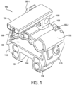
- the profile and/or outer periphery of guide 100 defined by inferior side 104, superior side 106, and opposed sides 108, 110 may correspond to the tibial and/or talar prosthesis components of a total ankle replacement system, although one of ordinary skill in the art will understand that body 102 of guide 100 may have a shape that corresponds to other types of implants.
- body 102 may be formed from a rigid radiopaque material, such as a surgical grade metal.
- a rigid radiopaque material such as a surgical grade metal.
- guide 100 may be formed from other materials, such as a combination of radiolucent (e.g., Radel ® polyphenylsulfone (PPSU), available from Solvay) and radiopaque (e.g., stainless steel, aluminum, titanium, cobalt, chromium) materials.
- Guide 100 may be machined from a single block of material, molded, or formed using an additive manufacturing process (e.g., Direct Metal Laser Sintered (DMLS), Electron Beam Melting (EBM)).
- DMLS Direct Metal Laser Sintered
- EBM Electron Beam Melting
- the inferior side 104 may include a pair of spaced apart legs 116, 118 that extend inferiorly from body 102.
- a gap 120 is defined between the legs 116, 118 and inferior side 104.
- Gap 120 is shown as having a generally rectangular shaped in which its length (e.g., space between legs 116, 118) is greater than its width (e.g., length of legs 116, 118), but it should be understood that gap 120 may have a square shape in which the length and width dimensions are equal. Further, one of ordinary skill in the art will understand that gap 120 may have other shapes (e.g., arced, triangular, etc.) to facilitate visualization of the underlying bone.
- a crossbar may extend across gap 120, i.e., from leg 116 to leg 118.
- the crossbar may have a surface (e.g., a lower or inferior surface) that corresponds to a location of a potential resection line (e.g., the location at which a planar surface of a talus is formed) as will be described in greater detail below.
- holes 122, 124, 126, 128 may be sized and configured to receive an engagement feature for coupling an alignment guide, such as an angel wing alignment guide 200 described below and illustrated in FIGS. 8-14 , to the guide 100, although one of ordinary skill in the art will understand that other guides or surgical device may be coupled to guide 100 via one or more holes 122, 124, 126, 128.
- an alignment guide such as an angel wing alignment guide 200 described below and illustrated in FIGS. 8-14
- other guides or surgical device may be coupled to guide 100 via one or more holes 122, 124, 126, 128.
- the features could be reversed, where the angel wing alignment guide 200 possess holes 122, 126 and guide 100 defines projections 210-1, 210-2.
- one of more of holes 122, 124, 126, 128 may be oblong or take the form of slots to facilitate proper alignment and coupling of other tools and guides.
- holes 126, 128 are shown having an oblong shape, and it should be appreciated that one or more of the other holes 122, 124, 126, 128 or combinations of holes may have other forms and shapes.
- guide 100 may include one or more alignment features, including one or more alignment features that extend superiorly from superior side 106.
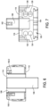
- a first alignment feature which may be a sagittal alignment feature, may extend from superior side 106 and include at least a first component 150-1 and a second component 150-2.
- the first component 150-1 takes the form of a block having a circular opening 152 ( FIG. 5 )
- second component 150-2 takes the form of a projection that terminates in a circular shape 154 ( FIG. 4 ). As best seen in FIGS.
- guide 100 may include a second alignment feature, which may be a coronal alignment feature and may also extend from superior side 106.
- Second alignment feature includes a base 156 and a flange 158 that extends in an anterior direction from base 156.
- Base 156 defines a hole 160 that extends entirely through base 156, as best seen in FIG. 3 .
- Flange 158 extends from base 156 in an anterior direction and includes a projection 162 along its length.
- flange 158 has a trapezoidal cross-sectional geometry that is sized and configured to form a dovetail connection with another surgical tool, such as the adjustment block 300 with a tool holder 330 disclosed in U.S. Patent No. 10,136,904 , which was incorporated by reference in its entirety above.
- flange 158 may have other cross-sectional geometries to facilitate coupling to other surgical tools.
- projection 162 extends from flange 158 in an inferior direction and terminates with a circular shape.
- projection 162 will appear to be disposed within the center of hole 160 (e.g., a bullseye) to provide a fluoroscopic alignment check.
- hole 160 and projection 162 are described and shown as having circular shapes, one of ordinary skill in the art will understand that hole 160 and projection 162 may have other shapes.
- first and second alignment features are described as extending from superior side 106 of guide 100, it should be understood that the first and/or second alignment features may be otherwise located on guide 100.
- one or both of the first and second alignment features may extend from other sides or surfaces of the guide, such as the anterior side 112, the inferior side 104 or may be otherwise incorporated into the body 102 of guide 100.
- the first and/or second alignment features may be positioned on another guide that may be coupled to guide 100.
- the first, second, and/or additional alignment features could be disposed on or otherwise provided by the angel wing alignment guide 200, which is described in greater detail below.
- the posterior side 114 may be angled or include a beveled surface 166.
- Beveled surface 166 may extend away from posterior side 114 in an anterior direction to provide clearance for the talus when guide 100 is positioned against a tibia.
- posterior side 114 may include a notch or slot 168 that extends inwardly (e.g., in an anterior direction). Notch 168 is aligned with the surface of superior side 106 and provides a visual indicator as to the upper surface of a prosthesis (not shown) that corresponds to guide 100.
- guide 100 may be provided in one or more sizes, which corresponding to one or more sizes of available implants, such as a tibial implant of a total ankle prosthesis.
- notch 168 provides the surgeon with an indication as to where the tibia will be resected and where the upper (e.g., superior) surface of the tibial component of the ankle prosthesis will be located.
- One or more additional notches may be provided along the posterior side 114 to identify the location of the lower (e.g., inferior) surface of the tibial component or talar component or upper (e.g., superior) surface of the talar component, as will be understood by one of ordinary skill in the art.
- notch 168 is shown being located along the posterior side 114 so that the notch is positioned adjacent to bone, other types of visual indicators may be used and placed at other locations on body 102 of guide 100.
- legs 116, 118 may include one or more steps, such as steps 170-1, 170-2, 172-1, 172-2, for providing a surgeon with a visual indication as to the location of a lower or upper surface of a prosthesis (e.g., a talar prosthesis).
- steps 170-1, 170-2, 172-1, 172-2 may be provided, including sizes having multiple heights, e.g., short and tall heights.
- steps 170-1, 170-2 may correspond to a short or chamfer sized implant
- steps 172-1, 172-2 collectively, “steps 172”
- a respective surface of steps 170 may be coplanar with the inferior surface 104
- steps 172 may be coplanar with a crossbar (not shown) that extends between legs 116, 116, if provided.
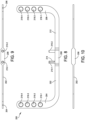
- Alignment guide 200 may have a generally arcuate or "u-shaped" body with a transverse beam 202 extending between a first arm 204 and a second arm 206.
- the transverse beam 202 may include an enlarged area 208, which may have a width that is greater than a width of a remainder of the transverse beam 202 and/or a width of arms 204, 206.
- arm 204 includes one or more holes 216-1, 216-2, 216-3, 216-4 (collectively, “holes 216"), and arm 206 includes one or more holes 218-1, 218-2, 218-3, 218-4 (collectively, “holes 218").
- Holes 216, 218 are sized and configured to receive a dowel, pin, rod, or other elongate radiopaque device.
- the elongate radiopaque device may be coupled to the alignment guide 200 to provide a surgeon with an approximation of an axis of a tibial implant that is to be implant such that the surgeon can assess the proper location of a cutting and/or reaming guide with a mechanical and/or anatomic axis of the patient.
- FIG. 8 Although plural holes are shown in FIG. 8 to provide the surgeon with multiple locations at which the alignment rod may be positioned, it should be understood that a single hole may be provided, or one or more slots may be provided along the longitudinal axes of the arms 204, 206 to provide the surgeon with the ability to provide near continuous adjustment of the location of such an alignment rod.
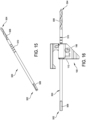
- Drill bit 500 extends from a first end 502, which may also be referred to as a "coupling end” or a “trailing end,” to a second end 504, which may also be referred to as a “drilling end” or a “leading end.”
- Coupling end 502 may include one or more flats 506 or other surfaces that facilitate engagement with a power system or hand tool as will be understood by one of ordinary skill in the art.
- Leading end 504 may include one or more threads or cutting elements 508 to facilitate a drilling operation.
- Drill bit 500 may further include one or more grooves or other indicia 510 disposed along a length of the drill bit 500.
- indicia 510 may include numerals and/or letters in addition to grooves, as will be understood by one of ordinary skill in the art.
- the one or more indicia 510 is located between an approximate middle of drill bit 500 and a proximal end of cutting element(s) 508.
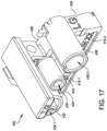
- the posterior side 414 may include one or more notches 418, which are aligned with slots 416, and one or more notches 438, which are aligned with the superior surface 406 of body 402.
- the one or more notches 418 provide a surgeon or other medical professional with a visual indication as to the location of the slots 416, which may correspond to the location of a bone resection and/or an inferior surface of an implant based on the positioning of the guide 400 when guide 400 is viewed under fluoroscopy in the sagittal plane.
- the one or more notches 438 may provide a surgeon or other medical professional with a visual indication as to the location of the superior surface of the body 402, which may correspond to a superior surface of an implant, such as the tibial implant of a total ankle prosthesis.
- Body 402 may also define a central opening 420 located between inferior side 404 and superior side 406 and between opposed sides 408, 410.
- one or more projections 422-1, 422-2 which collectively may be referred to as “projections 422" or “joint-line indicator 422,” extend inwardly into opening 420.
- Projections 422 are located along body 402 to provide a surgeon or other medical professional a visual indication as to the location of the joint line of a prosthesis, such as a total ankle prosthesis, that is to be implanted when viewed in the frontal plane. While projections 422 are shown as being pointed or arrow shaped, one of ordinary skill in the art will understand that the projections 422 may take other shapes and forms to provide a joint line indicator 422.
- a number of holes may be provided adjacent to the superior side 406 of body 402 above opening 420.
- body 402 may define corner drill holes 428-1, 428-2 (collectively, “holes 428" or “corner drill holes 428”) and a central hole 430.
- Corner drill holes 428 may be sized and configured to receive a drill bit and/or to identify a location of where a drill is used to prepare the corners of a tibial resection. Put another way, the corner drill holes 428 are located at the superior medial and lateral corners of the tibial resection.
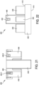
- the circular shape 444 when viewed from the side and the fluoroscope is properly aligned with the guide 400, the circular shape 444 will appear within an approximate center of the circular opening 442 defined by the first component 440-1 to form a fluoroscopic check (e.g., a bullseye). If the fluoroscope is not properly aligned, then the circular shape 444 will not appear centered within circular opening 442.
- a fluoroscopic check e.g., a bullseye
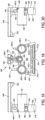
- Second alignment feature may include a base 446 and a flange 448 that extends in an anterior direction from base 446.
- Base 446 defines a hole 450 that extends entirely through base 446, as best seen in FIG. 18 .
- Flange 448 extends from base 446 in an anterior direction and includes a projection 452 along its length.
- flange 448 has a trapezoidal cross-sectional geometry that is sized and configured to form a dovetail connection with another surgical tool, such as the adjustment block 300 with a tool holder 330 disclosed in U.S. Patent No. 10,136,904 , which was incorporated by reference in its entirety above.
- flange 448 may have other cross-sectional geometries to facilitate coupling to other surgical tools.
- projection 452 extends from flange 448 in an inferior direction and terminates with a circular shape.
- hole 450 e.g., a bullseye
- hole 450 and projection 452 are described and shown as having circular shapes, one of ordinary skill in the art will understand that hole 450 and projection 452 may have other shapes.
- base 446 may be located closer to or at the anterior side 412 of body 402.
- base 446 may define a second hole 454 that is aligned with circular opening 442 defined by first component 440-1 of the first alignment feature such that second component 440-2 may be visible through both circular opening 442 and hole 454, as best seen in FIG. 20 .
- hole 454 may be omitted depending on the relative positioning of the first alignment feature and base 446.
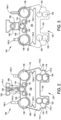
- the position of guide 100 may be adjusted in order to assess the sizing and/or alignment of guide 100 relative to the tibia TB and/or talus TS.
- profile of the guide such as provided by the inferior side 104, superior side 106, and opposed sides 108, 110, which may correspond to a profile of a tibial implant, may be used to assess whether the size of the corresponding implant is appropriate for the patient in the frontal plane and/or sagittal plane.
- Sizing of the implant in the sagittal plane may be performed by a surgeon or other medical professional with the assistance of one or more notches 168 and/or alignment guide 200, which may be located on guide 100 such that they correspond to the superior side 106 and/or inferior side 104.
- Such assessment may be performed using fluoroscopy.
- one or more of the first and second alignment features may be used to ensure proper alignment of the fluoroscope and guide 100.
- a guide 200 may be coupled to the guide 100 while determining the size and/or alignment of an implant.
- one or more protrusions 210 may be inserted into holes 122, 126 or holes 124, 128 defined by legs 116, 118 to couple alignment guide 200 to guide 100, as shown in FIGS. 11-14 .
- a surface e.g., a bottom or top surface
- steps 170 when protrusions 210 of alignment guide 200 are disposed within holes 124, 128 of guide 100.
- the surface(s) of arms 204, 206 may provide a visual indication of a location of an inferior surface of an implant (e.g., a talar implant) and/or a location at which a talus will be resected.
- an elongate radiopaque device may be inserted into one or more of the holes or slots 216, 218 defined by the arms 204, 206 of guide 200 to assess the alignment of guide 100 with an axis of the tibia TB (e.g., a mechanical and/or anatomic axis).
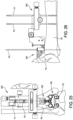
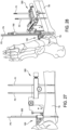
- guide 100 may be secured to the tibia TB by placing one or more pins P3, P4 in holes 140, 142, as shown in FIGS. 26-28 .
- drill bit 500 may be advanced into the tibia TB guided by hole 144, as illustrated in FIG. 27 .
- Drill bit 500 may be advanced until it reaches the posterior surface of tibia TB.
- the location of the drill bit 500 may be determined using fluoroscopy as will be understood by one of ordinary skill in the art.
- the length of the implant (e.g., anterior-to-posterior dimension) may be determined based on the visible indicia 510 located along the length of drill bit 500.
- guide 100 is used to drill the corners for the tibial resection.
- a drill 700 may be inserted into corner drill holes 136, 138 and into the tibia TB, as shown in FIG. 28 .
- guide 100 may be removed from its engagement with the tibia TB and/or adjustment block 300.
- the tibia and talus may be further prepared using any suitable surgical technique, including the technique disclosed in U.S. Patent No. 10,136,904 , which was incorporated by reference above.
- a surgical guide includes a body having a shape that corresponds to a shape of an implant to be implanted.
- the body defines a first opening and at least one hole that is sized and configured to receive a tool therein.
- a first alignment feature is configured to facilitate alignment of the surgical guide with a first anatomic plane.
- the body includes a first side, a second side, a third side, and a fourth side, and the first opening is defined by the first side, the second side, the third side, and the fourth side.
- connection feature includes a dowel
- At least one of the first and second legs includes at least one step.
- the at least one step may provide a visual indication as to a location of a surface of a prosthesis to be implanted.
- the first and second legs include a plurality of steps.
- the first and second legs include a beveled surface.
- the first anatomic plane is a sagittal plane
- the second anatomic plane is a frontal plane
- the first alignment feature includes a first component and a second component.
- the first component may include an opening
- the second component may include a projection that terminates in a shape that is complementary to a shape of the opening.
- the opening is defined by a block.
- the projection terminates from a flange that has a cross-sectional geometry to facilitate the coupling of the surgical guide to another surgical tool.
- the cross-sectional geometry is trapezoidal.
- the body defines at least one slot that is disposed between the opening and the second side.
- the at least one slot may be sized and configured to receive a tool, including a depth indicating tool or a blade of a cutting tool.
- the body includes a joint line indicator.
- the joint line indicator includes at least one projection extending into the opening defined by the body.
- the joint line indicator includes a notch formed in at least one of a posterior side and/or an anterior side of the body.
- the system includes a second guide.
- the second guide may have a transverse beam that extends between a first arm and a second arm.
- the second guide may be configured to be coupled to the first guide.
- each of the first and second arms of the second guide define at least one connection feature for receiving an elongate radiopaque device therein.
- the at least one connection feature includes a hole.
- the at least one connection feature includes a slot.
- the system includes a drill bit that extends from a first end to a second end.
- the first end may be configured to be coupled to a driving tool, and the second end may include at least one cutting surface.
- the drill bit may include at least one indicia located along its length at a distance from the second end. The distance of the at least one indicia from the second end may correspond to a length of an implant.
- the drill bit may be sized and configured to be received in a third hole defined by the first guide body.
- the third hole defined by the first guide body is located between the first hole and the second hole.
- the at least one indicia includes a plurality of indicia.
- Each indicia of the plurality of indicia may be disposed at a respective distance from the second end of the drill bit. The respective distance may correspond to a respective length of a different implant.
- a method includes coupling a first guide to an adjustment block, aligning a fluoroscope with the first guide in at least one anatomic plane using at least one of a first alignment feature and a second alignment feature of the first guide, coupling a second guide, and securing the first guide to a tibia once a desired alignment of the first guide has been achieved.
- the second guide includes first and second arms that are coupled together by a transverse beam.
- coupling the second guide to the first guide includes inserting at least one protrusion extending from the transverse beam of the second guide into at least one connection feature of the first guide.
- the at least one connection feature of the first guide includes at least one hole defined by the first guide.
- the at least one connection feature of the first guide includes at least one slot defined by the first guide.
- determining the size of the implant includes inserting a drill bit into a hole defined by the first guide and into the tibia, and identifying an indicia disposed along a length of the drill bit.
- a method includes preparing a tibia for resection by inserting a drill into a first corner drill hole defined by the first guide.
- a method includes inserting the drill into a second corner drill hole defined by the first guide.
Landscapes
- Health & Medical Sciences (AREA)
- Surgery (AREA)
- Life Sciences & Earth Sciences (AREA)
- Heart & Thoracic Surgery (AREA)
- Molecular Biology (AREA)
- Oral & Maxillofacial Surgery (AREA)
- Engineering & Computer Science (AREA)
- Biomedical Technology (AREA)
- Dentistry (AREA)
- Medical Informatics (AREA)
- Nuclear Medicine, Radiotherapy & Molecular Imaging (AREA)
- Animal Behavior & Ethology (AREA)
- General Health & Medical Sciences (AREA)
- Public Health (AREA)
- Veterinary Medicine (AREA)
- Orthopedic Medicine & Surgery (AREA)
- Surgical Instruments (AREA)
- Prostheses (AREA)
Claims (9)
- Chirurgische Führung (100), umfassend:einen Körper (102), der eine Form aufweist, die mit der Form eines zu implantierenden Implantats korrespondiert, wobei der Körper (102) eine erste Öffnung (130) und mindestens ein Loch (136, 138, 144) definiert, das bemessen und konfiguriert ist, um ein Instrument darin aufzunehmen, undein erstes Ausrichtungsmerkmal (150-1, 150-2), das mit mindestens einer Seite des Körpers (102) gekoppelt und konfiguriert ist, um die Ausrichtung der chirurgischen Führung (100) mit einer ersten anatomischen Ebene zu ermöglichen, undwobei das erste Ausrichtungsmerkmal (150-1, 150-2) eine erste Komponente (150-1) und eine zweite Komponente (150-2) aufweist, wobei die erste Komponente eine zweite Öffnung (152) aufweist und die zweite Komponente (150-2) einen Vorsprung aufweist, der in einer Form (154) endet, die komplementär zu einer Form der zweiten Öffnung ist.
- Chirurgische Führung (100) nach Anspruch 1, ferner umfassend ein zweites Ausrichtungsmerkmal (156, 158), das mit dem Körper (102) gekoppelt und konfiguriert ist, um die Ausrichtung der chirurgischen Führung (100) mit einer zweiten anatomischen Ebene zu ermöglichen, die sich von der ersten anatomischen Ebene unterscheidet, und wobei der Körper (102) eine erste Seite (104), eine zweite Seite (106), eine dritte Seite (108) und eine vierte Seite (110) aufweist, und wobei sich das erste Ausrichtungsmerkmal (150-1, 150-2) von der zweiten Seite (106) des Körpers (102) erstreckt.
- Chirurgische Führung (100) nach Anspruch 2, wobei sich das zweite Ausrichtungsmerkmal (156, 158) von der zweiten Seite (106) des Körpers (102) erstreckt.
- Chirurgische Führung (100) nach Anspruch 2, wobei sich ein erster und ein zweiter Schenkel (116, 118) von der ersten Seite (104) des Körpers (102) erstrecken, wobei jeder des ersten und des zweiten Schenkels ein jeweiliges Loch (122, 124, 126, 128) definiert, das bemessen und konfiguriert ist, um ein Verbindungsmerkmal einer anderen chirurgischen Führung (100) aufzunehmen.
- Chirurgische Führung (100) nach Anspruch 4, wobei der erste und der zweite Schenkel (116, 118) eine abgeschrägte Oberfläche aufweisen oder wobei mindestens einer des ersten und des zweiten Schenkels (116, 118) mindestens eine Stufe aufweist, wobei die mindestens eine Stufe eine visuelle Anzeige hinsichtlich der Position einer Oberfläche einer zu implantierenden Prothese bereitstellt, wobei der erste und der zweite Schenkel (116, 118) eine Vielzahl von Stufen aufweisen.
- Chirurgische Führung (100) nach einem der vorstehenden Ansprüche, wobei die erste anatomische Ebene eine Sagittalebene ist oder wobei die erste anatomische Ebene eine Frontalebene ist.
- Chirurgische Führung (100) nach einem der Ansprüche 1 bis 6, wobei sich der Vorsprung an einem Abschlussende eines Flansches befindet, der eine Querschnittsgeometrie aufweist, um die Kopplung der chirurgischen Führung (100) an ein anderes chirurgisches Instrument zu ermöglichen.
- Chirurgische Führung (100) nach einem der vorstehenden Ansprüche, wobei das mindestens eine Loch (136, 138, 144) ein erstes Loch (136), ein zweites Loch (138) und ein drittes Loch (144) aufweist, das zwischen dem ersten Loch (136) und dem zweiten Loch (138) eingerichtet ist, wobei typischerweise das erste Loch (146) durch eine erste Buchse definiert ist, die sich von dem Körper (102) erstreckt, das zweite Loch (138) durch eine zweite Buchse definiert ist, die sich von dem Körper (102) erstreckt, und das dritte Loch (144) durch eine dritte Buchse definiert ist, die sich von dem Körper (102) erstreckt.
- Chirurgische Führung (100) nach einem der vorstehenden Ansprüche, wobei der Körper (102) mindestens einen Schlitz definiert, der bemessen und konfiguriert ist, um mindestens eines von einem Tiefenanzeigeinstrument oder einer Klinge eines Schneidinstruments aufzunehmen, und/oder wobei mindestens eines von einer Rückseite oder einer Vorderseite des Körpers (102) eine Kerbe aufweist, die konfiguriert ist, um eine visuelle Anzeige einer Position von mindestens einer Oberfläche einer zu implantierenden Prothese bereitzustellen, wenn die chirurgische Führung (100) in einer Sagittalebene betrachtet wird, und/oder wobei der Körper (102) einen Gelenklinienindikator aufweist, wobei der Gelenklinienindikator mindestens einen Vorsprung umfasst, der sich in die erste Öffnung (130) erstreckt, die durch den Körper (102) definiert ist, wobei typischerweise der Gelenklinienindikator eine Kerbe aufweist, die in mindestens einer von einer Rückseite oder einer Vorderseite des Körpers (102) ausgebildet ist.
Applications Claiming Priority (2)
| Application Number | Priority Date | Filing Date | Title |
|---|---|---|---|
| US202263268615P | 2022-02-28 | 2022-02-28 | |
| US18/054,948 US20230270456A1 (en) | 2022-02-28 | 2022-11-14 | Surgical guides and methods of using the same |
Publications (2)
| Publication Number | Publication Date |
|---|---|
| EP4265201A1 EP4265201A1 (de) | 2023-10-25 |
| EP4265201B1 true EP4265201B1 (de) | 2025-04-09 |
Family
ID=84358811
Family Applications (1)
| Application Number | Title | Priority Date | Filing Date |
|---|---|---|---|
| EP22208047.5A Active EP4265201B1 (de) | 2022-02-28 | 2022-11-17 | Chirurgische führungen |
Country Status (1)
| Country | Link |
|---|---|
| EP (1) | EP4265201B1 (de) |
Family Cites Families (6)
| Publication number | Priority date | Publication date | Assignee | Title |
|---|---|---|---|---|
| US10105151B2 (en) * | 2012-12-12 | 2018-10-23 | Wright Medical Technology, Inc. | Instrument for intra-operative implant templating using fluoroscopy |
| US9480571B2 (en) | 2012-12-27 | 2016-11-01 | Wright Medical Technology, Inc. | Ankle replacement system and method |
| US9974588B2 (en) | 2012-12-27 | 2018-05-22 | Wright Medical Technology, Inc. | Ankle replacement system and method |
| AU2019263150B2 (en) * | 2018-04-30 | 2023-09-14 | Paragon 28, Inc. | Laser-based implant alignment and resection guide systems and related methods |
| CA3122564A1 (en) * | 2018-12-13 | 2020-06-18 | Paragon 28, Inc. | Resection guides, sweeping reamers, and methods for use in total ankle replacement |
| US12349926B2 (en) * | 2020-03-11 | 2025-07-08 | Stryker European Operations Limited | Patient-specific ankle guide systems and methods |
-
2022
- 2022-11-17 EP EP22208047.5A patent/EP4265201B1/de active Active
Also Published As
| Publication number | Publication date |
|---|---|
| EP4265201A1 (de) | 2023-10-25 |
Similar Documents
| Publication | Publication Date | Title |
|---|---|---|
| US12156664B2 (en) | Resection guides, sweeping reamers, and methods for use in total ankle replacement | |
| US9968376B2 (en) | Patient-specific orthopedic instruments | |
| US9700329B2 (en) | Patient-specific orthopedic instruments | |
| JP6258265B2 (ja) | 人工膝関節形成術を実施するための方法及び装置 | |
| US9308006B2 (en) | Instruments for total knee arthroplasty | |
| EP2623045B1 (de) | Operationsinstrumentensatz | |
| US6056754A (en) | Method and apparatus for patella resection and guide handle | |
| US20190262005A1 (en) | Patient-matched instrumentation and methods | |
| EP2623044B1 (de) | Chirurgischer Schnittblock | |
| CN107343808B (zh) | 基于x光照片的切削模定位夹具 | |
| EP1393696A1 (de) | Schneideführungsbefestigung und Verfahren zur Sprunggelenkfixierung | |
| EP2501302B1 (de) | Bohrführung | |
| MX2013007207A (es) | Guia de cirugia ortopedica. | |
| GB2531215A (en) | Patient-specific partial knee guides | |
| CA2845351C (en) | Cutting guide for generating an outer contour for a joint endoprosthesis | |
| US20230270456A1 (en) | Surgical guides and methods of using the same | |
| JP2004537368A (ja) | 大腿骨切除平面の位置を定めるガイド | |
| EP4265201B1 (de) | Chirurgische führungen | |
| US20250345070A1 (en) | Chamfer guidance systems and methods | |
| US20230346394A1 (en) | Combination femoral preparation cutting blocks for knee arthroplasty | |
| EP4091554A2 (de) | Multimodale patientenspezifische chirurgische führungen | |
| WO2025202027A1 (en) | Kinematically aligned orthopaedic surgical instrument and method of using the same in an orthopaedic knee procedure | |
| AU2015264937B2 (en) | Patient-matched instrumentation and methods |
Legal Events
| Date | Code | Title | Description |
|---|---|---|---|
| REG | Reference to a national code |
Ref country code: DE Ref legal event code: R138 Ref document number: 202022003186 Country of ref document: DE Free format text: GERMAN DOCUMENT NUMBER IS 602022012855 |
|
| PUAI | Public reference made under article 153(3) epc to a published international application that has entered the european phase |
Free format text: ORIGINAL CODE: 0009012 |
|
| STAA | Information on the status of an ep patent application or granted ep patent |
Free format text: STATUS: REQUEST FOR EXAMINATION WAS MADE |
|
| 17P | Request for examination filed |
Effective date: 20221117 |
|
| AK | Designated contracting states |
Kind code of ref document: A1 Designated state(s): AL AT BE BG CH CY CZ DE DK EE ES FI FR GB GR HR HU IE IS IT LI LT LU LV MC ME MK MT NL NO PL PT RO RS SE SI SK SM TR |
|
| RBV | Designated contracting states (corrected) |
Designated state(s): AL AT BE BG CH CY CZ DE DK EE ES FI FR GB GR HR HU IE IS IT LI LT LU LV MC ME MK MT NL NO PL PT RO RS SE SI SK SM TR |
|
| GRAP | Despatch of communication of intention to grant a patent |
Free format text: ORIGINAL CODE: EPIDOSNIGR1 |
|
| STAA | Information on the status of an ep patent application or granted ep patent |
Free format text: STATUS: GRANT OF PATENT IS INTENDED |
|
| RIC1 | Information provided on ipc code assigned before grant |
Ipc: A61B 17/00 20060101ALN20241105BHEP Ipc: A61B 90/00 20160101ALN20241105BHEP Ipc: A61B 17/17 20060101ALI20241105BHEP Ipc: A61B 17/15 20060101AFI20241105BHEP |
|
| INTG | Intention to grant announced |
Effective date: 20241115 |
|
| GRAS | Grant fee paid |
Free format text: ORIGINAL CODE: EPIDOSNIGR3 |
|
| GRAA | (expected) grant |
Free format text: ORIGINAL CODE: 0009210 |
|
| STAA | Information on the status of an ep patent application or granted ep patent |
Free format text: STATUS: THE PATENT HAS BEEN GRANTED |
|
| AK | Designated contracting states |
Kind code of ref document: B1 Designated state(s): AL AT BE BG CH CY CZ DE DK EE ES FI FR GB GR HR HU IE IS IT LI LT LU LV MC ME MK MT NL NO PL PT RO RS SE SI SK SM TR |
|
| P01 | Opt-out of the competence of the unified patent court (upc) registered |
Free format text: CASE NUMBER: APP_10027/2025 Effective date: 20250227 |
|
| REG | Reference to a national code |
Ref country code: GB Ref legal event code: FG4D |
|
| REG | Reference to a national code |
Ref country code: CH Ref legal event code: EP |
|
| REG | Reference to a national code |
Ref country code: DE Ref legal event code: R096 Ref document number: 602022012855 Country of ref document: DE |
|
| REG | Reference to a national code |
Ref country code: IE Ref legal event code: FG4D |
|
| PG25 | Lapsed in a contracting state [announced via postgrant information from national office to epo] |
Ref country code: NL Free format text: LAPSE BECAUSE OF FAILURE TO SUBMIT A TRANSLATION OF THE DESCRIPTION OR TO PAY THE FEE WITHIN THE PRESCRIBED TIME-LIMIT Effective date: 20250409 |
|
| REG | Reference to a national code |
Ref country code: AT Ref legal event code: MK05 Ref document number: 1782808 Country of ref document: AT Kind code of ref document: T Effective date: 20250409 |
|
| PG25 | Lapsed in a contracting state [announced via postgrant information from national office to epo] |
Ref country code: FI Free format text: LAPSE BECAUSE OF FAILURE TO SUBMIT A TRANSLATION OF THE DESCRIPTION OR TO PAY THE FEE WITHIN THE PRESCRIBED TIME-LIMIT Effective date: 20250409 Ref country code: PT Free format text: LAPSE BECAUSE OF FAILURE TO SUBMIT A TRANSLATION OF THE DESCRIPTION OR TO PAY THE FEE WITHIN THE PRESCRIBED TIME-LIMIT Effective date: 20250811 Ref country code: ES Free format text: LAPSE BECAUSE OF FAILURE TO SUBMIT A TRANSLATION OF THE DESCRIPTION OR TO PAY THE FEE WITHIN THE PRESCRIBED TIME-LIMIT Effective date: 20250409 |
|
| REG | Reference to a national code |
Ref country code: LT Ref legal event code: MG9D |
|
| PG25 | Lapsed in a contracting state [announced via postgrant information from national office to epo] |
Ref country code: GR Free format text: LAPSE BECAUSE OF FAILURE TO SUBMIT A TRANSLATION OF THE DESCRIPTION OR TO PAY THE FEE WITHIN THE PRESCRIBED TIME-LIMIT Effective date: 20250710 Ref country code: NO Free format text: LAPSE BECAUSE OF FAILURE TO SUBMIT A TRANSLATION OF THE DESCRIPTION OR TO PAY THE FEE WITHIN THE PRESCRIBED TIME-LIMIT Effective date: 20250709 |
|
| PG25 | Lapsed in a contracting state [announced via postgrant information from national office to epo] |
Ref country code: PL Free format text: LAPSE BECAUSE OF FAILURE TO SUBMIT A TRANSLATION OF THE DESCRIPTION OR TO PAY THE FEE WITHIN THE PRESCRIBED TIME-LIMIT Effective date: 20250409 |
|
| PG25 | Lapsed in a contracting state [announced via postgrant information from national office to epo] |
Ref country code: BG Free format text: LAPSE BECAUSE OF FAILURE TO SUBMIT A TRANSLATION OF THE DESCRIPTION OR TO PAY THE FEE WITHIN THE PRESCRIBED TIME-LIMIT Effective date: 20250409 |
|
| PG25 | Lapsed in a contracting state [announced via postgrant information from national office to epo] |
Ref country code: HR Free format text: LAPSE BECAUSE OF FAILURE TO SUBMIT A TRANSLATION OF THE DESCRIPTION OR TO PAY THE FEE WITHIN THE PRESCRIBED TIME-LIMIT Effective date: 20250409 |
|
| PG25 | Lapsed in a contracting state [announced via postgrant information from national office to epo] |
Ref country code: AT Free format text: LAPSE BECAUSE OF FAILURE TO SUBMIT A TRANSLATION OF THE DESCRIPTION OR TO PAY THE FEE WITHIN THE PRESCRIBED TIME-LIMIT Effective date: 20250409 |
|
| PGFP | Annual fee paid to national office [announced via postgrant information from national office to epo] |
Ref country code: FR Payment date: 20250908 Year of fee payment: 4 |
|
| PG25 | Lapsed in a contracting state [announced via postgrant information from national office to epo] |
Ref country code: RS Free format text: LAPSE BECAUSE OF FAILURE TO SUBMIT A TRANSLATION OF THE DESCRIPTION OR TO PAY THE FEE WITHIN THE PRESCRIBED TIME-LIMIT Effective date: 20250709 |
|
| PG25 | Lapsed in a contracting state [announced via postgrant information from national office to epo] |
Ref country code: IS Free format text: LAPSE BECAUSE OF FAILURE TO SUBMIT A TRANSLATION OF THE DESCRIPTION OR TO PAY THE FEE WITHIN THE PRESCRIBED TIME-LIMIT Effective date: 20250809 |
|
| PG25 | Lapsed in a contracting state [announced via postgrant information from national office to epo] |
Ref country code: LV Free format text: LAPSE BECAUSE OF FAILURE TO SUBMIT A TRANSLATION OF THE DESCRIPTION OR TO PAY THE FEE WITHIN THE PRESCRIBED TIME-LIMIT Effective date: 20250409 |
|
| REG | Reference to a national code |
Ref country code: CH Ref legal event code: U11 Free format text: ST27 STATUS EVENT CODE: U-0-0-U10-U11 (AS PROVIDED BY THE NATIONAL OFFICE) Effective date: 20251201 |
|
| PGFP | Annual fee paid to national office [announced via postgrant information from national office to epo] |
Ref country code: DE Payment date: 20250923 Year of fee payment: 4 |
|
| PG25 | Lapsed in a contracting state [announced via postgrant information from national office to epo] |
Ref country code: DK Free format text: LAPSE BECAUSE OF FAILURE TO SUBMIT A TRANSLATION OF THE DESCRIPTION OR TO PAY THE FEE WITHIN THE PRESCRIBED TIME-LIMIT Effective date: 20250409 Ref country code: SM Free format text: LAPSE BECAUSE OF FAILURE TO SUBMIT A TRANSLATION OF THE DESCRIPTION OR TO PAY THE FEE WITHIN THE PRESCRIBED TIME-LIMIT Effective date: 20250409 |
|
| PGFP | Annual fee paid to national office [announced via postgrant information from national office to epo] |
Ref country code: CH Payment date: 20251201 Year of fee payment: 4 |
|
| PG25 | Lapsed in a contracting state [announced via postgrant information from national office to epo] |
Ref country code: CZ Free format text: LAPSE BECAUSE OF FAILURE TO SUBMIT A TRANSLATION OF THE DESCRIPTION OR TO PAY THE FEE WITHIN THE PRESCRIBED TIME-LIMIT Effective date: 20250409 |
|
| PG25 | Lapsed in a contracting state [announced via postgrant information from national office to epo] |
Ref country code: EE Free format text: LAPSE BECAUSE OF FAILURE TO SUBMIT A TRANSLATION OF THE DESCRIPTION OR TO PAY THE FEE WITHIN THE PRESCRIBED TIME-LIMIT Effective date: 20250409 |
|
| PG25 | Lapsed in a contracting state [announced via postgrant information from national office to epo] |
Ref country code: SK Free format text: LAPSE BECAUSE OF FAILURE TO SUBMIT A TRANSLATION OF THE DESCRIPTION OR TO PAY THE FEE WITHIN THE PRESCRIBED TIME-LIMIT Effective date: 20250409 |
|
| PG25 | Lapsed in a contracting state [announced via postgrant information from national office to epo] |
Ref country code: IT Free format text: LAPSE BECAUSE OF FAILURE TO SUBMIT A TRANSLATION OF THE DESCRIPTION OR TO PAY THE FEE WITHIN THE PRESCRIBED TIME-LIMIT Effective date: 20250409 |
|
| PLBE | No opposition filed within time limit |
Free format text: ORIGINAL CODE: 0009261 |
|
| STAA | Information on the status of an ep patent application or granted ep patent |
Free format text: STATUS: NO OPPOSITION FILED WITHIN TIME LIMIT |