EP4265016B1 - Ultrabreitbandige messungen zur funkzugangstechnologieunabhängigen positionierung - Google Patents
Ultrabreitbandige messungen zur funkzugangstechnologieunabhängigen positionierung Download PDFInfo
- Publication number
- EP4265016B1 EP4265016B1 EP21836241.6A EP21836241A EP4265016B1 EP 4265016 B1 EP4265016 B1 EP 4265016B1 EP 21836241 A EP21836241 A EP 21836241A EP 4265016 B1 EP4265016 B1 EP 4265016B1
- Authority
- EP
- European Patent Office
- Prior art keywords
- uwb
- positioning
- location
- information
- location server
- Prior art date
- Legal status (The legal status is an assumption and is not a legal conclusion. Google has not performed a legal analysis and makes no representation as to the accuracy of the status listed.)
- Active
Links
Images


Classifications
-
- G—PHYSICS
- G01—MEASURING; TESTING
- G01S—RADIO DIRECTION-FINDING; RADIO NAVIGATION; DETERMINING DISTANCE OR VELOCITY BY USE OF RADIO WAVES; LOCATING OR PRESENCE-DETECTING BY USE OF THE REFLECTION OR RERADIATION OF RADIO WAVES; ANALOGOUS ARRANGEMENTS USING OTHER WAVES
- G01S5/00—Position-fixing by co-ordinating two or more direction or position line determinations; Position-fixing by co-ordinating two or more distance determinations
- G01S5/02—Position-fixing by co-ordinating two or more direction or position line determinations; Position-fixing by co-ordinating two or more distance determinations using radio waves
- G01S5/0205—Details
- G01S5/0236—Assistance data, e.g. base station almanac
-
- H—ELECTRICITY
- H04—ELECTRIC COMMUNICATION TECHNIQUE
- H04W—WIRELESS COMMUNICATION NETWORKS
- H04W64/00—Locating users or terminals or network equipment for network management purposes, e.g. mobility management
Definitions
- the subject matter disclosed herein relates generally to wireless communications and more particularly relates to ultra-wideband measurements for radio access technology-independent positioning.
- a user equipment a processor, a method performed by a user equipment, and a location sever device apparatus.
- 5G Location Services are inherently part of the 3GPP Architecture and radio access network (“RAN”) framework to enable the identification and standardized reporting of a UE's or a group of UEs location information based on the supported RAT-dependent and RAT-independent measurements.
- RAN radio access network
- the current issue within the 3GPP framework is the lack of support for enabling high accuracy positioning and/or ranging using ultra-wideband (“UWB”) signal measurements at the network-side (e.g., UE-assisted) and/or UE-side (e.g., UE-based) positioning.
- UWB ultra-wideband
- a user equipment (UE) for wireless communication comprises a processor arranged to cause the UE to transmit, to a location server of a mobile wireless communication network, a set of capabilities related to ultra-wideband ("UWB") positioning for the UE in response to a request from the location server for the set of capabilities, the set of capabilities used to determine at least one UWB positioning method for performing UWB positioning of the UE device.
- the UE receives, from the location server, UWB assistance data to perform UWB positioning in response to a request for the assistance information, the assistance information comprising the at least one UWB positioning method for performing UWB positioning.
- the UE transmits, to the location server, a UWB measurement and location information report for the UE device using the at least one UWB positioning method associated with at least one of a set of timing-based and a set of angular-based UWB measurements in response to a request from the location server for the UWB measurement and location information.
- the UE determines information for potential causes of error for one or more of a UWB configuration and a position estimate for the UE device.
- the UE transmits, to the location server, the determined information for the potential causes of error.
- the UE receives, from the location server, UWB-specific error information associated with one or more of the UWB configuration and the position estimate information for correcting the determined potential causes of error.
- a first method includes transmitting, to a location server of a mobile wireless communication network, a set of capabilities related to ultra-wideband ("UWB") positioning for the UE device in response to a request from the location server for the set of capabilities, the set of capabilities used to determine at least one UWB positioning method for performing UWB positioning of the UE device.
- the first method includes receiving, from the location server, UWB assistance data to perform UWB positioning in response to a request for the assistance information, the assistance information comprising the at least one UWB positioning method for performing UWB positioning.
- the first method includes transmitting, to the location server, a UWB measurement and location information report for the UE device using the at least one UWB positioning method associated with at least one of a set of timing-based and a set of angular-based UWB measurements in response to a request from the location server for the UWB measurement and location information.
- the first method includes determining information for potential causes of error for one or more of a UWB configuration and a position estimate for the UE device.
- the transceiver transmits, to the location server, the determined information for the potential causes of error.
- the first method includes receiving, from the location server, UWB-specific error information associated with one or more of the UWB configuration and the position estimate information for correcting the determined potential causes of error.
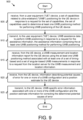
- a location server device apparatus for wireless communication receives, from a user equipment (“UE"), a set of capabilities related to ultra-wideband (“UWB”) positioning for the UE device in response to a request for the set of capabilities, the set of capabilities used to determine at least one UWB positioning method for performing UWB positioning of the UE device.
- the transceiver transmits, to the user equipment (“UE") device, UWB assistance data to perform UWB positioning in response to a request for the assistance information, the assistance information comprising the at least one UWB positioning method for performing UWB positioning.
- the location server device receives, from the UE device, a UWB measurement and location information report for the UE device using the at least one UWB positioning method associated with at least one of a set of timing-based and a set of angular-based UWB measurements in response to a request from the location server for the UWB measurement and location information.
- the location server device receives, from the UE device, information describing potential causes of error for one or more of a UWB configuration and a position estimate for the UE device.
- the location server device transmits, to the UE device, UWB-specific error information associated with one or more of the UWB configuration and the position estimate information for correcting the determined potential causes of error.
- embodiments may be embodied as a system, apparatus, method, or program product. Accordingly, embodiments may take the form of an entirely hardware embodiment, an entirely software embodiment (including firmware, resident software, micro-code, etc.) or an embodiment combining software and hardware aspects.
- the disclosed embodiments may be implemented as a hardware circuit comprising custom very-large-scale integration ("VLSI") circuits or gate arrays, off-the-shelf semiconductors such as logic chips, transistors, or other discrete components.
- VLSI very-large-scale integration
- the disclosed embodiments may also be implemented in programmable hardware devices such as field programmable gate arrays, programmable array logic, programmable logic devices, or the like.
- the disclosed embodiments may include one or more physical or logical blocks of executable code which may, for instance, be organized as an object, procedure, or function.
- embodiments may take the form of a program product embodied in one or more computer readable storage devices storing machine readable code, computer readable code, and/or program code, referred hereafter as code.
- the storage devices may be tangible, non-transitory, and/or non-transmission.
- the storage devices may not embody signals. In a certain embodiment, the storage devices only employ signals for accessing code.
- the computer readable medium may be a computer readable storage medium.
- the computer readable storage medium may be a storage device storing the code.
- the storage device may be, for example, but not limited to, an electronic, magnetic, optical, electromagnetic, infrared, holographic, micromechanical, or semiconductor system, apparatus, or device, or any suitable combination of the foregoing.
- a storage device More specific examples (a non-exhaustive list) of the storage device would include the following: an electrical connection having one or more wires, a portable computer diskette, a hard disk, a random-access memory (“RAM”), a read-only memory (“ROM”), an erasable programmable read-only memory (“EPROM” or Flash memory), a portable compact disc read-only memory (“CD-ROM”), an optical storage device, a magnetic storage device, or any suitable combination of the foregoing.
- a computer readable storage medium may be any tangible medium that can contain or store a program for use by or in connection with an instruction execution system, apparatus, or device.
- Code for carrying out operations for embodiments may be any number of lines and may be written in any combination of one or more programming languages including an object-oriented programming language such as Python, Ruby, Java, Smalltalk, C++, or the like, and conventional procedural programming languages, such as the "C" programming language, or the like, and/or machine languages such as assembly languages.
- the code may execute entirely on the user's computer, partly on the user's computer, as a stand-alone software package, partly on the user's computer and partly on a remote computer or entirely on the remote computer or server.
- the remote computer may be connected to the user's computer through any type of network, including a local area network (“LAN”), wireless LAN (“WLAN”), or a wide area network (“WAN”), or the connection may be made to an external computer (for example, through the Internet using an Internet Service Provider (“ISP”)).
- LAN local area network
- WLAN wireless LAN
- WAN wide area network
- ISP Internet Service Provider
- a list with a conjunction of "and/or” includes any single item in the list or a combination of items in the list.
- a list of A, B and/or C includes only A, only B, only C, a combination of A and B, a combination of B and C, a combination of A and C or a combination of A, B and C.
- a list using the terminology "one or more of” includes any single item in the list or a combination of items in the list.
- one or more of A, B and C includes only A, only B, only C, a combination of A and B, a combination of B and C, a combination of A and C or a combination of A, B and C.
- a list using the terminology “one of” includes one and only one of any single item in the list.
- “one of A, B and C” includes only A, only B or only C and excludes combinations of A, B and C.
- a member selected from the group consisting of A, B, and C includes one and only one of A, B, or C, and excludes combinations of A, B, and C.”
- "a member selected from the group consisting of A, B, and C and combinations thereof” includes only A, only B, only C, a combination of A and B, a combination of B and C, a combination of A and C or a combination of A, B and C.
- the code may also be stored in a storage device that can direct a computer, other programmable data processing apparatus, or other devices to function in a particular manner, such that the instructions stored in the storage device produce an article of manufacture including instructions which implement the function/act specified in the flowchart diagrams and/or block diagrams.
- the code may also be loaded onto a computer, other programmable data processing apparatus, or other devices to cause a series of operational steps to be performed on the computer, other programmable apparatus, or other devices to produce a computer implemented process such that the code which execute on the computer or other programmable apparatus provide processes for implementing the functions/acts specified in the flowchart diagrams and/or block diagrams.
- each block in the flowchart diagrams and/or block diagrams may represent a module, segment, or portion of code, which includes one or more executable instructions of the code for implementing the specified logical function(s).
- the present disclosure describes systems, methods, and apparatuses for ultra-wideband measurements for radio access technology-independent positioning.
- the methods may be performed using computer code embedded on a computer-readable medium.
- an apparatus or system may include a computer-readable medium containing computer-readable code which, when executed by a processor, causes the apparatus or system to perform at least a portion of the below described solutions.
- 5G LCS are inherently part of the 3GPP Architecture and RAN framework to enable the identification and standardized reporting of a UE's or a group of UEs location information based on the supported RAT-dependent and RAT-independent measurements.
- the current issue within the 3GPP framework is the lack of support for enabling high accuracy positioning and/or ranging using UWB signal measurements at the network-side (e.g., UE-assisted) and/or UE-side (e.g., UE-based) positioning.
- UWB has been extensively studied and implemented in commercial products for several years, and it has always been regarded as a well-established wireless technology for high accuracy positioning and tracking for indoor/short range scenarios. UWB has the potential to impact several vertical use cases such as public safety, commercial, automotive, and IIoT scenarios. UWB technology has also been standardized in 802.15.4z (HRP-UWB and LRP-UWB) and IEEE 802.15.6 (wireless body area networks).
- the current 3GPP (new radio (“NR”) and long-term evolution (“LTE”)) design lacks the necessary support for enabling and exploiting RAT-independent UWB-based measurements for enhanced 3GPP UE-assisted, UE-based, or SL-based positioning.
- This provides an additional degree of freedom for hybrid positioning methods involving RAT-independent and RAT-dependent positioning techniques.
- the present disclosure aims to address this key open issue by providing the necessary signaling support for the location management function (“LMF”), gNB, and UE nodes for performing the required UWB positioning procedures and location estimation along the Uu and SL (e.g., PC5) interface.
- LMF location management function
- solutions are presented for supporting UWB measurements to complement the RAT-independent positioning framework.
- the solution proposes the supported UWB positioning methods, UE positioning modes, and types of UWB measurements to be exchanged between the target-UE and the location server, e.g., LMF.
- This use of UWB RAT-independent positioning provides an additional degree of freedom for the use of hybrid positioning technologies within the 3GPP positioning framework.
- UWB RAT-independent positioning can also be flexibly performed along with other SL positioning methods.
- Figure 1 depicts a wireless communication system 100 for ultra-wideband measurements for radio access technology-independent positioning, according to embodiments of the disclosure.
- the wireless communication system 100 includes at least one remote unit 105, a radio access network ("RAN") 120, and a mobile core network 140.
- the RAN 120 and the mobile core network 140 form a mobile communication network.
- the RAN 120 may be composed of a base unit 121 with which the remote unit 105 communicates using wireless communication links 123.
- the RAN 120 is compliant with the 5G system specified in the Third Generation Partnership Project ("3GPP") specifications.
- the RAN 120 may be a Next Generation Radio Access Network ("NG-RAN”), implementing New Radio (“NR”) Radio Access Technology (“RAT”) and/or Long-Term Evolution (“LTE”) RAT.
- the RAN 120 may include non-3GPP RAT (e.g., Wi-Fi ® or Institute of Electrical and Electronics Engineers (“IEEE”) 802.11-family compliant WLAN).
- the RAN 120 is compliant with the LTE system specified in the 3GPP specifications.
- the wireless communication system 100 may implement some other open or proprietary communication network, for example Worldwide Interoperability for Microwave Access (“WiMAX”) or IEEE 802.16-family standards, among other networks.
- WiMAX Worldwide Interoperability for Microwave Access
- IEEE 802.16-family standards among other networks.
- the present disclosure is not intended to be limited to the implementation of any particular wireless communication system architecture or protocol.
- the remote units 105 may include computing devices, such as desktop computers, laptop computers, personal digital assistants ("PDAs"), tablet computers, smart phones, smart televisions (e.g., televisions connected to the Internet), smart appliances (e.g., appliances connected to the Internet), set-top boxes, game consoles, security systems (including security cameras), vehicle on-board computers, network devices (e.g., routers, switches, modems), or the like.
- the remote units 105 include wearable devices, such as smart watches, fitness bands, optical head-mounted displays, or the like.
- the remote units 105 may be referred to as the UEs, subscriber units, mobiles, mobile stations, users, terminals, mobile terminals, fixed terminals, subscriber stations, user terminals, wireless transmit/receive unit (“WTRU”), a device, or by other terminology used in the art.
- the remote unit 105 includes a subscriber identity and/or identification module (“SIM”) and the mobile equipment (“ME”) providing mobile termination functions (e.g., radio transmission, handover, speech encoding and decoding, error detection and correction, signaling and access to the SIM).
- SIM subscriber identity and/or identification module
- ME mobile equipment
- the remote unit 105 may include a terminal equipment ("TE") and/or be embedded in an appliance or device (e.g., a computing device, as described above).
- the remote units 105 may communicate directly with one or more of the base units 121 in the RAN 120 via uplink (“UL") and downlink ("DL”) communication signals. Furthermore, the UL and DL communication signals may be carried over the wireless communication links 123.
- the RAN 120 is an intermediate network that provides the remote units 105 with access to the mobile core network 140.
- the base unit(s) 121 may provide a cell operating using a first frequency range and/or a cell operating using a second frequency range.
- the remote units 105 communicate with an application server 151 via a network connection with the mobile core network 140.
- an application 107 e.g., web browser, media client, telephone and/or Voice-over-Internet-Protocol ("VoIP") application
- VoIP Voice-over-Internet-Protocol
- a remote unit 105 may trigger the remote unit 105 to establish a protocol data unit (“PDU") session (or other data connection) with the mobile core network 140 via the RAN 120.
- the mobile core network 140 then relays traffic between the remote unit 105 and the application server 151 in the packet data network 150 using the PDU session.
- the PDU session represents a logical connection between the remote unit 105 and the User Plane Function ("UPF") 141.
- UPF User Plane Function
- the remote unit 105 In order to establish the PDU session (or PDN connection), the remote unit 105 must be registered with the mobile core network 140 (also referred to as "attached to the mobile core network" in the context of a Fourth Generation ("4G") system). Note that the remote unit 105 may establish one or more PDU sessions (or other data connections) with the mobile core network 140. As such, the remote unit 105 may have at least one PDU session for communicating with the packet data network 150. The remote unit 105 may establish additional PDU sessions for communicating with other data networks and/or other communication peers.
- 4G Fourth Generation
- the base units 121 may be distributed over a geographic region.
- a base unit 121 may also be referred to as an access terminal, an access point, a base, a base station, a Node-B ("NB"), an Evolved Node B (abbreviated as eNodeB or "eNB,” also known as Evolved Universal Terrestrial Radio Access Network (“E-UTRAN”) Node B), a 5G/NR Node B (“gNB”), a Home Node-B, a relay node, a RAN node, or by any other terminology used in the art.
- NB Node-B
- eNB Evolved Node B
- gNB 5G/NR Node B
- the base units 121 are generally part of a RAN, such as the RAN 120, that may include one or more controllers communicably coupled to one or more corresponding base units 121. These and other elements of radio access network are not illustrated but are well known generally by those having ordinary skill in the art.
- the base units 121 connect to the mobile core network 140 via the RAN 120.
- the base units 121 may serve a number of remote units 105 within a serving area, for example, a cell or a cell sector, via a wireless communication link 123.
- the base units 121 may communicate directly with one or more of the remote units 105 via communication signals.
- the base units 121 transmit DL communication signals to serve the remote units 105 in the time, frequency, and/or spatial domain.
- the DL communication signals may be carried over the wireless communication links 123.
- the wireless communication links 123 may be any suitable carrier in licensed or unlicensed radio spectrum.
- the wireless communication links 123 facilitate communication between one or more of the remote units 105 and/or one or more of the base units 121. Note that during NR operation on unlicensed spectrum (referred to as "NR-U”), the base unit 121 and the remote unit 105 communicate over unlicensed (e.g., shared) radio spectrum.
- NR-U unlicensed spectrum
- the mobile core network 140 is a 5GC or an Evolved Packet Core ("EPC"), which may be coupled to a packet data network 150, like the Internet and private data networks, among other data networks.
- a remote unit 105 may have a subscription or other account with the mobile core network 140.
- each mobile core network 140 belongs to a single mobile network operator (“MNO"). The present disclosure is not intended to be limited to the implementation of any particular wireless communication system architecture or protocol.
- the mobile core network 140 includes several network functions (“NFs”). As depicted, the mobile core network 140 includes at least one UPF 141.
- the mobile core network 140 also includes multiple control plane (“CP") functions including, but not limited to, an Access and Mobility Management Function (“AMF”) 143 that serves the RAN 120, a Session Management Function (“SMF”) 145, a Location Management Function (“LMF”) 144, a Unified Data Management function (“UDM””) and a User Data Repository (“UDR”).
- AMF Access and Mobility Management Function
- SMF Session Management Function
- LMF Location Management Function
- UDM Unified Data Management function
- UDR User Data Repository
- the LMF 144 receives positioning measurements or estimates from RAN 120 and the remote unit 105 (e.g., via the AMF 143) and computes the position of the remote unit 105.
- the UDM is responsible for generation of Authentication and Key Agreement ("AKA") credentials, user identification handling, access authorization, subscription management.
- AKA Authentication and Key Agreement
- the UDR is a repository of subscriber information and may be used to service a number of network functions. For example, the UDR may store subscription data, policy-related data, subscriber-related data that is permitted to be exposed to third party applications, and the like.
- the UDM is co-located with the UDR, depicted as combined entity "UDM/UDR" 149.
- the mobile core network 140 may also include a Policy Control Function (“PCF”) (which provides policy rules to CP functions), a Network Repository Function (“NRF”) (which provides Network Function (“NF”) service registration and discovery, enabling NFs to identify appropriate services in one another and communicate with each other over Application Programming Interfaces (“APIs”)), a Network Exposure Function (“NEF”) (which is responsible for making network data and resources easily accessible to customers and network partners), an Authentication Server Function (“AUSF”), or other NFs defined for the 5GC.
- PCF Policy Control Function
- NRF Network Repository Function
- NF Network Function
- AUSF Authentication Server Function
- the AUSF may act as an authentication server and/or authentication proxy, thereby allowing the AMF 143 to authenticate a remote unit 105.
- the mobile core network 140 may include an authentication, authorization, and accounting (“AAA”) server.
- AAA authentication, authorization, and accounting
- a network slice instance may be identified by a single-network slice selection assistance information ("S-NSSAI") while a set of network slices for which the remote unit 105 is authorized to use is identified by network slice selection assistance information (“NSSAI").
- S-NSSAI single-network slice selection assistance information
- NSSAI network slice selection assistance information
- the various network slices may include separate instances of network functions, such as the SMF 145 and UPF 141.
- the different network slices may share some common network functions, such as the AMF 143. The different network slices are not shown in Figure 1 for ease of illustration, but their support is assumed.
- the remote unit 105 receives a positioning measurement configuration 125 from the network (e.g., from the LMF 144 via RAN 120), including a positioning processing timeline for the remote unit 105 based on the remote unit's capabilities.
- the remote unit 105 performs positioning measurements, as described in greater detail below, and sends a positioning report 127 to the LMF 144.
- Figure 1 depicts components of a 5G RAN and a 5G core network
- the described embodiments for ultra-wideband measurements for radio access technology-independent positioning apply to other types of communication networks and RATs, including IEEE 802.11 variants, Global System for Mobile Communications ("GSM", e.g., a 2G digital cellular network), General Packet Radio Service (“GPRS”), Universal Mobile Telecommunications System (“UMTS”), LTE variants, CDMA 2000, Bluetooth, ZigBee, Sigfox, and the like.
- GSM Global System for Mobile Communications
- GPRS General Packet Radio Service
- UMTS Universal Mobile Telecommunications System
- CDMA 2000 Code Division Multiple Access 2000
- Bluetooth ZigBee
- ZigBee ZigBee
- Sigfox and the like.
- the depicted network functions may be replaced with appropriate EPC entities, such as a Mobility Management Entity ("MME"), a Serving Gateway (“SGW”), a PGW, a Home Subscriber Server (“HSS”), and the like.
- MME Mobility Management Entity
- SGW Serving Gateway
- PGW Packet Data Network
- HSS Home Subscriber Server
- the AMF 143 may be mapped to an MME
- the SMF 145 may be mapped to a control plane portion of a PGW and/or to an MME
- the UPF 141 may be mapped to an SGW and a user plane portion of the PGW
- the UDM/UDR 149 may be mapped to an HSS, etc.
- the term "RAN node” is used for the base station but it is replaceable by any other radio access node, e.g., gNB, ng-eNB, eNB, Base Station ("BS”), Access Point ("AP”), etc. Further, the operations are described mainly in the context of 5G NR. However, the proposed solutions/methods are also equally applicable to other mobile communication systems supporting ultra-wideband measurements for radio access technology-independent positioning.
- Figure 2 depicts a NR protocol stack 200, according to embodiments of the disclosure. While Figure 2 shows the UE 205, the RAN node 210 and an AMF 215 in a 5G core network ("5GC"), these are representative of a set of remote units 105 interacting with a base unit 121 and a mobile core network 140. As depicted, the protocol stack 200 comprises a User Plane protocol stack 201 and a Control Plane protocol stack 203.
- 5GC 5G core network
- the User Plane protocol stack 201 includes a physical (“PHY”) layer 220, a Medium Access Control (“MAC”) sublayer 225, the Radio Link Control (“RLC”) sublayer 230, a Packet Data Convergence Protocol (“PDCP”) sublayer 235, and Service Data Adaptation Protocol (“SDAP”) layer 240.
- the Control Plane protocol stack 203 includes a physical layer 220, a MAC sublayer 225, a RLC sublayer 230, and a PDCP sublayer 235.
- the Control Plane protocol stack 203 also includes a Radio Resource Control (“RRC”) layer 245 and a Non-Access Stratum (“NAS”) layer 250.
- RRC Radio Resource Control
- NAS Non-Access Stratum
- the AS layer (also referred to as "AS protocol stack”) for the User Plane protocol stack 201 consists of at least SDAP, PDCP, RLC and MAC sublayers, and the physical layer.
- the AS layer for the Control Plane protocol stack 203 consists of at least RRC, PDCP, RLC and MAC sublayers, and the physical layer.
- the Layer-2 (“L2”) is split into the SDAP, PDCP, RLC and MAC sublayers.
- the Layer-3 (“L3”) includes the RRC sublayer 245 and the NAS layer 250 for the control plane and includes, e.g., an Internet Protocol (“IP”) layer and/or PDU Layer (not depicted) for the user plane.
- IP Internet Protocol
- L1 and L2 are referred to as “lower layers,” while L3 and above (e.g., transport layer, application layer) are referred to as "higher layers” or "upper layers.”
- the physical layer 220 offers transport channels to the MAC sublayer 225.
- the physical layer 220 may perform a Clear Channel Assessment and/or Listen-Before-Talk ("CCA/LBT”) procedure using energy detection thresholds, as described herein.
- the physical layer 220 may send a notification of UL Listen-Before-Talk ("LBT") failure to a MAC entity at the MAC sublayer 225.
- the MAC sublayer 225 offers logical channels to the RLC sublayer 230.
- the RLC sublayer 230 offers RLC channels to the PDCP sublayer 235.
- the PDCP sublayer 235 offers radio bearers to the SDAP sublayer 240 and/or RRC layer 245.
- the SDAP sublayer 240 offers QoS flows to the core network (e.g., 5GC).
- the RRC layer 245 provides for the addition, modification, and release of Carrier Aggregation and/or Dual Connectivity.
- the RRC layer 245 also manages the establishment, configuration, maintenance, and release of Signaling Radio Bearers ("SRBs") and Data Radio Bearers (“DRBs").
- SRBs Signaling Radio Bearers
- DRBs Data Radio Bearers
- the NAS layer 250 is between the UE 205 and the 5GC 215. NAS messages are passed transparently through the RAN.
- the NAS layer 250 is used to manage the establishment of communication sessions and for maintaining continuous communications with the UE 205 as it moves between different cells of the RAN.
- the AS layer is between the UE 205 and the RAN (e.g., RAN node 210) and carries information over the wireless portion of the network.
- Table 1 shows positioning performance requirements for different scenarios in an Industrial IoT ("IIoT”) or indoor factory setting.
- IIoT Positioning Performance Requirements Scenario Horizontal accuracy Vertical accuracy Availability Latency for position estimation of UE UE Speed Corresponding Positioning Service Level Mobile control panels with safety functions (non-danger zones) ⁇ 5 m ⁇ 3 m 90 % ⁇ 5 s N/A Service Level 2 Process automation - plant asset management ⁇ 1 m ⁇ 3 m 90 % ⁇ 2 s ⁇ 30 km/h Service Level 3
- Flexible, modular assembly area in smart factories (for tracking of tools at the work-place location) ⁇ 1 m (relative positioning ) N/A 99 % 1 s ⁇ 30 km/h Service Level 3 Augmented reality in smart factories ⁇ 1 m ⁇ 3 m 99 % ⁇ 15 ms ⁇ 10 km
- Some UE positioning method supported in Rel-16 are listed in Table 2.
- the separate positioning techniques as indicated in Table 2 may be currently configured and performed based on the requirements of the LMF and/or UE capabilities.
- Table 2 includes TBS positioning based on PRS signals, but only OTDOA based on LTE signals is supported.
- the E-CID includes Cell-ID for NR method.
- the Terrestrial Beacon System (“TBS”) method refers to TBS positioning based on Metropolitan Beacon System (“MBS”) signals.
- Table 2 Supported Rel-16 UE positioning methods
- Method UE-based UE-assisted, LMF-based NG-RAN node assisted Secure User Plane Location (“SUPL") A-GNSS Yes Yes No Yes (UE-based and UE-assisted)
- E-CID No Yes Yes Yes for E-UTRA UE-assisted
- E-CID No Yes FFS No UL-TDOA No No Yes No UL-AoA No No Yes No Yes No Yes No
- LCS Lcoma Network Service Set
- TS 23.271 TS 23.271
- TS 23.501 and TS 23.273 The overall sequence of events applicable to the UE, NG-RAN and LMF for any location service is shown in Figure 3 .
- the AMF 305 when the AMF 305 receives a Location Service Request in case of the UE 301 is in CM-IDLE state, the AMF 305 performs a network triggered service request as defined in TS 23.502 and TS 23.273 in order to establish a signaling connection with the UE 301 and assign a specific serving gNB or ng-eNB.
- the UE 301 is assumed to be in connected mode before the beginning of the flow shown in the Figure 3 ; that is, any signaling that might be required to bring the UE 301 to connected mode prior to step 1a is not shown.
- the signaling connection may, however, be later released (e.g., by the NG-RAN 303 node as a result of signaling and data inactivity) while positioning is still ongoing.
- step 1a in one embodiment, some entity in the 5GC 309 (e.g., GMLC) requests (see messaging 302) some location service (e.g., positioning) for a target UE 301 to the serving AMF 305.
- some location service e.g., positioning
- the serving AMF 305 for a target UE 301 determines (see block 304) the need for some location service (e.g., to locate the UE 301 for an emergency call).
- step 1c in one embodiment, the UE 301 requests (see messaging 306) some location service (e.g., positioning or delivery of assistance data) to the serving AMF 305 at the NAS level.
- the AMF 305 transfers (see messaging 308) the location service request to an LMF 307.
- the LMF 307 instigates location procedures (see block 310) with the serving and possibly neighboring ng-eNB or gNB in the NG-RAN 303, e.g., to obtain positioning measurements or assistance data.
- the LMF 307 instigates location procedures (see block 312) with the UE 301, e.g., to obtain a location estimate or positioning measurements or to transfer location assistance data to the UE 301.
- the LMF 307 provides (see messaging 314) a location service response to the AMF 305 and includes any needed results, e.g., success or failure indication and, if requested and obtained, a location estimate for the UE.
- step 5a in one embodiment, if step 1a was performed, the AMF 305 returns a location service response (see messaging 316) to the 5GC entity 309 in step 1a and includes any needed results, e.g., a location estimate for the UE 301.
- step 5b in one embodiment, if step 1b occurred, the AMF 305 uses the location service response (see block 318) received in step 4 to assist the service that triggered this in step 1b (e.g., may provide a location estimate associated with an emergency call to a GMLC).
- step 5c in one embodiment, if step 1c was performed, the AMF 305 returns (see messaging 320) a location service response to the UE 301 and includes any needed results, e.g., a location estimate for the UE 301.
- Steps 3a and 3b can involve the use of different position methods to obtain location related measurements for a target UE and from these compute a location estimate and possibly additional information like velocity.
- the case that the NG-RAN node functions as an LCS client is not supported in this version of the specification.
- the following RAT-dependent positioning techniques may be supported by the system 100:
- the DL TDOA positioning method makes use of the DL RS Time Difference ("RSTD") (and optionally DL PRS RS Received Power ("RSRP") of DL PRS RS Received Quality (“RSRQ”)) of downlink signals received from multiple TPs, at the UE (e.g., remote unit 105).
- the UE measures the DL RSTD (and optionally DL PRS RSRP) of the received signals using assistance data received from the positioning server, and the resulting measurements are used along with other configuration information to locate the UE in relation to the neighboring Transmission Points ("TPs").
- TPs Transmission Points
- the DL-AoD The DL Angle of Departure ("AoD") positioning method makes use of the measured DL PRS RSRP of downlink signals received from multiple TPs, at the UE.
- the UE measures the DL PRS RSRP of the received signals using assistance data received from the positioning server, and the resulting measurements are used along with other configuration information to locate the UE in relation to the neighboring TPs.
- Multi-RTT The Multiple-Round Trip Time (“Multi-RTT”) positioning method makes use of the UE Receive-Transmit (“Rx-Tx”) measurements and DL PRS RSRP of downlink signals received from multiple TRPs, measured by the UE and the gNB Rx-Tx measurements (e.g., measured by RAN node) and UL SRS-RSRP at multiple TRPs of uplink signals transmitted from UE.
- Rx-Tx Receive-Transmit
- the UE measures the UE Rx-Tx measurements (and optionally DL PRS RSRP of the received signals) using assistance data received from the positioning server, and the TRPs measure the gNB Rx-Tx measurements (and optionally UL SRS-RSRP of the received signals) using assistance data received from the positioning server.
- the measurements are used to determine the Round Trip Time ("RTT") at the positioning server which are used to estimate the location of the UE.
- RTT Round Trip Time
- E-CID/ NR E-CID Enhanced Cell ID (CID) positioning method, the position of a UE is estimated with the knowledge of its serving ng-eNB, gNB and cell and is based on LTE signals. The information about the serving ng-eNB, gNB and cell may be obtained by paging, registration, or other methods.
- NR Enhanced Cell ID (NR E CID) positioning refers to techniques which use additional UE measurements and/or NR radio resource and other measurements to improve the UE location estimate using NR signals.
- NR E-CID positioning may utilize some of the same measurements as the measurement control system in the RRC protocol, the UE generally is not expected to make additional measurements for the sole purpose of positioning; e.g., the positioning procedures do not supply a measurement configuration or measurement control message, and the UE reports the measurements that it has available rather than being required to take additional measurement actions.
- the UL TDOA positioning method makes use of the UL TDOA (and optionally UL SRS-RSRP) at multiple RPs of uplink signals transmitted from the UE.
- the RPs measure the UL TDOA (and optionally UL SRS-RSRP) of the received signals using assistance data received from the positioning server, and the resulting measurements are used along with other configuration information to estimate the location of the UE.
- the UL-AoA The UL Angle of Arrival (“AoA") positioning method makes use of the measured azimuth and the zenith angles of arrival at multiple RPs of uplink signals transmitted from the UE.
- the RPs measure A-AoA and Z-AoA of the received signals using assistance data received from the positioning server, and the resulting measurements are used along with other configuration information to estimate the location of the UE.
- Figure 4 depicts a system 400 for NR beam-based positioning.
- the PRS can be transmitted by different base stations (serving and neighboring) using narrow beams over Frequency Range #1 Between (“FR1”, e.g., frequencies from 410 MHz to 7125 MHz) and Frequency Range #2 (“FR2”, e.g., frequencies from 24.25 GHz to 52.6 GHz), which is relatively different when compared to LTE where the PRS was transmitted across the whole cell.
- FR1 Frequency Range #1 Between
- FR2 Frequency Range #2
- a UE 405 may receive PRS from a first gNB ("gNB 3") 410, which is a serving gNB, and also from a neighboring second gNB ("gNB 1") 415, and a neighboring third gNB (“gNB 2") 420.
- the PRS can be locally associated with a set of PRS Resources grouped under a Resource Set ID for a base station (e.g., TRP).
- each gNB 410, 415, 420 is configured with a first Resource Set ID 425 and a second Resource Set ID 430.
- the UE 405 receives PRS on transmission beams; here, receiving PRS from the gNB 3 410 on a set of PRS Resources 435 from the second Resource Set ID 430, receiving PRS from the gNB 1 415 on a set of PRS Resources 435 from the second Resource Set ID 430, and receiving PRS from the gNB 2 420 on a set of PRS Resources 435 from the first Resource Set ID 425.
- UE positioning measurements such as Reference Signal Time Difference ("RSTD") and PRS RSRP measurements are made between beams as opposed to different cells as was the case in LTE.
- RSTD Reference Signal Time Difference
- PRS RSRP PRS RSRP measurements
- Table 3 lists the RS-to-measurements mapping required for each of the supported RAT-dependent positioning techniques at the UE
- Table 4 lists the RS-to-measurements mapping required for each of the supported RAT-dependent positioning techniques at the gNB.
- Table 3 UE Measurements to enable RAT-dependent positioning techniques DL/UL Reference Signals UE Measurements To facilitate support of the following positioning techniques Rel-16 DL PRS DL RSTD DL-TDOA Rel-16 DL PRS DL PRS RSRP DL-TDOA, DL-AoD, Multi-RTT Rel-16 DL PRS / Rel-16 SRS for positioning UE Rx-Tx time difference Multi-RTT Rel.
- RAT-dependent positioning techniques involve the 3GPP RAT and core network entities to perform the position estimation of the UE, which are differentiated from RAT-independent positioning techniques which rely on Global Navigation Satellite System (“GNSS”), Inertial Measurement Unit (“IMU”) sensor, WLAN and Bluetooth technologies for performing target device (e.g., UE) positioning.
- GNSS Global Navigation Satellite System
- IMU Inertial Measurement Unit
- WLAN Wireless Local Area Network
- GNSS Various RAT-Independent positioning techniques may be used. For instance, in network-assisted GNSS methods, these methods make use of UEs that are equipped with radio receivers capable of receiving GNSS signals. In 3GPP specifications the term GNSS encompasses both global and regional/augmentation navigation satellite systems.
- GNSS Quasi Zenith Satellite System
- SBAS Space Based Augmentation Systems
- different GNSSs can be used separately or in combination to determine the location of a UE.
- the barometric pressure sensor method makes use of barometric sensors to determine the vertical component of the position of the UE.
- the UE measures barometric pressure, optionally aided by assistance data, to calculate the vertical component of its location or to send measurements to the positioning server for position calculation. This method should be combined with other positioning methods to determine the 3D position of the UE.
- the WLAN positioning method makes use of the WLAN measurements (AP identifiers and optionally other measurements) and databases to determine the location of the UE.
- the UE measures received signals from WLAN access points, optionally aided by assistance data, to send measurements to the positioning server for position calculation. Using the measurement results and a references database, the location of the UE is calculated.
- the UE makes use of WLAN measurements and optionally WLAN AP assistance data provided by the positioning server, to determine its location.
- the Bluetooth positioning method makes use of Bluetooth measurements (beacon identifiers and optionally other measurements) to determine the location of the UE.
- the UE measures received signals from Bluetooth beacons. Using the measurement results and a references database, the location of the UE is calculated.
- the Bluetooth methods may be combined with other positioning methods (e.g., WLAN) to improve positioning accuracy of the UE.
- a Terrestrial Beacon System used for positioning, consists of a network of ground-based transmitters, broadcasting signals only for positioning purposes.
- the current type of TBS positioning signals are the Metropolitan Beacon System (“MBS”) signals and Positioning Reference Signals (“PRS”) ( see TS 36.211).
- MBS Metropolitan Beacon System
- PRS Positioning Reference Signals
- the UE measures received TBS signals, optionally aided by assistance data, to calculate its location or to send measurements to the positioning server for position calculation.
- the motion sensor method makes use of different sensors such as accelerometers, gyros, magnetometers, to calculate the displacement of UE.
- the UE estimates a relative displacement based upon a reference position and/or reference time.
- UE sends a report comprising the determined relative displacement which can be used to determine the absolute position. This method should be used with other positioning methods for hybrid positioning.
- Embodiment 1 Details the supported positioning modes and measurements required to be reported for performing UWB ranging/positioning including timing-based and angular-based positioning methods.
- Embodiment 2 Defines the information that may need to be transferred between various network entities including UE, NG-RAN and gNB to enable UWB positioning as part of the 3GPP framework. These may include the type of ranging measurements required for relative position estimation.
- Embodiment 3 Describes the NR positioning procedures required for enabling UWB positioning including the necessary triggers, configuration and report signalling between UE and LMF.
- the benefits of the solutions herein include the addition of a high-accuracy RAT-independent positioning technology such as UWB within the 3GPP framework.
- a high-accuracy RAT-independent positioning technology such as UWB within the 3GPP framework.
- UWB a high-accuracy RAT-independent positioning technology
- This enables a further degree of freedom with respect to the available positioning technology choices for a UE of perform Hybrid positioning, e.g., using a combination of RAT-dependent and RAT-independent positioning techniques.
- the specification of exploiting UWB measurements for high-accuracy positioning can increase the existing accuracy for computing the location estimate using 3GPP entities (e.g., UE or LMF), especially in short range indoor environments.
- 3GPP entities e.g., UE or LMF
- Embodiments 1-3 describe the details to include UWB-based positioning in the current 3GPP positioning framework as well as corresponding enhancements.
- Embodiments 1-3 can be implemented in combination with each other to achieve an improved location accuracy estimate using UWB positioning techniques using the Uu and PC5 interface.
- the target-UE may also be supported and signaled with the following positioning modes in relation to UWB RAT-independent positioning/ranging using network assistance (Uu interface) and/or sidelink assistance (PC5 interface):
- Uu interface network assistance
- PC5 interface sidelink assistance
- the location server or base station equipped with a Location Measurement Unit may signal the positioning modes using LPP/RRC/MAC CE signaling.
- the UE may indicate the employed or desired positioning mode via LPP/RRC to the location server or base station equipped with an LMU.
- the proposed UWB RAT-independent positioning method may be used in at least one or more combinations of either, RAT-dependent positioning methods as listed in Table 3 and Table 4, or other RAT-independent positioning methods listed above, to improve the overall location and tracking accuracy of the target-UE as part of a hybrid positioning method.
- This hybrid positioning method may be triggered at the target-UE or location server and corresponding information regarding the employed positioning methods may be signaled to the corresponding node, e.g., location server, base station, or target-UE. This can be applicable to positioning methods along the Uu and SL interface.
- the UWB ranging and localization components normally comprises of an anchor (fixed unit with a known location), tags (devices to be localized, may be stationary or mobile) and a location engine and/or server, which may be co-located or be based in the cloud.
- positioning may occur between two entities (tags or UEs) in a peer-to-peer fashion, without assistance from an anchor/access point/gNB.
- Table 5 indicates the exemplary supported positioning methods that enable ranging between a UWB transmitter ("TX") and receiver ("RX"). These type of positioning techniques can be signaled to the location server, e.g., LMF in addition to the computed UE's location using UWB or a hybrid positioning technique involving UWB localization.
- the positioning capabilities include support for absolute and relative positioning.
- the UE UWB measurements that may be exchanged with the network may broadly relate to supporting the following positioning techniques:
- An anchor node may also refer to either a UWB access point, distributed gNB with UWB functionality or a UE.
- the above positioning methods may be applicable to the previously listed positioning modes.
- a combination of two or positioning techniques may also be applicable, e.g., TWR together with Phase difference of Arrival may be used to obtain a location estimate in 3D space.
- the key measurements for UWB ranging are performed with respect to the transmitted and response frame.
- the transmitted may include control message frame or data frame while the response frame may include an ACK/NACK frame or a measurement report frame.
- the aforementioned mentioned measurement report frame is referred to as the RFRAME.
- the TX and RX each capture timestamp report which can be shared within the NR positioning framework to entities such as the LMF or UE.
- the UE and LMF may exchange assistance data information related to UWB positioning depending on the capabilities at each of these entities. This is applicable for both UE-based and UE-assisted positioning.
- Exemplary assistance data that may be transferred from LMF to UE may include information related to the anchor nodes/beacons as seen in Table 6.
- Table 2 Assistance Data from LMF to target-UE Assistance Data UWB Anchor Node/Beacon List including channel assignments Anchor Node IDs Anchor Node USS ID Anchor Node/Beacon Location Information
- the location server e.g., LMF can provide a UWB Anchor/Beacon list, which consists of all available anchor nodes in the vicinity of the target-UE to be localized including any associated identifiers differentiating the anchor nodes and corresponding channel frequency assignments.
- the UWB Secure Service (“USS”) ID can also be shared (if available) with the target-UE since it provides secure routing feature for higher layers.
- the location information of anchor nodes/beacons can also be provided to the target-UE.
- the information provided to the LMF for UWB RAT-independent target-UE positioning can be further divided into three cases based on the operating positioning mode employed by the target-UE with UWB capabilities: 1) UE-assisted, 2) UE-Based, and 3) Standalone positioning.
- Table 7 is a breakdown of the information that may be signaled to the LMF from the target-UE via LPP/positioning-based protocol based on the supported aforementioned positioning modes and a required to UWB positioning as per the secure ranging standard.
- An alternate implementation may include support for SL-based positioning modes for UWB RAT-independent positioning, which can be further divided into SL UE-assisted and SL UE-based positioning modes as noted in Table 7.
- Table 7 UWB measurement/location information signaled from target-UE to LMF Information UE-Assisted UE-Based Standalone SL UE-Assisted SL UE-Based UWB Location Information/Measurements Timestamp Yes No No Yes No Security Level Yes No Yes No Key Source Yes No No Yes No Key ID Mode Yes No Yes No Key Index Yes No No Yes No Ranging CounterStart Yes No No Yes No Ranging CounterStop Yes No No Yes No Ranging Tracking Interval Yes No No Yes No Yes No Ranging Offset Yes No No Yes No Yes No Ranging From Yes No No Yes No Angle-of-Arrival Azimuth Yes No Yes No Angle-of-Arrival Elevation Yes No No Yes No Angle-of- Arrival Supported Yes No No Yes No Yes No RSSI (Received Signal Strength Indicator) Yes No No Yes No Yes No Target-UE Location Information Absolute target-UE position estimate with uncertainty shape using UWB positioning No Yes Yes Yes No Yes Relative target-UE position estimate with uncertainty shape using UWB positioning No Yes Yes Yes Position
- the above parameters can be measured with respect to STS-ranging (scrambled time sequence) ranging and can be also signaled to the location server, if supported (enhanced ranging device ("ERDEV”) or simply ranging device (“RDEV”).
- the parameters in Table 7 may be signaled to a serving base station equipped with an LMU (location management functionality) using RRC/MAC CE signaling.
- the location information comprising of the position estimate/velocity estimates may also be transmitted to the location server.
- the signaling message UWB-RequestAssistanceData is used by the target device (e.g., UE 501) to request (see messaging 502) UWB assistance data from a location server such as the LMF 503, while the exemplary message, UWB-ProvideAssistanceData, may be used by the location server 503 to provide (see messaging 504) UWB assistance data to enable UE-based or UE-assisted UWB positioning.
- the target device e.g., UE 501
- UWB assistance data from a location server such as the LMF 503
- UWB-ProvideAssistanceData may be used by the location server 503 to provide (see messaging 504) UWB assistance data to enable UE-based or UE-assisted UWB positioning.
- the UE 501 may determine the type of UWB assistance data it may require and indicate this via the exemplary UWB-RequestAssistanceData message. It may also be used to provide specific error messages in the case of any misconfiguration related to the UWB positioning system.
- the assistance data may be transferred to the UE 501 in a single message, while alternate implementations may allow the assistance data message to be segmented into several messages. This may occur if the message size exceeds the allowable limit for transfer in a single message.
- the UWB assistance data may be further broadcasted to target-UEs as part of positioning system information blocks (posSIBs) upon request (on-demand posSIB request) or triggered by the LMF 503 and gNB.
- posSIBs positioning system information blocks
- Step 2 of Figure 5A can also contain the supported channel frequency assignments where a particular UWB positioning method is supported depending on if HRP-UWB or LRP-UWB is configured.
- Table 8 shows an exemplary list of the different UWB channel assignments, which can be signaled to the UE: Table 3: UWB Channel Assignments Band Group Channel Number Centre Frequency (MHz) Bandwidth (MHz) (-3dB) Mandatory/Optional 0 0 499.2 499.2 Mandatory (below 1GHz) 1 1 3494.4 499.2 Optional 2 3993.6 499.2 Optional 3 4492.8 499.2 Mandatory 4 3993.6 1331.2 Optional 2 5 6489.6 499.2 Optional 6 6988.8 499.2 Optional 7 6489.6 1081.6 Optional 8 7488.0 499.2 Optional 9 7987.2 499.2 Mandatory 10 8486.4 499.2 Optional 11 7987.2 1331.2 Optional 12 8985.6 499.2 Option
- the UWB assistance data may include location information of the various anchor nodes/beacons in a given geographic area in which the target-UE is to be absolutely or relatively localized.
- the location information may include latitude and longitude points and corresponding uncertainty points, e.g., as defined in TS 23.032.
- a message e.g. UWB-RequestLocationlnformation is used by the location server 503 to request (see messaging 506) UWB measurements/location estimate from a target-UE 501 or a set of target-UEs, while an exemplary signaling message such as UWB-ProvideLocationlnformation is used by the target device 501 to provide (see messaging 508) measurements or location information for one or more UWB anchor nodes with the associated UWB channels to the location server.
- UWB-RequestLocationlnformation is used by the location server 503 to request (see messaging 506) UWB measurements/location estimate from a target-UE 501 or a set of target-UEs
- an exemplary signaling message such as UWB-ProvideLocationlnformation is used by the target device 501 to provide (see messaging 508) measurements or location information for one or more UWB anchor nodes with the associated UWB channels to the location server.
- Such location information may comprise absolute and relative location data, latitude points, longitude points, horizontal and vertical velocity estimates, positioning and velocity uncertainty values, positioning error, heading information, 3D location estimates including elevation information, integrity of positioning estimates and quality of positioning estimate metrics. It may also provide some relative location measurements with respect to other target-UEs 501. Additionally, the utilized positioning methods may also be signaled to the LMF 503 together with the UWB measurements as indicated in Table 5. The target-UE 501 may also provide the necessary accuracy and integrity information to the LMF 503. It may also be used to provide error-specific messages in the case of any misconfiguration related to the UWB positioning system. The location server 503 may request the UWB-related measurements from the target-UE 501 as denoted in Table 7.
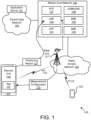
- UWB Request and Provide Capability Information shown in Figure 5C , a message, such as UWB-RequestCapabilities is used by the location server 503 to request (see messaging 510) UWB positioning capabilities information from a target-UE 501, while an exemplary message such as UWB-ProvideCapabilites is used by the target-UE 501 to provide (see messaging 512) its UWB positioning capabilities to the location server 503.
- UWB-RequestCapabilities is used by the location server 503 to request (see messaging 510) UWB positioning capabilities information from a target-UE 501
- UWB-ProvideCapabilites is used by the target-UE 501 to provide (see messaging 512) its UWB positioning capabilities to the location server 503.
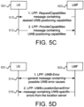
- an exemplary message such as a general UWB-Error message is used by the location server 503 or target device 501 to provide (see messaging 514) an indication of such error causes to the corresponding node.
- the type of error in addition to the originating node (target-UE 501 or location server 503) causing the error may also be indicated the via this message.
- the integrity of the UWB positioning estimate may also be signaled via a separate message (see messaging 516) in alternate implementations.
- the potential error causes are from the location server side 503 (UWB configuration) or from the UE-side 501 (internal error related to any UWB measurement processing or the positioning estimate provided from the UE).
- examples could be the unavailability of a UWB configuration, availability of a partial configuration, or an expired configuration that could result in an UWB configuration error cause.
- Uncertainty information can be determined by comparing the desired location uncertainty e.g., 5%, 2%, 1% location certainty with the current calculated location estimate and see if it meets the provided uncertainty requirements. Uncertainty described herein may be different from the positioning estimate error in the sense that the positioning estimate error is determined when there is an issue with the positioning algorithm internal to the UE 501, while uncertainty assumes that the position estimate has already been calculated within some confidence intervals.
- Figure 6 depicts a user equipment apparatus 600 that may be used for ultra-wideband measurements for radio access technology-independent positioning, according to embodiments of the disclosure.
- the user equipment apparatus 600 is used to implement one or more of the solutions described above.
- the user equipment apparatus 600 may be one embodiment of the remote unit 105 and/or the UE 205, described above.
- the user equipment apparatus 600 may include a processor 605, a memory 610, an input device 615, an output device 620, and a transceiver 625.
- the input device 615 and the output device 620 are combined into a single device, such as a touchscreen.
- the user equipment apparatus 600 may not include any input device 615 and/or output device 620.
- the user equipment apparatus 600 may include one or more of: the processor 605, the memory 610, and the transceiver 625, and may not include the input device 615 and/or the output device 620.
- the transceiver 625 includes at least one transmitter 630 and at least one receiver 635.
- the transceiver 625 communicates with one or more cells (or wireless coverage areas) supported by one or more base units 121.
- the transceiver 625 is operable on unlicensed spectrum.
- the transceiver 625 may include multiple UE panels supporting one or more beams.
- the transceiver 625 may support at least one network interface 640 and/or application interface 645.
- the application interface(s) 645 may support one or more APIs.
- the network interface(s) 640 may support 3GPP reference points, such as Uu, N1, PC5, etc. Other network interfaces 640 may be supported, as understood by one of ordinary skill in the art.
- the processor 605 may include any known controller capable of executing computer-readable instructions and/or capable of performing logical operations.
- the processor 605 may be a microcontroller, a microprocessor, a central processing unit ("CPU"), a graphics processing unit (“GPU”), an auxiliary processing unit, a field programmable gate array (“FPGA”), or similar programmable controller.
- the processor 605 executes instructions stored in the memory 610 to perform the methods and routines described herein.
- the processor 605 is communicatively coupled to the memory 610, the input device 615, the output device 620, and the transceiver 625.
- the processor 605 controls the user equipment apparatus 600 to implement the above described UE behaviors.
- the processor 605 may include an application processor (also known as “main processor”) which manages application-domain and operating system (“OS”) functions and a baseband processor (also known as “baseband radio processor”) which manages radio functions.
- an application processor also known as “main processor” which manages application-domain and operating system (“OS) functions
- a baseband processor also known as “baseband radio processor” which manages radio functions.
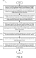
- the transceiver 625 transmits, to a location server of a mobile wireless communication network, a set of capabilities related to ultra-wideband ("UWB") positioning for the UE device in response to a request from the location server for the set of capabilities, the set of capabilities used to determine at least one UWB positioning method for performing UWB positioning of the UE device.
- UWB ultra-wideband
- the transceiver 625 receives, from the location server, UWB assistance data to perform UWB positioning in response to a request for the assistance information, the assistance information comprising the at least one UWB positioning method for performing UWB positioning. In one embodiment, the transceiver 625 transmits, to the location server, a UWB measurement and location information report for the UE device using the at least one UWB positioning method associated with at least one of a set of timing-based and a set of angular-based UWB measurements in response to a request from the location server for the UWB measurement and location information.
- the processor 605 determines information for potential causes of error for one or more of a UWB configuration and a position estimate for the UE device.
- the transceiver transmits, to the location server, the determined information for the potential causes of error.
- the transceiver 625 receives, from the location server, UWB-specific error information associated with one or more of the UWB configuration and the position estimate information for correcting the determined potential causes of error.
- the location server is one or more of part of a core network and co-located with a base station of the mobile wireless communication network.
- the transceiver 625 transmits the location information to the base station equipped with a location measurement unit ("LMU") using the at least one UWB positioning method in response to a request from the base station for the location information.
- LMU location measurement unit
- the UWB assistance data is received at the UE device in a dedicated manner using long-term evolution positioning protocol ("LPP") signaling in response to a request from the UE device.
- LPP long-term evolution positioning protocol
- the UWB assistance data is received at the UE device in a broadcast signal as part of positioning system information blocks (“posSIBs") triggered by one or more of the location server and a base station.
- posSIBs positioning system information blocks
- the UWB assistance data is received at the UE device in a broadcast signal as part of positioning system information blocks ("posSIBs") in response to an on-demand posSIB request by the UE device.
- the UWB assistance information comprises UWB channel assignment information, anchor node identifiers, and anchor node location information.
- the transceiver 625 indicates a type of UWB positioning method utilized to compute the location information along with the transmission of the location information comprising at least one selected from the group of two-way ranging, phase difference of arrival, and time difference of arrival.
- the location information comprises at least one selected from the group of: absolute and relative location data, latitude points, longitude points, horizontal and vertical velocity estimates, positioning and velocity uncertainty values, positioning error, heading information, 3D location estimates, elevation information, integrity of positioning estimates, and quality of positioning estimate metrics.
- the transceiver 625 receives a positioning mode from the location service for UWB RAT-independent positioning, the positioning mode comprising at least one selected from the group of: standalone mode, UE-assisted mode, UE-based mode, and sidelink-based positioning mode.
- the transceiver 625 transmits ranging measurements according to the received positioning mode to the location server, the supported ranging measurements comprising at least one selected from the group of timestamp, ranging counter, ranging offset, angle-of-arrival support indication, angle-of-arrival azimuth, angle-of-arrival elevation, received signal strength indicator.
- the processor 605 determines one or more of absolute and relative positioning and velocity estimates for the UE device based on the UWB positioning method. In one embodiment, the processor 605 enhances location and tracking accuracy of the UE device by combining the UWB positioning method at least one or more combinations of RAT-dependent positioning methods and other RAT-independent positioning methods.
- the transceiver 625 transmits an error type indication depending on if the error cause originates at the UE or location server.
- the processor 605 utilizes a Uu interface between the UE device and a base station and a sidelink interface between the UE device and a peer UE device for transmitting and receiving information related to the UWB positioning method.
- the memory 610 in one embodiment, is a computer readable storage medium.
- the memory 610 includes volatile computer storage media.
- the memory 610 may include a RAM, including dynamic RAM (“DRAM”), synchronous dynamic RAM (“SDRAM”), and/or static RAM (“SRAM”).
- the memory 610 includes non-volatile computer storage media.
- the memory 610 may include a hard disk drive, a flash memory, or any other suitable non-volatile computer storage device.
- the memory 610 includes both volatile and non-volatile computer storage media.
- the memory 610 stores data related to ultra-wideband measurements for radio access technology-independent positioning.
- the memory 610 may store various parameters, panel/beam configurations, resource assignments, policies, and the like as described above.
- the memory 610 also stores program code and related data, such as an operating system or other controller algorithms operating on the apparatus 600.
- the input device 615 may include any known computer input device including a touch panel, a button, a keyboard, a stylus, a microphone, or the like.
- the input device 615 may be integrated with the output device 620, for example, as a touchscreen or similar touch-sensitive display.
- the input device 615 includes a touchscreen such that text may be input using a virtual keyboard displayed on the touchscreen and/or by handwriting on the touchscreen.
- the input device 615 includes two or more different devices, such as a keyboard and a touch panel.
- the output device 620 in one embodiment, is designed to output visual, audible, and/or haptic signals.
- the output device 620 includes an electronically controllable display or display device capable of outputting visual data to a user.
- the output device 620 may include, but is not limited to, a Liquid Crystal Display (“LCD”), a Light-Emitting Diode (“LED”) display, an Organic LED (“OLED”) display, a projector, or similar display device capable of outputting images, text, or the like to a user.
- LCD Liquid Crystal Display
- LED Light-Emitting Diode
- OLED Organic LED
- the output device 620 may include a wearable display separate from, but communicatively coupled to, the rest of the user equipment apparatus 600, such as a smart watch, smart glasses, a heads-up display, or the like. Further, the output device 620 may be a component of a smart phone, a personal digital assistant, a television, a table computer, a notebook (laptop) computer, a personal computer, a vehicle dashboard, or the like.
- the output device 620 includes one or more speakers for producing sound.
- the output device 620 may produce an audible alert or notification (e.g., a beep or chime).
- the output device 620 includes one or more haptic devices for producing vibrations, motion, or other haptic feedback.
- all, or portions of the output device 620 may be integrated with the input device 615.
- the input device 615 and output device 620 may form a touchscreen or similar touch-sensitive display. In other embodiments, the output device 620 may be located near the input device 615.
- the transceiver 625 communicates with one or more network functions of a mobile communication network via one or more access networks.
- the transceiver 625 operates under the control of the processor 605 to transmit messages, data, and other signals and also to receive messages, data, and other signals.
- the processor 605 may selectively activate the transceiver 625 (or portions thereof) at particular times in order to send and receive messages.
- the transceiver 625 includes at least transmitter 630 and at least one receiver 635.
- One or more transmitters 630 may be used to provide UL communication signals to a base unit 121, such as the UL transmissions described herein.
- one or more receivers 635 may be used to receive DL communication signals from the base unit 121, as described herein.
- the user equipment apparatus 600 may have any suitable number of transmitters 630 and receivers 635.
- the transmitter(s) 630 and the receiver(s) 635 may be any suitable type of transmitters and receivers.
- the transceiver 625 includes a first transmitter/receiver pair used to communicate with a mobile communication network over licensed radio spectrum and a second transmitter/receiver pair used to communicate with a mobile communication network over unlicensed radio spectrum.
- the first transmitter/receiver pair used to communicate with a mobile communication network over licensed radio spectrum and the second transmitter/receiver pair used to communicate with a mobile communication network over unlicensed radio spectrum may be combined into a single transceiver unit, for example a single chip performing functions for use with both licensed and unlicensed radio spectrum.
- the first transmitter/receiver pair and the second transmitter/receiver pair may share one or more hardware components.
- certain transceivers 625, transmitters 630, and receivers 635 may be implemented as physically separate components that access a shared hardware resource and/or software resource, such as for example, the network interface 640.
- one or more transmitters 630 and/or one or more receivers 635 may be implemented and/or integrated into a single hardware component, such as a multi-transceiver chip, a system-on-a-chip, an Application-Specific Integrated Circuit ("ASIC"), or other type of hardware component.
- one or more transmitters 630 and/or one or more receivers 635 may be implemented and/or integrated into a multi-chip module.
- other components such as the network interface 640 or other hardware components/circuits may be integrated with any number of transmitters 630 and/or receivers 635 into a single chip.
- the transmitters 630 and receivers 635 may be logically configured as a transceiver 625 that uses one more common control signals or as modular transmitters 630 and receivers 635 implemented in the same hardware chip or in a multi-chip module.
- Figure 7 depicts a network apparatus 700 that may be used for ultra-wideband measurements for radio access technology-independent positioning, according to embodiments of the disclosure.
- network apparatus 700 may be one implementation of a RAN node, such as the base unit 121 and/or the RAN node 210, as described above.
- the base network apparatus 700 may include a processor 705, a memory 710, an input device 715, an output device 720, and a transceiver 725.
- the input device 715 and the output device 720 are combined into a single device, such as a touchscreen.
- the network apparatus 700 may not include any input device 715 and/or output device 720.
- the network apparatus 700 may include one or more of: the processor 705, the memory 710, and the transceiver 725, and may not include the input device 715 and/or the output device 720.
- the transceiver 725 includes at least one transmitter 730 and at least one receiver 735.
- the transceiver 725 communicates with one or more remote units 175.
- the transceiver 725 may support at least one network interface 740 and/or application interface 745.
- the application interface(s) 745 may support one or more APIs.
- the network interface(s) 740 may support 3GPP reference points, such as Uu, N1, N2 and N3. Other network interfaces 740 may be supported, as understood by one of ordinary skill in the art.
- the processor 705, in one embodiment, may include any known controller capable of executing computer-readable instructions and/or capable of performing logical operations.
- the processor 705 may be a microcontroller, a microprocessor, a CPU, a GPU, an auxiliary processing unit, a FPGA, or similar programmable controller.
- the processor 705 executes instructions stored in the memory 710 to perform the methods and routines described herein.
- the processor 705 is communicatively coupled to the memory 710, the input device 715, the output device 720, and the transceiver 725.
- the network apparatus 700 is a RAN node (e.g., gNB) that communicates with one or more UEs, as described herein.
- the processor 705 controls the network apparatus 700 to perform the above described RAN behaviors.
- the processor 705 may include an application processor (also known as “main processor") which manages application-domain and operating system (“OS”) functions and a baseband processor (also known as “baseband radio processor”) which manages radio functions.
- transceiver 725 control the network apparatus 700 to perform the above described LMF behaviors.
- transceiver 725 receives, from a user equipment (“UE") device, a set of capabilities related to ultra-wideband (“UWB”) positioning for the UE device in response to a request for the set of capabilities, the set of capabilities used to determine at least one UWB positioning method for performing UWB positioning of the UE device.
- UE user equipment
- UWB ultra-wideband
- the transceiver 725 transmits, to the user equipment (“UE") device, UWB assistance data to perform UWB positioning in response to a request for the assistance information, the assistance information comprising the at least one UWB positioning method for performing UWB positioning.
- UE user equipment
- the transceiver 725 receives, from the UE device, a UWB measurement and location information report for the UE device using the at least one UWB positioning method associated with at least one of a set of timing-based and a set of angular-based UWB measurements in response to a request from the location server for the UWB measurement and location information.
- the transceiver 725 receives, from the UE device, information describing potential causes of error for one or more of a UWB configuration and a position estimate for the UE device. In one embodiment, the transceiver 725 transmits, to the UE device, UWB-specific error information associated with one or more of the UWB configuration and the position estimate information for correcting the determined potential causes of error.
- the memory 710 in one embodiment, is a computer readable storage medium.
- the memory 710 includes volatile computer storage media.
- the memory 710 may include a RAM, including dynamic RAM (“DRAM”), synchronous dynamic RAM (“SDRAM”), and/or static RAM (“SRAM”).
- the memory 710 includes non-volatile computer storage media.
- the memory 710 may include a hard disk drive, a flash memory, or any other suitable non-volatile computer storage device.
- the memory 710 includes both volatile and non-volatile computer storage media.
- the memory 710 stores data related to ultra-wideband measurements for radio access technology-independent positioning.
- the memory 710 may store parameters, configurations, resource assignments, policies, and the like, as described above.
- the memory 710 also stores program code and related data, such as an operating system or other controller algorithms operating on the apparatus 700.
- the input device 715 may include any known computer input device including a touch panel, a button, a keyboard, a stylus, a microphone, or the like.
- the input device 715 may be integrated with the output device 720, for example, as a touchscreen or similar touch-sensitive display.
- the input device 715 includes a touchscreen such that text may be input using a virtual keyboard displayed on the touchscreen and/or by handwriting on the touchscreen.
- the input device 715 includes two or more different devices, such as a keyboard and a touch panel.
- the output device 720 in one embodiment, is designed to output visual, audible, and/or haptic signals.
- the output device 720 includes an electronically controllable display or display device capable of outputting visual data to a user.
- the output device 720 may include, but is not limited to, an LCD display, an LED display, an OLED display, a projector, or similar display device capable of outputting images, text, or the like to a user.
- the output device 720 may include a wearable display separate from, but communicatively coupled to, the rest of the network apparatus 700, such as a smart watch, smart glasses, a heads-up display, or the like.
- the output device 720 may be a component of a smart phone, a personal digital assistant, a television, a table computer, a notebook (laptop) computer, a personal computer, a vehicle dashboard, or the like.
- the output device 720 includes one or more speakers for producing sound.
- the output device 720 may produce an audible alert or notification (e.g., a beep or chime).
- the output device 720 includes one or more haptic devices for producing vibrations, motion, or other haptic feedback.
- all, or portions of the output device 720 may be integrated with the input device 715.
- the input device 715 and output device 720 may form a touchscreen or similar touch-sensitive display.
- the output device 720 may be located near the input device 715.
- the transceiver 725 includes at least transmitter 730 and at least one receiver 735.
- One or more transmitters 730 may be used to communicate with the UE, as described herein.
- one or more receivers 735 may be used to communicate with network functions in the PLMN and/or RAN, as described herein.
- the network apparatus 700 may have any suitable number of transmitters 730 and receivers 735.
- the transmitter(s) 730 and the receiver(s) 735 may be any suitable type of transmitters and receivers.
- Figure 8 depicts one embodiment of a method 800 for ultra-wideband measurements for radio access technology-independent positioning, according to embodiments of the disclosure.
- the method 800 is performed by a user equipment device in a mobile communication network, such as the remote unit 105, the UE 205, and/or the user equipment apparatus 600, described above.
- the method 800 is performed by a processor, such as a microcontroller, a microprocessor, a CPU, a GPU, an auxiliary processing unit, a FPGA, or the like.
- the method 800 begins and transmits 805, to a location server of a mobile wireless communication network, a set of capabilities related to ultra-wideband ("UWB") positioning for the UE device in response to a request from the location server for the set of capabilities, the set of capabilities used to determine at least one UWB positioning method for performing UWB positioning of the UE device.
- the method 800 receives 810, from the location server, UWB assistance data to perform UWB positioning in response to a request for the assistance information, the assistance information comprising the at least one UWB positioning method for performing UWB positioning.
- the method 800 transmits 815, to the location server, a UWB measurement and location information report for the UE device using the at least one UWB positioning method associated with at least one of a set of timing-based and a set of angular-based UWB measurements in response to a request from the location server for the UWB measurement and location information.
- the method 800 determines 820 information for potential causes of error for one or more of a UWB configuration and a position estimate for the UE device.
- the method 800 transmits 825, to the location server, the determined information for the potential causes of error.
- the method 800 receives 830, from the location server, UWB-specific error information associated with one or more of the UWB configuration and the position estimate information for correcting the determined potential causes of error, and the method 800 ends.
- Figure 9 depicts one embodiment of a method 900 for ultra-wideband measurements for radio access technology-independent positioning, according to embodiments of the disclosure.
- the method 900 is performed by a Location Management Function in a mobile communication network, such as the LMF 144, and/or the network apparatus 700, described above.
- the method 900 is performed by a processor, such as a microcontroller, a microprocessor, a CPU, a GPU, an auxiliary processing unit, a FPGA, or the like.
- the method 900 begins and receives 905, from a user equipment (“UE") device, a set of capabilities related to ultra-wideband (“UWB”) positioning for the UE device in response to a request for the set of capabilities, the set of capabilities used to determine at least one UWB positioning method for performing UWB positioning of the UE device.
- UE user equipment
- UWB ultra-wideband
- the method 900 transmits 910, to the user equipment (“UE") device, UWB assistance data to perform UWB positioning in response to a request for the assistance information, the assistance information comprising the at least one UWB positioning method for performing UWB positioning.
- UE user equipment
- the method 900 receives 915, from the UE device, a UWB measurement and location information report for the UE device using the at least one UWB positioning method associated with at least one of a set of timing-based and a set of angular-based UWB measurements in response to a request from the location server for the UWB measurement and location information.
- the method 900 receives 920, from the UE device, information describing potential causes of error for one or more of a UWB configuration and a position estimate for the UE device.
- the method 900 transmits 925, to the UE device, UWB-specific error information associated with one or more of the UWB configuration and the position estimate information for correcting the determined potential causes of error, and the method 900 ends.
Landscapes
- Engineering & Computer Science (AREA)
- Computer Networks & Wireless Communication (AREA)
- Signal Processing (AREA)
- Physics & Mathematics (AREA)
- General Physics & Mathematics (AREA)
- Radar, Positioning & Navigation (AREA)
- Remote Sensing (AREA)
- Mobile Radio Communication Systems (AREA)
Claims (15)
- Benutzereinrichtung, UE, (600) für eine drahtlose Kommunikation, die UE (600) umfassend:mindestens einen Speicher (610); undmindestens einen Prozessor (605), der mit dem mindestens einen Speicher (610) gekoppelt und konfiguriert ist, um die UE (600) zu veranlassen zum:Übertragen, an einen Standortserver eines mobilen drahtlosen Kommunikationsnetzes, eines Satzes von Fähigkeiten im Zusammenhang mit einer Ultrabreitbandpositionierung, UWB-Positionierung, für die UE als Reaktion auf eine Anforderung des Satzes von Fähigkeiten von dem Standortserver, wobei der Satz von Fähigkeiten verwendet wird, um mindestens ein UWB-Positionierungsverfahren zum Durchführen der UWB-Positionierung der UE zu bestimmen;Empfangen, von dem Standortserver, von UWB-Assistenzdaten, um die UWB-Positionierung als Reaktion auf eine Anforderung von Assistenzinformationen durchzuführen, die Assistenzinformationen umfassend mindestens ein UWB-Positionierungsverfahren zum Durchführen einer UWB-Positionierung; undÜbertragen, an den Standortserver, eines UWB-Mess- und Standortinformationsberichts für die UE unter Verwendung vdes mindestens einen UWB-Positionierungsverfahrens, das mit mindestens einem von einem Satz von zeitbasierten und einem Satz von winkelbasierten UWB-Messungen verknüpft ist, als Reaktion auf eine Anforderung des UWB-Mess- und Standortinformationsberichts von dem Standortserver; und die UE gekennzeichnet ist durch den mindestens einen Prozessor, der konfiguriert ist, um die UE zu veranlassen zum:Bestimmen von Informationen zu möglichen Fehlerursachen für eine oder mehrere von einer UWB-Konfiguration und einer Positionsschätzung für die UE,Übertragen, an den Standortserver, der bestimmten Informationen zu den möglichen Fehlerursachen; undEmpfangen, von dem Standortserver, von UWB-spezifischen Fehlerinformationen, die mit einer oder mehreren der UWB-Konfiguration und der Positionsschätzung zum Beheben der potenziellen Fehlerursachen verknüpft sind.
- UE (600) nach Anspruch 1, wobei die UWB-Assistenzdaten bei der UE auf eine dedizierte Weise unter Verwendung einer Signalisierung eines Long-Term-Evolution-Positionierungsprotokolls, LLP-Signalisierung, als Reaktion auf eine Anforderung von der UE empfangen werden.
- UE (600) nach Anspruch 1, wobei die UWB-Assistenzdaten an der UE in einem Broadcast-Signal als Teil von Positionierungssysteminformationsblöcken, posSIBs, empfangen werden, die durch einen oder mehrere des Standortservers und einer Basisstation ausgelöst werden.
- UE (600) nach Anspruch 3, wobei die UWB-Assistenzdaten an der UE in einem Broadcast-Signal als Teil von Positionierungssysteminformationsblöcken, posSIBs, als Reaktion auf eine On-Demand-posSIB-Anforderung durch die UE empfangen werden.
- UE (600) nach Anspruch 1, wobei die UWB-Assistenzdaten UWB-Kanalzuweisungsinformationen, Ankerknotenkennungen und Ankerknotenstandortinformationen umfassen.
- UE (600) nach Anspruch 1, wobei der Prozessor (605) ferner konfiguriert ist, um die UE (600) zu veranlassen, zusammen mit der Übertragung des Standortinformationsberichts eine Art von UWB-Positionierungsverfahren anzuzeigen, das verwendet wird, um den Standortinformationsbericht zu berechnen, wobei die Art des UWB-Positionierungsverfahrens mindestens eine umfasst, das aus der Gruppe von Zweiwege-Entfernungsmessung, Ankunftsphasendifferenz und Ankunftszeitdifferenz ausgewählt ist.
- UE (600) nach Anspruch 1, wobei der Standortinformationsbericht mindestens eines umfasst, das aus der Gruppe ausgewählt ist von: absoluten und relativen Standortdaten, Breitengraden, Längengraden, horizontalen und vertikalen Geschwindigkeitsschätzungen, Positionierungs- und Geschwindigkeitsunsicherheitswerten, Positionierungsfehlern, Kursinformationen, 3D-Standortschätzungen, Höheninformationen, Integrität von Positionierungsschätzungen und Qualität von Positionierungsschätzungsmetriken.
- UE (600) nach Anspruch 1, wobei der Prozessor (605) ferner konfiguriert ist, um die UE (600) zu veranlassen, einen Positionierungsmodus von dem Standortdienst für eine UWB-RAT-unabhängige Positionierung zu empfangen, der Positionierungsmodus umfassend mindestens einen, der aus der Gruppe ausgewählt ist von: selbstständigem Modus, UE-assistiertem Modus, UEbasiertem Modus und Sidelink-basiertem Positionierungsmodus.
- UE (600) nach Anspruch 8, wobei der Prozessor (605) ferner konfiguriert ist, um die UE (600) zu veranlassen, Entfernungsmessungen gemäß dem empfangenen Positionierungsmodus an den Standortserver zu übertragen, die unterstützten Entfernungsmessungen umfassend mindestens eines, das aus der Gruppe von Zeitstempel, Entfernungszähler, Entfernungsversatz, Ankunftswinkelassistenzanzeige, Ankunftsazimut, Ankunftswinkelhöhe, Empfangssignalstärkeindikator ausgewählt ist.
- UE (600) nach Anspruch 1, wobei der Prozessor eine oder mehrere absolute und relative Positionierungs- und Geschwindigkeitsschätzungen für die UE basierend auf dem UWB-Positionierungsverfahren bestimmt.
- UE (600) nach Anspruch 1, wobei der Prozessor die Standort- und Verfolgungsgenauigkeit der UE durch Kombinieren des UWB-Positionierungsverfahrens mit mindestens einer oder mehreren Kombinationen von RAT-abhängigen Positionierungsbestimmungsverfahren und anderen RATunabhängigen Positionierungsbestimmungsverfahren verbessert.
- UE (600) nach Anspruch 1, wobei der Prozessor (605) ferner konfiguriert ist, um die UE (600) zu veranlassen, eine Fehlerartanzeige zu übertragen, abhängig davon, ob die Fehlerursache bei der UE oder dem Standortserver liegt.
- Prozessor (605) für die drahtlose Kommunikation, umfassend: mindestens eine Steuerung, die mit mindestens einem Speicher gekoppelt und konfiguriert ist, um den Prozessor (605) zu veranlassen zum:Übertragen, an einen Standortserver eines mobilen drahtlosen Kommunikationsnetzes, eines Satzes von Fähigkeiten im Zusammenhang mit der Ultrabreitbandpositionierung, UWB-Positionierung, für die UE als Reaktion auf eine Anforderung des Satzes von Fähigkeiten von dem Standortserver, wobei der Satz von Fähigkeiten verwendet wird, um mindestens ein UWB-Positionierungsverfahren zum Durchführen der UWB-Positionierung der UE zu bestimmen;Empfangen, von dem Standortserver, von UWB-Assistenzdaten, um die UWB-Positionierung als Reaktion auf eine Anforderung von Assistenzinformationen durchzuführen, die Assistenzinformationen umfassend mindestens ein UWB-Positionierungsverfahren zum Durchführen einer UWB-Positionierung; undÜbertragen, an den Standortserver, eines UWB-Mess- und Standortinformationsberichts für die UE unter Verwendung des mindestens einen UWB-Positionierungsverfahrens, das mit mindestens einem von einem Satz von zeitbasierten und einem Satz von winkelbasierten UWB-Messungen verknüpft ist, als Reaktion auf eine Anforderung des UWB-Mess- und Standortinformationsberichts von dem Standortserver; und der Prozessor gekennzeichnet ist dadurch, dass er konfiguriert ist zum:Bestimmen von Informationen zu möglichen Fehlerursachen für eine oder mehrere von einer UWB-Konfiguration und einer Positionsschätzung für die UE,Übertragen, an den Standortserver, der bestimmten Informationen zu den möglichen Fehlerursachen; undEmpfangen, von dem Standortserver, von UWB-spezifischen Fehlerinformationen, die mit einer oder mehreren der UWB-Konfiguration und der Positionsschätzung zum Beheben der potenziellen Fehlerursachen verknüpft sind.
- Verfahren (800), das durch eine Benutzereinrichtung, UE, durchgeführt wird, das Verfahren (800) umfassend:Übertragen (805), an einen Standortserver eines mobilen drahtlosen Kommunikationsnetzes, eines Satzes von Fähigkeiten im Zusammenhang mit der Ultrabreitbandpositionierung, UWB-Positionierung, für die UE als Reaktion auf eine Anforderung des Satzes von Fähigkeiten von dem Standortserver, wobei der Satz von Fähigkeiten verwendet wird, um mindestens ein UWB-Positionierungsverfahren zum Durchführen einer UWB-Positionierung der UE zu bestimmen;Empfangen (810), von dem Standortserver, von UWB-Assistenzdaten, um eine UWB-Positionierung als Reaktion auf eine Anforderung von Assistenzinformationen durchzuführen, die Assistenzinformationen umfassend mindestens ein UWB-Positionierungsverfahren zum Durchführen einer UWB-Positionierung;Übertragen (815), an den Standortserver, eines UWB-Mess- und Standortinformationsberichts für die UE unter Verwendung des mindestens einen UWB-Positionierungsverfahrens, das mit mindestens einem von einem Satz von zeitbasierten und einem Satz von winkelbasierten UWB-Messungen verknüpft ist, als Reaktion auf eine Anforderung des UWB-Mess- und Standortinformationsberichts von dem Standortserver;wobei das Verfahren gekennzeichnet ist durch:Bestimmen (820) von Informationen zu möglichen Fehlerursachen für eine oder mehrere von einer UWB-Konfiguration und/oder einer Positionsschätzung für die UE-Vorrichtung;Übertragen (825), an den Standortserver, der bestimmten Informationen zu den möglichen Fehlerursachen; undEmpfangen (830), von dem Standortserver, von UWB-spezifischen Fehlerinformationen, die mit einem oder mehreren der UWB-Konfiguration und der Positionsschätzung zum Beheben der potenziellen Fehlerursachen verknüpft sind.
- Standortserver-Vorrichtungseinrichtung (700) für die drahtlose Kommunikation, die Standortserver-Vorrichtungseinrichtung (700) umfassend:mindestens einen Speicher (710); undmindestens einen Prozessor (705), der mit dem mindestens einen Speicher (710) gekoppelt und konfiguriert ist, um die Standortserver-Vorrichtungseinrichtung (700) zu veranlassen zum:Empfangen, von einer Benutzereinrichtung, UE, eines Satzes von Fähigkeiten im Zusammenhang mit der Ultrabreitbandpositionierung, UWB-Positionierung, für die UE als Reaktion auf eine Anforderung des Satzes von Fähigkeiten, wobei der Satz von Fähigkeiten verwendet wird, um mindestens ein UWB-Positionierungsverfahren zum Durchführen der UWB-Positionierung der UE zu bestimmen;Übertragen, an die Benutzereinrichtung, UE, von UWB-Assistenzdaten, um eine UWB-Positionierung als Reaktion auf eine Anforderung von Assistenzinformationen durchzuführen, die Assistenzinformationen umfassend mindestens ein UWB-Positionierungsverfahren zum Durchführen einer UWB-Positionierung;Empfangen, von der UE, eines UWB-Mess- und Standortinformationsberichts für die UE unter Verwendung des mindestens einen UWB-Positionierungsverfahrens, das mit mindestens einem von einem Satz von zeitbasierten und einem Satz von winkelbasierten UWB-Messungen verknüpft ist, als Reaktion auf eine Anforderung des UWB-Mess- und Standortinformationsberichts von dem Standortserver;die Standortserver-Vorrichtungseinrichtung gekennzeichnet ist durch den mindestens einen Prozessor, der konfiguriert ist, um die Standortserver-Vorrichtungseinrichtung zu veranlassen zum:Empfangen, von der UE, von Informationen, die mögliche Fehlerursachen für eine oder mehrere von einer UWB-Konfiguration und einer Positionsschätzung für die UE beschreiben; undÜbertragen, an die UE, von UWB-spezifischen Fehlerinformationen, die mit einer oder mehreren der UWB-Konfiguration und der Positionsschätzung zum Beheben der potenziellen Fehlerursachen verknüpft sind.
Applications Claiming Priority (2)
| Application Number | Priority Date | Filing Date | Title |
|---|---|---|---|
| US202063127761P | 2020-12-18 | 2020-12-18 | |
| PCT/IB2021/062048 WO2022130361A1 (en) | 2020-12-18 | 2021-12-20 | Ultra-wideband measurements for radio access technology-independent positioning |
Publications (3)
| Publication Number | Publication Date |
|---|---|
| EP4265016A1 EP4265016A1 (de) | 2023-10-25 |
| EP4265016B1 true EP4265016B1 (de) | 2025-03-12 |
| EP4265016C0 EP4265016C0 (de) | 2025-03-12 |
Family
ID=79230672
Family Applications (1)
| Application Number | Title | Priority Date | Filing Date |
|---|---|---|---|
| EP21836241.6A Active EP4265016B1 (de) | 2020-12-18 | 2021-12-20 | Ultrabreitbandige messungen zur funkzugangstechnologieunabhängigen positionierung |
Country Status (4)
| Country | Link |
|---|---|
| US (1) | US12498445B2 (de) |
| EP (1) | EP4265016B1 (de) |
| CN (1) | CN116569059A (de) |
| WO (1) | WO2022130361A1 (de) |
Families Citing this family (9)
| Publication number | Priority date | Publication date | Assignee | Title |
|---|---|---|---|---|
| US12550103B2 (en) * | 2021-02-08 | 2026-02-10 | Qualcomm Incorporated | Impulse radio ultra-wideband (ir-uwb) using long- term evolution (lte) positioning protocol (lpp) |
| KR20240012391A (ko) * | 2021-05-28 | 2024-01-29 | 퀄컴 인코포레이티드 | 공중 사용자 장비용 포지셔닝 보조 데이터의 브로드캐스팅 |
| EP4356155A1 (de) * | 2021-06-17 | 2024-04-24 | Telefonaktiebolaget LM Ericsson (publ) | Positionierung auf basis von nichtzellularen entfernungsmesssignalen und signalen der zellularen funkzugangstechnologie (rat) |
| US20230026235A1 (en) * | 2021-07-22 | 2023-01-26 | Samsung Electronics Co., Ltd. | Method and device for controlling household appliance |
| US12585008B1 (en) * | 2022-03-15 | 2026-03-24 | Meta Platforms Technologies, Llc | Systems and methods for out-of-band assisted UWB sensing |
| WO2024031391A1 (zh) * | 2022-08-09 | 2024-02-15 | 北京小米移动软件有限公司 | 测距或侧行链路定位方法、装置、通信设备及存储介质 |
| CN118802064A (zh) * | 2023-04-14 | 2024-10-18 | 华为技术有限公司 | 车辆上锚点的通信方法、装置和计算机可读存储介质 |
| WO2025109580A1 (en) * | 2024-01-25 | 2025-05-30 | Lenovo (Singapore) Pte. Ltd. | Ultra-wideband measurement and reporting for sidelink positioning |
| WO2025099706A1 (en) * | 2024-01-25 | 2025-05-15 | Lenovo (Singapore) Pte. Ltd. | Ultra-wideband configuration for sidelink positioning |
Citations (2)
| Publication number | Priority date | Publication date | Assignee | Title |
|---|---|---|---|---|
| CN109633537A (zh) * | 2018-12-27 | 2019-04-16 | 浙江绿晶环境服务有限公司 | 一种基于uwb测距的员工定位系统 |
| CN111982102A (zh) * | 2020-08-11 | 2020-11-24 | 天津泰达滨海清洁能源集团有限公司 | 一种复杂环境下基于bp-ekf的uwb-imu定位方法 |
Family Cites Families (7)
| Publication number | Priority date | Publication date | Assignee | Title |
|---|---|---|---|---|
| US9407317B2 (en) * | 2013-04-03 | 2016-08-02 | Umm Al-Qura University | Differential ultra-wideband indoor positioning method |
| CN116650106A (zh) * | 2016-03-14 | 2023-08-29 | 穆罕默德·R·马赫福兹 | 用于无线超声跟踪和通信的超宽带定位 |
| CN111405656B (zh) | 2019-01-02 | 2022-04-12 | 北京金坤科创技术有限公司 | 一种基于超宽带技术的定位方法及系统 |
| CN210075590U (zh) | 2019-09-12 | 2020-02-14 | 南京工程学院 | 一种超宽带室内定位系统 |
| CN112068073B (zh) | 2020-09-09 | 2023-09-01 | 中山大学 | Uwb定位误差校正方法、uwb定位系统、设备、存储介质 |
| WO2022133356A1 (en) * | 2020-12-19 | 2022-06-23 | Abalta Technologies, Inc. | Contactless identification and payment |
| US20230296753A1 (en) * | 2022-03-16 | 2023-09-21 | Qorvo Us, Inc. | Hybrid global location tracking system |
-
2021
- 2021-12-20 EP EP21836241.6A patent/EP4265016B1/de active Active
- 2021-12-20 WO PCT/IB2021/062048 patent/WO2022130361A1/en not_active Ceased
- 2021-12-20 CN CN202180083492.3A patent/CN116569059A/zh active Pending
- 2021-12-20 US US18/258,498 patent/US12498445B2/en active Active
Patent Citations (2)
| Publication number | Priority date | Publication date | Assignee | Title |
|---|---|---|---|---|
| CN109633537A (zh) * | 2018-12-27 | 2019-04-16 | 浙江绿晶环境服务有限公司 | 一种基于uwb测距的员工定位系统 |
| CN111982102A (zh) * | 2020-08-11 | 2020-11-24 | 天津泰达滨海清洁能源集团有限公司 | 一种复杂环境下基于bp-ekf的uwb-imu定位方法 |
Also Published As
| Publication number | Publication date |
|---|---|
| EP4265016A1 (de) | 2023-10-25 |
| US20240019525A1 (en) | 2024-01-18 |
| US12498445B2 (en) | 2025-12-16 |
| EP4265016C0 (de) | 2025-03-12 |
| CN116569059A (zh) | 2023-08-08 |
| WO2022130361A1 (en) | 2022-06-23 |
Similar Documents
| Publication | Publication Date | Title |
|---|---|---|
| EP4265016B1 (de) | Ultrabreitbandige messungen zur funkzugangstechnologieunabhängigen positionierung | |
| US20240406912A1 (en) | Determining a target-ue position based on an architecture type | |
| US20230296752A1 (en) | Sidelink timing-based positioning | |
| EP4211950B1 (de) | Konfigurieren von positionierungsmessungen und -berichte | |
| US20240137899A1 (en) | Sidelink ranging for positioning reference signal types | |
| US20240422731A1 (en) | Sidelink cooperative positioning in nlos scenario | |
| EP4302535B1 (de) | Positionsmessungsmeldung unter verwendung kleiner datenübertragungen | |
| US20240236933A9 (en) | Sidelink ranging for positioning reference signal types | |
| US20260056277A1 (en) | Non-terrestrial network-based user equipment location verification | |
| US20250048327A1 (en) | Rat-independent positioning in sidelink | |
| US20250227656A1 (en) | Techniques for sidelink power control for positioning reference signal transmission | |
| US20250088329A1 (en) | On-demand prs configuration parameters | |
| US20260046823A1 (en) | Low-latency non-terrestrial network-based user equipment location verification | |
| WO2024088579A1 (en) | Resolving geometrical limitations for positioning determination in a wireless communication network |
Legal Events
| Date | Code | Title | Description |
|---|---|---|---|
| STAA | Information on the status of an ep patent application or granted ep patent |
Free format text: STATUS: UNKNOWN |
|
| STAA | Information on the status of an ep patent application or granted ep patent |
Free format text: STATUS: THE INTERNATIONAL PUBLICATION HAS BEEN MADE |
|
| PUAI | Public reference made under article 153(3) epc to a published international application that has entered the european phase |
Free format text: ORIGINAL CODE: 0009012 |
|
| STAA | Information on the status of an ep patent application or granted ep patent |
Free format text: STATUS: REQUEST FOR EXAMINATION WAS MADE |
|
| 17P | Request for examination filed |
Effective date: 20230605 |
|
| AK | Designated contracting states |
Kind code of ref document: A1 Designated state(s): AL AT BE BG CH CY CZ DE DK EE ES FI FR GB GR HR HU IE IS IT LI LT LU LV MC MK MT NL NO PL PT RO RS SE SI SK SM TR |
|
| DAV | Request for validation of the european patent (deleted) | ||
| DAX | Request for extension of the european patent (deleted) | ||
| GRAP | Despatch of communication of intention to grant a patent |
Free format text: ORIGINAL CODE: EPIDOSNIGR1 |
|
| STAA | Information on the status of an ep patent application or granted ep patent |
Free format text: STATUS: GRANT OF PATENT IS INTENDED |
|
| RIC1 | Information provided on ipc code assigned before grant |
Ipc: G01S 5/02 20100101ALI20240626BHEP Ipc: H04W 64/00 20090101AFI20240626BHEP |
|
| INTG | Intention to grant announced |
Effective date: 20240725 |
|
| GRAJ | Information related to disapproval of communication of intention to grant by the applicant or resumption of examination proceedings by the epo deleted |
Free format text: ORIGINAL CODE: EPIDOSDIGR1 |
|
| STAA | Information on the status of an ep patent application or granted ep patent |
Free format text: STATUS: REQUEST FOR EXAMINATION WAS MADE |
|
| GRAP | Despatch of communication of intention to grant a patent |
Free format text: ORIGINAL CODE: EPIDOSNIGR1 |
|
| STAA | Information on the status of an ep patent application or granted ep patent |
Free format text: STATUS: GRANT OF PATENT IS INTENDED |
|
| INTC | Intention to grant announced (deleted) | ||
| INTG | Intention to grant announced |
Effective date: 20241017 |
|
| GRAS | Grant fee paid |
Free format text: ORIGINAL CODE: EPIDOSNIGR3 |
|
| GRAA | (expected) grant |
Free format text: ORIGINAL CODE: 0009210 |
|
| STAA | Information on the status of an ep patent application or granted ep patent |
Free format text: STATUS: THE PATENT HAS BEEN GRANTED |
|
| AK | Designated contracting states |
Kind code of ref document: B1 Designated state(s): AL AT BE BG CH CY CZ DE DK EE ES FI FR GB GR HR HU IE IS IT LI LT LU LV MC MK MT NL NO PL PT RO RS SE SI SK SM TR |
|
| REG | Reference to a national code |
Ref country code: GB Ref legal event code: FG4D |
|
| REG | Reference to a national code |
Ref country code: CH Ref legal event code: EP |
|
| REG | Reference to a national code |
Ref country code: DE Ref legal event code: R096 Ref document number: 602021027612 Country of ref document: DE |
|
| REG | Reference to a national code |
Ref country code: IE Ref legal event code: FG4D |
|
| U01 | Request for unitary effect filed |
Effective date: 20250326 |
|
| U07 | Unitary effect registered |
Designated state(s): AT BE BG DE DK EE FI FR IT LT LU LV MT NL PT RO SE SI Effective date: 20250401 |
|
| PG25 | Lapsed in a contracting state [announced via postgrant information from national office to epo] |
Ref country code: RS Free format text: LAPSE BECAUSE OF FAILURE TO SUBMIT A TRANSLATION OF THE DESCRIPTION OR TO PAY THE FEE WITHIN THE PRESCRIBED TIME-LIMIT Effective date: 20250612 |
|
| PG25 | Lapsed in a contracting state [announced via postgrant information from national office to epo] |
Ref country code: ES Free format text: LAPSE BECAUSE OF FAILURE TO SUBMIT A TRANSLATION OF THE DESCRIPTION OR TO PAY THE FEE WITHIN THE PRESCRIBED TIME-LIMIT Effective date: 20250312 |
|
| PG25 | Lapsed in a contracting state [announced via postgrant information from national office to epo] |
Ref country code: NO Free format text: LAPSE BECAUSE OF FAILURE TO SUBMIT A TRANSLATION OF THE DESCRIPTION OR TO PAY THE FEE WITHIN THE PRESCRIBED TIME-LIMIT Effective date: 20250612 |
|
| PG25 | Lapsed in a contracting state [announced via postgrant information from national office to epo] |
Ref country code: HR Free format text: LAPSE BECAUSE OF FAILURE TO SUBMIT A TRANSLATION OF THE DESCRIPTION OR TO PAY THE FEE WITHIN THE PRESCRIBED TIME-LIMIT Effective date: 20250312 |
|
| PG25 | Lapsed in a contracting state [announced via postgrant information from national office to epo] |
Ref country code: GR Free format text: LAPSE BECAUSE OF FAILURE TO SUBMIT A TRANSLATION OF THE DESCRIPTION OR TO PAY THE FEE WITHIN THE PRESCRIBED TIME-LIMIT Effective date: 20250613 |
|
| PG25 | Lapsed in a contracting state [announced via postgrant information from national office to epo] |
Ref country code: SM Free format text: LAPSE BECAUSE OF FAILURE TO SUBMIT A TRANSLATION OF THE DESCRIPTION OR TO PAY THE FEE WITHIN THE PRESCRIBED TIME-LIMIT Effective date: 20250312 |
|
| PG25 | Lapsed in a contracting state [announced via postgrant information from national office to epo] |
Ref country code: PL Free format text: LAPSE BECAUSE OF FAILURE TO SUBMIT A TRANSLATION OF THE DESCRIPTION OR TO PAY THE FEE WITHIN THE PRESCRIBED TIME-LIMIT Effective date: 20250312 |
|
| PG25 | Lapsed in a contracting state [announced via postgrant information from national office to epo] |
Ref country code: CZ Free format text: LAPSE BECAUSE OF FAILURE TO SUBMIT A TRANSLATION OF THE DESCRIPTION OR TO PAY THE FEE WITHIN THE PRESCRIBED TIME-LIMIT Effective date: 20250312 |
|
| PG25 | Lapsed in a contracting state [announced via postgrant information from national office to epo] |
Ref country code: SK Free format text: LAPSE BECAUSE OF FAILURE TO SUBMIT A TRANSLATION OF THE DESCRIPTION OR TO PAY THE FEE WITHIN THE PRESCRIBED TIME-LIMIT Effective date: 20250312 |
|
| PG25 | Lapsed in a contracting state [announced via postgrant information from national office to epo] |
Ref country code: IS Free format text: LAPSE BECAUSE OF FAILURE TO SUBMIT A TRANSLATION OF THE DESCRIPTION OR TO PAY THE FEE WITHIN THE PRESCRIBED TIME-LIMIT Effective date: 20250712 |
|
| PGFP | Annual fee paid to national office [announced via postgrant information from national office to epo] |
Ref country code: GB Payment date: 20251223 Year of fee payment: 5 |
|
| PLBE | No opposition filed within time limit |
Free format text: ORIGINAL CODE: 0009261 |
|
| STAA | Information on the status of an ep patent application or granted ep patent |
Free format text: STATUS: NO OPPOSITION FILED WITHIN TIME LIMIT |
|
| REG | Reference to a national code |
Ref country code: CH Ref legal event code: L10 Free format text: ST27 STATUS EVENT CODE: U-0-0-L10-L00 (AS PROVIDED BY THE NATIONAL OFFICE) Effective date: 20260121 |
|
| U20 | Renewal fee for the european patent with unitary effect paid |
Year of fee payment: 5 Effective date: 20251223 |
|
| 26N | No opposition filed |
Effective date: 20251215 |