EP4264389B1 - Verfahren und vorrichtung zur unterdrückung von signalinterferenzen - Google Patents
Verfahren und vorrichtung zur unterdrückung von signalinterferenzen Download PDFInfo
- Publication number
- EP4264389B1 EP4264389B1 EP20965382.3A EP20965382A EP4264389B1 EP 4264389 B1 EP4264389 B1 EP 4264389B1 EP 20965382 A EP20965382 A EP 20965382A EP 4264389 B1 EP4264389 B1 EP 4264389B1
- Authority
- EP
- European Patent Office
- Prior art keywords
- time
- signal
- signal value
- sensor
- sensors
- Prior art date
- Legal status (The legal status is an assumption and is not a legal conclusion. Google has not performed a legal analysis and makes no representation as to the accuracy of the status listed.)
- Active
Links
Images


Classifications
-
- G—PHYSICS
- G05—CONTROLLING; REGULATING
- G05D—SYSTEMS FOR CONTROLLING OR REGULATING NON-ELECTRIC VARIABLES
- G05D1/00—Control of position, course, altitude or attitude of land, water, air or space vehicles, e.g. using automatic pilots
- G05D1/02—Control of position or course in two dimensions
- G05D1/021—Control of position or course in two dimensions specially adapted to land vehicles
- G05D1/0259—Control of position or course in two dimensions specially adapted to land vehicles using magnetic or electromagnetic means
- G05D1/0265—Control of position or course in two dimensions specially adapted to land vehicles using magnetic or electromagnetic means using buried wires
-
- A—HUMAN NECESSITIES
- A01—AGRICULTURE; FORESTRY; ANIMAL HUSBANDRY; HUNTING; TRAPPING; FISHING
- A01D—HARVESTING; MOWING
- A01D34/00—Mowers; Mowing apparatus of harvesters
- A01D34/006—Control or measuring arrangements
- A01D34/008—Control or measuring arrangements for automated or remotely controlled operation
-
- G—PHYSICS
- G05—CONTROLLING; REGULATING
- G05D—SYSTEMS FOR CONTROLLING OR REGULATING NON-ELECTRIC VARIABLES
- G05D1/00—Control of position, course, altitude or attitude of land, water, air or space vehicles, e.g. using automatic pilots
- G05D1/20—Control system inputs
- G05D1/24—Arrangements for determining position or orientation
- G05D1/247—Arrangements for determining position or orientation using signals provided by artificial sources external to the vehicle, e.g. navigation beacons
- G05D1/249—Arrangements for determining position or orientation using signals provided by artificial sources external to the vehicle, e.g. navigation beacons from positioning sensors located off-board the vehicle, e.g. from cameras
-
- G—PHYSICS
- G05—CONTROLLING; REGULATING
- G05D—SYSTEMS FOR CONTROLLING OR REGULATING NON-ELECTRIC VARIABLES
- G05D1/00—Control of position, course, altitude or attitude of land, water, air or space vehicles, e.g. using automatic pilots
- G05D1/60—Intended control result
- G05D1/648—Performing a task within a working area or space, e.g. cleaning
Definitions
- the present invention generally relates to a method for controlling an apparatus using detected signals, to an apparatus, e.g. a robotic mower, and to a system comprising such an apparatus.
- Various apparatuses are operated using signals received by the apparatus from an external signal source.
- the apparatus may comprise an active device that interferes with the signals so that the received signals are altered. This may deteriorate the quality of the signal-dependent operation of the apparatus.
- Robotic mowers also called self-propelled lawnmowers, are generally known. These robotic mowers are provided with a rechargeable battery. An area of a lawn may be defined by a boundary wire. The robotic mower may use signals transmitted by means of the boundary wire to determine its position, e.g., to navigate and stay within the area. When the remaining power in the battery is below a certain level the robotic mower is programmed to return to the charging station to recharge the battery. There are different possibilities for returning the robotic mower to the charging station. One possible method is that the robotic mower, upon a command to return to the charging station, continues its movement until the boundary wire is detected nearby and then follows the boundary wire to the charging station that is provided somewhere along the boundary wire. Another option when returning to the charging station is to use a guide wire, which the robotic mower follows back to the charging station.
- the active device of the apparatus e.g., a cutting device comprising an electric motor and a blade of the robotic mower, interferes with the signals from the signal source.
- the electric motor creates electromagnetic noise and/or rotation of the blade may effect a distortion of the signals from the signal source received by the apparatus.
- WO 2020/148138 A1 describes to use a digital signal processor to provide an output corresponding to an average of a plurality of recorded transmitted signal bursts to deal with noisy conditions.
- This solution requires comparably complex processing hardware that finds signal bursts in the noisy signal and averages the bursts. Further, the averaging needs to record signals over a relatively long time span what leads to rather long response times. In addition, noise contributions may remain in the averaged signal.
- US 2018/0199506 A1 proposes to reduce the voltage for a cutting blade motor of a grass mower when a magnetic field is detected by a guide wire sensor, and to restart the cutting blade motor after detection of the magnetic field has completed. This allows to avoid interferences generated by the cutting blade motor, but at the cost of a reduced cutting efficiency.
- CN 103 941 600 B describes an automatic working system that includes a noise detection device which detects noise signals in a surrounding space and generates a detection signal accordingly, and a control device which is electrically connected to the noise detection device and that receives the detection signal, and filters out environmental signals according to the detection signal to attenuate a part of a processed signal corresponding to the noise signal.
- a noise detection device which detects noise signals in a surrounding space and generates a detection signal accordingly
- a control device which is electrically connected to the noise detection device and that receives the detection signal, and filters out environmental signals according to the detection signal to attenuate a part of a processed signal corresponding to the noise signal.
- US2009/305653 discloses an arctangent detector that generates a demodulated signal based on the result of arctangent calculation of the ratio between an in-phase component and a quadrature component obtained from a frequency modulation (FM) received signal that are perpendicular to each other.
- a median filter substitutes the median value of the sample values obtained by sampling the demodulated signal generated by the arctangent detector as many times as the point number for the current value of the demodulated signal and outputs a resultant signal.
- the point number altering unit alters the point number in the median filter based on the signal intensity of the FM received signal.
- US2014/062497 discloses a method and an apparatus to reduce or eliminate interference signals that have been additively superimposed on a useful signal for locating a cable sheathing fault of a buried electrical cable.
- a correction unit includes a filter, a delay device and/or a DC component estimator. The correction unit automatically determines a transient interference signal and a DC offset voltage component that have been superimposed on the useful signal as received in an input signal of the correction unit, and then subtracts these determined interference signals from the input signal to provide the interference-free or interference-suppressed useful signal as the output.
- US2016/014955 discloses a method for operating a self-propelled lawnmower, which is moved on a surface.
- the surface is surrounded by a border delimitation wire on which electrical signals are transmitted.
- the transmitted signal is received by at least one receiving coil in the lawnmower and induces a reception signal, which is evaluated in an evaluation unit.
- the evaluation unit emits an output signal to a control unit, on the basis of which the control unit controls the direction of travel of the lawnmower.
- the invention provides that the electrical signal is transmitted with a predetermined pattern.
- the evaluation unit of the lawnmower processes the reception signal as a pattern, wherein the pattern of the reception signal is compared to a predetermined reference pattern. Information regarding the location of the lawnmower inside or outside the border delimitation wire is obtained from the comparison result. The control unit will determine the direction of travel of the implement on the basis of this information.
- An object of the present invention is to provide an improved signal interference rejection.
- this object is achieved by a method for controlling an apparatus comprising at least two sensors and an active device interfering with signals detectable by the at least two sensors, wherein the active device comprises one or more rotatable components being rotatable about a rotational axis, and wherein the active device creates a periodic interference signal.
- the method comprises detecting, by means of the at least two sensors, two corresponding signals, the signals including burst signals from an external signal source, storing data indicative of the at least two detected signals in a memory, comparing signal values determined based on the data indicative for the at least two detected signals stored in the memory at three different points in time with one another to differentiate the signal values into a low signal value, an intermediate signal value and a high signal value, wherein the three different points in time comprise a first point in time at a first time offset before a current time, a second point in time at a second time offset before the current time and a third point in time at a third time offset before the current time, wherein the at least two sensors comprise a first sensor and a second sensor and the first time offset is the time of an integer number of the complete revolutions of the one or more rotatable components about the rotational axis, and the second time offset is the time to rotate a portion of the rotatable component from being closest to the second sensor, wherein the compared signal values comprise a
- At least one of the low signal value, the intermediate signal value and the high signal value may be determined using a first one of the at least two sensors, and at another one of the low signal value, the intermediate signal value and the high signal value may be determined using a second one of the at least two sensors.
- the method further comprises determining a rotational speed of the rotatable component.
- the rotatable component may be a source of periodic noise for the signals detected by the at least two sensors.
- the periodic noise may interfere with the burst signals.
- the rotatable component is a blade and/or the active device comprises a motor, in particular an electric motor.
- the motor is configured to rotate the blade.
- the apparatus may be a robotic mower.
- the motor and/or the blade may be sources of noise.
- the method further comprises determining a first time offset and a second time offset.
- the second time offset is smaller than the first time offset. This allows a simple determination of the different points in time.
- the periodic signal may interfere with the burst signals.
- the method and apparatus described herein allow to subtract this interference.
- the first time offset is the time of one, two or more complete revolution(s) of the rotatable component about the rotational axis
- the second time offset is the time to rotate a portion of the rotatable component from being closest to the first sensor to being closest to the second sensor.
- the first time offset T1 may be equal to the time for one revolution, e.g., of a motor, e.g. cutting motor, and/or disc, e.g. cutting disc.
- the second time offset T2 can be equal to the time for a part of one revolution, e.g., depending on the number of blades on the cutting disc and/or the number of poles in the motor.
- the second time offset T2 may be equal to the first time offset divided by three, T1/3.
- an apparatus comprising at least two sensors and an active device interfering with signals detectable by the at least two sensors, wherein the active device comprises one or more rotatable components being rotatable about a rotational axis, and wherein the active device creates a periodic interference signal.
- the apparatus is adapted to detect, by means of the at least two sensors, two corresponding signals , the signals including burst signals from a signal source, store data indicative of the at least two detected signals in a memory, compare signal values determined based on the data indicative for the at least two detected signals stored in the memory at three different points in time with one another to differentiate the signal values into a low signal value, an intermediate signal value and a high signal value, wherein the three different points in time comprise a first point in time at a first time offset before a current time, a second point in time at a second time offset before the current time and a third point in time at a third time offset before the current time, wherein the at least two sensors comprise a first sensor and a second sensor and the first time offset is the time of an integer number of the complete revolutions of the one or more rotatable components about the rotational axis, and the second time offset is the time to rotate a portion of the rotatable component from being closest to the second sensor, wherein the compared signal values comprise
- one or each of the first and second sensors is or are adapted to sense a magnetic field.
- the apparatus comprises a main body, and the first sensor and the second sensor are arranged at the main body displaced with respect to one another.
- the interference of the active component at a certain point in time with the signals detected by the first and second sensors may be different.
- the active device comprises a component being rotatable about a rotational axis.
- the first and second sensors are arranged so that the rotational axis and the first and second sensors define a quarter circle or less than a quarter circle of a circle around the rotational axis as the center of the circle. More generally, together, the first and second sensors may describe an angle ⁇ with respect to the rotational axis.
- the ratio of the second time span divided by the first time span, T2/T1 may be equal to the ratio of this angle ⁇ and a full circle, ⁇ /360 degrees. This allows to filter out noise regular noise components particularly effectively.
- the active device comprises a motor and a blade rotatable by the motor.
- the blade comprises a magnetic material.
- Blades may be magnetic due to the alloy used and/or due to manufacturing conditions. Avoiding blades to be magnetic may significantly increase the manufacturing complexity and limit the choice of the material. Filtering out the interference by means of software may thus simplify the manufacturing and allow a wider choice in the materials for the blades.
- the apparatus is a robotic mower.
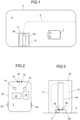
- Fig. 1 shows a schematic overview of a system controlling the robotic mower 2 by means of a guide wire 8 and/or by means of a boundary wire 4.
- the robotic mower 2 or as it also may be called a self-propelling lawnmower, is battery powered and needs to be recharged at regular intervals.
- the robotic mower 2 is during operation configured to move across an area A surrounded by the boundary wire 4.
- the boundary wire 4 may be configured in many different ways, such that it delimits the area A within which the robotic mower 2 is allowed to move.
- the boundary wire 4 is preferably provided under the ground in the lawn, such that is not visible, but may also be provided on or above the ground.
- the boundary wire 4 could be an ordinary copper wire of single-core type. There are of course also other options, which are well-known by a person skilled in the art, such as multi stranded wire types. As may be seen in Fig. 1 the boundary wire 4 makes a loop 4a in the charging station 11. This loop 4a is used to guide the robotic mower 2 into charging contact with the charging station 11.
- the system also comprises the charging station 11 mentioned above.
- the charging station itself 11 may be seen as the place where the charging of the robotic mower 2 takes place, and could for an example be provided with a charging station plate 24 onto which the robotic mower 2 is guided when performing docketing. Further, there is provided a charging station loop 10 at the charging station 11.
- the charging station loop 10 is entirely arranged at the charging station 11, more specifically, mounted on the charging station plate 24.
- a system according to the present disclosure may also comprise one or more guide wires 8.
- a guide wire 8 is a wire that the robotic mower 2 may follow when returning to the charging station 11, when exiting the charging station 11 to start a mowing cycle and/or to move along a way that is otherwise difficult to find.
- the robotic mower 2 may also be adapted to follow the boundary wire 4 back to the charging station 11 and/or to exit the charging station 11 to start a mowing cycle.
- the boundary wire 4, the charging station loop 10 and the one or more guide wires 8 are all connected to a signal generator which feeds each wire and loop with a, particularly wire-specific, current signal, in particular an Alternating Current, AC, signal, such that the robotic mower 2 may recognize which wire or loop it is detecting when it is within sensing distance.
- a signal generator which feeds each wire and loop with a, particularly wire-specific, current signal, in particular an Alternating Current, AC, signal, such that the robotic mower 2 may recognize which wire or loop it is detecting when it is within sensing distance.
- the robotic mower 2 may be adapted to detect magnetic fields of the different signal wires.
- the robotic mower 2 comprises a control unit 22, wheels 20, at least two sensors 12, 14, in particular two sensors 12, 14, optionally three or four sensors, and a battery 18.
- the sensors 12, 14 each are adapted to sense magnetic fields.
- the robotic mower 2 comprises exactly two sensors 12, 14.
- the control unit 22, which will be closer described in conjunction with Fig. 4 comprises a processor 80 for controlling the movement of the robotic mower 2.
- the sensors 12, 14 can sense a magnetic field that is generated in the boundary wire 4, the charging station loop 10 and/or the one or several guide wires 8.
- the signals of the different wires 4, 8 and wire loop 10 may be encoded differently.
- the sensed magnetic field, i.e. signal is decoded in the control unit 22 to determine from which loop or wire it was received.
- the robotic mower 2 further comprises charging connectors 16.
- the robotic mower 2 has a forward-rearward axis along which the robotic mower 2 moves when it drives straight ahead or straight backwards.
- the robotic mower 2 has a longitudinal extension in accordance with the forward-rearward axis.
- the two sensors 12, 14 are arranged at, e.g. fixed with respect to, a main body 34 of the robotic mower 2 displaced to one another in a direction orthogonal to the forward-rearward axis.
- the sensors 12, 14 are arranged in a front region of the robotic mower 2 and could be referred to as front sensors 12, 14.
- Two rear sensors may optionally be provided at the rear of the robotic mower 2 and arranged displaced to one another in a direction orthogonal to the forward-rearward axis.
- Fig. 3 shows an exemplary embodiment of the charging station 11.
- the charging station 11 comprises the charging station plate 24 at which the charging station loop 10, which can also be referred to as far-field loop, and the boundary wire loop 4a, which may also be referred to as near-field loop, are arranged.
- the charging station 11 further comprises the signal generator 6.
- the charging station 11 comprises charging connectors 26 which are arranged so as to be contacted by the charging connectors 16 of the robotic mower 2 when docking into the charging station 11.
- the charging connectors 26 are mounted on a tower 28 of the charging station 11.
- the control unit 22 comprises, as mentioned above, the processor 80 and a memory 82.
- the memory 82 may comprise a computer program 84 comprising computer program code, i.e. instructions.
- the computer program code is adapted to implement method steps performed by the robotic mower 2 when the code is executed on the processor 80.
- the control unit 22 further comprises an interface 86 for communication with the sensors 12, 14, and one or more motors that operate(s) the robotic mower 2, in particular a motor for driving a blade which will be described below with reference to Fig. 6 .
- the control unit 22 is adapted to receive, store and process signals from the sensors 12, 14.
- the processor 80 may comprise a single Central Processing Unit (CPU), or could comprise two or more processing units.
- the processor 80 may include general purpose microprocessors, instruction set processors and/or related chips sets and/or special purpose microprocessors such as Application Specific Integrated Circuits (ASICs), Field Programmable Gate Arrays (FPGAs) or Complex Programmable Logic Devices (CPLDs).
- ASICs Application Specific Integrated Circuits
- FPGAs Field Programmable Gate Arrays
- CPLDs Complex Programmable Logic Devices
- the processor 80 may also comprise a storage for caching purposes.
- Fig. 5 depicts the signal generator 6, which also comprises a processor 60 and a memory 62.
- the memory 62 may comprise a computer program 64 comprising computer program code, i.e. instructions.
- the computer program code is adapted to implement method steps performed by the signal generator 6 when the code is executed on the processor 60.
- the signal generator 6 further comprises an interface 66 for transmitting the generated, e.g. AC, signals to the boundary wire 4, charging station loop 10 and guide wire or wires 8, particularly as burst signals.
- at least one wire or wire loop 4, 8, 10, or all of the described wires 4, 8 and loop 10 may be fed with burst signals by the signal generator 6, wherein two consecutive bursts are spaced in time.
- the processor 60 may comprise a single Central Processing Unit (CPU), or could comprise two or more processing units.
- the processor 60 may include general purpose microprocessors, instruction set processors and/or related chips sets and/or special purpose microprocessors such as Application Specific Integrated Circuits (ASICs), Field Programmable Gate Arrays (FPGAs) or Complex Programmable Logic Devices (CPLDs).
- ASICs Application Specific Integrated Circuits
- FPGAs Field Programmable Gate Arrays
- CPLDs Complex Programmable Logic Devices
- the processor 60 may also comprise a storage for caching purposes.
- the robotic mower 2 comprises at least one blade 32 to cut the lawn, e.g., two, three or four blades 32.
- The, or each, blade 32 may be elongate, have the shape of a disc or other shapes.
- the robotic mower 2 comprises a cutting disc on which a plurality of blades, namely four, alternatively three or two, blades 32 are mounted.
- the blade(s) 32 is/are rotatable around a rotational axis R with respect to a main body 34 of the robotic mower 2.
- the blade 32 is rotatable with respect to the main body 34 of the robotic mower 2 by means of a motor 30, which is an electric motor in this example and supplied with energy from the battery 18.
- the cutting disc is rotatable by means of the motor 30 so as to rotate the blades 32 mounted to the cutting disc.
- the first and second sensors 12, 14 are arranged in the same distance to the rotational axis R.
- the first and second sensors 12, 14 are arranged in the same plane.
- an angle formed by the two sensors 12, 14 and the rotational axis R is 90 degrees, or 75 degrees, or 100 degrees, or within the range of 45 degrees to 150 degrees, particularly within the range of 75 to 100 degrees.
- the operation of the motor 30 creates time-varying electromagnetic fields that interfere with the signals emitted by a wire 4, 8 or loop 10 being in sensing distance. Further, also the blade(s) 32 may interfere with these signals due to its permittivity. The blade(s) 32 may optionally be made of a magnetic or magnetized material and interfere with said signals for this reason when rotating.
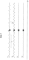
- Fig. 7 illustrates the amplitude of different signals S1, S2, S1', S2' versus time t and thus for a plurality of points in time.
- a first signal S1 detected by the first sensor 12 is shown as the uppermost signal.
- the second signal S2 from above is detected using the second sensor 14.
- the burst signal is detected both by the first and second sensors 12, 14 at the same time.
- the motor 30 and blade(s) 32 can also be referred to as active device interfering with the signals S1, S2 detectable by the sensors 12, 14. By rotating with a certain rotational speed, the motor 30 and/or blade(s) 32 are the source for a periodic signal component in the signals S1, S2 detected by the sensors 12, 14. By this, the signal bursts are altered and the quality of their reception is degraded.
- the robotic mower 2 is adapted to detect, by means of the sensors 12, 14, the signals S1, S2 including the burst signals from, e.g., the boundary wire 8 as signal source at different points in time, particularly continuously.
- the robotic mower 2 is further adapted to store data indicative for the detected signals S1, S2 in the memory 82, to compare signal amplitude values determined based on the data indicative for the signals S1, S2 stored in the memory 84 of three different points in time t1, t2, t3 with one another to differentiate the signal values by sorting them into a low signal value, an intermediate signal value and a high signal value, to subtract the intermediate signal value from a current signal value detected by means of the sensors 12, 14 to obtain at least one processed signal S1', S2' value and to control its operation based on the processed signal S1', S2' value.
- the control unit 22 determines the rotational speed of the blade(s) 32, e.g., as rotations per minute, RPM. By this, the interfering signal repetition rate is determined by the control unit 22 and known to the control unit 22.
- the control unit 22 calculates a first time offset T1 as the time for one complete revolution of the blade(s) 32, and a second time offset T2 as the time difference between the arrival of one blade 32 at the first sensor 12 and at the second sensor 14.
- the second time offset T2 may be approximately quarter revolution of the blades 32.
- the three signal values D1, D2, D3 are sorted by the control unit 22 with respect to their value.
- the intermediate value M among these is selected as being most likely free of any burst signal, so that it is suited as a baseline.
- a corresponding calculation may be performed using the second signal S2.
- the control unit 22 samples the sensor 12, 14 readings with a given sample rate, and over the time the above calculation of the processed signal S1' value is repeated for each sample at the respective current time T. For example, when the latest signal samples are stored in the memory 84, the oldest samples are removed from the memory 84.
- the control unit 22 may be adapted to store the signal data within a certain period of time. The result are the first and second processed signals S1', S2' shown in Fig. 7 .
- the robotic mower 2 is operated, particularly navigated. This allows a strongly improved precision of the operation. Further, it is possible to arrange the sensors 12, 14 closer to the motor 30 and blade 32. By this it is also possible to reduce the size of the robotic mower 2.
- Fig. 7 also shows the width of the first time offset T1 and the second time offset T2. It can be seen that the interfering signal component is periodic and repeats after one revolution of the blade 32 corresponding to the first time offset T1. Further, due to their displaced arrangement, the signals recorded by the two sensors 12, 14 are offset by the second time offset T2. In the example of Fig. 7 the second signal S2 is inverted with respect to the first signal S1 due to an inverted orientation of the second sensor 14 with respect to the first sensor 12. In this case the second signal S2 values may be multiplied by -1 in the above calculation. Alternatively, both sensors 12, 14 are arranged with the same orientation.
- the time offset between two consecutive burst signals from the boundary wire 4 is greater than the first time offset T1. That is, the wires 4, 8 and wire loop 11 are only active at a portion of the time, e.g., between 1% to 10% of the time, e.g., at about 4% of the time.
- the noise signals are continuously active while the motor 30 is active.
- the signal value D1, D2, D3 of one of the three points in time t1, t2, t3 may comprise a contribution of a burst signal.
- This one of the three signal values D1, D2, D3 most likely has the highest or lowest amplitude while the intermediate one of the three signal values D1, D2, D3 most likely has no contribution of a burst signal and therefore qualifies to remove the interference signal component.
- the first time offset T1 may be the time of an integer number of complete revolutions of the blade, e.g., 1, 2, 3 or more.
- T1 can generally be determined based the RPM of the blade 32 and T2 can generally be determined from the fixed relative arrangement of the sensors 12, 14 with respect to the rotational axis R.
- a signal of the first sensor 12 is cleaned up, e.g., an interference is removed, by finding a time-delayed copy of an interference on the signal of the second sensor 14, and subtracting it from the signal of the first sensor 12.
- a signal of the second sensor 14 may be cleaned up, e.g., an interference is removed, by finding a time-delayed copy of an interference on the signal of the first sensor 12, and subtracting it from the signal of the second sensor.
- the interference may be the same every revolution of the blade 32 or cutting disc.
- Fig. 8 shows a method for controlling an apparatus, e.g., the robotic mower 2 described above, comprising at least two sensors 12, 14, and an active device 30, 32 interfering with signals detectable by the at least two sensors 12, 14.
- the method comprises the following steps.
- Step S101 Detecting, by means of the at least two sensors 12, 14, signals S1, S2 at different points in time, the signals S1, S2 including burst signals from a signal source, e.g., the boundary wire 4.
- Step S102 Storing data indicative for the detected signals S1, S2 in a memory 82.
- a FIFO may be used.
- the active device 30, 32 may comprise a rotatable component, e.g., the blade 32, being rotatable about the rotational axis R, and the method optionally comprises step S103: Determining a rotational speed of the rotatable component. This may be done, e.g., using the detected signals S1, S2 and/or based on set points defined in the control unit 22.
- Step S104 Comparing signal values determined based on the data indicative for the signals S1, S2 stored in the memory 84 of three different points in time t1, t2, t3 with one another to sort the signal values into a low signal value, an intermediate signal value and a high signal value.
- the three different points in time t1, t2, t3 may be calculated based on the determined rotational speed and/or using the first time offset T1 and the second time offset T2.
- Step S105 Subtracting the intermediate signal value from a current signal value detected by means of at least one of the at least two sensors 12, 14 to obtain at least one processed signal S1', S2' value.
- Step S106 Controlling operation of the apparatus, e.g., the robotic mower 2, based on the processed signal S1', S2' value.
- steps S104 and S105 may be iteratively repeated, e.g., at a given sample rate, in particular steps S104 and S105.
- the computer program 84 of the control unit 22 may comprise instructions that, when executed by the processor 80 cause the robotic mower 2 to perform the above method.
Landscapes
- Engineering & Computer Science (AREA)
- Physics & Mathematics (AREA)
- Aviation & Aerospace Engineering (AREA)
- Radar, Positioning & Navigation (AREA)
- Remote Sensing (AREA)
- General Physics & Mathematics (AREA)
- Automation & Control Theory (AREA)
- Electromagnetism (AREA)
- Life Sciences & Earth Sciences (AREA)
- Environmental Sciences (AREA)
- Harvester Elements (AREA)
Claims (10)
- Verfahren zum Steuern einer Einrichtung (2), die mindestens zwei Sensoren (12, 14) und eine aktive Vorrichtung (30, 32) umfasst, die mit von den mindestens zwei Sensoren (12, 14) detektierbaren Signalen interferiert, wobei die aktive Vorrichtung (30, 32) eine oder mehrere drehbare Komponenten (32) umfasst, die um eine Drehachse (R) drehbar sind, und wobei die aktive Vorrichtung (30, 32) ein periodisches Interferenzsignal erzeugt, wobei das Verfahren umfasst:- Detektieren (S101) anhand der mindestens zwei Sensoren (12, 14) zweier entsprechender Signale (S1, S2), wobei die Signale (S1, S2) Burst-Signale von einer Signalquelle (4, 8, 10) beinhalten,- Speichern (S102) von Daten, die bezeichnend für die mindestens zwei detektierten Signale (S1, S2) sind, in einem Speicher (82),dadurch gekennzeichnet, dass das Verfahren weiter umfasst:- Vergleichen (S104) von Signalwerten, die basierend auf den Daten bestimmt werden, die bezeichnend für die mindestens zwei detektierten Signale (S1, S2) sind, die im Speicher (84) zu drei verschiedenen Zeitpunkten gespeichert wurden, miteinander, um die Signalwerte in einen niedrigen Signalwert, einen mittleren Signalwert und einen hohen Signalwert zu unterscheiden,wobei die drei unterschiedlichen Zeitpunkte einen ersten Zeitpunkt mit einem ersten Zeitversatz (T1) vor einer aktuellen Zeit, einen zweiten Zeitpunkt mit einem zweiten Zeitversatz (T2) vor der aktuellen Zeit und einen dritten Zeitpunkt mit einem dritten Zeitversatz (T3) vor der aktuellen Zeit umfassen,wobei die mindestens zwei Sensoren (12, 14) einen ersten Sensor (12) und einen zweiten Sensor (14) umfassen und der erste Zeitversatz (T1) die Zeit einer ganzzahligen Anzahl der vollständigen Umdrehungen der einen oder mehreren drehbaren Komponenten (32) um die Drehachse (R) ist, und der zweite Zeitversatz (T2) die Zeit ist, um einen Abschnitt der drehbaren Komponente (32) von der Position am nächsten zum ersten Sensor (12) zur Position am nächsten zum zweiten Sensor (14) zu drehen, und der dritte Zeitversatz (T3) gleich dem ersten Zeitversatz (T1) plus dem zweiten Zeitversatz (T2) ist,wobei die verglichenen Signalwerte einen zum ersten Zeitpunkt bestimmten ersten Signalwert, einen zum zweiten Zeitpunkt bestimmten zweiten Signalwert und einen zum dritten Zeitpunkt bestimmten dritten Signalwert umfassen,wobei der erste Signalwert unter Verwendung des ersten Sensors (12) bestimmt wird, der zweite Signalwert unter Verwendung des zweiten Sensors (14) bestimmt wird und der dritte Signalwert unter Verwendung des zweiten Sensors (14) bestimmt wird,- Subtrahieren (S105) des Zwischensignalwerts von einem anhand mindestens eines der mindestens zwei Sensoren (12, 14) detektierten aktuellen Signalwert, um mindestens ein verarbeitetes Signal (S1', S2') zu erhalten, und- Steuern (S106) des Betriebs der Einrichtung (2) basierend auf dem verarbeiteten Signal (S1', S2').
- Verfahren nach Anspruch 1, das weiter Bestimmen (S103) einer Drehgeschwindigkeit der drehbaren Komponente (32) umfasst.
- Verfahren nach Anspruch 2, wobei die drehbare Komponente (32) eine Schaufel ist und die aktive Vorrichtung (30, 32) einen Motor (30) umfasst, um die Schaufel zu drehen.
- Verfahren nach Anspruch 2 oder 3, das weiter Bestimmen des ersten Zeitversatzes (T1) und des zweiten Zeitversatzes (T2), der kleiner als der erste Zeitversatz (T1) ist, umfasst.
- Einrichtung (2), die mindestens zwei Sensoren (12, 14) und eine aktive Vorrichtung (30, 32) umfasst, die mit von den mindestens zwei Sensoren (12, 14) detektierbaren Signalen interferiert, wobei die aktive Vorrichtung (30, 32) eine oder mehrere drehbare Komponenten (32) umfasst, die um eine Drehachse (R) drehbar sind, und wobei die aktive Vorrichtung (30, 32) ein periodisches Interferenzsignal erzeugt, wobei die Einrichtung (2) angepasst ist, um:- anhand der mindestens zwei Sensoren (12, 14) zwei entsprechende Signale (S1, S2) zu detektieren, wobei die Signale (S1, S2) Burst-Signale von einer Signalquelle (4, 8, 10) beinhalten,- Daten, die bezeichnend für die mindestens zwei detektierten Signale (S1, S2) sind, in einem Speicher (82) zu speichern,dadurch gekennzeichnet, dass die Einrichtung (2) weiter angepasst ist, um:- Signalwerte, die basierend auf den Daten bestimmt werden, die bezeichnend für die mindestens zwei detektierten Signale (S1, S2) sind, die im Speicher (84) zu drei verschiedenen Zeitpunkten gespeichert wurden, miteinander zu vergleichen, um die Signalwerte in einen niedrigen Signalwert, einen mittleren Signalwert und einen hohen Signalwert zu unterscheiden,wobei die drei unterschiedlichen Zeitpunkte einen ersten Zeitpunkt mit einem ersten Zeitversatz (T1) vor einer aktuellen Zeit, einen zweiten Zeitpunkt mit einem zweiten Zeitversatz (T2) vor der aktuellen Zeit und einen dritten Zeitpunkt mit einem dritten Zeitversatz (T3) vor der aktuellen Zeit umfassen,wobei die mindestens zwei Sensoren (12, 14) einen ersten Sensor (12) und einen zweiten Sensor (14) umfassen und der erste Zeitversatz (T1) die Zeit einer ganzzahligen Anzahl der vollständigen Umdrehungen der einen oder mehreren drehbaren Komponenten (32) um die Drehachse (R) ist, und der zweite Zeitversatz (T2) die Zeit ist, um einen Abschnitt der drehbaren Komponente (32) von der Position am nächsten zum ersten Sensor (12) zur Position am nächsten zum zweiten Sensor (14) zu drehen, und der dritte Zeitversatz (T3) gleich dem ersten Zeitversatz (T1) plus dem zweiten Zeitversatz (T2) ist,wobei die verglichenen Signalwerte einen zum ersten Zeitpunkt bestimmten ersten Signalwert, einen zum zweiten Zeitpunkt bestimmten zweiten Signalwert und einen zum dritten Zeitpunkt bestimmten dritten Signalwert umfassen,wobei der erste Signalwert unter Verwendung des ersten Sensors (12) bestimmt wird, der zweite Signalwert unter Verwendung des zweiten Sensors (14) bestimmt wird und der dritte Signalwert unter Verwendung des zweiten Sensors (14) bestimmt wird,- den Zwischensignalwert von einem anhand mindestens eines der mindestens zwei Sensoren (12, 14) detektierten aktuellen Signalwert zu subtrahieren, um mindestens einen verarbeiteten Signalwert (S1', S2') zu erhalten, und- seinen Betrieb basierend auf dem verarbeiteten Signal (S1', S2') zu steuern.
- Einrichtung (2) nach Anspruch 5, wobei jeder des ersten und zweiten Sensors (12, 14) angepasst ist, um ein Magnetfeld zu erfassen.
- Einrichtung (2) nach Anspruch 6, wobei die Einrichtung (2) einen Hauptkörper (34) umfasst, und der erste Sensor (12) und der zweite Sensor (14) versetzt zueinander am Hauptkörper (34) angeordnet sind.
- Einrichtung (2) nach Anspruch 7, wobei der erste und zweite Sensor (12, 14) angeordnet sind, sodass die Drehachse (R) und der erste und zweite Sensor (12, 14) einen Viertelkreis oder weniger als einen Viertelkreis eines Kreises um die Drehachse (R) definieren.
- Einrichtung (2) nach einem der Ansprüche 5 bis 8, wobei die aktive Vorrichtung einen Motor (30) und eine durch den Motor (30) drehbare Schaufel (32) umfasst.
- Einrichtung (2) nach Anspruch 9, wobei die Schaufel (32) ein magnetisches Material umfasst.
Applications Claiming Priority (1)
| Application Number | Priority Date | Filing Date | Title |
|---|---|---|---|
| PCT/CN2020/136446 WO2022126364A1 (en) | 2020-12-15 | 2020-12-15 | Signal interference rejection method and apparatus |
Publications (4)
| Publication Number | Publication Date |
|---|---|
| EP4264389A1 EP4264389A1 (de) | 2023-10-25 |
| EP4264389A4 EP4264389A4 (de) | 2023-11-29 |
| EP4264389C0 EP4264389C0 (de) | 2025-01-29 |
| EP4264389B1 true EP4264389B1 (de) | 2025-01-29 |
Family
ID=82059827
Family Applications (1)
| Application Number | Title | Priority Date | Filing Date |
|---|---|---|---|
| EP20965382.3A Active EP4264389B1 (de) | 2020-12-15 | 2020-12-15 | Verfahren und vorrichtung zur unterdrückung von signalinterferenzen |
Country Status (4)
| Country | Link |
|---|---|
| US (1) | US12510895B2 (de) |
| EP (1) | EP4264389B1 (de) |
| CN (1) | CN116547621B (de) |
| WO (1) | WO2022126364A1 (de) |
Family Cites Families (18)
| Publication number | Priority date | Publication date | Assignee | Title |
|---|---|---|---|---|
| US4602247A (en) * | 1983-02-18 | 1986-07-22 | Nissan Motor Company, Limited | Method and system for detecting driver fatigue including differentiation of effects of rest periods |
| US6351666B1 (en) * | 1998-02-27 | 2002-02-26 | Biofield Corp. | Method and apparatus for sensing and processing biopotentials |
| US20060221061A1 (en) * | 2005-03-31 | 2006-10-05 | Tyco Electronic Corporation | Touch sensor and control with random pulse spacing |
| AU2007327710B2 (en) * | 2007-05-30 | 2010-04-22 | Mitsubishi Electric Corporation | Brake control device for electric vehicle |
| JP5117284B2 (ja) * | 2008-06-05 | 2013-01-16 | 株式会社東芝 | Fm復調器およびfm受信機 |
| DE102010028251A1 (de) * | 2010-04-27 | 2011-10-27 | Robert Bosch Gmbh | Verfahren zum Erkennen eines Arbeitsbereichs sowie ein Gerät hierfür |
| US8392044B2 (en) * | 2010-07-28 | 2013-03-05 | Deere & Company | Robotic mower boundary sensing system |
| DE102012017869B4 (de) * | 2012-09-04 | 2020-01-16 | Hagenuk KMT Kabelmeßtechnik GmbH | Vorrichtung zur Reduzierung von Störeinflüssen bei der Mantelfehlerortung und Mantelfehlerortungsvorrichtung |
| EP2741160B1 (de) * | 2012-12-07 | 2016-10-12 | Viking GmbH | Verfahren zur Steuerung eines selbstfahrenden Rasenmähers |
| CN103941600B (zh) * | 2013-01-22 | 2016-12-28 | 苏州宝时得电动工具有限公司 | 自动工作系统 |
| US9072219B2 (en) * | 2013-06-20 | 2015-07-07 | Deere & Company | Robotic mower navigation system |
| US9146850B2 (en) * | 2013-08-01 | 2015-09-29 | SMART Storage Systems, Inc. | Data storage system with dynamic read threshold mechanism and method of operation thereof |
| EP3156873B2 (de) * | 2015-10-15 | 2023-04-05 | Honda Research Institute Europe GmbH | Autonomes fahrzeug mit verbesserter simultaner ortung und kartierungsfunktion |
| US20170263426A1 (en) * | 2016-03-10 | 2017-09-14 | Leco Corporation | Dynamic Baseline Adjuster |
| WO2019127568A1 (en) * | 2017-12-30 | 2019-07-04 | Changzhou Globe Co., Ltd. | System and method for controlling a self-propelling lawnmower |
| US11474524B2 (en) * | 2018-03-30 | 2022-10-18 | Globe (jiangsu) Co., Ltd. | Robotic mower and method for controlling a robotic mower |
| CN109091140A (zh) * | 2018-07-06 | 2018-12-28 | 四川斐讯信息技术有限公司 | 一种心电信号r波检测方法及系统 |
| SE542918C2 (en) * | 2019-01-15 | 2020-09-15 | Husqvarna Ab | Robotic tool with boundary wire loop |
-
2020
- 2020-12-15 EP EP20965382.3A patent/EP4264389B1/de active Active
- 2020-12-15 CN CN202080107190.0A patent/CN116547621B/zh active Active
- 2020-12-15 WO PCT/CN2020/136446 patent/WO2022126364A1/en not_active Ceased
-
2023
- 2023-05-06 US US18/313,315 patent/US12510895B2/en active Active
Also Published As
| Publication number | Publication date |
|---|---|
| EP4264389C0 (de) | 2025-01-29 |
| WO2022126364A1 (en) | 2022-06-23 |
| CN116547621B (zh) | 2025-02-07 |
| US12510895B2 (en) | 2025-12-30 |
| US20230273619A1 (en) | 2023-08-31 |
| EP4264389A4 (de) | 2023-11-29 |
| CN116547621A (zh) | 2023-08-04 |
| EP4264389A1 (de) | 2023-10-25 |
Similar Documents
| Publication | Publication Date | Title |
|---|---|---|
| AU2003244284B2 (en) | Electronic directing system | |
| EP3599813B1 (de) | Robotermäher und verfahren zur steuerung eines robotermähers | |
| US11415998B2 (en) | System and method for docking a robotic mower | |
| EP3746857B1 (de) | System und verfahren zum navigieren eines robotischen rasenmähers in eine andockposition | |
| US9268331B2 (en) | Domestic robotic system and robot therefor | |
| CN110506246B (zh) | 包括提升/碰撞检测装置的机器人作业工具及用于机器人作业工具的方法 | |
| EP2829937B1 (de) | Roboter-Arbeitsgerät für einen begrenzten Arbeitsbereich | |
| JPH09509559A (ja) | 自己内蔵型移動ロボット用電力供給装置 | |
| US12535820B2 (en) | Navigating a robotic mower with dead reckoning | |
| EP3589111A1 (de) | Verbesserte reduzierung von radspuren für roboterrasenmäher | |
| CN115605818B (zh) | 通过导线导航机器人割草机的方法 | |
| CN108427410A (zh) | 自移动设备 | |
| WO2020148138A1 (en) | Robotic tool | |
| EP4264389B1 (de) | Verfahren und vorrichtung zur unterdrückung von signalinterferenzen | |
| US12464978B2 (en) | Navigating a robotic mower along a wire | |
| CN116322299A (zh) | 通过引导线导航机器人割草机 | |
| CN114510026B (zh) | 一种边界线信号检测方法及自动行走设备 | |
| CN112433521B (zh) | 一种自行走装置的控制方法、自行走装置及系统 |
Legal Events
| Date | Code | Title | Description |
|---|---|---|---|
| STAA | Information on the status of an ep patent application or granted ep patent |
Free format text: STATUS: THE INTERNATIONAL PUBLICATION HAS BEEN MADE |
|
| PUAI | Public reference made under article 153(3) epc to a published international application that has entered the european phase |
Free format text: ORIGINAL CODE: 0009012 |
|
| STAA | Information on the status of an ep patent application or granted ep patent |
Free format text: STATUS: REQUEST FOR EXAMINATION WAS MADE |
|
| 17P | Request for examination filed |
Effective date: 20230706 |
|
| AK | Designated contracting states |
Kind code of ref document: A1 Designated state(s): AL AT BE BG CH CY CZ DE DK EE ES FI FR GB GR HR HU IE IS IT LI LT LU LV MC MK MT NL NO PL PT RO RS SE SI SK SM TR |
|
| A4 | Supplementary search report drawn up and despatched |
Effective date: 20231102 |
|
| RIC1 | Information provided on ipc code assigned before grant |
Ipc: G05D 1/02 20200101AFI20231026BHEP |
|
| DAV | Request for validation of the european patent (deleted) | ||
| DAX | Request for extension of the european patent (deleted) | ||
| REG | Reference to a national code |
Ref country code: DE Free format text: PREVIOUS MAIN CLASS: G05D0001020000 Ref country code: DE Ref legal event code: R079 Ref document number: 602020045700 Country of ref document: DE Free format text: PREVIOUS MAIN CLASS: G05D0001020000 Ipc: G05D0001000000 |
|
| RIC1 | Information provided on ipc code assigned before grant |
Ipc: G05D 1/00 20060101AFI20240722BHEP |
|
| GRAP | Despatch of communication of intention to grant a patent |
Free format text: ORIGINAL CODE: EPIDOSNIGR1 |
|
| STAA | Information on the status of an ep patent application or granted ep patent |
Free format text: STATUS: GRANT OF PATENT IS INTENDED |
|
| INTG | Intention to grant announced |
Effective date: 20241011 |
|
| GRAS | Grant fee paid |
Free format text: ORIGINAL CODE: EPIDOSNIGR3 |
|
| GRAA | (expected) grant |
Free format text: ORIGINAL CODE: 0009210 |
|
| STAA | Information on the status of an ep patent application or granted ep patent |
Free format text: STATUS: THE PATENT HAS BEEN GRANTED |
|
| AK | Designated contracting states |
Kind code of ref document: B1 Designated state(s): AL AT BE BG CH CY CZ DE DK EE ES FI FR GB GR HR HU IE IS IT LI LT LU LV MC MK MT NL NO PL PT RO RS SE SI SK SM TR |
|
| REG | Reference to a national code |
Ref country code: GB Ref legal event code: FG4D |
|
| REG | Reference to a national code |
Ref country code: CH Ref legal event code: EP |
|
| REG | Reference to a national code |
Ref country code: DE Ref legal event code: R096 Ref document number: 602020045700 Country of ref document: DE |
|
| REG | Reference to a national code |
Ref country code: IE Ref legal event code: FG4D |
|
| U01 | Request for unitary effect filed |
Effective date: 20250129 |
|
| U07 | Unitary effect registered |
Designated state(s): AT BE BG DE DK EE FI FR IT LT LU LV MT NL PT RO SE SI Effective date: 20250210 |
|
| PG25 | Lapsed in a contracting state [announced via postgrant information from national office to epo] |
Ref country code: RS Free format text: LAPSE BECAUSE OF FAILURE TO SUBMIT A TRANSLATION OF THE DESCRIPTION OR TO PAY THE FEE WITHIN THE PRESCRIBED TIME-LIMIT Effective date: 20250429 |
|
| PG25 | Lapsed in a contracting state [announced via postgrant information from national office to epo] |
Ref country code: PL Free format text: LAPSE BECAUSE OF FAILURE TO SUBMIT A TRANSLATION OF THE DESCRIPTION OR TO PAY THE FEE WITHIN THE PRESCRIBED TIME-LIMIT Effective date: 20250129 |
|
| PG25 | Lapsed in a contracting state [announced via postgrant information from national office to epo] |
Ref country code: ES Free format text: LAPSE BECAUSE OF FAILURE TO SUBMIT A TRANSLATION OF THE DESCRIPTION OR TO PAY THE FEE WITHIN THE PRESCRIBED TIME-LIMIT Effective date: 20250129 |
|
| PG25 | Lapsed in a contracting state [announced via postgrant information from national office to epo] |
Ref country code: IS Free format text: LAPSE BECAUSE OF FAILURE TO SUBMIT A TRANSLATION OF THE DESCRIPTION OR TO PAY THE FEE WITHIN THE PRESCRIBED TIME-LIMIT Effective date: 20250529 Ref country code: NO Free format text: LAPSE BECAUSE OF FAILURE TO SUBMIT A TRANSLATION OF THE DESCRIPTION OR TO PAY THE FEE WITHIN THE PRESCRIBED TIME-LIMIT Effective date: 20250429 |
|
| PG25 | Lapsed in a contracting state [announced via postgrant information from national office to epo] |
Ref country code: HR Free format text: LAPSE BECAUSE OF FAILURE TO SUBMIT A TRANSLATION OF THE DESCRIPTION OR TO PAY THE FEE WITHIN THE PRESCRIBED TIME-LIMIT Effective date: 20250129 |
|
| PG25 | Lapsed in a contracting state [announced via postgrant information from national office to epo] |
Ref country code: GR Free format text: LAPSE BECAUSE OF FAILURE TO SUBMIT A TRANSLATION OF THE DESCRIPTION OR TO PAY THE FEE WITHIN THE PRESCRIBED TIME-LIMIT Effective date: 20250430 |
|
| PG25 | Lapsed in a contracting state [announced via postgrant information from national office to epo] |
Ref country code: SM Free format text: LAPSE BECAUSE OF FAILURE TO SUBMIT A TRANSLATION OF THE DESCRIPTION OR TO PAY THE FEE WITHIN THE PRESCRIBED TIME-LIMIT Effective date: 20250129 |
|
| PG25 | Lapsed in a contracting state [announced via postgrant information from national office to epo] |
Ref country code: CZ Free format text: LAPSE BECAUSE OF FAILURE TO SUBMIT A TRANSLATION OF THE DESCRIPTION OR TO PAY THE FEE WITHIN THE PRESCRIBED TIME-LIMIT Effective date: 20250129 |
|
| PG25 | Lapsed in a contracting state [announced via postgrant information from national office to epo] |
Ref country code: SK Free format text: LAPSE BECAUSE OF FAILURE TO SUBMIT A TRANSLATION OF THE DESCRIPTION OR TO PAY THE FEE WITHIN THE PRESCRIBED TIME-LIMIT Effective date: 20250129 |
|
| PLBE | No opposition filed within time limit |
Free format text: ORIGINAL CODE: 0009261 |
|
| STAA | Information on the status of an ep patent application or granted ep patent |
Free format text: STATUS: NO OPPOSITION FILED WITHIN TIME LIMIT |
|
| 26N | No opposition filed |
Effective date: 20251030 |
|
| U20 | Renewal fee for the european patent with unitary effect paid |
Year of fee payment: 6 Effective date: 20251222 |