EP4263945B1 - Towable structure for the treatement of road surfaces - Google Patents
Towable structure for the treatement of road surfaces Download PDFInfo
- Publication number
- EP4263945B1 EP4263945B1 EP21839912.9A EP21839912A EP4263945B1 EP 4263945 B1 EP4263945 B1 EP 4263945B1 EP 21839912 A EP21839912 A EP 21839912A EP 4263945 B1 EP4263945 B1 EP 4263945B1
- Authority
- EP
- European Patent Office
- Prior art keywords
- wheels
- towable structure
- towable
- group
- locking
- Prior art date
- Legal status (The legal status is an assumption and is not a legal conclusion. Google has not performed a legal analysis and makes no representation as to the accuracy of the status listed.)
- Active
Links
Images










Classifications
-
- E—FIXED CONSTRUCTIONS
- E01—CONSTRUCTION OF ROADS, RAILWAYS, OR BRIDGES
- E01C—CONSTRUCTION OF, OR SURFACES FOR, ROADS, SPORTS GROUNDS, OR THE LIKE; MACHINES OR AUXILIARY TOOLS FOR CONSTRUCTION OR REPAIR
- E01C23/00—Auxiliary devices or arrangements for constructing, repairing, reconditioning, or taking-up road or like surfaces
- E01C23/06—Devices or arrangements for working the finished surface; Devices for repairing or reconditioning the surface of damaged paving; Recycling in place or on the road
- E01C23/08—Devices or arrangements for working the finished surface; Devices for repairing or reconditioning the surface of damaged paving; Recycling in place or on the road for roughening or patterning; for removing the surface down to a predetermined depth high spots or material bonded to the surface, e.g. markings; for maintaining earth roads, clay courts or like surfaces by means of surface working tools, e.g. scarifiers, levelling blades
- E01C23/082—Devices or arrangements for working the finished surface; Devices for repairing or reconditioning the surface of damaged paving; Recycling in place or on the road for roughening or patterning; for removing the surface down to a predetermined depth high spots or material bonded to the surface, e.g. markings; for maintaining earth roads, clay courts or like surfaces by means of surface working tools, e.g. scarifiers, levelling blades using non-powered tools
Definitions
- the present invention refers to a towable structure, in particular a trailer, for the treatment of road surfaces, in particular asphalted surfaces.
- the present invention finds application within the sector of the construction and maintenance of tyre test tracks.
- one solution that has been adopted to alleviate the problem in relation to the periodic resurfacing of tracks is to use a trolley, pulled by a vehicle (for example. a tractor), and equipped with a plurality of locked tyres, i.e., not free to rotate around the axis thereof.
- the trolley is therefore equipped with a mechanism that makes it possible for the tyres to be rotated at such an angle that a new portion of tread faces the asphalted surface.
- Such a rotation operation must however be performed manually, wheel by wheel. This involves a series of manual processes that slow down the surface maintenance operation and therefore the productivity and efficiency of the treatment process.
- EP 0 529 544 B1 discloses a wheeled towable structure comprising the features of the preamble of independent claim 1.
- one object of the present invention is to speed up those operations necessary for the rotation and locking of the tyres so as to render the entire treatment process more continuous, faster, and therefore more efficient.
- a possible embodiment of a towable wheeled structure 1 comprises a frame 2 on which a plurality of groups of wheels 3 are mounted.
- Each group 3 comprises one or more rubber wheels 4, equipped with tyres, and mounted so at to rotate at a respective wheel axis A.
- each group of wheels 3 comprises two coaxial, paired rubber wheels 4.
- the towable structure 1 comprises means 5, 5', 6, 6', 7 for locking the rotation of the wheels 4 of each group of wheels 3 at a plurality of predetermined angular locking positions.
- the structure provides means for actuating the means for locking the rotation of the rubber wheels 4, configured in such a way as to allow the wheels 4 of each group to rotate from one locking position to another, during the operation of said towable structure.
- a towable structure 11 further comprises a pair of maneuvering wheels 14, connected to the frame 2 by means of an articulated mechanism 20 which, when operated, allows for the positioning of the maneuvering wheels 14 in at least two positions.
- a first treatment position ( FIG. 5A ) the maneuvering wheels 14 are raised from the ground, and the rubber wheels 4 are therefore in contact with the ground.
- a second maneuvering position ( FIG. 5B )
- the maneuvering wheels are in contact with the ground, whilst the rubber wheels 4 are raised from the ground.
- the maneuvering wheels 14 are mounted idling upon the respective axes thereof. In this second maneuvering position, therefore, the structure 11 can be more easily towed and maneuvered upon the maneuvering wheels 14, without the rubber wheels 4, which are usually locked in rotation, offering resistance to towing.
- the structure 1, 11 can advantageously comprise - as shown in figure 6 - a plurality of hydraulic jacks 30 for lifting the structure itself, so that the rubber wheels 4 are detached from the ground.
- This is particularly useful and advantageous, for example, in order to be able to easily replace the tyres of the rubber wheels 4, and/or in order to perform other maintenance operations upon the structure and/or upon the group of wheels 3.
- the number and arrangement of the group of wheels 3 can be chosen on the basis of the sizing of the structure and on the basis of the treatment coverage to be obtained.
- the groups of wheels 3 are arranged upon six axes A, parallel to each other and orthogonal to a towing direction T of the structure 1, 11.
- the group of wheels 3 are distributed on each of said six parallel axles A, such that the footprint of the rubber wheels 4 of groups on different axes partially overlaps to fully cover the overall gauge S of the towable structure 1, 11.
- the term overall gauge S refers to the distance S between the outer faces of the two outermost rubber wheels 4, along a direction orthogonal to the towing direction T. This arrangement is exemplified in figures 7A and 7B .
- eight groups of wheels 3 are envisaged, arranged staggered as described above, thus making it possible to cover an overall gauge of about 3 meters.
- the following figures 8 and 9 show a group of wheels 3, respectively in perspective and exploded view.
- the rubber wheels 4 of each group of wheels 3 are rotationally integral therebetween, mounted on the common wheel axis A.
- the group of wheels 3 is mounted on a small frame 8 that is rendered integral to the frame 2 of the towable structure 1, 11.
- the means for locking the rotation of the wheels 4 comprise a pair of flanges 5, 5', coaxially therebetween, and mounted in such a way as to rotate integrally around a flange axis F.
- the flanges 5, 5' are equipped with a plurality of slots that are denoted respectively by the numbers 9 and 9' in the figures.
- the locking means also comprise a pair of pins 6, 6', integral with the frame 8, and adapted to interfere, when operated, each with the slots 9, 9' of one of the flanges 5, 5'.
- the mechanism for locking the rotation of the wheels 4, the operation thereof will be described in greater detail below, has the already anticipated function of making it possible to lock the rotation of the wheels 4 of each group of wheels 3 at a plurality of predetermined angular locking positions.
- the locking means can be operated in such a way as to allow for the rotation of the wheels 4 of each group from one locking position to another, during the operation of said towable structure, without interrupting the road surface treatment operations.
- FIGS. 10 and 11 show a tyre of the group of wheels 3, whereupon, purely by way of example and for the sole purposes of this description, indications are given in relation to possible sectors of a tyre and corresponding to as many predetermined positions. In the example, there are twelve positions, numbered from '1' to '12', each therefore corresponding to twelve angular sectors 40, each of 30°.
- the slots 9, 9' are made at the peripheral circumference of each flange 5, 5', equally distributed along such a circumference.
- the slots 9, 9' all have the same length P along the circumference.
- each point of correspondence between the slots 9, 9' defines a corresponding predetermined position.
- figures 12A and 12B show the two flanges 5, 5', each thereof envisages six only (respectively indicated by 9 and 9') equally angularly spaced therebetween by 60°.
- the two flanges 5, 5' are mounted out of phase as shown in the figure, in such a way that the points of correspondence of the respective slots determine the twelve predetermined positions (again numbered from' 1 'to' 12 ') corresponding to the twelve tyres sectors.
- Figure 12C shows the two flanges 5, 5' superimposed, in partial transparency, in order to clearly show the points of correspondence of the slots 9, 9' and therefore the twelve predetermined positions.
- the rotational blocking occurs by means of two pins 6, 6' which, when actuated, interfere respectively with one of the slots 9, 9' of the flanges 5, 5', thereby causing it to be blocked in rotation.
- the actuation of the pins is preferably performed by the actuation means which comprise a hydraulic actuation mechanism for the pins.
- the hydraulic actuation component of the pins is within the reach of a person skilled in the art who will be able to choose the correct hydraulic actuators and size the circuit appropriately, without having to provide the details thereof herein.
- the hydraulic force for supplying these components can, for example, be taken from a tractor that pulls the structure, by means of a power take-off shaft thereof.
- Figure 14A shows the pin 6' which interferes, considering the direction of rotation R of the parts indicated in the figure, with one end of a slot 9' of the flange 5'. This interference evidently blocks the flange 5' in rotation. Insofar as the flange 5' is integral in rotation with the wheels 4, the wheels 4 are also blocked due to such interference at the predetermined position corresponding to the sector 40 denoted by '12' on the tyre.
- the pin 6 is not operational and does not perform any function and therefore can - as in the figure - be retracted without interfering with the corresponding slot 9 of the flange 5.
- the following figure 14B shows a transition step, between one position and another.
- the two pins 6 and 6' reverse the function and position thereof.
- the pin 6' retracts and relinquishes the interference and locking function, whilst the pin 6 extends and interferes with the slot 9 of the flange 5.
Landscapes
- Engineering & Computer Science (AREA)
- Mining & Mineral Resources (AREA)
- Architecture (AREA)
- Civil Engineering (AREA)
- Structural Engineering (AREA)
- Tires In General (AREA)
- Soil Working Implements (AREA)
- Handcart (AREA)
Description
- The present invention refers to a towable structure, in particular a trailer, for the treatment of road surfaces, in particular asphalted surfaces.
- The present invention finds application within the sector of the construction and maintenance of tyre test tracks.
- It is well known that, due to operational wear, such tracks must be periodically maintained, and often resurfaced.
- However, following a resurfacing process, the roughness characteristics of the surface are evidently altered, often to the point that these are no longer such as to guarantee compliance with the regulations for the sector, and at the same time, no longer such as to ensure an adequate level of adherence.
- In fact, it is known, that tests performed on tyres must be carried out under standardized conditions with respect to many parameters, including the coefficients of adhesion and surface roughness. This is in order to render all of the tests performed comparable and similar therebetween, even if performed at different times and/or in different places.
- The problem of maintaining test tracks in such a way that they are constantly compliant with the regulations is therefore strong felt.
- At present, one solution that has been adopted to alleviate the problem in relation to the periodic resurfacing of tracks, is to use a trolley, pulled by a vehicle (for example. a tractor), and equipped with a plurality of locked tyres, i.e., not free to rotate around the axis thereof.
- The sliding of these tyres upon the road surface, typically asphalted, leads to wear, and the rubber that detaches therefrom adheres to the road surface thereby improving the characteristics thereof in terms of grip and roughness, thus preserving a condition of compliance with the test regulations for longer.
- Such a system has the obvious drawback however that the tyres, in the area of contact with the asphalt, undergo severe wear, until reaching the point wherein a flat-spot is formed on the tread.
- The trolley is therefore equipped with a mechanism that makes it possible for the tyres to be rotated at such an angle that a new portion of tread faces the asphalted surface. Such a rotation operation must however be performed manually, wheel by wheel. This involves a series of manual processes that slow down the surface maintenance operation and therefore the productivity and efficiency of the treatment process. In particular, in order to be able to adjust the position of the wheels every time, it is necessary to:
- interrupt the treatment;
- manually lift the trolley;
- remove the tyre carrier axles;
- rotate the same by one step, and
- refit.
- These operations are then repeated for each tyre or tyre carrier axle of the trolley.
-
EP 0 529 544 B1independent claim 1. - The purpose of the present invention is, therefore, to solve those problems left unresolved by the prior art, by providing a towable structure as defined in
claim 1. Further characteristics of the present invention are defined in the corresponding dependent claims. - In particular, one object of the present invention is to speed up those operations necessary for the rotation and locking of the tyres so as to render the entire treatment process more continuous, faster, and therefore more efficient.
- Other clear advantages over the prior art, together with the characteristics and usages of the present invention, will become clear from the following detailed description of the preferred embodiments thereof, given purely by way of a non-limiting example.
- Reference will be made to the drawings in the attached figures, wherein:
-
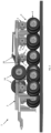
Figure 1 is a perspective view of a towable structure according to a first embodiment of the present invention; -
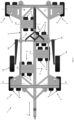
Figure 2 is a top view of the towable structure offigure 1 ; -
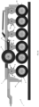
Figure 3 is a perspective view of a towable structure according to a second embodiment of the present invention; -
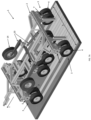
Figure 4 is a top view of the towable structure offigure 3 ; -
Figures 5A and5B show a structure according to the invention in two different possible configurations; -
Figure 6 is a side view of a structure according to the invention, that shows the presence of lifting jacks; -
Figures 7A and7B show the extent of the road surface treatment action; -
Figure 8 is a perspective view of one of the groups of wheel; -
Figure 9 is an exploded view of the group of wheels offigure 5 ; -
Figure 10 is a perspective view of a group of wheels, wherein, by way of example, the subdivision of the tyre into sectors is indicated; -
Figure 11 is a front view of a tyre wherein, by way of example, the subdivision into sectors is indicated; -
Figures 12A to 12B show the two flanges of a group of wheels according to the invention; -
Figure 12C shows the two flanges of a superimposed group of wheels, in partial transparency; -
Figure 13 shows the means for locking the rubber wheels of a group of wheels; and -
Figures 14A to 14C show the modality according to which the controlled rotation from one sector to an adjacent sector takes place. - The present invention will be described below with reference to the above figures. Referring first to
figures 1 and2 , a possible embodiment of a towablewheeled structure 1, according to the present invention, comprises aframe 2 on which a plurality of groups ofwheels 3 are mounted. - In the following part of the present description, and for all of the embodiments described, the same numerical references will be attributed to the parts of each group of wheels.
- Each
group 3, in turn, comprises one ormore rubber wheels 4, equipped with tyres, and mounted so at to rotate at a respective wheel axis A. - Preferably, each group of
wheels 3 comprises two coaxial, pairedrubber wheels 4. Furthermore, thetowable structure 1 comprises means 5, 5', 6, 6', 7 for locking the rotation of thewheels 4 of each group ofwheels 3 at a plurality of predetermined angular locking positions. - The structure provides means for actuating the means for locking the rotation of the
rubber wheels 4, configured in such a way as to allow thewheels 4 of each group to rotate from one locking position to another, during the operation of said towable structure. - The following
figures 3 and4 refer to a second possible embodiment of the present invention, according to which atowable structure 11 further comprises a pair ofmaneuvering wheels 14, connected to theframe 2 by means of an articulatedmechanism 20 which, when operated, allows for the positioning of themaneuvering wheels 14 in at least two positions. - The two positions are respectively illustrated in the following
figures 5A and5B . - In a first treatment position (
FIG. 5A ) themaneuvering wheels 14 are raised from the ground, and therubber wheels 4 are therefore in contact with the ground. - In a second maneuvering position (
FIG. 5B ), the maneuvering wheels are in contact with the ground, whilst therubber wheels 4 are raised from the ground. The maneuveringwheels 14 are mounted idling upon the respective axes thereof. In this second maneuvering position, therefore, thestructure 11 can be more easily towed and maneuvered upon the maneuveringwheels 14, without therubber wheels 4, which are usually locked in rotation, offering resistance to towing. - According to both embodiments described up to now, the
structure figure 6 - a plurality ofhydraulic jacks 30 for lifting the structure itself, so that therubber wheels 4 are detached from the ground. This is particularly useful and advantageous, for example, in order to be able to easily replace the tyres of therubber wheels 4, and/or in order to perform other maintenance operations upon the structure and/or upon the group ofwheels 3. - In each of the possible embodiments, the number and arrangement of the group of
wheels 3 can be chosen on the basis of the sizing of the structure and on the basis of the treatment coverage to be obtained. - For example, in the embodiments described, the groups of
wheels 3 are arranged upon six axes A, parallel to each other and orthogonal to a towing direction T of thestructure - According to a preferred embodiment, the group of
wheels 3 are distributed on each of said six parallel axles A, such that the footprint of therubber wheels 4 of groups on different axes partially overlaps to fully cover the overall gauge S of thetowable structure outermost rubber wheels 4, along a direction orthogonal to the towing direction T. This arrangement is exemplified infigures 7A and7B . - According to a possible embodiment, eight groups of
wheels 3 are envisaged, arranged staggered as described above, thus making it possible to cover an overall gauge of about 3 meters. - The following
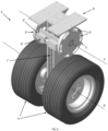
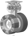
figures 8 and9 show a group ofwheels 3, respectively in perspective and exploded view. - According to a preferred embodiment of the present invention, the
rubber wheels 4 of each group ofwheels 3 are rotationally integral therebetween, mounted on the common wheel axis A. - The group of
wheels 3 is mounted on asmall frame 8 that is rendered integral to theframe 2 of thetowable structure - The means for locking the rotation of the
wheels 4 comprise a pair offlanges - The
flanges numbers 9 and 9' in the figures. - Furthermore, the locking means also comprise a pair of
pins 6, 6', integral with theframe 8, and adapted to interfere, when operated, each with theslots 9, 9' of one of theflanges - Furthermore, the locking means comprise a
transmission system 7, for example a crown and chain mechanism, that connects the flange axis F to the wheel axis A, thereby rendering them integral in rotation. - The mechanism for locking the rotation of the
wheels 4, the operation thereof will be described in greater detail below, has the already anticipated function of making it possible to lock the rotation of thewheels 4 of each group ofwheels 3 at a plurality of predetermined angular locking positions. - Advantageously, the locking means can be operated in such a way as to allow for the rotation of the
wheels 4 of each group from one locking position to another, during the operation of said towable structure, without interrupting the road surface treatment operations. - The following
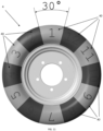
figures 10 and11 show a tyre of the group ofwheels 3, whereupon, purely by way of example and for the sole purposes of this description, indications are given in relation to possible sectors of a tyre and corresponding to as many predetermined positions. In the example, there are twelve positions, numbered from '1' to '12', each therefore corresponding to twelveangular sectors 40, each of 30°. - As illustrated in the subsequent
figures 12A and 12B , theslots 9, 9' are made at the peripheral circumference of eachflange - Preferably, the
slots 9, 9' all have the same length P along the circumference. - Furthermore, the
flanges wheels 3 are mounted out of phase with respect to one another such that the beginning of eachslot 9 on afirst flange 5 corresponds to the end of a slot 9' on asecond flange 5'. In this way each point of correspondence between theslots 9, 9' defines a corresponding predetermined position. According to the example described above,figures 12A and 12B show the twoflanges - The two
flanges -
Figure 12C shows the twoflanges slots 9, 9' and therefore the twelve predetermined positions. - The rotational blocking, as already clarified, occurs by means of two
pins 6, 6' which, when actuated, interfere respectively with one of theslots 9, 9' of theflanges - In order to illustrate in more detail what has just been described, the following
figure 13 shows some components in partial transparency. - The following figures from 14A to 14C illustrate the passage from one predetermined position to another predetermined position.
- The two
pins 6, 6' operate alternately.Figure 14A shows the pin 6' which interferes, considering the direction of rotation R of the parts indicated in the figure, with one end of a slot 9' of theflange 5'. This interference evidently blocks theflange 5' in rotation. Insofar as theflange 5' is integral in rotation with thewheels 4, thewheels 4 are also blocked due to such interference at the predetermined position corresponding to thesector 40 denoted by '12' on the tyre. - During this step, the
pin 6 is not operational and does not perform any function and therefore can - as in the figure - be retracted without interfering with thecorresponding slot 9 of theflange 5. - The following
figure 14B shows a transition step, between one position and another. - During this step, the two
pins 6 and 6' reverse the function and position thereof. The pin 6' retracts and relinquishes the interference and locking function, whilst thepin 6 extends and interferes with theslot 9 of theflange 5. - In this position, obviously, the
flanges wheels 4, can rotate according to the direction of rotation R indicated in the figure. - Such a rotation can persist for the entyre length of the
slot 9, until, as illustrated in the followingfigure 14C , thepin 6 comes to rest at one end of thesame slot 9, thereby locking the rotation of theflange 5. Consequently, thewheels 4 will have rotated by a corresponding angle (30°) in the direction of rotation R indicated in the figure and will then be blocked at adifferent sector 40, denoted in the figure by the number '11'.
Claims (11)
- Wheeled towable structure (1, 11), comprising:• a frame (2) on which a plurality of groups of wheels assemblies (3) are mounted, each group (3) comprising one or more rubber wheels (4), equipped with tyres and mounted so as to rotate at a respective wheel axis (A);• means (5, 5', 6, 6', 7) for locking the rotation of the wheels of each group of wheels (3) in predetermined locking positions;• means for actuating said means (5, 5', 6, 6', 7) for locking the rotation of the rubber wheels (4), configured to move the wheels of each group (3) from a locking position to another during the movement of said towable structure (1, 11),characterized in that said means (5, 5', 6, 6', 7) for locking the rotation comprises a pair of flanges (5, 5') coaxially mounted so as to rotate integrally around a flange axis (F) and respectively equipped with a plurality of slots (9, 9'), and a pair of pins (6, 6') integral with a frame (8) of said group of wheels (3) and adapted to interfere, when operated, each with the slots (9, 9') of one of said flanges (5, 5'), said means (5, 5', 6, 6', 7) further comprising a transmission system (7) which connects said flange axis (F) to said wheel axis (A).
- Towable structure (1, 11) according to claim 1, wherein each group of wheels (3) comprises two coaxial rubber wheels (4).
- Towable structure (1, 11) according to claim 1 or 2, wherein the rubber wheels (4) of each wheel group (3) are rotationally integral with each other.
- Towable structure (1, 11) according to one of the claims 1 to 3, wherein said slots (9, 9') are made at a peripheral circumference of each flange (5, 5'), equally distributed along said circumference.
- Towable structure (1, 11) according to one of the claims 1 to 4, in which said slots (9, 9') all have the same width along said circumference.
- Towable structure (1, 11) according to one of the claims 1 to 5, wherein said flanges (5, 5') of a pair of flanges are out of phase with respect to each other so that the beginning of each one slot (9) on a first flange (5) corresponds to the end of a slot (9') on a second flange (5'), each correspondence point between the slots (9, 9') defining a corresponding predetermined position.
- Towable structure (1, 11) according to one of claims 1 to 6, wherein said means for actuating comprises a mechanism for hydraulic actuation of said pins (6, 6').
- Towable structure (1, 11) according to one of claims 1 to 7, wherein said groups of wheels (3) are arranged on six axes (A) parallel to each other and orthogonal to a towing direction (T) of the structure (1, 11).
- Towable structure (1, 11) according to claim 8, in which said groups of wheels (3) are distributed on each of said six parallel axles (A), such that the footprint of the rubber wheels (4) of groups on different axes partially overlap, to fully cover the overall gauge (S) of the towable structure (1,11).
- Towable structure (11) according to one of claims 1 to 9, further comprising a pair of maneuvering wheels (14) mounted on an articulated mechanism (20), such that the maneuvering wheels (14) can be positioned in a first treatment position in which they are raised from the ground, the rubber wheels (4) being in contact with the ground, and a second maneuvering position in which they are in contact with the ground, the rubber wheels (4) being raised by the soil.
- Towable structure (1, 11) according to one of claims 1 to 10, further comprising a plurality of hydraulic jacks (30) for lifting it, so that the rubber wheels (4) are detached from the ground.
Applications Claiming Priority (2)
| Application Number | Priority Date | Filing Date | Title |
|---|---|---|---|
| IT202000031430 | 2020-12-18 | ||
| PCT/EP2021/085968 WO2022129212A1 (en) | 2020-12-18 | 2021-12-15 | Towable structure for the treatement of road surfaces |
Publications (2)
| Publication Number | Publication Date |
|---|---|
| EP4263945A1 EP4263945A1 (en) | 2023-10-25 |
| EP4263945B1 true EP4263945B1 (en) | 2025-01-29 |
Family
ID=74858626
Family Applications (1)
| Application Number | Title | Priority Date | Filing Date |
|---|---|---|---|
| EP21839912.9A Active EP4263945B1 (en) | 2020-12-18 | 2021-12-15 | Towable structure for the treatement of road surfaces |
Country Status (3)
| Country | Link |
|---|---|
| EP (1) | EP4263945B1 (en) |
| ES (1) | ES3017060T3 (en) |
| WO (1) | WO2022129212A1 (en) |
Family Cites Families (2)
| Publication number | Priority date | Publication date | Assignee | Title |
|---|---|---|---|---|
| DE4127791A1 (en) * | 1991-08-22 | 1993-02-25 | Rockinger Spezial Fab Joh | TRAILER WITH MOTOR DRIVEN SUPPORT |
| US10155529B2 (en) * | 2016-01-30 | 2018-12-18 | Intelli-Core Llc | Multi-function convertible trailer and towing structure |
-
2021
- 2021-12-15 ES ES21839912T patent/ES3017060T3/en active Active
- 2021-12-15 WO PCT/EP2021/085968 patent/WO2022129212A1/en not_active Ceased
- 2021-12-15 EP EP21839912.9A patent/EP4263945B1/en active Active
Also Published As
| Publication number | Publication date |
|---|---|
| ES3017060T3 (en) | 2025-05-12 |
| EP4263945A1 (en) | 2023-10-25 |
| WO2022129212A1 (en) | 2022-06-23 |
Similar Documents
| Publication | Publication Date | Title |
|---|---|---|
| EP2867095B1 (en) | Steering system for a vehicle and steering method for a vehicle | |
| US5375640A (en) | Pneumatic tire for offroad vehicles | |
| KR200453381Y1 (en) | Four-wheel drive truck using differential gear unit with direct drive and braking system | |
| DE4435160A1 (en) | Device for determining the peripheral force of a vehicle wheel | |
| EP3250439B1 (en) | Steering assembly for a riding lawn mower | |
| CN107878119B (en) | Tyre for vehicle wheels | |
| US4266483A (en) | Convertible rail-highway car moving vehicle | |
| US7243747B2 (en) | Trailer provided with manoeuvring device | |
| US4057158A (en) | Aircraft towing vehicle | |
| JPS61222806A (en) | Improvements in wheel driving car and radial-ply tire thereof | |
| EP4263945A1 (en) | Towable structure for the treatement of road surfaces | |
| JP5766469B2 (en) | tire | |
| EP1028086B1 (en) | Industrial truck with two steerable driving wheels | |
| EP2943359B1 (en) | Pneumatic vehicle tyre for use in winter driving conditions | |
| EP0093072B1 (en) | A pneumatic tire | |
| AU2013201119B2 (en) | Vehicle and drive mechanism | |
| JP6088483B2 (en) | tire | |
| DE102021110391A1 (en) | Method for performing a steering movement for a vehicle; System; computer program | |
| EP3159188A1 (en) | Racing tire with wear indicator | |
| DE439189C (en) | Drive device for motor vehicles with several drive wheels on each side of the car | |
| DE19836439A1 (en) | Pneumatic tires for multi-track vehicles | |
| JPS624611A (en) | Pneumatic tire for vehicle running on rough ground | |
| DE3931279A1 (en) | DEVICE FOR IMPROVING THE WINTER RUNNING CHARACTERISTICS OF VEHICLE TIRES | |
| FI103334B (en) | Figure knob ring | |
| KR20220096124A (en) | Step driveable omni-wheel device and their incorporating driving device |
Legal Events
| Date | Code | Title | Description |
|---|---|---|---|
| STAA | Information on the status of an ep patent application or granted ep patent |
Free format text: STATUS: UNKNOWN |
|
| STAA | Information on the status of an ep patent application or granted ep patent |
Free format text: STATUS: THE INTERNATIONAL PUBLICATION HAS BEEN MADE |
|
| PUAI | Public reference made under article 153(3) epc to a published international application that has entered the european phase |
Free format text: ORIGINAL CODE: 0009012 |
|
| STAA | Information on the status of an ep patent application or granted ep patent |
Free format text: STATUS: REQUEST FOR EXAMINATION WAS MADE |
|
| 17P | Request for examination filed |
Effective date: 20230714 |
|
| AK | Designated contracting states |
Kind code of ref document: A1 Designated state(s): AL AT BE BG CH CY CZ DE DK EE ES FI FR GB GR HR HU IE IS IT LI LT LU LV MC MK MT NL NO PL PT RO RS SE SI SK SM TR |
|
| DAV | Request for validation of the european patent (deleted) | ||
| DAX | Request for extension of the european patent (deleted) | ||
| GRAP | Despatch of communication of intention to grant a patent |
Free format text: ORIGINAL CODE: EPIDOSNIGR1 |
|
| STAA | Information on the status of an ep patent application or granted ep patent |
Free format text: STATUS: GRANT OF PATENT IS INTENDED |
|
| INTG | Intention to grant announced |
Effective date: 20240715 |
|
| GRAS | Grant fee paid |
Free format text: ORIGINAL CODE: EPIDOSNIGR3 |
|
| GRAA | (expected) grant |
Free format text: ORIGINAL CODE: 0009210 |
|
| STAA | Information on the status of an ep patent application or granted ep patent |
Free format text: STATUS: THE PATENT HAS BEEN GRANTED |
|
| AK | Designated contracting states |
Kind code of ref document: B1 Designated state(s): AL AT BE BG CH CY CZ DE DK EE ES FI FR GB GR HR HU IE IS IT LI LT LU LV MC MK MT NL NO PL PT RO RS SE SI SK SM TR |
|
| REG | Reference to a national code |
Ref country code: GB Ref legal event code: FG4D |
|
| REG | Reference to a national code |
Ref country code: CH Ref legal event code: EP |
|
| REG | Reference to a national code |
Ref country code: DE Ref legal event code: R096 Ref document number: 602021025613 Country of ref document: DE |
|
| REG | Reference to a national code |
Ref country code: IE Ref legal event code: FG4D |
|
| REG | Reference to a national code |
Ref country code: ES Ref legal event code: FG2A Ref document number: 3017060 Country of ref document: ES Kind code of ref document: T3 Effective date: 20250512 |
|
| REG | Reference to a national code |
Ref country code: NL Ref legal event code: MP Effective date: 20250129 |
|
| PG25 | Lapsed in a contracting state [announced via postgrant information from national office to epo] |
Ref country code: NL Free format text: LAPSE BECAUSE OF FAILURE TO SUBMIT A TRANSLATION OF THE DESCRIPTION OR TO PAY THE FEE WITHIN THE PRESCRIBED TIME-LIMIT Effective date: 20250129 |
|
| PG25 | Lapsed in a contracting state [announced via postgrant information from national office to epo] |
Ref country code: RS Free format text: LAPSE BECAUSE OF FAILURE TO SUBMIT A TRANSLATION OF THE DESCRIPTION OR TO PAY THE FEE WITHIN THE PRESCRIBED TIME-LIMIT Effective date: 20250429 |
|
| PG25 | Lapsed in a contracting state [announced via postgrant information from national office to epo] |
Ref country code: FI Free format text: LAPSE BECAUSE OF FAILURE TO SUBMIT A TRANSLATION OF THE DESCRIPTION OR TO PAY THE FEE WITHIN THE PRESCRIBED TIME-LIMIT Effective date: 20250129 |
|
| PG25 | Lapsed in a contracting state [announced via postgrant information from national office to epo] |
Ref country code: PL Free format text: LAPSE BECAUSE OF FAILURE TO SUBMIT A TRANSLATION OF THE DESCRIPTION OR TO PAY THE FEE WITHIN THE PRESCRIBED TIME-LIMIT Effective date: 20250129 |
|
| REG | Reference to a national code |
Ref country code: LT Ref legal event code: MG9D |
|
| PG25 | Lapsed in a contracting state [announced via postgrant information from national office to epo] |
Ref country code: IS Free format text: LAPSE BECAUSE OF FAILURE TO SUBMIT A TRANSLATION OF THE DESCRIPTION OR TO PAY THE FEE WITHIN THE PRESCRIBED TIME-LIMIT Effective date: 20250529 Ref country code: NO Free format text: LAPSE BECAUSE OF FAILURE TO SUBMIT A TRANSLATION OF THE DESCRIPTION OR TO PAY THE FEE WITHIN THE PRESCRIBED TIME-LIMIT Effective date: 20250429 |
|
| REG | Reference to a national code |
Ref country code: AT Ref legal event code: MK05 Ref document number: 1763547 Country of ref document: AT Kind code of ref document: T Effective date: 20250129 |
|
| PG25 | Lapsed in a contracting state [announced via postgrant information from national office to epo] |
Ref country code: HR Free format text: LAPSE BECAUSE OF FAILURE TO SUBMIT A TRANSLATION OF THE DESCRIPTION OR TO PAY THE FEE WITHIN THE PRESCRIBED TIME-LIMIT Effective date: 20250129 |
|
| PG25 | Lapsed in a contracting state [announced via postgrant information from national office to epo] |
Ref country code: PT Free format text: LAPSE BECAUSE OF FAILURE TO SUBMIT A TRANSLATION OF THE DESCRIPTION OR TO PAY THE FEE WITHIN THE PRESCRIBED TIME-LIMIT Effective date: 20250529 Ref country code: LV Free format text: LAPSE BECAUSE OF FAILURE TO SUBMIT A TRANSLATION OF THE DESCRIPTION OR TO PAY THE FEE WITHIN THE PRESCRIBED TIME-LIMIT Effective date: 20250129 |
|
| PG25 | Lapsed in a contracting state [announced via postgrant information from national office to epo] |
Ref country code: BG Free format text: LAPSE BECAUSE OF FAILURE TO SUBMIT A TRANSLATION OF THE DESCRIPTION OR TO PAY THE FEE WITHIN THE PRESCRIBED TIME-LIMIT Effective date: 20250129 Ref country code: GR Free format text: LAPSE BECAUSE OF FAILURE TO SUBMIT A TRANSLATION OF THE DESCRIPTION OR TO PAY THE FEE WITHIN THE PRESCRIBED TIME-LIMIT Effective date: 20250430 |
|
| PG25 | Lapsed in a contracting state [announced via postgrant information from national office to epo] |
Ref country code: AT Free format text: LAPSE BECAUSE OF FAILURE TO SUBMIT A TRANSLATION OF THE DESCRIPTION OR TO PAY THE FEE WITHIN THE PRESCRIBED TIME-LIMIT Effective date: 20250129 |
|
| PG25 | Lapsed in a contracting state [announced via postgrant information from national office to epo] |
Ref country code: SE Free format text: LAPSE BECAUSE OF FAILURE TO SUBMIT A TRANSLATION OF THE DESCRIPTION OR TO PAY THE FEE WITHIN THE PRESCRIBED TIME-LIMIT Effective date: 20250129 |
|
| PG25 | Lapsed in a contracting state [announced via postgrant information from national office to epo] |
Ref country code: SM Free format text: LAPSE BECAUSE OF FAILURE TO SUBMIT A TRANSLATION OF THE DESCRIPTION OR TO PAY THE FEE WITHIN THE PRESCRIBED TIME-LIMIT Effective date: 20250129 |
|
| PG25 | Lapsed in a contracting state [announced via postgrant information from national office to epo] |
Ref country code: DK Free format text: LAPSE BECAUSE OF FAILURE TO SUBMIT A TRANSLATION OF THE DESCRIPTION OR TO PAY THE FEE WITHIN THE PRESCRIBED TIME-LIMIT Effective date: 20250129 |
|
| PG25 | Lapsed in a contracting state [announced via postgrant information from national office to epo] |
Ref country code: IT Free format text: LAPSE BECAUSE OF FAILURE TO SUBMIT A TRANSLATION OF THE DESCRIPTION OR TO PAY THE FEE WITHIN THE PRESCRIBED TIME-LIMIT Effective date: 20250129 |
|
| PG25 | Lapsed in a contracting state [announced via postgrant information from national office to epo] |
Ref country code: EE Free format text: LAPSE BECAUSE OF FAILURE TO SUBMIT A TRANSLATION OF THE DESCRIPTION OR TO PAY THE FEE WITHIN THE PRESCRIBED TIME-LIMIT Effective date: 20250129 Ref country code: CZ Free format text: LAPSE BECAUSE OF FAILURE TO SUBMIT A TRANSLATION OF THE DESCRIPTION OR TO PAY THE FEE WITHIN THE PRESCRIBED TIME-LIMIT Effective date: 20250129 |
|
| PG25 | Lapsed in a contracting state [announced via postgrant information from national office to epo] |
Ref country code: RO Free format text: LAPSE BECAUSE OF FAILURE TO SUBMIT A TRANSLATION OF THE DESCRIPTION OR TO PAY THE FEE WITHIN THE PRESCRIBED TIME-LIMIT Effective date: 20250129 |
|
| PG25 | Lapsed in a contracting state [announced via postgrant information from national office to epo] |
Ref country code: SK Free format text: LAPSE BECAUSE OF FAILURE TO SUBMIT A TRANSLATION OF THE DESCRIPTION OR TO PAY THE FEE WITHIN THE PRESCRIBED TIME-LIMIT Effective date: 20250129 |
|
| REG | Reference to a national code |
Ref country code: DE Ref legal event code: R097 Ref document number: 602021025613 Country of ref document: DE |
|
| PLBE | No opposition filed within time limit |
Free format text: ORIGINAL CODE: 0009261 |
|
| STAA | Information on the status of an ep patent application or granted ep patent |
Free format text: STATUS: NO OPPOSITION FILED WITHIN TIME LIMIT |
|
| 26N | No opposition filed |
Effective date: 20251030 |
|
| PGFP | Annual fee paid to national office [announced via postgrant information from national office to epo] |
Ref country code: DE Payment date: 20251126 Year of fee payment: 5 |
|
| PGFP | Annual fee paid to national office [announced via postgrant information from national office to epo] |
Ref country code: FR Payment date: 20251120 Year of fee payment: 5 |
|
| PGFP | Annual fee paid to national office [announced via postgrant information from national office to epo] |
Ref country code: ES Payment date: 20260102 Year of fee payment: 5 |