EP4263243B1 - Rotating joint - Google Patents
Rotating joint Download PDFInfo
- Publication number
- EP4263243B1 EP4263243B1 EP20851301.0A EP20851301A EP4263243B1 EP 4263243 B1 EP4263243 B1 EP 4263243B1 EP 20851301 A EP20851301 A EP 20851301A EP 4263243 B1 EP4263243 B1 EP 4263243B1
- Authority
- EP
- European Patent Office
- Prior art keywords
- shoulder
- valve
- channel
- rotating joint
- disc
- Prior art date
- Legal status (The legal status is an assumption and is not a legal conclusion. Google has not performed a legal analysis and makes no representation as to the accuracy of the status listed.)
- Active
Links
Images


Classifications
-
- B—PERFORMING OPERATIONS; TRANSPORTING
- B60—VEHICLES IN GENERAL
- B60C—VEHICLE TYRES; TYRE INFLATION; TYRE CHANGING; CONNECTING VALVES TO INFLATABLE ELASTIC BODIES IN GENERAL; DEVICES OR ARRANGEMENTS RELATED TO TYRES
- B60C23/00—Devices for measuring, signalling, controlling, or distributing tyre pressure or temperature, specially adapted for mounting on vehicles; Arrangement of tyre inflating devices on vehicles, e.g. of pumps or of tanks; Tyre cooling arrangements
- B60C23/001—Devices for manually or automatically controlling or distributing tyre pressure whilst the vehicle is moving
- B60C23/003—Devices for manually or automatically controlling or distributing tyre pressure whilst the vehicle is moving comprising rotational joints between vehicle-mounted pressure sources and the tyres
- B60C23/00345—Details of the rotational joints
- B60C23/00347—Details of the rotational joints comprising two or more feedthrough
-
- B—PERFORMING OPERATIONS; TRANSPORTING
- B29—WORKING OF PLASTICS; WORKING OF SUBSTANCES IN A PLASTIC STATE IN GENERAL
- B29C—SHAPING OR JOINING OF PLASTICS; SHAPING OF MATERIAL IN A PLASTIC STATE, NOT OTHERWISE PROVIDED FOR; AFTER-TREATMENT OF THE SHAPED PRODUCTS, e.g. REPAIRING
- B29C73/00—Repairing of articles made from plastics or substances in a plastic state, e.g. of articles shaped or produced by using techniques covered by this subclass or subclass B29D
- B29C73/16—Auto-repairing or self-sealing arrangements or agents
- B29C73/166—Devices or methods for introducing sealing compositions into articles
-
- B—PERFORMING OPERATIONS; TRANSPORTING
- B60—VEHICLES IN GENERAL
- B60C—VEHICLE TYRES; TYRE INFLATION; TYRE CHANGING; CONNECTING VALVES TO INFLATABLE ELASTIC BODIES IN GENERAL; DEVICES OR ARRANGEMENTS RELATED TO TYRES
- B60C23/00—Devices for measuring, signalling, controlling, or distributing tyre pressure or temperature, specially adapted for mounting on vehicles; Arrangement of tyre inflating devices on vehicles, e.g. of pumps or of tanks; Tyre cooling arrangements
- B60C23/001—Devices for manually or automatically controlling or distributing tyre pressure whilst the vehicle is moving
- B60C23/003—Devices for manually or automatically controlling or distributing tyre pressure whilst the vehicle is moving comprising rotational joints between vehicle-mounted pressure sources and the tyres
- B60C23/00309—Devices for manually or automatically controlling or distributing tyre pressure whilst the vehicle is moving comprising rotational joints between vehicle-mounted pressure sources and the tyres characterised by the location of the components, e.g. valves, sealings, conduits or sensors
- B60C23/00336—Devices for manually or automatically controlling or distributing tyre pressure whilst the vehicle is moving comprising rotational joints between vehicle-mounted pressure sources and the tyres characterised by the location of the components, e.g. valves, sealings, conduits or sensors on the axles
-
- B—PERFORMING OPERATIONS; TRANSPORTING
- B29—WORKING OF PLASTICS; WORKING OF SUBSTANCES IN A PLASTIC STATE IN GENERAL
- B29L—INDEXING SCHEME ASSOCIATED WITH SUBCLASS B29C, RELATING TO PARTICULAR ARTICLES
- B29L2030/00—Pneumatic or solid tyres or parts thereof
-
- B—PERFORMING OPERATIONS; TRANSPORTING
- B60—VEHICLES IN GENERAL
- B60C—VEHICLE TYRES; TYRE INFLATION; TYRE CHANGING; CONNECTING VALVES TO INFLATABLE ELASTIC BODIES IN GENERAL; DEVICES OR ARRANGEMENTS RELATED TO TYRES
- B60C23/00—Devices for measuring, signalling, controlling, or distributing tyre pressure or temperature, specially adapted for mounting on vehicles; Arrangement of tyre inflating devices on vehicles, e.g. of pumps or of tanks; Tyre cooling arrangements
- B60C23/001—Devices for manually or automatically controlling or distributing tyre pressure whilst the vehicle is moving
- B60C23/002—Devices for manually or automatically controlling or distributing tyre pressure whilst the vehicle is moving by monitoring conditions other than tyre pressure or deformation
Definitions
- the present invention refers to a rotating joint.
- the present invention relates to devices for manual or automatic control of the tire inflation pressure while the vehicle is in motion, that is to say, a rotating joint between the vehicle and the tire.
- the present invention relates to gaskets with a gasket ring expanded or pressed into position by pressure, for example, inflatable gaskets influenced by the pressure inside the element to be sealed.
- IT-A-201700092610 relates to a device for inflating and/or repairing a tire while a vehicle is running, the tire having a rim, a hub and a pivot pin on bearings, the device providing means for supplying pressurized air, a pressurized air inlet in the pin/hub/rim assembly, a chamber in the pin/hub/rim assembly.
- the device comprises a valve 10 sliding on the pin 4, along a direction parallel to an axis of longitudinal extension of the pin 4 itself, following the introduction of the pressurized air into the chamber 8 to abut against the shoulders 12 to prevent the passage of pressurized air towards the bearings 11, and move away from them following the removal of the supply of pressurized air, a channel 13 for the passage of air from the chamber 8 towards the tire 1, and means for detecting the pressure of the tire 1 for activating alarm means, and means for actuating the device following the activation of the alarm means. Furthermore, on the channel 13 for the passage of the pressurized air towards the tire 1, there is a two-way electric valve 14 for diverting air to a tank 16 of repair material, the air exiting the tank 16 mixed with repair product and going to the tire 1.
- US-B2-9,649,893 relates to a rotating passage for a compressed air supply system provided between a stator and a rotor rotating with respect to this stator.
- a compressed air channel arranged in the stator is connected to a compressed air line and leads into an annular chamber formed in the rotor, from which at least one working channel leads to a user.
- the stator is connected in the region of the rotating bushing to a control line.
- a frictional moment occurring in the region of the rotating bushing resulting in premature wear is reduced by providing a switchable non-return valve in the annular chamber.
- Locking elements extending inside the annular chamber concentrically to the axis of rotation of the rotor are movable in an open position by a driving element, which is displaced by the stator in the direction of the locking elements.
- DE-B3-1 02015 013 693 relates to a retrofittable annular rotating passage consisting of an inner ring 2 and an outer ring 3.
- the task is solved by an O-ring gasket with the function of making a compressed air seal and two dirt sealing gaskets.
- JP-A-2009-056948 relates to an air pressure supply device including an air pressure source provided in a non-rotating body of the vehicle, capable of supplying air pressure to at least one tire of a plurality of vehicle wheels, the air pressure supply device comprises a rotating seal to ensure the fluid connection between the rotating body which rotates together with the tire and the non-rotating body.
- the device of IT201700092610 may present the problem of wear of the valve 10 sliding on the pin 4, during the introduction of pressurized air into the chamber 8, the valve 10 abutting against the shoulders 12 tending to rotate on the pin 4 subjected to a frictional moment which causes wear due to sanding inside the device.
- the purpose of the present invention is solving the aforementioned prior art problems by providing a rotating joint free of relative motions of the parts that compose it to avoid the establishment of friction pairs and trigger problems of wear of the material.
- Another object is providing a joint which ensures perfect pneumatic sealing of the internal chamber to the rotating joint and at the same time which remains protected from any external atmospheric agent such as dust, water, etc.
- a further purpose is diversifying the use of a rotating joint in a split circuit to be able to inflate the tire and, in a further phase, to be able to repair the tire.
- a further object is electronically controlling the circuit in which the rotating joint is located in order to be able to transmit data to an external console.
- a rotating joint to allow pressurized air to be fed, through a hub 1, from a rotation pin 2 with respect to an axis XX on bearings 3 to a tire 4 on a rim 5, comprises a distribution spool 6 to prevent the passage of pressurized air through the bearings 3.
- the distribution spool 6 comprises at least one valve 7, 8, against a respective disc with a first shoulder 9, and a disc with a second shoulder 10.
- At least one guiding device consisting of at least one protruding tooth 11, 12 able to slide with respect to a grooved support 13, 14, prevents rotation of the valve 7, 8 with respect to the rotation pin 2.
- the valve 7, 8 slides freely along a direction parallel to the X-X axis.
- This at least one protruding tooth 11, 12 is integral with the valve 7, 8, while the grooved support 13, 14 is integral with a ring 15, 16.
- the ring 15, 16 is keyed or one piece with respect to the rotation pin 2.
- the respective disk with a first shoulder 9, disk with a second shoulder 10, coaxial to the valve 7, 8 comprises at least one sealing ring 17 keyed onto a shaped seat of an outer circular edge of the respective first shoulder 9, second shoulder 10.
- Such at least one sealing ring 17 presses radially on the internal surface of the hub 1.
- valve 7, 8 comprises at least one sealing ring 26 keyed onto a shaped seat of an internal circular edge of the valve 7, 8.
- the hub 1 comprises a breather channel 27 positioned at the height of this at least one sealing ring 17.
- the breather channel 27 is adapted to connect the internal surface of the hub 1 with a pneumatic non-return valve 28 positioned on the external surface of the hub 1, to allow the sliding of the valve 7, 8.
- the pressurized air is fed through a first channel 18, with the valve 7 against the disc with a first shoulder 9, to allow pressurized air to be fed through a tank 20 of repair material carried by the pressurized air.
- pressurized air is fed through a second channel 19, with the valve 8 against the disc with a second shoulder 10, to allow pressurized air to be fed through a tank 20 of repair material transported by pressurized air.
- An electronic control unit 21 allows to selectively feed air under pressure through the first channel 18 and the second channel 19.
- the tank 20 is arranged on the hub 1.
- the tank 20 is detached from the hub 1 and made inside the rim 5.
- the tank 20 is refillable. Alternatively, the tank 20 can be replaced by means of a cartridge.
- such at least one valve 7, 8 is detached from the respective disc with a first shoulder 9, and the disc with a second shoulder 10, by means of supplying pressurized air 24, 25, connected with the respective first channel 18 and second channel 19.
- the respective disk with a first shoulder 9, and the disk with a second shoulder 10 comprises a rotating seal to ensure the sealing of the air under pressure between the respective disk with a first shoulder 9, a disk with a second shoulder 10 and the rotation pin 2.
- the rotating seal adhering to a temperature sensor connected to the electronic control unit 21 allows to selectively supply pressurized air through the first channel 18 and the second channel 19, continuously or intermittently, depending on the temperature detected and the instantaneous rotation speed measured.
- valve 7, 8 slides freely along a direction parallel to the XX axis, guaranteeing pressure tightness as inside it, on the XX axis side, sealing rings 26 are inserted in order to guarantee a perfect tightness to the pressurized air and totally preserve the valve 7, 8, from wear due to sanding.
- the O-ring is designed as a floating O-ring.
- the O-ring is not rubber, but a rigid and lubricating plastic is produced.
- the O-ring is brought to its inner diameter with a conical surface, which is preferably a part of the inner ring wall in contact.
- the groove of the O-ring is significantly greater than the thickness of the O-ring in both width and height.
- the O-ring preferably has a diameter of about 3 mm.
- the O-ring can move in a buoyant relationship with the O-ring groove positioned both axially and radially and is applied when pressure is applied to the outward facing seal from the pressure side wall of the O-ring groove, which is preferably a part of the outer ring.
- the process is not temporarily free of losses, which does not affect the function of the rotating union.
- the inner ring having the tapered surface towards the side wall of the O-ring groove has an angle of inclination with respect to the axis of rotation of the rotating union of at least 10°.
- the object of the present invention is an evolution of the device described in document IT201700092610 .
- the rotating joint comes into operation by moving the valves towards the ends and in contact with the shoulders.
- the contact between the two elements causes the valves to rotate on the pivot pin, causing wear over time due to smoothing inside the valves.
- Two channels 18, 19 are formed in the rotation pin of the wheel, with separate and independent inputs, in order to perform two distinct roles: tire inflation only; tire inflation and repair.
- pressurized air is sent through the two channels 18, 19, selectively.
- the pressurized air is contained in a tank which is kept charged by a portable mini compressor even if low pressures such as those available at the outlet of the portable mini compressors on the market are required, both the tank and any mini compressor installed on board the vehicle.
- the transmission of information and/or signals on the condition of the tire are brought to a control unit with wireless transmission systems through sensors installed on the valves of the tire itself, the data on the condition of the tire are visible to the driver by means of a screen mounted on the vehicle.
- the activation and deactivation of the inflation and repair functions takes place by means of an electronic system entirely mounted on the vehicle which does not require any electrical contact with the device, rotating joint, thus eliminating all the sliding electrical contacts and the relative rotating means.
- the system can be activated automatically by the electronic control unit or in second case manually by the driver.
- the first channel 18 passes through the rotation pin, up to approximately one third of the length of the rotation pin, the pressurized air introduced into the first channel 18 enters the portion of the distribution box delimited by the first two shoulders 9.
- the pressurized air it pushes the valve 7 against the two first shoulders 9 with consequent output of the low pressure air from the channels 27 and from the pneumatic non-return valves 28. In this way, the movement of the valve 7 takes place without any kind of disturbance.
- the pressurized air enters the tire through a channel 31 equipped with a safety valve.
- Identical valve structure is provided for the second channel, always made inside the rotation pin, on the same side of the first channel, or alternatively, on the opposite side with respect to the first channel through the rotation pin up to about two thirds of the length of the rotation pin.
- the pressurized air introduced into the second channel 19 enters the portion of the distribution box delimited by the two second shoulders 10, the valve 8 striking against the two second shoulders allows the introduction of pressurized air into the tank containing the repair liquid through a channel 29 equipped with safety valve.
- a second channel 30 equipped with a safety valve that allows the injection of repair liquid and pressurized air inside the tire to allow the repair and inflation of the tire.
- pressurized air enters the tank causing the sealing product to escape from an additional channel downstream of the tank, bringing the pressurized air/repair product mixture to an additional valve on the tire.
- the tank was built in a first draft of the project around the hub but it is also possible to build it inside the rim.
Landscapes
- Engineering & Computer Science (AREA)
- Mechanical Engineering (AREA)
Description
- The present invention refers to a rotating joint.
- In general, the present invention relates to devices for manual or automatic control of the tire inflation pressure while the vehicle is in motion, that is to say, a rotating joint between the vehicle and the tire.
- In particular, the present invention relates to gaskets with a gasket ring expanded or pressed into position by pressure, for example, inflatable gaskets influenced by the pressure inside the element to be sealed.
-
IT-A-201700092610 valve 10 sliding on thepin 4, along a direction parallel to an axis of longitudinal extension of thepin 4 itself, following the introduction of the pressurized air into thechamber 8 to abut against theshoulders 12 to prevent the passage of pressurized air towards thebearings 11, and move away from them following the removal of the supply of pressurized air, achannel 13 for the passage of air from thechamber 8 towards thetire 1, and means for detecting the pressure of thetire 1 for activating alarm means, and means for actuating the device following the activation of the alarm means. Furthermore, on thechannel 13 for the passage of the pressurized air towards thetire 1, there is a two-wayelectric valve 14 for diverting air to atank 16 of repair material, the air exiting thetank 16 mixed with repair product and going to thetire 1. -
US-B2-9,649,893 -
DE-B3-1 02015 013 693 relates to a retrofittable annular rotating passage consisting of aninner ring 2 and anouter ring 3. A pair of floatingsealing rings inner ring 2 and theouter ring 3 up to at least +/- 0.5 mm, without damage creates a precise guide between theinner ring 2 and theouter ring 3. The task is solved by an O-ring gasket with the function of making a compressed air seal and two dirt sealing gaskets. -
JP-A-2009-056948 - A relevant state of the art is represented by the following patent documents:
WO-A2-2014/063873 ;US-A-4,804,027 ;EP-A1-3 484 731 . - The device of
IT201700092610 valve 10 sliding on thepin 4, during the introduction of pressurized air into thechamber 8, thevalve 10 abutting against theshoulders 12 tending to rotate on thepin 4 subjected to a frictional moment which causes wear due to sanding inside the device. - The purpose of the present invention is solving the aforementioned prior art problems by providing a rotating joint free of relative motions of the parts that compose it to avoid the establishment of friction pairs and trigger problems of wear of the material.
- Another object is providing a joint which ensures perfect pneumatic sealing of the internal chamber to the rotating joint and at the same time which remains protected from any external atmospheric agent such as dust, water, etc.
- A further purpose is diversifying the use of a rotating joint in a split circuit to be able to inflate the tire and, in a further phase, to be able to repair the tire.
- A further object is electronically controlling the circuit in which the rotating joint is located in order to be able to transmit data to an external console.
- The aforementioned and other purposes and advantages of the invention, which will appear from the following description, are achieved with a rotating joint such as that described in
claim 1. Preferred embodiments and non-trivial variants of the present invention form the subject of the dependent claims. It is understood that all the attached claims form an integral part of the present description. - It will be immediately obvious that innumerable variations and modifications (for example relating to shape, dimensions, arrangements and parts with equivalent functionality) can be made to what has been described without departing from the scope of the invention as appears from the attached claims.
- The present invention will be better described by some preferred embodiments, provided by way of non-limiting example, with reference to the attached drawings.
-
Figure 1 shows a sectional view on a plane passing through a main rotation axis in a first configuration of an embodiment of the rotating joint according to the present invention. -
Figure 2 shows the same view of the previous figure in section on a plane passing through a main rotation axis in a second configuration of an embodiment of the rotating joint according to the present invention. -
Figure 3 shows a sectional view on a plane passing through a main rotation axis in a first variation of an embodiment of the rotating joint according to the present invention. -
Figure 4 shows a sectional view on a plane passing through a main rotation axis in a second variation of an embodiment of the rotating joint according to the present invention. -
Figure 5 shows a perspective view of a subassembly of an embodiment of the rotating joint according to the present invention. - With reference to
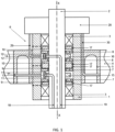
Figures 1 and2 , it is possible to note that a rotating joint, to allow pressurized air to be fed, through ahub 1, from arotation pin 2 with respect to an axis XX onbearings 3 to atire 4 on arim 5, comprises adistribution spool 6 to prevent the passage of pressurized air through thebearings 3. Thedistribution spool 6 comprises at least onevalve first shoulder 9, and a disc with asecond shoulder 10. - Advantageously, at least one guiding device consisting of at least one protruding
tooth grooved support valve rotation pin 2. - The
valve - This at least one protruding
tooth valve grooved support ring - The
ring rotation pin 2. - The respective disk with a
first shoulder 9, disk with asecond shoulder 10, coaxial to thevalve sealing ring 17 keyed onto a shaped seat of an outer circular edge of the respectivefirst shoulder 9,second shoulder 10. - Such at least one sealing
ring 17 presses radially on the internal surface of thehub 1. - With reference to
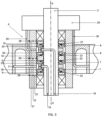
Figures 3 and4 , thevalve sealing ring 26 keyed onto a shaped seat of an internal circular edge of thevalve - The sealing
ring 26 presses radially on the surface of therotation pin 2. - The
hub 1 comprises abreather channel 27 positioned at the height of this at least onesealing ring 17. Thebreather channel 27 is adapted to connect the internal surface of thehub 1 with a pneumaticnon-return valve 28 positioned on the external surface of thehub 1, to allow the sliding of thevalve - With reference to
Figure 5 , the pressurized air is fed through afirst channel 18, with thevalve 7 against the disc with afirst shoulder 9, to allow pressurized air to be fed through atank 20 of repair material carried by the pressurized air. - Alternatively, the pressurized air is fed through a
second channel 19, with thevalve 8 against the disc with asecond shoulder 10, to allow pressurized air to be fed through atank 20 of repair material transported by pressurized air. - An
electronic control unit 21 allows to selectively feed air under pressure through thefirst channel 18 and thesecond channel 19. - Preferably, the
tank 20 is arranged on thehub 1. Alternatively, thetank 20 is detached from thehub 1 and made inside therim 5. - The
tank 20 is refillable. Alternatively, thetank 20 can be replaced by means of a cartridge. - In a first variation, with reference to
Figure 3 , this at least onevalve first shoulder 9, and a disc with asecond shoulder 10, by means of elastic return means 22, 23. - In a second variation, referring to
Figure 4 , such at least onevalve first shoulder 9, and the disc with asecond shoulder 10, by means of supplyingpressurized air first channel 18 andsecond channel 19. - In a further variant, not shown, the respective disk with a
first shoulder 9, and the disk with asecond shoulder 10, comprises a rotating seal to ensure the sealing of the air under pressure between the respective disk with afirst shoulder 9, a disk with asecond shoulder 10 and therotation pin 2. The rotating seal adhering to a temperature sensor connected to theelectronic control unit 21 allows to selectively supply pressurized air through thefirst channel 18 and thesecond channel 19, continuously or intermittently, depending on the temperature detected and the instantaneous rotation speed measured. - The
valve sealing rings 26 are inserted in order to guarantee a perfect tightness to the pressurized air and totally preserve thevalve - The passage of the rotating cable only for about 10% of the operating time, in any case corresponds to only a few minutes under pressure, the remaining 90% of the operating time is used to make a seal without pneumatic load and with friction reduced to a minimum. Since the rotating union has to work without maintenance it is necessary to do without lubrication.
- Therefore, the seal is almost frictionless against compressed air in the unpressurized state, the O-ring is designed as a floating O-ring. To achieve low coefficients of friction under pressure, the O-ring is not rubber, but a rigid and lubricating plastic is produced. In contrast to floating O-rings, as known in linear moving pneumatic cylinders, the O-ring is brought to its inner diameter with a conical surface, which is preferably a part of the inner ring wall in contact. The groove of the O-ring is significantly greater than the thickness of the O-ring in both width and height. The O-ring preferably has a diameter of about 3 mm. The O-ring can move in a buoyant relationship with the O-ring groove positioned both axially and radially and is applied when pressure is applied to the outward facing seal from the pressure side wall of the O-ring groove, which is preferably a part of the outer ring. The process is not temporarily free of losses, which does not affect the function of the rotating union. Preferably, the inner ring having the tapered surface towards the side wall of the O-ring groove has an angle of inclination with respect to the axis of rotation of the rotating union of at least 10°.
- The object of the present invention is an evolution of the device described in document
IT201700092610 - The rotating joint comes into operation by moving the valves towards the ends and in contact with the shoulders. The contact between the two elements causes the valves to rotate on the pivot pin, causing wear over time due to smoothing inside the valves.
- To overcome this problem, the guiding device was introduced.
- The guiding device is constituted by a
grooved seat valve tooth ring - Two
channels - In the rotating joint, pressurized air is sent through the two
channels - The transmission of information and/or signals on the condition of the tire are brought to a control unit with wireless transmission systems through sensors installed on the valves of the tire itself, the data on the condition of the tire are visible to the driver by means of a screen mounted on the vehicle. The activation and deactivation of the inflation and repair functions takes place by means of an electronic system entirely mounted on the vehicle which does not require any electrical contact with the device, rotating joint, thus eliminating all the sliding electrical contacts and the relative rotating means. The system can be activated automatically by the electronic control unit or in second case manually by the driver.
- Two procedures are possible.
- Inflation of the tire. The
first channel 18 passes through the rotation pin, up to approximately one third of the length of the rotation pin, the pressurized air introduced into thefirst channel 18 enters the portion of the distribution box delimited by the first twoshoulders 9. The pressurized air it pushes thevalve 7 against the twofirst shoulders 9 with consequent output of the low pressure air from thechannels 27 and from the pneumaticnon-return valves 28. In this way, the movement of thevalve 7 takes place without any kind of disturbance. The pressurized air enters the tire through achannel 31 equipped with a safety valve. - Tire inflation and repair. Identical valve structure is provided for the second channel, always made inside the rotation pin, on the same side of the first channel, or alternatively, on the opposite side with respect to the first channel through the rotation pin up to about two thirds of the length of the rotation pin.
- The pressurized air introduced into the
second channel 19 enters the portion of the distribution box delimited by the twosecond shoulders 10, thevalve 8 striking against the two second shoulders allows the introduction of pressurized air into the tank containing the repair liquid through achannel 29 equipped with safety valve. From the tank starts asecond channel 30 equipped with a safety valve that allows the injection of repair liquid and pressurized air inside the tire to allow the repair and inflation of the tire. The two second shoulders, on which thevalves 8 and thevent channels 27 with the pneumaticnon-return valves 28 rest, act in such a way as to avoid that, once the rotating joint is activated, the pressurized air introduced through the second channel can damage the bearings. - The refillable tank with sealant product is fixed around the hub or, in the second case, built inside the rim.
- When the inflation and repair procedure is activated, pressurized air enters the tank causing the sealing product to escape from an additional channel downstream of the tank, bringing the pressurized air/repair product mixture to an additional valve on the tire.
- The tank was built in a first draft of the project around the hub but it is also possible to build it inside the rim.
Claims (10)
- Rotating joint, to allow pressurized air to be fed, through a hub (1), from a rotation pin (2) with respect to an axis (XX) on bearings (3) to a tire (4) on a rim (5), comprising a distribution box (6) to prevent the passage of pressurized air through the bearings (3), said distribution box (6) comprising at least one valve (7, 8), against a respective disc with a first shoulder (9), or a disc with a second shoulder (10), characterized in that said rotating joint comprises at least one guiding device consisting of at least one protruding tooth (11, 12) able to slide relative to a grooved support (13, 14) to prevent rotation of the valve (7, 8) with respect to the rotation pin (2), the valve (7, 8) sliding freely along a direction parallel to said axis (XX).
- Rotating joint according to the previous claim, characterized in that said at least one protruding tooth (11, 12) is integral with the valve (7, 8), while said grooved support (13, 14) is integral with a ring (15, 16), said ring (15, 16) keyed or in one piece with respect to the rotation pin (2).
- Rotating joint according to claim l, characterized in that said respective disc with a first shoulder (9), or disc with a second shoulder (10), coaxial to the valve (7, 8) comprises at least one sealing ring (17) keyed on a shaped seat of an outer circular edge of said respective disc with a first shoulder (9), or a disc with a second shoulder (10), said at least one sealing ring (17) pressing radially on the internal surface of the hub (1).
- Rotating joint according to one of the preceding claims, characterized in that the valve (7, 8) comprises at least one sealing ring (26) keyed onto a shaped seat of an inner circular edge of the valve (7, 8), said at least one sealing ring (26) pressing radially on the surface of the rotation pin (2).
- Rotating joint according to claim 3, characterized in that the hub (1) comprises a vent channel (27) positioned at the height of said at least one sealing ring (17), said vent channel (27) adapted to connect the internal surface of the hub (1) with a pneumatic non-return valve (28) positioned on the external surface of the hub (1).
- Rotating joint according to one of the preceding claims, characterized in that it comprises an electronic control unit (21), to allow selectively supplying pressurized air through a first channel (18) and a second channel (19), through a tank (20) of repair material carried by the pressurized air, said first channel (18) with the valve (7) against the disc with a first shoulder (9), and said second channel (19) with the valve (8) against the discwith a second shoulder (10).
- Rotating joint according to claim 6, characterized in that the tank (20) is arranged on the hub (1) or detached from the hub (1) being made inside the rim (5), and in that the tank (20) is refillable or replaceable by a cartridge.
- Rotating joint according to one of the preceding claims, characterized in that said at least one valve (7, 8) is detached from said respective disc with a first shoulder (9), or a disc with a second shoulder (10), by means of a spring-back (22, 23).
- Rotating joint according to claim 6, characterized in that said at least one valve (7, 8) is detached from said respective disc with a first shoulder (9), or the disc with a second shoulder (10), by means for supplying pressurized air (24, 25), said means for supplying pressurized air (24, 25) connected to the respective said first channel (18) and said second channel (19).
- Rotating joint according to claim 3, characterized in that said respective disk with a first shoulder (9), or disk with a second shoulder (10), comprises a rotating seal to ensure the sealing of the air under pressure between said respective disk with a first shoulder (9), or the disk with a second shoulder (10) and the rotation pin (2), said rotating seal adhering to a temperature sensor connected to the electronic control unit (21) to allow selectively supplying pressurized air through the first channel (18) and the second channel (19), continuously or intermittently, depending on the detected temperature and the measured instantaneous rotation speed.
Applications Claiming Priority (1)
| Application Number | Priority Date | Filing Date | Title |
|---|---|---|---|
| PCT/IT2020/000087 WO2022130423A1 (en) | 2020-12-18 | 2020-12-18 | Rotating joint |
Publications (2)
| Publication Number | Publication Date |
|---|---|
| EP4263243A1 EP4263243A1 (en) | 2023-10-25 |
| EP4263243B1 true EP4263243B1 (en) | 2025-04-16 |
Family
ID=74556957
Family Applications (1)
| Application Number | Title | Priority Date | Filing Date |
|---|---|---|---|
| EP20851301.0A Active EP4263243B1 (en) | 2020-12-18 | 2020-12-18 | Rotating joint |
Country Status (2)
| Country | Link |
|---|---|
| EP (1) | EP4263243B1 (en) |
| WO (1) | WO2022130423A1 (en) |
Families Citing this family (2)
| Publication number | Priority date | Publication date | Assignee | Title |
|---|---|---|---|---|
| US11897295B2 (en) * | 2020-10-09 | 2024-02-13 | Cnh Industrial America Llc | Axle assembly having a tire inflation system |
| DE102023210052A1 (en) * | 2023-10-13 | 2025-04-17 | Contitech Deutschland Gmbh | Small vehicle, preferably cargo bike, with pneumatic tires |
Family Cites Families (7)
| Publication number | Priority date | Publication date | Assignee | Title |
|---|---|---|---|---|
| US4804027A (en) | 1987-09-17 | 1989-02-14 | Eaton Corporation | Axle and wheel assembly |
| JP2009056948A (en) | 2007-08-31 | 2009-03-19 | Toyota Motor Corp | Air pressure adjustment system |
| AU2013336975B2 (en) | 2012-10-26 | 2017-06-29 | Gv Engineering Gmbh | Vehicle axle assembly comprising integrated pressure medium line for filling tyres |
| DE102013105890A1 (en) | 2013-06-07 | 2014-12-11 | Claas Selbstfahrende Erntemaschinen Gmbh | Rotary union |
| DE102015013693B3 (en) | 2015-10-22 | 2016-12-01 | Erich Schürmann | Rotary union with floating self-aligning O-rings |
| IT201700085893A1 (en) | 2017-07-27 | 2019-01-27 | Trelleborg Wheel Sys Italia Spa | Rotating manifold and tire pressure adjustment system. |
| IT201700092610A1 (en) | 2017-08-10 | 2019-02-10 | Cerreti Vanessa | Device for inflating and / or repairing a tire while the vehicle is in motion. |
-
2020
- 2020-12-18 WO PCT/IT2020/000087 patent/WO2022130423A1/en not_active Ceased
- 2020-12-18 EP EP20851301.0A patent/EP4263243B1/en active Active
Also Published As
| Publication number | Publication date |
|---|---|
| WO2022130423A1 (en) | 2022-06-23 |
| EP4263243A1 (en) | 2023-10-25 |
Similar Documents
| Publication | Publication Date | Title |
|---|---|---|
| EP4263243B1 (en) | Rotating joint | |
| AU2019204131B2 (en) | Rotary union for automatic tire inflation system | |
| US5979526A (en) | Hub and hub-holder assembly for vehicles equipped with a central tire inflation system | |
| EP0142236B1 (en) | Emergency shaft seal device by deformation of packing ring | |
| US3637222A (en) | Seals | |
| EP0308256A2 (en) | Axle and wheel assembly | |
| EP0063959B1 (en) | Improvements relating to seals | |
| US20170122435A1 (en) | Sealing arrangement | |
| KR102483039B1 (en) | Compressor assembly including a bead-shaped cylindrical cam | |
| KR20190126284A (en) | Compressor assembly including radial piston | |
| US10054231B2 (en) | Operable seal connector device | |
| EP3966046B1 (en) | Rotary transmission apparatus for the transmission of control and/or working pressures to a fluid duct in the interior of a shaft | |
| US2752175A (en) | Shaft seal | |
| EP3535143B1 (en) | Rotary joint assembly for a tire inflation system | |
| EP2528756A1 (en) | Drive axle seal body and tire inflation system | |
| US7051777B2 (en) | Pressure transmitting axle assembly | |
| IT201900018323A1 (en) | ROTARY JOINT | |
| JP2920005B2 (en) | Mechanical face seal | |
| CN221113380U (en) | Tire inflation system | |
| EP3321110B1 (en) | A system for changing tyre pressure | |
| CN210890107U (en) | Mechanical seal for liquid with inner axial floating tray sleeve | |
| US10556470B2 (en) | Rotary joint assembly for a tire pressure management system | |
| JP2000130605A (en) | Shaft seal device | |
| WO2014098738A1 (en) | Sealing arrangement | |
| JPH02169310A (en) | Inflation pressure regulator |
Legal Events
| Date | Code | Title | Description |
|---|---|---|---|
| STAA | Information on the status of an ep patent application or granted ep patent |
Free format text: STATUS: UNKNOWN |
|
| STAA | Information on the status of an ep patent application or granted ep patent |
Free format text: STATUS: THE INTERNATIONAL PUBLICATION HAS BEEN MADE |
|
| PUAI | Public reference made under article 153(3) epc to a published international application that has entered the european phase |
Free format text: ORIGINAL CODE: 0009012 |
|
| STAA | Information on the status of an ep patent application or granted ep patent |
Free format text: STATUS: REQUEST FOR EXAMINATION WAS MADE |
|
| 17P | Request for examination filed |
Effective date: 20230705 |
|
| AK | Designated contracting states |
Kind code of ref document: A1 Designated state(s): AL AT BE BG CH CY CZ DE DK EE ES FI FR GB GR HR HU IE IS IT LI LT LU LV MC MK MT NL NO PL PT RO RS SE SI SK SM TR |
|
| DAV | Request for validation of the european patent (deleted) | ||
| DAX | Request for extension of the european patent (deleted) | ||
| GRAP | Despatch of communication of intention to grant a patent |
Free format text: ORIGINAL CODE: EPIDOSNIGR1 |
|
| STAA | Information on the status of an ep patent application or granted ep patent |
Free format text: STATUS: GRANT OF PATENT IS INTENDED |
|
| RIC1 | Information provided on ipc code assigned before grant |
Ipc: B29L 30/00 20060101ALN20241108BHEP Ipc: B29C 73/16 20060101ALI20241108BHEP Ipc: B60C 23/00 20060101AFI20241108BHEP |
|
| INTG | Intention to grant announced |
Effective date: 20241211 |
|
| GRAS | Grant fee paid |
Free format text: ORIGINAL CODE: EPIDOSNIGR3 |
|
| GRAA | (expected) grant |
Free format text: ORIGINAL CODE: 0009210 |
|
| STAA | Information on the status of an ep patent application or granted ep patent |
Free format text: STATUS: THE PATENT HAS BEEN GRANTED |
|
| AK | Designated contracting states |
Kind code of ref document: B1 Designated state(s): AL AT BE BG CH CY CZ DE DK EE ES FI FR GB GR HR HU IE IS IT LI LT LU LV MC MK MT NL NO PL PT RO RS SE SI SK SM TR |
|
| REG | Reference to a national code |
Ref country code: GB Ref legal event code: FG4D |
|
| REG | Reference to a national code |
Ref country code: CH Ref legal event code: EP |
|
| REG | Reference to a national code |
Ref country code: IE Ref legal event code: FG4D |
|
| REG | Reference to a national code |
Ref country code: DE Ref legal event code: R096 Ref document number: 602020049682 Country of ref document: DE |
|
| REG | Reference to a national code |
Ref country code: NL Ref legal event code: MP Effective date: 20250416 |
|
| PG25 | Lapsed in a contracting state [announced via postgrant information from national office to epo] |
Ref country code: NL Free format text: LAPSE BECAUSE OF FAILURE TO SUBMIT A TRANSLATION OF THE DESCRIPTION OR TO PAY THE FEE WITHIN THE PRESCRIBED TIME-LIMIT Effective date: 20250416 |
|
| REG | Reference to a national code |
Ref country code: AT Ref legal event code: MK05 Ref document number: 1785366 Country of ref document: AT Kind code of ref document: T Effective date: 20250416 |
|
| PG25 | Lapsed in a contracting state [announced via postgrant information from national office to epo] |
Ref country code: PT Free format text: LAPSE BECAUSE OF FAILURE TO SUBMIT A TRANSLATION OF THE DESCRIPTION OR TO PAY THE FEE WITHIN THE PRESCRIBED TIME-LIMIT Effective date: 20250818 Ref country code: ES Free format text: LAPSE BECAUSE OF FAILURE TO SUBMIT A TRANSLATION OF THE DESCRIPTION OR TO PAY THE FEE WITHIN THE PRESCRIBED TIME-LIMIT Effective date: 20250416 Ref country code: FI Free format text: LAPSE BECAUSE OF FAILURE TO SUBMIT A TRANSLATION OF THE DESCRIPTION OR TO PAY THE FEE WITHIN THE PRESCRIBED TIME-LIMIT Effective date: 20250416 |
|
| REG | Reference to a national code |
Ref country code: LT Ref legal event code: MG9D |
|
| PG25 | Lapsed in a contracting state [announced via postgrant information from national office to epo] |
Ref country code: GR Free format text: LAPSE BECAUSE OF FAILURE TO SUBMIT A TRANSLATION OF THE DESCRIPTION OR TO PAY THE FEE WITHIN THE PRESCRIBED TIME-LIMIT Effective date: 20250717 Ref country code: NO Free format text: LAPSE BECAUSE OF FAILURE TO SUBMIT A TRANSLATION OF THE DESCRIPTION OR TO PAY THE FEE WITHIN THE PRESCRIBED TIME-LIMIT Effective date: 20250716 |
|
| PG25 | Lapsed in a contracting state [announced via postgrant information from national office to epo] |
Ref country code: PL Free format text: LAPSE BECAUSE OF FAILURE TO SUBMIT A TRANSLATION OF THE DESCRIPTION OR TO PAY THE FEE WITHIN THE PRESCRIBED TIME-LIMIT Effective date: 20250416 |
|
| PG25 | Lapsed in a contracting state [announced via postgrant information from national office to epo] |
Ref country code: BG Free format text: LAPSE BECAUSE OF FAILURE TO SUBMIT A TRANSLATION OF THE DESCRIPTION OR TO PAY THE FEE WITHIN THE PRESCRIBED TIME-LIMIT Effective date: 20250416 |
|
| PG25 | Lapsed in a contracting state [announced via postgrant information from national office to epo] |
Ref country code: HR Free format text: LAPSE BECAUSE OF FAILURE TO SUBMIT A TRANSLATION OF THE DESCRIPTION OR TO PAY THE FEE WITHIN THE PRESCRIBED TIME-LIMIT Effective date: 20250416 |
|
| PG25 | Lapsed in a contracting state [announced via postgrant information from national office to epo] |
Ref country code: AT Free format text: LAPSE BECAUSE OF FAILURE TO SUBMIT A TRANSLATION OF THE DESCRIPTION OR TO PAY THE FEE WITHIN THE PRESCRIBED TIME-LIMIT Effective date: 20250416 |
|
| PG25 | Lapsed in a contracting state [announced via postgrant information from national office to epo] |
Ref country code: RS Free format text: LAPSE BECAUSE OF FAILURE TO SUBMIT A TRANSLATION OF THE DESCRIPTION OR TO PAY THE FEE WITHIN THE PRESCRIBED TIME-LIMIT Effective date: 20250716 |
|
| PG25 | Lapsed in a contracting state [announced via postgrant information from national office to epo] |
Ref country code: IS Free format text: LAPSE BECAUSE OF FAILURE TO SUBMIT A TRANSLATION OF THE DESCRIPTION OR TO PAY THE FEE WITHIN THE PRESCRIBED TIME-LIMIT Effective date: 20250816 |
|
| PG25 | Lapsed in a contracting state [announced via postgrant information from national office to epo] |
Ref country code: LV Free format text: LAPSE BECAUSE OF FAILURE TO SUBMIT A TRANSLATION OF THE DESCRIPTION OR TO PAY THE FEE WITHIN THE PRESCRIBED TIME-LIMIT Effective date: 20250416 |
|
| PG25 | Lapsed in a contracting state [announced via postgrant information from national office to epo] |
Ref country code: SM Free format text: LAPSE BECAUSE OF FAILURE TO SUBMIT A TRANSLATION OF THE DESCRIPTION OR TO PAY THE FEE WITHIN THE PRESCRIBED TIME-LIMIT Effective date: 20250416 Ref country code: DK Free format text: LAPSE BECAUSE OF FAILURE TO SUBMIT A TRANSLATION OF THE DESCRIPTION OR TO PAY THE FEE WITHIN THE PRESCRIBED TIME-LIMIT Effective date: 20250416 |
|
| REG | Reference to a national code |
Ref country code: DE Ref legal event code: R097 Ref document number: 602020049682 Country of ref document: DE |
|
| PG25 | Lapsed in a contracting state [announced via postgrant information from national office to epo] |
Ref country code: CZ Free format text: LAPSE BECAUSE OF FAILURE TO SUBMIT A TRANSLATION OF THE DESCRIPTION OR TO PAY THE FEE WITHIN THE PRESCRIBED TIME-LIMIT Effective date: 20250416 |
|
| PG25 | Lapsed in a contracting state [announced via postgrant information from national office to epo] |
Ref country code: EE Free format text: LAPSE BECAUSE OF FAILURE TO SUBMIT A TRANSLATION OF THE DESCRIPTION OR TO PAY THE FEE WITHIN THE PRESCRIBED TIME-LIMIT Effective date: 20250416 |
|
| PG25 | Lapsed in a contracting state [announced via postgrant information from national office to epo] |
Ref country code: SK Free format text: LAPSE BECAUSE OF FAILURE TO SUBMIT A TRANSLATION OF THE DESCRIPTION OR TO PAY THE FEE WITHIN THE PRESCRIBED TIME-LIMIT Effective date: 20250416 |
|
| PLBE | No opposition filed within time limit |
Free format text: ORIGINAL CODE: 0009261 |
|
| STAA | Information on the status of an ep patent application or granted ep patent |
Free format text: STATUS: NO OPPOSITION FILED WITHIN TIME LIMIT |
|
| REG | Reference to a national code |
Ref country code: CH Ref legal event code: L10 Free format text: ST27 STATUS EVENT CODE: U-0-0-L10-L00 (AS PROVIDED BY THE NATIONAL OFFICE) Effective date: 20260225 |
|
| PG25 | Lapsed in a contracting state [announced via postgrant information from national office to epo] |
Ref country code: RO Free format text: LAPSE BECAUSE OF FAILURE TO SUBMIT A TRANSLATION OF THE DESCRIPTION OR TO PAY THE FEE WITHIN THE PRESCRIBED TIME-LIMIT Effective date: 20250416 |
|
| 26N | No opposition filed |
Effective date: 20260119 |