EP4263196B1 - Verfahren zur steuerung eines verlegekopfs einer reifenkomponente mit vereinfachtem weg - Google Patents
Verfahren zur steuerung eines verlegekopfs einer reifenkomponente mit vereinfachtem weg Download PDFInfo
- Publication number
- EP4263196B1 EP4263196B1 EP21810660.7A EP21810660A EP4263196B1 EP 4263196 B1 EP4263196 B1 EP 4263196B1 EP 21810660 A EP21810660 A EP 21810660A EP 4263196 B1 EP4263196 B1 EP 4263196B1
- Authority
- EP
- European Patent Office
- Prior art keywords
- points
- point
- laying
- functional
- remarkable
- Prior art date
- Legal status (The legal status is an assumption and is not a legal conclusion. Google has not performed a legal analysis and makes no representation as to the accuracy of the status listed.)
- Active
Links
Images


Classifications
-
- B—PERFORMING OPERATIONS; TRANSPORTING
- B29—WORKING OF PLASTICS; WORKING OF SUBSTANCES IN A PLASTIC STATE IN GENERAL
- B29D—PRODUCING PARTICULAR ARTICLES FROM PLASTICS OR FROM SUBSTANCES IN A PLASTIC STATE
- B29D30/00—Producing pneumatic or solid tyres or parts thereof
- B29D30/06—Pneumatic tyres or parts thereof (e.g. produced by casting, moulding, compression moulding, injection moulding, centrifugal casting)
- B29D30/52—Unvulcanised treads, e.g. on used tyres; Retreading
- B29D30/58—Applying bands of rubber treads, i.e. applying camel backs
- B29D30/60—Applying bands of rubber treads, i.e. applying camel backs by winding narrow strips
-
- B—PERFORMING OPERATIONS; TRANSPORTING
- B29—WORKING OF PLASTICS; WORKING OF SUBSTANCES IN A PLASTIC STATE IN GENERAL
- B29D—PRODUCING PARTICULAR ARTICLES FROM PLASTICS OR FROM SUBSTANCES IN A PLASTIC STATE
- B29D30/00—Producing pneumatic or solid tyres or parts thereof
- B29D30/06—Pneumatic tyres or parts thereof (e.g. produced by casting, moulding, compression moulding, injection moulding, centrifugal casting)
- B29D30/08—Building tyres
- B29D30/10—Building tyres on round cores, i.e. the shape of the core is approximately identical with the shape of the completed tyre
- B29D30/16—Applying the layers; Guiding or stretching the layers during application
- B29D30/1628—Applying the layers; Guiding or stretching the layers during application by feeding a continuous band and winding it helically, i.e. the band is fed while being advanced along the core axis, to form an annular element
-
- B—PERFORMING OPERATIONS; TRANSPORTING
- B29—WORKING OF PLASTICS; WORKING OF SUBSTANCES IN A PLASTIC STATE IN GENERAL
- B29D—PRODUCING PARTICULAR ARTICLES FROM PLASTICS OR FROM SUBSTANCES IN A PLASTIC STATE
- B29D30/00—Producing pneumatic or solid tyres or parts thereof
- B29D30/06—Pneumatic tyres or parts thereof (e.g. produced by casting, moulding, compression moulding, injection moulding, centrifugal casting)
- B29D30/08—Building tyres
- B29D2030/082—Optimizing the deposition of the layers on the tyre building support, e.g. by using mathematical methods
Definitions
- the present invention relates to the field of manufacturing tires for vehicle wheels, and more particularly to the field of controlling the installation heads intended to install a tire component by winding it onto a rotating manufacturing support of the core or drum type.
- a bandage in particular a pneumatic bandage, by winding in helical turns on a core having a curved profile, of toroidal shape, a plurality of bandage components, such as one or more continuous strips of raw rubber, that is to say of unvulcanized rubber, for example a strip of raw rubber intended to form the tread of the bandage, or one or more reinforcing strips containing continuous reinforcing threads oriented parallel to the longitudinal direction of the reinforcing strip, in order to form one or more reinforcing belts.
- a plurality of bandage components such as one or more continuous strips of raw rubber, that is to say of unvulcanized rubber, for example a strip of raw rubber intended to form the tread of the bandage, or one or more reinforcing strips containing continuous reinforcing threads oriented parallel to the longitudinal direction of the reinforcing strip, in order to form one or more reinforcing belts.
- smoothing algorithms are also known which, in particular by means of Bézier curves, allow a succession of profile points to be replaced by a trajectory curve modelled by a polynomial parametric function, which allows a simplified approximation of the profile.
- Bézier curves have the main advantage of presenting a continuity of their curvature, and therefore a smooth trajectory curve.
- such smoothing algorithms require relatively high computing power, and are in any case not suitable for managing certain categories of robotic arms, in particular certain categories of six-axis anthropomorphic robotic arms, insofar as said robotic arms are incapable of processing a Bézier curve type instruction, and can only operate with so-called “segment-based” servoing, i.e. one in which the instruction is expressed in the form of a trajectory table which lists in order all of the successive points, in finite number, which constitute the trajectory to be followed.
- the objects assigned to the invention therefore aim to remedy the aforementioned drawbacks and to propose a new method for defining a trajectory of a laying head intended to lay bandage components on a core, a method which allows segmental and real-time control of a laying head having modest computer processing capacities, while nevertheless guaranteeing satisfactory precision and quality of the laying operation.
- the method according to the invention makes it possible to clearly identify, and therefore to clearly take into consideration, the remarkable points which require particular attention, whether to define the geometry of the profile, in particular in the portions of the profile where said profile has a certain geometric singularity such as a pronounced curvature, or to signal functional singularities, in this case changes in the laying law, for example when the pitch or the winding speed of the bandage component is modified.
- the mesh initially proposed by the process offers the possibility of having a particularly fine mesh whenever necessary.
- trajectory table which will be particularly light, because it contains relatively few points ultimately selected, but in which said selected points will be distributed so as to concentrate in order to tighten their mesh in the most complex and most delicate portions of the profile to produce, to guarantee the high precision required in these portions, and on the contrary to be further spaced in order to reduce the density of the mesh in the simpler portions, which tolerate less precision in the control of the trajectory.
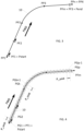
- the present invention relates to a method for defining a trajectory of a laying head 1.
- Said laying head 1 is intended to lay at least one bandage component 2 by winding said bandage component 2 in turns, preferably in turns which are contiguous or partially overlapping from one turn to the next, on a receiving face 4A of a core 4 which is itself driven in rotation around its central axis X4.
- the tire component 2 may be a continuous strip of raw rubber, or even a continuous wire reinforcement element, which has a length much greater, and in particular at least 100 times or even 1000 times greater, than its largest transverse dimension.
- Said continuous wire reinforcement element may be formed for example of a reinforcing wire or cable made of metallic material, fiberglass, or polymer chosen for its tensile strength, such as aramid, said wire or cable possibly being coated with raw rubber.
- said continuous wire reinforcement element may be formed by a reinforcing strip comprising several continuous reinforcing wires or cables, made of metal, fiberglass, or polymer such as aramid, which are arranged parallel to each other in the longitudinal direction of the strip and embedded in a matrix, for example made of raw rubber or resin possibly itself coated with an overlayer of raw rubber.
- the laying head 1 is carried by a robotic arm 5 mounted movably on a base 6.
- Said robotic arm 5 is preferably a six-axis anthropomorphic robotic arm.
- a robotic arm 5 comprises a first joint called “shoulder” forming a connection comprising at least two orthogonal pivot axes between the base 6 and a first segment called “arm” which in turn carries a second joint called “elbow” preferably comprising at least one pivot axis to ensure the angular movement in flexion relative to the arm of a second segment called “forearm", the terminal end of which carries a third joint called “wrist” which is movable along three orthogonal pivot axes two by two, one of which coincides with the axis longitudinal of the forearm, said wrist being designed to receive and carry the laying head 1.
- the robotic arm 5, and therefore the trajectory of the laying head 1, is controlled by an appropriate automatic control unit, of the programmable logic controller type.
- the core 4 is carried by a frame 7 called the “core frame” 7 and driven in rotation around its central axis X4 relative to said core frame 7 by a suitable motorized drive device, preferably provided for this purpose with an electric motor.
- the installation 8 according to the invention which comprises the core 4, the core frame 7 and the robotic arm 5, has several interchangeable laying heads 1, as can be seen in the Figure 1 .
- Each of said laying heads 1 can advantageously be supplied with a different bandage component.
- the robotic arm 5 can thus select the head 2 which corresponds to the bandage component to be laid, and if necessary change the laying head 1 during a manufacturing cycle, in order to be able to successively lay several bandage components on the core 4.
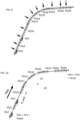
- the receiving face 4A of the core has, along the central axis X4, a predetermined profile 10, as illustrated in the Figure 2 .
- Said profile 10 corresponds to the intersection of the receiving face 4A with a cutting plane called the “meridian plane” which contains the central axis X4.
- the core 4 preferably has a shape of revolution around its central axis X4, and more particularly a toroidal shape, which gives the receiving face 4A a curved profile 10, here of convex curved shape, generally curved outwards.
- said profile 10 comprises a central zone that is almost flat, which corresponds to the top 11 of the bandage that will carry the tread and will come into contact with the road, a central zone that is bordered, at each of its axial ends, by curved zones, the radius of curvature of which is included in a range of values much lower than the range of values of the radius(es) of curvature of the top 11.
- These curved zones that correspond to the shoulders 12, 13 of the bandage, that is to say to the parts of the bandage that form the transition between the apex 11 and the sides of the tire which extend radially towards the central axis X4 to engage on a rim.
- the method for defining a laying trajectory comprises a step (a) of geometric characterization of the profile 10, during which the outline of the profile 10 of the receiving face 4A is provided and a first set of remarkable points PP1, PP2..., PPi..., PPn-1, PPn, called "geometric remarkable points" PP1, PP2..., PPi..., PPn-1, PPn, which are considered characteristic of the shape of said profile 10, and therefore representative of the profile 10, is isolated on this profile 10, and said geometric remarkable points PP1, PP2..., PPi..., PPn-1, PPn are stored in the form of a set of trajectory points called a "trajectory table", as can be seen on the Figure 2 .
- index "n” corresponds to an integer
- "i” denotes the i-th point in the series of points, the value of i being between 1 and n.
- the trajectory table contains at least the spatial coordinates of said geometric remarkable points, expressed in a reference frame attached to the robotic arm 5, and more particularly attached to the fixed base 6 of said robotic arm 5, relative to which the robotic arm 5 executes the movements of the laying head 1.
- the trajectory table i.e. the set of trajectory points
- the trajectory table will take the form of a table, where each trajectory point will form a row of said table.
- the trajectory points and here in particular the rows of the table, will preferably be ordered in accordance with the order in which said trajectory points follow one another along the profile 10, in consideration of a given direction of travel of the profile 10, noted FWD, in which the profile 10 is traveled from one end to the other of said profile 10.
- the trajectory points contained in the trajectory table will preferably be ordered, in said trajectory table, in the direction of the increasing curvilinear abscissas along the profile 10.
- geometric remarkable points PPi are therefore stored here in said trajectory table, preferably in the form of successive lines each corresponding to a remarkable point, in the order which corresponds to the direction of travel FWD.
- the geometric remarkable points PP1, PP2..., PPi..., PPn-1, PPn are all the closer to each other, and therefore the adjacent sections of profile 10 that said geometric remarkable points delimit two by two are all the shorter, as the radius of curvature of the profile 10 is small.
- more geometric remarkable points will be considered, forming a tighter network, in the strongly curved portions of the profile 10, such as the shoulders 12, 13, while said geometric remarkable points will be spaced out in the straighter portions of the profile, such as the top 11.
- the number n of geometric remarkable points provided will preferably be between 20 and 60, more preferably between 30 and 40.
- the method for defining a laying trajectory also comprises a step (b) of functional characterization of the profile 10, during which a plurality of functional zones are determined on the profile 10, each extending from a zone start point to a zone end point, and a laying law is associated with each of said functional zones, which specifies conditions for laying the tire component 2 in the functional zone in question, and said zone start points and said zone end points are inserted, which form a second set of remarkable points PF1, PF2..., PFj..., PFm-1, PFm, called "functional remarkable points” PF1, PF2..., PFj..., PFm-1, PFm, in the trajectory table.
- index "m” corresponds to an integer
- "j" denotes the j-th point in the series of points, the value of j being between 1 and m .
- m can be between 3 and 30, more preferably between 5 and 10.
- the functional remarkable points PF1, PF2..., PFj..., PFm-1, PFm will mark the limits from which, along the profile 10, the execution of a laying law begins, the execution of a laying law ends, or the transition between a first laying law and a second laying law which differs from the first laying law is crossed, and more particularly a second laying law which modifies the value of at least one of the pose parameters, or several of the pose parameters, with respect to said first pose law which precedes it.
- the laying laws will also establish, for example by specifying the laying pitch, a link between on the one hand the angular position and/or the angular speed of the core 4 relative to its central axis X4 and on the other hand the position as well as the evolution of the position of the laying head 1 along the profile 10, to allow control of the movements of the laying head 1 as a function of the angular position of the core 4.
- the laying laws, and therefore the functional remarkable points PFj which characterize them may be initially defined in consideration of the curvilinear abscissa of the profile 10, which amounts to fictitiously considering the profile 10 in a rectilinear developed form, that is to say in the form of a fictitious straight line segment, and to fixing the functional remarkable points PFj as many markers on said fictitious straight line segment.
- the spatial coordinates of the functional remarkable points PFj will then be determined by performing the inverse operation, that is to say by applying the developed, carrying said points, on the real, curved path of the profile 10.
- the second functional remarkable point PF2 indicates the entry into a second functional zone characterized by a modification of a laying parameter, for example a reduction of the laying step, so that a second laying law is applied from said second functional remarkable point PF2, and the third and last functional remarkable point PF3 indicates the arrival point where the laying operation ends, in this case at the end of the second functional zone, and therefore in accordance with the second laying law.
- one or more functional remarkable points PFj may coincide with one or respectively some of the geometric remarkable points PPi.
- at least a portion of the functional remarkable points PFj, where appropriate more than half of the remarkable points functional points PFj, or even all of the functional remarkable points PFj, will in principle be distinct from the geometric remarkable points PPi, insofar as the definition of the laying laws and the adjustments in the successive laying laws, for example in the choice of the bandage component 2 or of the position from which one begins to lay, respectively one stops laying, said bandage component, can in practice be associated with positions on the profile 10 which do not coincide with points of purely geometric definition of the profile 10.
- the successive functional zones are adjacent, so as to continuously cover the profile 10
- the plural generic expression “remarkable points” or “geometric and functional remarkable points” may be used to refer indifferently to both geometric remarkable points PPi and functional remarkable points PFj, and, more particularly, to designate any set which will group or is likely to group both geometric remarkable points PPi and functional remarkable points PFj.
- the generic expression “remarkable point” or “geometric or functional remarkable point” may individually designate a remarkable point which may be indifferently, depending on the context, a geometric remarkable point PPi or a functional remarkable point PPj.
- the method for defining the laying trajectory then comprises, after the identification of the geometric and functional remarkable points PPi, PFj, a meshing step (c) during which, in consideration of a predetermined direction of travel of the profile, noted here FWD, we define on the profile 10, from the first functional remarkable point PF1, that is to say from the start point of the first zone functional, taken as origin, up to the last functional remarkable point PFm, that is to say up to the end point of the last functional zone, a series of virtual points PG1, PG2..., PGk..., PGp-1, PGp, equidistant, called “potential guidance points” PG1, PG2..., PGk..., PGp-1, PGp, which delimit two by two straight line segments all having an identical length, equal to a predetermined chosen value, called “unit resolution step” P_unit, as illustrated in the Figure 4 , and the said potential guidance points PG1, PG2..., PGk..., PGp-1,
- index "p” corresponds to an integer
- "k” denotes the kth point in the series of points.
- the value of the unit resolution step P_unit which separates two by two the potential guide points PG1, PG2..., PGk..., PGp-1, PGp created during the meshing step (c) is between 0.1 mm and 1 mm, for example equal to 0.5 mm.
- the initial number of potential guidance points resulting from the “raw” meshing operation i.e. the number p, could be between 500 (five hundred) and 8,000 (eight thousand), for example between 2,000 and 5,000.
- the raw trajectory table can thus have at least 500 points, at least 1,000 (one thousand) points, or even at least 2,000 (two thousand) points, and sometimes up to 8,000 (eight thousand) trajectory points.
- the method for defining a pose trajectory then comprises, after the meshing step (c), a simplification step (d) during which the size of the trajectory table is reduced by applying to the trajectory table one or more selection criteria in order to select at least a part, and only a part, of the potential guidance points PGk and the geometric and functional remarkable points PPi, PFj contained in the trajectory table, and by eliminating the unselected points, so as to obtain, as can be seen on the Figure 10 , a simplified trajectory table 20, of reduced size, within which at least one and preferably several of the (straight) segments which connect two by two the successive selected points have a length strictly greater than the unit resolution step P_unit chosen.
- trajectory points will be retained, and more particularly the potential guidance points PGk, which correspond to singularities of the profile 10 or of the pose law, in order to concentrate the precision, and therefore the available computing power, in the portions of the profile 10 which truly require it.
- each selection criterion can be considered as a sub-step of step (d) of simplification.
- the potential guidance points PGk appear dotted on the figures 3 to 10 , and the points actually selected, and therefore present in the trajectory table at the time considered, are indicated by small circles in a continuous line with a hollow central part. Arrows indicate the points which are added to the selection (also called “list of selected points") during the sub-step considered, depending on the selection criterion applied.
- one, in this case a first, selection criterion by framing is applied, according to which, as is visible on the Figure 5 , we select the first functional remarkable point PF1, considered as the starting point Pstart of the laying trajectory, we select the last functional remarkable point PFm, considered as the arrival point Pend of the laying trajectory, and, for at least one geometric or functional point PPi, PFj which is strictly between the starting point Pstart and the arrival point Pend, and more preferably for each geometric or functional remarkable point PPi, PFj which is strictly between the starting point Pstart and the arrival point Pend, namely here in this order PF2, PP2 then PP3 on the example of the Figure 5 , we select, from among the two potential guidance points PGk which frame said remarkable geometric or functional point PPi, PFj, that is to say from among the potential guidance point which immediately precedes and the potential guidance point which immediately follows said remarkable geometric or functional point PPi, PFj, at least one of
- each remarkable point PPi, PFj which is strictly between the starting point Pstart and the arrival point Pend, we select each of the two potential guidance points PGk which frame the geometric or functional remarkable point PPi, PFj considered, that is to say which for one immediately precedes and for the other immediately follows said geometric or functional remarkable point PPi, PFj.
- all the geometric and functional remarkable points PPi, PFj strictly included between the starting point Pstart and the arrival point Pend will be the subject of a framework by one or preferably by two potential guidance points PGk according to this first selection criterion, so that we will thus be led to delete all said geometric and functional remarkable points PPi, PFj strictly included between the starting point Pstart and the arrival point Pend.
- deletion amounts to "de-selecting" all the remarkable points PPi, PFj which are concerned by the selection criterion by framing, and therefore to deleting from the trajectory table at least part of, and preferably all of, the geometric and functional remarkable points PPi, PFj which are strictly included between the starting point Pstart and the arrival point Pend.
- Such a deletion operation is advantageously made possible by the fact that the potential guidance point or, even more so, the two potential guidance points PGk selected in the vicinity of each geometric or functional remarkable point PPi, PFj concerned are chosen from the two potential guidance points PGk which frame said remarkable point PPi, PFj and which are both located at a very short distance from said remarkable point, in this case at a distance which is strictly less than the unit resolution step P_unit, so that it is not useful to keep the remarkable point PPi, PFj to satisfy the desired precision requirement.
- the deletion of the remarkable points PPi, PFj framed by selected potential guidance points PGk is preferably immediate, so that said remarkable points PPi, PFj no longer participate as such in the subsequent selection of the trajectory points when applying the selection criteria which follow the application of the selection criterion by framing.
- the last functional remarkable point PFm coincide exactly with one of the virtual guidance points PGk, and that in addition it is desirable to ensure the precision of the end of the laying operation, in particular in order to avoid a possible overshoot of the setpoint or an excessively abrupt slowing down of the laying head 1, it will also be preferable to select, still according to this same framing criterion, the virtual guidance point PGk which immediately precedes the last functional remarkable point PFm, here therefore PG29 on the Figure 5 , while also retaining, as indicated above, the said last functional remarkable point PFm, which constitutes the arrival point Pend.
- a, here a second, selection criterion is applied, namely a selection criterion by authorized deviation limit, according to which we consider, for each pair of adjacent straight line segments defined by each trio of successive points already selected, for example the trio PG13, PG21, PG22 on the figures 5 to 7 , the interpolating circle Ck which passes through the three points of said trio, and, for each of the two straight line segments 21 delimited by two successive points of said trio of points, we calculate the arrow D between said straight line segment 21, forming the chord of the arc 21, and the arc 22 of the interpolating circle which corresponds to it, that is to say the greatest distance D measured perpendicular to the straight line segment 21 and which separates the arc 22 from said straight line segment 21, as illustrated in the Figure 6 , and, if said arrow D calculated for said segment 21 exceeds a predefined maximum authorized deviation value Dmax
- the potential guidance point PGk which is located closest to the middle of the line segment 21 concerned is added to the list of selected points.
- this is the potential guidance point PG17.
- a, here a third, selection criterion is applied, namely a selection criterion by maximum authorized segment length, according to which, as is visible on the figure 8 , we calculate the length L21 of each straight line segment 21 having as its ends two successive already selected points and, if said calculated length L21 exceeds a predefined maximum authorized length value Lmax, we add to the list of selected points one of the potential guide points PGk which are strictly between the two points forming the ends of the segment 21 considered, as can be seen on the figure 8 .
- the potential guidance point PGk which forms with the potential guidance point PGk forming the start end of the segment 21 concerned the largest segment whose length remains less than or equal to the maximum authorized length value Lmax, as can be seen on the figure 8 , or, alternatively, the potential guidance point PGk which is located closest to the middle of the line segment 21 concerned.
- the maximum permitted length value Lmax may be set as a distance, or possibly, in a substantially equivalent manner, as the maximum permitted number of potential guidance points not yet selected present between two points already selected, i.e. as the size of the “empty” mesh space between two points already selected.
- the maximum authorized length Lmax chosen may be between 10 mm and 50 mm.
- a fourth, selection criterion is applied, namely a selection criterion by degree of quality, according to which one adds to the points already selected the N potential guidance points which immediately precede and the N potential guidance points which immediately follow each of said points already selected, N being an integer, preferably equal to zero by default, the value of which is set by the user.
- the value of N will preferably be adjusted empirically, and more particularly increased, for example brought to the value 1 or 2, preferably as a function of a test during which a bandage is manufactured using the simplified trajectory table obtained following the application of the preceding criterion(s), here the first, second and third selection criteria, then the quality of the bandage obtained is evaluated and, if said quality is deemed insufficient, the value N is increased by one unit.
- This selection criterion by degree of quality will advantageously improve the quality of the finish, in particular the appearance of the bandage and the quality of the junction between successive turns, in particular in the portions of the profile 30 which are affected by changes of direction (turns).
- All points that have not been selected after applying the selection criterion(s) are then eliminated.
- at least all potential guidance points PGk that have not been selected are thus deleted, and preferably both the potential guidance points PGk that have not been selected and the remarkable points, geometric PPi and functional PFj, that have not been selected.
- the number of trajectory points finally selected, and therefore the total number of trajectory points stored, in the form of table lines, in the simplified trajectory table 20, is preferably between 150 (one hundred and fifty) points and 1,000 (one thousand) points.
- the reduction ratio which is equal to the ratio between the size of the simplified trajectory table 20 obtained after application of the selection criteria and the size of the “raw” trajectory table resulting from the meshing step (c), i.e. the ratio between the number of trajectory points finally selected and therefore contained in the simplified trajectory table 20 on the one hand and the maximum potential number of trajectory points represented by the sum of all the remarkable points PPi, PFj and all the potential guidance points Gk initially available at the end of the raw meshing step (c) on the other hand, is preferably substantially between 1/10 and 1/30, i.e. a reduction in the size of the trajectory table by a factor of 10, 20, or even 30.
- the method according to the invention is therefore particularly effective in reducing the control of the laying head 1 while maintaining excellent control of the laying trajectory.
- the invention relates as such to a method of manufacturing a bandage during which a simplified trajectory table 20 is established in accordance with a trajectory definition method according to any one of the possibilities described above, and the simplified trajectory table 20 is transmitted to a robotic arm 5 carrying the laying head 1, so that said robotic arm 5 executes said simplified trajectory table 20 using as instructions the succession of segments which connect the successive selected points stored in said simplified trajectory table 20.
- the simplified trajectory table 20 associates each of its selected points with an absolute rotation angle of the core 4, and during the rotation of the core 4 around its central axis X4, the absolute rotation angle traveled in rotation by said core 4 from a predefined origin is measured, and the position conferred by the robotic arm 5 to the laying head 1 is slaved to the rotation angle of the core.
- the simplified trajectory table 20 may advantageously be presented for this purpose in the form of a table comprising the points stored in the form of lines and whose input value, typically the value stored in the first column of each line, will indicate the rotation angle corresponding to the point considered.
- the angular position of the core can be encoded by any suitable sensor associated with the central axis X4, such as a resolver type encoder.
- Each line will preferably include the target coordinates (X, Y, Z) of the laying head 1 expressed in each of the three axes of the Cartesian reference frame (X5, Y5, Z5) attached to the base 6 of the robotic arm 5, as well as, where appropriate, the angular orientation (W, P, R) of the laying head 1 in yaw, roll, and possibly pitch, in said reference frame.
- the "roll” will allow the laying head to tilt laterally (here around the axis Y4, with which the axis Y5 merges) to remain tangent to the curvature of the profile 10 such that this curvature is drawn in a meridian plane containing the central axis X4 and passing through the point of contact between the laying head 1 and the receiving face 4A of the core 4, while the "yaw” will correspond to the rotation around the axis (here radial, and more particularly vertical) which is normal to the receiving face 4A at the point of contact between the laying head 1 and said receiving face 4A, and will allow the bandage component 2 to be oriented so that the longitudinal direction of said bandage component 2 coincides with the direction formed by the desired helix angle for the winding relative to the circumferential direction of the core 4.
- the control unit establishes, in accordance with the trajectory definition method described above, a simplified trajectory table 20, then transmits the simplified trajectory table 20 to the robotic arm 5, and requests said robotic arm 5 to execute the tracking of the points contained in said simplified trajectory table 20.
- the robotic arm 5 has a basic intelligence, that is to say its own means of calculation and data storage, existing but limited, which allow it to execute, in the form of linear segments, a point-to-point instruction tracking provided in the form of a trajectory table.
- the control unit having calculated the angular position of the core 4 which must be reached to begin the laying operation, that is to say the angular position which corresponds to the starting point Pstart of the first functional zone, said control unit starts the rotation of the core 4.
- the robotic arm 5 reads the angular position of the core 4 using the encoder.
- the robotic arm 5 searches in the simplified trajectory table 20 for the line at which it is located, and therefore the setpoint coordinates applicable at the instant in question.
- the robotic arm 5 reads, in its own reference system (X5, Y5, Z5), the coordinates X, Y, Z, W, P and R which correspond to its effective position, and more particularly to the effective position and orientation of the laying head 1.
- the robotic arm 5 determines, by comparing the setpoint coordinates provided by the line of the simplified trajectory table 20 on the one hand with the coordinates of its own effective position on the other hand, what distance (linear on the X5, Y5, Z5 positioning axes, angular for the orientation rotations in roll, yaw, or even pitch) it must travel to reach the X, Y, Z, W, P and R coordinates entered in the simplified trajectory table.
- the robotic arm 5 then executes a linear movement to reach the setpoint coordinates, i.e. to reach the trajectory point specified in the simplified trajectory table, and therefore place the laying head 1 in the desired configuration.
- This cycle starts again until the core 4 reaches the calculated final angular position, i.e. the arrival point Pend of the pose trajectory, at the end of the last functional zone, and the robotic arm 5 consequently reaches the last point (here the last line) of its simplified trajectory table 20.
- the manufacturing method may comprise, preferably prior to the execution of the simplified trajectory table 20, and more generally prior to the execution of any trajectory table, a calibration step during which, by means of a laser tacheometer mounted on a station which is located at a chosen reference location, and which is distinct from the frame 7 called the “core frame” 7 which carries the core 4 and the device for driving said core 4 in rotation, and which is also distinct from the base 6 of the robotic arm 5, the position of three target points of the core frame 7 is measured, in order to identify a first Cartesian reference frame (X4, Y4, Z4), called the “core reference frame”, attached to the core frame, relative to the location of the station of the core frame 7.
- a calibration step during which, by means of a laser tacheometer mounted on a station which is located at a chosen reference location, and which is distinct from the frame 7 called the “core frame” 7 which carries the core 4 and the device for driving said core 4 in rotation, and which is also distinct from the base 6 of the robotic arm 5, the position of three target points
- a target such as a cube corner
- the robotic arm 5 is moved so as to successively position said target at three different points in space, and the position of said target is measured each time so as to identify, relative to the same location of the laser tacheometer station, a second Cartesian reference frame (X5, Y5, Z5), called the "robot reference frame", attached to the robotic arm 5, and more precisely to the fixed base 6 of said robotic arm 5, and the robotic arm 5 is calibrated so as to superimpose the robot reference frame (X5, Y5, Z5) with the core reference frame (X4, Y4, Z4), and thus make the orthonormal axes of said reference frames coincide: X4 with X5, Y4 with Y5, Z4 with Z5.
Landscapes
- Engineering & Computer Science (AREA)
- Mechanical Engineering (AREA)
- Tyre Moulding (AREA)
Claims (12)
- Verfahren zur Steuerung eines Verlegekopfes (1), wobei der Verlegekopf (1) dazu bestimmt ist, mindestens eine Reifenkomponenten (2) durch Wickeln der Reifenkomponente (2) in Windungen auf eine Aufnahmeseite (4A) eines Kerns (4) zu verlegen, der um seine zentrale Achse (X4) drehangetrieben wird, wobei die Aufnahmeseite (4A), entlang der zentralen Achse, ein vorbestimmtes Profil (10) aufweist, wobei das Verfahren dadurch gekennzeichnet ist, dass es umfasst:- einen Schritt (a) zur geometrischen Charakterisierung des Profils, bei dem der Verlauf des Profils (10) der Aufnahmeseite (4A) ausgegeben wird und an diesem Profil (10) ein erster Satz von Kennpunkten, "geometrische Kennpunkte" (PP1, PP2..., PPi..., PPn-1, PPn) genannt, die als charakteristisch für die Form des Profils (10) erachtet werden, isoliert wird, und die geometrischen Kennpunkte (PP1, PP2..., PPi..., PPn-1, PPn) in Form eines Trajektorienpunktesatzes, "Trajektorientabelle" genannt, gespeichert werden,- einen Schritt (b) zur funktionalen Charakterisierung des Profils, bei dem an dem Profil eine Mehrzahl von funktionalen Bereichen bestimmt wird, die sich jeweils von einem Bereichsstartpunkt bis zu einem Bereichsendpunkt erstrecken, und jedem der funktionalen Bereich ein Verlegegesetz zugeordnet wird, das Verlegebedingungen der Reifenkomponente in dem betrachteten funktionalen Bereich spezifiziert, und die Bereichsstartpunkte und die Bereichsendpunkte, die einen zweiten Satz von Kennpunkten, "funktionale Kennpunkte" (PF1, PF2..., PFj..., PFm-1, PFm) genannt, in die Trajektorientabelle eingefügt werden,- dann einen Schritt (c) zur Vermaschung, bei dem, unter Berücksichtigung einer vorbestimmten Laufrichtung (FWD) des Profils, an dem Profil (10), von dem ersten funktionalen Kennpunkt (PF1) aus, d. h. von dem Anfangspunkt des ersten funktionalen Bereichs aus, der als Ursprung genommen wird, bis zu dem letzten funktionalen Kennpunkt (PFm), d. h. bis zu dem Endpunkt des letzten funktionalen Bereichs, eine Reihe von äquidistanten virtuellen Punkten (PG1, PG2..., PGk..., PGp-1, PGp), "potentielle Führungspunkte" (PG1, PG2..., PGk..., PGp-1, PGp) genannt, definiert wird, die paarweise Geradensegmente begrenzen, die alle eine identische Länge gleich einem vorbestimmten gewählten Wert, "einheitliche Auflösungsschrittweite" (P_unit) genannt, aufweisen, und die potentiellen Führungspunkte (PG1, PG2..., PGk..., PGp-1, PGp) in die Trajektorientabelle eingefügt werden,- dann einen Schritt (d) zur Vereinfachung, bei dem die Größe der Trajektorientabelle verringert wird, indem auf die Trajektorientabelle ein oder mehrere Auswahlkriterien angewandt werden, um mindestens einen Teil, und nur einen Teil, der potentiellen Führungspunkte (PGk) und der geometrischen und funktionalen Kennpunkte (PPi, PFj) auszuwählen, die in der Trajektorientabelle enthalten sind, und indem die nicht ausgewählten Punkte entfernt werden, so dass eine vereinfachte Trajektorientabelle (20) mit verringerter Größe erhalten wird, in der mindestens eines und bevorzugt mehrere der Segmente, die die aufeinander folgenden ausgewählten Punkte paarweise verbinden, eine Länge aufweisen, die strikt größer als die gewählte einheitliche Auflösungsschrittweite (P_unit) ist.
- Verfahren nach Anspruch 1, dadurch gekennzeichnet, dass bei dem Schritt (d) zur Vereinfachung ein Kriterium zur Auswahl durch Einrahmung angewandt wird, gemäß dem der erste funktionale Kennpunkt (PF1) ausgewählt wird, der als Startpunkt (Pstart) der Verlegetrajektorie betrachtet wird, der letzte funktionale Kennpunkt (PFm) ausgewählt wird, der als Zielpunkt (Pend) der Verlegetrajektorie betrachtet wird, und für mindestens einen und bevorzugt für jeden geometrischen oder funktionalen Kennpunkt (PPi, PFj), der strikt zwischen dem Startpunkt (Pstart) und dem Zielpunkt (Pend) enthalten ist, unter den beiden potentiellen Führungspunkten (PGk), die den geometrischen oder funktionalen Kennpunkt (PPi, PFj) einrahmen, d. h. unter dem potentiellen Führungspunkt, der unmittelbar vorausgeht, und dem potentiellen Führungspunkt, der dem geometrischen oder funktionalen Kennpunkt (PPi, PFj) unmittelbar folgt, mindestens einer der beiden potentiellen Führungspunkte (PGk) ausgewählt wird, zum Beispiel derjenige der beiden Führungspunkte (PGk), der dem betrachteten geometrischen oder funktionalen Kennpunkt (PPi, PFj) am nächsten ist.
- Verfahren nach Anspruch 2, dadurch gekennzeichnet, dass für mindestens einen beziehungsweise für jeden geometrischen oder funktionalen Kennpunkt (PPi, PFj), der strikt zwischen dem Startpunkt (Pstart) und dem Zielpunkt (Pend) enthalten ist, jeder der beiden potentiellen Führungspunkte (PGk) ausgewählt wird, die den geometrischen oder funktionalen Kennpunkt (Ppi, PFj) einrahmen, d. h. von denen einer ihm unmittelbar vorausgeht und der andere ihm unmittelbar folgt.
- Verfahren nach Anspruch 2 oder Anspruch 3, dadurch gekennzeichnet, dass, nachdem gemäß dem Kriterium zur Auswahl durch Einrahmung der oder die potentiellen Führungspunkte (PGk) ausgewählt wurden, die einen geometrischen oder funktionalen Kennpunkt (PPi, PFj) einrahmen, der strikt zwischen dem Startpunkt (Pstart) und dem Zielpunkt (Pend) enthalten ist, der betreffende geometrische oder funktionale Kennpunkt (PPi, PFj) gelöscht wird.
- Verfahren nach einem der vorhergehenden Ansprüche, dadurch gekennzeichnet, dass bei dem Schritt (d) zur Vereinfachung ein Kriterium zur Auswahl nach einem Grenzwert der zulässigen Abweichung angewandt wird, gemäß dem für jedes Paar aus benachbarten Geradensegmenten, die durch jedes Trio aus bereits ausgewählten aufeinander folgenden Punkten definiert werden, der interpolierende Kreis (Ck), der durch die drei Punkte des Trios verläuft, berücksichtigt wird und für jedes der beiden Geradensegmente (21), die durch zwei aufeinander folgende Punkte des Punktetrios begrenzt werden, die Pfeilhöhe (D) zwischen dem Geradensegment (21), das die Bogensehne bildet, und dem Bogen (22) des ihr entsprechenden interpolierenden Kreises berechnet wird und, wenn die für das Segment (21) berechnete Pfeilhöhe (D) einen vorgegebenen zulässigen maximalen Abweichungswert (Dmax) überschreitet, zu der Liste der ausgewählten Punkte der oder einer der potentiellen Zwischenführungspunkte (PGk) hinzugefügt wird, die zwischen den potentiellen Führungspunkten liegen, die die Enden des betrachteten Segments (21) bilden, bevorzugt der potentielle Führungspunkt (PGk), der dem Mittelpunkt des betrachteten Geradensegments (21) am nächsten liegt.
- Verfahren nach einem der vorhergehenden Ansprüche, dadurch gekennzeichnet, dass bei dem Schritt (d) zur Vereinfachung ein Kriterium zur Auswahl nach der zulässigen maximalen Segmentlänge angewandt wird, gemäß dem die Länge (L21) jedes Geradensegments (21) berechnet wird, das als Enden zwei aufeinander folgende bereits ausgewählte Punkte hat, und, wenn die berechnete Länge (L21) den vorgegebenen zulässigen maximalen Längenwert (Lmax) übersteigt, zu der Liste der ausgewählten Punkte einer der potentiellen Führungspunkte (PGk) hinzugefügt wird, die sich strikt zwischen den beiden Punkten befinden, die die Enden des betrachteten Segments (21) bilden, bevorzugt entweder der potentielle Führungspunkt (PGk), der mit dem potentiellen Führungspunkt, der das Anfangsende des betreffenden Segments bildet, das größte Segment bildet, dessen Länge kleiner als oder gleich dem zulässigen maximalen Längenwert (Lmax) bleibt, oder der potentielle Führungspunkt (PGk), der dem Mittelpunkt des betreffenden Geradensegments (21) am nächsten liegt.
- Verfahren nach einem der vorhergehenden Ansprüche, dadurch gekennzeichnet, dass bei dem Schritt (d) zur Vereinfachung ein Kriterium zur Auswahl nach dem Qualitätsgrad angewandt wird, gemäß dem zu den bereits ausgewählten Punkten die N potentiellen Führungspunkte (PGk) hinzugefügt werden, die unmittelbar vorausgehen, und die N potentiellen Führungspunkte (PGk), die auf jeden der bereits ausgewählten Punkte unmittelbar folgen, wobei N eine ganze Zahl ist, die bevorzugt standardmäßig den Wert null hat und deren Wert von dem Benutzer festgelegt wird, wobei der Wert von N bevorzugt empirisch angepasst werden kann und insbesondere erhöht werden kann, zum Beispiel auf den Wert 1 oder 2 gebracht werden kann, vorzugsweise in Abhängigkeit von einem Test, bei dem die Herstellung eines Reifens unter Verwendung der vereinfachten Trajektorientabelle vorgenommen wird, die nach der Anwendung des oder der vorhergehenden Kriterien erhalten wird, die Qualität des erhaltenen Reifens bewertet wird und, wenn die Qualität als ungenügend erachtet wird, der Wert N um eine Einheit inkrementiert wird.
- Verfahren nach einem der vorhergehenden Ansprüche, dadurch gekennzeichnet, dass der Wert der einheitlichen Auflösungsschrittweite (P_unit), die die potentiellen Führungspunkte (PG1, PG2..., PGk..., PGp-1, PGp) paarweise trennt, die bei dem Schritt (c) zur Vermaschung erzeugt werden, zwischen 0,1 mm und 1 mm liegt, zum Beispiel 0,5 mm beträgt.
- Verfahren nach einem der vorhergehenden Ansprüche, dadurch gekennzeichnet, dass bei dem Schritt (b) zur funktionalen Charakterisierung des Profils jedem der funktionalen Bereiche ein Verlegegesetz zugeordnet wird, das die Verlegebedingungen der Reifenkomponente (2) in dem betrachteten funktionalen Bereich charakterisiert, indem der in dem betrachteten Bereich anwendbare und konstante Wert mindestens eines Verlegeparameters und bevorzugt mehrerer Verlegeparameter spezifiziert wird unter: (i) der Art der Reifenkomponente, (ii) der Verlegeschrittweite, gemäß welcher der Verlegekopf (1) in Bezug auf den Kern (4) entlang der zentralen Achse (X4) zwischen zwei aufeinander folgenden Windungen versetzt wird, (iii) der Verlegegeschwindigkeit, die der Umfangsgeschwindigkeit des Kerns (4) entspricht, mit der die Reifenkomponente (2) auf den Kern gewickelt wird, und/oder (iv) der Verlegespannung, die der Längszugkraft entspricht, die innerhalb der Reifenkomponente (2) beim Verlegen unter der Zugwirkung des drehenden Kerns (4) ausgeübt wird.
- Verfahren zur Herstellung eines Reifens, bei dem eine vereinfachte Trajektorientabelle (20) gemäß dem Verfahren zur Steuerung eines Verlegekopfes nach einem der Ansprüche 1 bis 9 erstellt wird und die vereinfachte Trajektorientabelle (20) an einen Roboterarm (5) übertragen wird, der den Verlegekopf (1) trägt, so dass der Roboterarm (5) die vereinfachte Trajektorientabelle (20) ausführt, indem er als Sollwert die Abfolge von Segmenten verwendet, welche die aufeinander folgenden ausgewählten Punkte verbinden, die in der vereinfachten Trajektorientabelle gespeichert sind.
- Verfahren zur Herstellung eines Reifens nach Anspruch 10, dadurch gekennzeichnet, dass die vereinfachte Trajektorientabelle (20) jeden ihrer ausgewählten Punkte einem absoluten Drehwinkel des Kerns zuordnet, dadurch, dass bei der Drehung des Kerns (4) um seine zentrale Achse (X4) der absolute Drehwinkel gemessen wird, der von dem Kern von einem vorgegebenen Ursprung aus drehend zurückgelegt wird, und dadurch, dass die Position, die dem Verlegekopf (1) von dem Roboterarm (5) verliehen wird, in Abhängigkeit von dem Drehwinkel des Kerns geregelt wird.
- Verfahren zur Herstellung eines Reifens nach Anspruch 10 oder 11, dadurch gekennzeichnet, dass es einen Schritt zur Kalibrierung umfasst, bei dem mittels eines Laser-Tachymeters, das auf einer Station montiert ist, die an einer gewählten Referenzposition gelegen ist und die von dem Gestell (7), "Kerngestell" (7) genannt, das den Kern (4) und die Drehantriebsvorrichtung des Kerns trägt, verschieden ist und von dem Sockel (6) des Roboterarms (5) verschieden ist, die Lage von drei Zielpunkten des Kerngestells gemessen wird, um ein erstes kartesisches Koordinatensystem (X4, Y4, Z4), "Koordinatensystem des Kerns" genannt, das dem Kerngestell (7) zugewiesen ist, in Bezug auf die Position der Station des Laser-Tachymeters zu identifizieren, dann ein Ziel wie eine Würfelecke an der Position des Roboterarms (5), der zum Aufnehmen des Verlegekopfes (1) bestimmt ist, befestigt wird, der Roboterarm (5) so bewegt wird, dass das Ziel nacheinander an drei verschiedenen Punkten des Raums positioniert wird, und jedes Mal die Lage des Ziels gemessen wird, so dass in Bezug auf dieselbe Position der Station des Laser-Tachymeters ein zweites kartesisches Koordinatensystem (X5, Y5, Z5), "Koordinatensystem des Roboters" genannt, das dem Roboterarm (5) zugewiesen ist, identifiziert wird, und der Roboterarm (5) so kalibriert wird, dass das Koordinatensystem des Roboters (X5, Y5, Z5) mit dem Koordinatensystem des Kerns (X4, Y4, Z4) überlagert wird und so die orthonormierten Achsen der Koordinatensysteme in Übereinstimmung gebracht werden.
Applications Claiming Priority (2)
| Application Number | Priority Date | Filing Date | Title |
|---|---|---|---|
| FR2013656A FR3117924B1 (fr) | 2020-12-18 | 2020-12-18 | Procédé de pilotage d’une tête de pose de composant de bandage avec simplification de trajectoire |
| PCT/FR2021/051852 WO2022129708A1 (fr) | 2020-12-18 | 2021-10-21 | Procédé de pilotage d'une tête de pose de composant de bandage avec simplification de trajectoire |
Publications (2)
| Publication Number | Publication Date |
|---|---|
| EP4263196A1 EP4263196A1 (de) | 2023-10-25 |
| EP4263196B1 true EP4263196B1 (de) | 2025-05-28 |
Family
ID=75746752
Family Applications (1)
| Application Number | Title | Priority Date | Filing Date |
|---|---|---|---|
| EP21810660.7A Active EP4263196B1 (de) | 2020-12-18 | 2021-10-21 | Verfahren zur steuerung eines verlegekopfs einer reifenkomponente mit vereinfachtem weg |
Country Status (5)
| Country | Link |
|---|---|
| US (1) | US20240034016A1 (de) |
| EP (1) | EP4263196B1 (de) |
| CN (1) | CN116635224B (de) |
| FR (1) | FR3117924B1 (de) |
| WO (1) | WO2022129708A1 (de) |
Family Cites Families (5)
| Publication number | Priority date | Publication date | Assignee | Title |
|---|---|---|---|---|
| DE69919233T3 (de) * | 1999-11-19 | 2010-12-30 | Pirelli Tyre S.P.A. | Verfahren zur herstellung von reifenbestandteilen aus elastomerischem material |
| DE602004004040T2 (de) * | 2003-11-21 | 2007-08-09 | Société de Technologie Michelin | Vorrichtung und Verfahren zum Auflegen eines endlosen Streifens auf eine torusförmige Oberfläche. |
| US8535465B2 (en) * | 2007-11-30 | 2013-09-17 | Pirelli Tyre S.P.A. | Process and apparatus for manufacturing tyres for vehicle wheels |
| WO2010073055A1 (en) * | 2008-12-22 | 2010-07-01 | Pirelli Tyre S.P.A. | Tyre for two -wheeled vehicle and process for manufacturing the same |
| NL2021086B1 (en) * | 2018-06-08 | 2019-12-13 | Vmi Holland Bv | Tire building method and tire building system, in particular for strip-winding |
-
2020
- 2020-12-18 FR FR2013656A patent/FR3117924B1/fr active Active
-
2021
- 2021-10-21 WO PCT/FR2021/051852 patent/WO2022129708A1/fr not_active Ceased
- 2021-10-21 EP EP21810660.7A patent/EP4263196B1/de active Active
- 2021-10-21 CN CN202180084530.7A patent/CN116635224B/zh active Active
- 2021-10-21 US US18/266,420 patent/US20240034016A1/en active Pending
Also Published As
| Publication number | Publication date |
|---|---|
| FR3117924A1 (fr) | 2022-06-24 |
| FR3117924B1 (fr) | 2023-06-02 |
| EP4263196A1 (de) | 2023-10-25 |
| CN116635224A (zh) | 2023-08-22 |
| WO2022129708A1 (fr) | 2022-06-23 |
| US20240034016A1 (en) | 2024-02-01 |
| CN116635224B (zh) | 2025-11-18 |
Similar Documents
| Publication | Publication Date | Title |
|---|---|---|
| EP2655713B1 (de) | Verfahren zum verflechten von verstärkungsfasern unter veränderung der neigung der verflochtenen fasern | |
| EP0582215B1 (de) | Verfahren zum Herstellen von Reifen und Vorrichtung zum Herstellen einer Reifengürtelverstärkung | |
| FR2620081A3 (fr) | Machine a poser des bandes pour la realisation d'une structure stratifiee de materiau composite sur une forme de pose de contour complexe et procede de fabrication d'une telle structure stratifiee | |
| EP1517781B1 (de) | Vorrichtung zur herstellung einer verstärkungsstruktur für einen reifen mit einem wulstfahnendrehmechanismus | |
| WO2014006094A1 (fr) | Procede et appareil de pilotage de faisceau laser pour la fabrication d'objets tridimensionnels par couches superposees | |
| EP4263196B1 (de) | Verfahren zur steuerung eines verlegekopfs einer reifenkomponente mit vereinfachtem weg | |
| FR2915704A1 (fr) | Tete de drapage de composite avec dispositif escamotable de separation de preimpregne de son ruban de support. | |
| EP2199069A1 (de) | Herstellung von komplexen Verbundwerkstücken | |
| EP1513672B1 (de) | Herstellung einer reifenverstärkungsstruktur mit der volumenregelung der matrix | |
| EP2616231A1 (de) | Vereinfachtes verfahren zur herstellung einer aufhängefeder eines kraftfahrzeuges aus einem verbundstoff | |
| EP2613928B1 (de) | Verfahren und vorrichtung zur herstellung eines reifenrohlings mittels eines streifens | |
| EP0718245B1 (de) | Vorrichtung zum Herstellen oder Beschichten einer Vorform mit einer Einrichtung zum Unterstützen der Vorform und Verfahren wobei eine solche Vorrichtung benützt wird | |
| EP1426170B1 (de) | Vorrichtung mit mehreren Auftragungsarmen zur Herstellung eines Verstärkungselements für Luftreifen | |
| WO2019106322A1 (fr) | Procede de fabrication de laizes pour nappe de renfort de pneumatique par aboutage de bandelettes droit fil | |
| CA3205108A1 (fr) | Tete de depose pour une installation d'enroulement filamentaire | |
| EP0930551B1 (de) | Verfahren zur Steuerung der Absetzung eines Bündels durch Umwickeln oder Kontakt auf grossvolumigen Körpern und Maschine dafür | |
| CA3205783A1 (fr) | Porte bobine pilote pour une installation d'enroulement filamentaire | |
| EP0728117B1 (de) | Verfahren zur versetzten anordnung der lagen einer wicklung | |
| EP0682481A1 (de) | Verfahren zum automatischen schneiden von weichen blattmaterialien | |
| EP3894202B1 (de) | Vorrichtung und verfahren zur positionierung einer karkassenlage auf eine reifenaufbautrommel mit synchronem schneiden | |
| WO2025224258A1 (fr) | Procédé de fabrication d'un élément composite 3d | |
| WO2007080254A1 (fr) | Machine mixte et procédé de placement de rubans et de nappage | |
| FR3139751A1 (fr) | Procédé de fabrication sur un noyau d’un bandage pneumatique dont la carcasse comprend des renforts qui sont inclinés dans les flancs et radiaux sous le sommet | |
| EP1279484A1 (de) | Vorrichtung zur Herstellung einer Reifenverstärkungsstruktur | |
| FR2477045A1 (fr) | Procede et appareillage pour la fabrication de ressorts miniblocs |
Legal Events
| Date | Code | Title | Description |
|---|---|---|---|
| STAA | Information on the status of an ep patent application or granted ep patent |
Free format text: STATUS: UNKNOWN |
|
| STAA | Information on the status of an ep patent application or granted ep patent |
Free format text: STATUS: THE INTERNATIONAL PUBLICATION HAS BEEN MADE |
|
| PUAI | Public reference made under article 153(3) epc to a published international application that has entered the european phase |
Free format text: ORIGINAL CODE: 0009012 |
|
| STAA | Information on the status of an ep patent application or granted ep patent |
Free format text: STATUS: REQUEST FOR EXAMINATION WAS MADE |
|
| 17P | Request for examination filed |
Effective date: 20230718 |
|
| AK | Designated contracting states |
Kind code of ref document: A1 Designated state(s): AL AT BE BG CH CY CZ DE DK EE ES FI FR GB GR HR HU IE IS IT LI LT LU LV MC MK MT NL NO PL PT RO RS SE SI SK SM TR |
|
| DAV | Request for validation of the european patent (deleted) | ||
| DAX | Request for extension of the european patent (deleted) | ||
| GRAP | Despatch of communication of intention to grant a patent |
Free format text: ORIGINAL CODE: EPIDOSNIGR1 |
|
| STAA | Information on the status of an ep patent application or granted ep patent |
Free format text: STATUS: GRANT OF PATENT IS INTENDED |
|
| INTG | Intention to grant announced |
Effective date: 20240912 |
|
| GRAJ | Information related to disapproval of communication of intention to grant by the applicant or resumption of examination proceedings by the epo deleted |
Free format text: ORIGINAL CODE: EPIDOSDIGR1 |
|
| STAA | Information on the status of an ep patent application or granted ep patent |
Free format text: STATUS: REQUEST FOR EXAMINATION WAS MADE |
|
| GRAP | Despatch of communication of intention to grant a patent |
Free format text: ORIGINAL CODE: EPIDOSNIGR1 |
|
| STAA | Information on the status of an ep patent application or granted ep patent |
Free format text: STATUS: GRANT OF PATENT IS INTENDED |
|
| INTC | Intention to grant announced (deleted) | ||
| RAP3 | Party data changed (applicant data changed or rights of an application transferred) |
Owner name: COMPAGNIE GENERALE DES ETABLISSEMENTS MICHELIN |
|
| INTG | Intention to grant announced |
Effective date: 20250115 |
|
| GRAS | Grant fee paid |
Free format text: ORIGINAL CODE: EPIDOSNIGR3 |
|
| GRAA | (expected) grant |
Free format text: ORIGINAL CODE: 0009210 |
|
| STAA | Information on the status of an ep patent application or granted ep patent |
Free format text: STATUS: THE PATENT HAS BEEN GRANTED |
|
| AK | Designated contracting states |
Kind code of ref document: B1 Designated state(s): AL AT BE BG CH CY CZ DE DK EE ES FI FR GB GR HR HU IE IS IT LI LT LU LV MC MK MT NL NO PL PT RO RS SE SI SK SM TR |
|
| REG | Reference to a national code |
Ref country code: GB Ref legal event code: FG4D Free format text: NOT ENGLISH |
|
| REG | Reference to a national code |
Ref country code: CH Ref legal event code: EP |
|
| REG | Reference to a national code |
Ref country code: IE Ref legal event code: FG4D Free format text: LANGUAGE OF EP DOCUMENT: FRENCH Ref country code: DE Ref legal event code: R096 Ref document number: 602021031491 Country of ref document: DE |
|
| REG | Reference to a national code |
Ref country code: NL Ref legal event code: FP |
|
| PG25 | Lapsed in a contracting state [announced via postgrant information from national office to epo] |
Ref country code: ES Free format text: LAPSE BECAUSE OF FAILURE TO SUBMIT A TRANSLATION OF THE DESCRIPTION OR TO PAY THE FEE WITHIN THE PRESCRIBED TIME-LIMIT Effective date: 20250528 Ref country code: FI Free format text: LAPSE BECAUSE OF FAILURE TO SUBMIT A TRANSLATION OF THE DESCRIPTION OR TO PAY THE FEE WITHIN THE PRESCRIBED TIME-LIMIT Effective date: 20250528 |
|
| REG | Reference to a national code |
Ref country code: LT Ref legal event code: MG9D |
|
| PG25 | Lapsed in a contracting state [announced via postgrant information from national office to epo] |
Ref country code: GR Free format text: LAPSE BECAUSE OF FAILURE TO SUBMIT A TRANSLATION OF THE DESCRIPTION OR TO PAY THE FEE WITHIN THE PRESCRIBED TIME-LIMIT Effective date: 20250829 Ref country code: NO Free format text: LAPSE BECAUSE OF FAILURE TO SUBMIT A TRANSLATION OF THE DESCRIPTION OR TO PAY THE FEE WITHIN THE PRESCRIBED TIME-LIMIT Effective date: 20250828 |
|
| PG25 | Lapsed in a contracting state [announced via postgrant information from national office to epo] |
Ref country code: PL Free format text: LAPSE BECAUSE OF FAILURE TO SUBMIT A TRANSLATION OF THE DESCRIPTION OR TO PAY THE FEE WITHIN THE PRESCRIBED TIME-LIMIT Effective date: 20250528 |
|
| PG25 | Lapsed in a contracting state [announced via postgrant information from national office to epo] |
Ref country code: BG Free format text: LAPSE BECAUSE OF FAILURE TO SUBMIT A TRANSLATION OF THE DESCRIPTION OR TO PAY THE FEE WITHIN THE PRESCRIBED TIME-LIMIT Effective date: 20250528 |
|
| PG25 | Lapsed in a contracting state [announced via postgrant information from national office to epo] |
Ref country code: HR Free format text: LAPSE BECAUSE OF FAILURE TO SUBMIT A TRANSLATION OF THE DESCRIPTION OR TO PAY THE FEE WITHIN THE PRESCRIBED TIME-LIMIT Effective date: 20250528 |
|
| PG25 | Lapsed in a contracting state [announced via postgrant information from national office to epo] |
Ref country code: RS Free format text: LAPSE BECAUSE OF FAILURE TO SUBMIT A TRANSLATION OF THE DESCRIPTION OR TO PAY THE FEE WITHIN THE PRESCRIBED TIME-LIMIT Effective date: 20250828 |
|
| PG25 | Lapsed in a contracting state [announced via postgrant information from national office to epo] |
Ref country code: IS Free format text: LAPSE BECAUSE OF FAILURE TO SUBMIT A TRANSLATION OF THE DESCRIPTION OR TO PAY THE FEE WITHIN THE PRESCRIBED TIME-LIMIT Effective date: 20250928 |
|
| PG25 | Lapsed in a contracting state [announced via postgrant information from national office to epo] |
Ref country code: LV Free format text: LAPSE BECAUSE OF FAILURE TO SUBMIT A TRANSLATION OF THE DESCRIPTION OR TO PAY THE FEE WITHIN THE PRESCRIBED TIME-LIMIT Effective date: 20250528 |
|
| PGFP | Annual fee paid to national office [announced via postgrant information from national office to epo] |
Ref country code: NL Payment date: 20251021 Year of fee payment: 5 |
|
| REG | Reference to a national code |
Ref country code: AT Ref legal event code: MK05 Ref document number: 1798416 Country of ref document: AT Kind code of ref document: T Effective date: 20250528 |
|
| PGFP | Annual fee paid to national office [announced via postgrant information from national office to epo] |
Ref country code: DE Payment date: 20251021 Year of fee payment: 5 |
|
| PG25 | Lapsed in a contracting state [announced via postgrant information from national office to epo] |
Ref country code: SM Free format text: LAPSE BECAUSE OF FAILURE TO SUBMIT A TRANSLATION OF THE DESCRIPTION OR TO PAY THE FEE WITHIN THE PRESCRIBED TIME-LIMIT Effective date: 20250528 Ref country code: DK Free format text: LAPSE BECAUSE OF FAILURE TO SUBMIT A TRANSLATION OF THE DESCRIPTION OR TO PAY THE FEE WITHIN THE PRESCRIBED TIME-LIMIT Effective date: 20250528 Ref country code: AT Free format text: LAPSE BECAUSE OF FAILURE TO SUBMIT A TRANSLATION OF THE DESCRIPTION OR TO PAY THE FEE WITHIN THE PRESCRIBED TIME-LIMIT Effective date: 20250528 |
|
| PGFP | Annual fee paid to national office [announced via postgrant information from national office to epo] |
Ref country code: FR Payment date: 20251030 Year of fee payment: 5 |
|
| PG25 | Lapsed in a contracting state [announced via postgrant information from national office to epo] |
Ref country code: CZ Free format text: LAPSE BECAUSE OF FAILURE TO SUBMIT A TRANSLATION OF THE DESCRIPTION OR TO PAY THE FEE WITHIN THE PRESCRIBED TIME-LIMIT Effective date: 20250528 |
|
| PG25 | Lapsed in a contracting state [announced via postgrant information from national office to epo] |
Ref country code: EE Free format text: LAPSE BECAUSE OF FAILURE TO SUBMIT A TRANSLATION OF THE DESCRIPTION OR TO PAY THE FEE WITHIN THE PRESCRIBED TIME-LIMIT Effective date: 20250528 |
|
| PG25 | Lapsed in a contracting state [announced via postgrant information from national office to epo] |
Ref country code: SK Free format text: LAPSE BECAUSE OF FAILURE TO SUBMIT A TRANSLATION OF THE DESCRIPTION OR TO PAY THE FEE WITHIN THE PRESCRIBED TIME-LIMIT Effective date: 20250528 |
|
| PG25 | Lapsed in a contracting state [announced via postgrant information from national office to epo] |
Ref country code: IT Free format text: LAPSE BECAUSE OF FAILURE TO SUBMIT A TRANSLATION OF THE DESCRIPTION OR TO PAY THE FEE WITHIN THE PRESCRIBED TIME-LIMIT Effective date: 20250528 |
|
| REG | Reference to a national code |
Ref country code: DE Ref legal event code: R097 Ref document number: 602021031491 Country of ref document: DE |
|
| PG25 | Lapsed in a contracting state [announced via postgrant information from national office to epo] |
Ref country code: RO Free format text: LAPSE BECAUSE OF FAILURE TO SUBMIT A TRANSLATION OF THE DESCRIPTION OR TO PAY THE FEE WITHIN THE PRESCRIBED TIME-LIMIT Effective date: 20250528 |
|
| PLBE | No opposition filed within time limit |
Free format text: ORIGINAL CODE: 0009261 |
|
| STAA | Information on the status of an ep patent application or granted ep patent |
Free format text: STATUS: NO OPPOSITION FILED WITHIN TIME LIMIT |
|
| REG | Reference to a national code |
Ref country code: CH Ref legal event code: L10 Free format text: ST27 STATUS EVENT CODE: U-0-0-L10-L00 (AS PROVIDED BY THE NATIONAL OFFICE) Effective date: 20260409 |