EP4263189B1 - Produktionssystem, verfahren und computerprogrammprodukt - Google Patents
Produktionssystem, verfahren und computerprogrammprodukt Download PDFInfo
- Publication number
- EP4263189B1 EP4263189B1 EP22703635.7A EP22703635A EP4263189B1 EP 4263189 B1 EP4263189 B1 EP 4263189B1 EP 22703635 A EP22703635 A EP 22703635A EP 4263189 B1 EP4263189 B1 EP 4263189B1
- Authority
- EP
- European Patent Office
- Prior art keywords
- ply
- working surface
- plies
- pattern
- features
- Prior art date
- Legal status (The legal status is an assumption and is not a legal conclusion. Google has not performed a legal analysis and makes no representation as to the accuracy of the status listed.)
- Active
Links
Images

Classifications
-
- B—PERFORMING OPERATIONS; TRANSPORTING
- B29—WORKING OF PLASTICS; WORKING OF SUBSTANCES IN A PLASTIC STATE IN GENERAL
- B29C—SHAPING OR JOINING OF PLASTICS; SHAPING OF MATERIAL IN A PLASTIC STATE, NOT OTHERWISE PROVIDED FOR; AFTER-TREATMENT OF THE SHAPED PRODUCTS, e.g. REPAIRING
- B29C70/00—Shaping composites, i.e. plastics material comprising reinforcements, fillers or preformed parts, e.g. inserts
- B29C70/04—Shaping composites, i.e. plastics material comprising reinforcements, fillers or preformed parts, e.g. inserts comprising reinforcements only, e.g. self-reinforcing plastics
- B29C70/28—Shaping operations therefor
- B29C70/30—Shaping by lay-up, i.e. applying fibres, tape or broadsheet on a mould, former or core; Shaping by spray-up, i.e. spraying of fibres on a mould, former or core
-
- B—PERFORMING OPERATIONS; TRANSPORTING
- B29—WORKING OF PLASTICS; WORKING OF SUBSTANCES IN A PLASTIC STATE IN GENERAL
- B29C—SHAPING OR JOINING OF PLASTICS; SHAPING OF MATERIAL IN A PLASTIC STATE, NOT OTHERWISE PROVIDED FOR; AFTER-TREATMENT OF THE SHAPED PRODUCTS, e.g. REPAIRING
- B29C70/00—Shaping composites, i.e. plastics material comprising reinforcements, fillers or preformed parts, e.g. inserts
- B29C70/04—Shaping composites, i.e. plastics material comprising reinforcements, fillers or preformed parts, e.g. inserts comprising reinforcements only, e.g. self-reinforcing plastics
- B29C70/28—Shaping operations therefor
- B29C70/54—Component parts, details or accessories; Auxiliary operations, e.g. feeding or storage of prepregs or SMC after impregnation or during ageing
- B29C70/541—Positioning reinforcements in a mould, e.g. using clamping means for the reinforcement
-
- B—PERFORMING OPERATIONS; TRANSPORTING
- B29—WORKING OF PLASTICS; WORKING OF SUBSTANCES IN A PLASTIC STATE IN GENERAL
- B29D—PRODUCING PARTICULAR ARTICLES FROM PLASTICS OR FROM SUBSTANCES IN A PLASTIC STATE
- B29D99/00—Subject matter not provided for in other groups of this subclass
- B29D99/0025—Producing blades or the like, e.g. blades for turbines, propellers, or wings
-
- G—PHYSICS
- G01—MEASURING; TESTING
- G01B—MEASURING LENGTH, THICKNESS OR SIMILAR LINEAR DIMENSIONS; MEASURING ANGLES; MEASURING AREAS; MEASURING IRREGULARITIES OF SURFACES OR CONTOURS
- G01B11/00—Measuring arrangements characterised by the use of optical techniques
- G01B11/16—Measuring arrangements characterised by the use of optical techniques for measuring the deformation in a solid, e.g. optical strain gauge
-
- Y—GENERAL TAGGING OF NEW TECHNOLOGICAL DEVELOPMENTS; GENERAL TAGGING OF CROSS-SECTIONAL TECHNOLOGIES SPANNING OVER SEVERAL SECTIONS OF THE IPC; TECHNICAL SUBJECTS COVERED BY FORMER USPC CROSS-REFERENCE ART COLLECTIONS [XRACs] AND DIGESTS
- Y02—TECHNOLOGIES OR APPLICATIONS FOR MITIGATION OR ADAPTATION AGAINST CLIMATE CHANGE
- Y02P—CLIMATE CHANGE MITIGATION TECHNOLOGIES IN THE PRODUCTION OR PROCESSING OF GOODS
- Y02P70/00—Climate change mitigation technologies in the production process for final industrial or consumer products
- Y02P70/50—Manufacturing or production processes characterised by the final manufactured product
Definitions
- the present invention relates to a production system, a method and a computer program product.
- Wind turbine blades are manufactured from plies of fiber material which are infused with a resin and cured in a mold. With blades becoming larger and larger, the ply lay-up process is crucial with regard to process cost and time.
- EP 0 470 901 A1 discloses an apparatus for laying up a component by the assembly of fibrous tapes or fabrics, preimpregnated with resin, on a molding tool, in which the written instruction lists describing the manufacturing steps are replaced by projections of images on the tool which indicate to the operator the nature and the position of the cut-outs to be laid in succession.
- US 6,064,429 A discloses a foreign object video detection system comprising a television camera for producing a digital color image of a work surface, a converter having direct memory access to a computer, color detection and color image processing software, logic for discriminating objects deemed to be a foreign object on the work surface or upon a layer of material on the work surface, logic for providing appropriate warning to the operator, and input controls for selecting the area of interest for detection and for optimizing the detection technique based upon the manufacturing situation.
- the ply lay-up process can be monitored and deviations can be detected easily and as they occur.
- the feedback is given to a worker who can then react accordingly, e.g. he or she can adjust a position of a ply.
- the feedback may also be given to a robot, the robot being controlled to perform the lay-up of plies.
- Robot herein includes any fully or partially automated device or machine.
- the reference parameter may be an expected or target value.
- the reference parameter is read from a storage device of the system.
- the reference parameter may be determined empirically, through modelling (i.e. simulation) or otherwise prior to operation of the system.
- the reference parameter, the comparative value and/or the given feedback or guidance may be improved through machine learning (using e.g. neural networks and/or deep learning) during the operation of the system.
- Plies laid on the working surface herein is to be understood as plies lying directly on the working surface or indirectly with other plies, balsa wood or other materials placed in-between.
- the feedback is given in real-time. This is to say that the feedback is given substantially at the same time when the captured features change. For example, the feedback is given within less than 5 seconds, 3 seconds or 1 second from the change.
- the features are captured continuously as a respective ply is placed on the working surface.
- the working surface is any surface configured to support the plies.
- the working surface may be a surface of a mold, mold portion, mandrel or any other tool, jig or fixture used in producing a composite fiber component.
- the working surface may also be formed by a part or component (in particular a precast or cured composite fiber component). For example, in this way repairs can be done on a composite fiber component that has already been produced and used in the field.
- the plies comprise fiber material, e.g. carbon and/or glass fibers.
- the plies may be infused with a resin after the lay-up has been completed, or the plies may already comprise the resin at the point in time when they are laid on the working surface (e.g. prepreg material or pultruded, extruded or precast segments).
- the computing device may comprise one or more microprocessors, memory (e.g. RAM, ROM), a hard disc (e.g. SSD) etc.
- memory e.g. RAM, ROM
- a hard disc e.g. SSD
- the color and/or location of captured pixels may be used.
- the computing device may generate a height-profile and/or 3D-profile of the volume of space above and/or including the working surface.
- distances between the sensor and a respective object may be measured.
- the computing device may combine these distances to generate the height-profile and/or 3D-profile of the volume of space above and/or including the mold surface.
- the optical device comprises a plurality of optical cameras and/or lidar sensors.
- the system includes a mold and the working surface is a mold surface, and/or the optical device captures features within a volume above and/or including the, preferably entire, mold surface.
- the mold surface may be comprised by a mold half.
- the mold may be configured to cure the plies using heat and/or pressure.
- the entire mold surface is monitored.
- the entire mold is monitored through the entire lay-up-process (i.e. from the first to the last ply being placed).
- the captured features comprise edges, material and/or defects of the plies, reference points on the working surface and/or foreign objects and/or the parameter includes a position (e.g. 3D-coordinates), geometry, color and/or texture.
- Edges are particularly useful in determining the correct location of a respective ply.
- the material fibers, steel, wood
- the material may be identified using, e.g., color.
- a "foreign object" is an object that is not to be combined with other parts to form the composite components to be produced.
- the computing device may be configured to determine that an object is a foreign object by (i) evaluating the comparative value (i.e. in particular evaluating the question of what the respective surface should look like without the object; therein, the parameters evaluated in respect of the object may be its position, geometry, color etc.) and/or (ii) evaluating contextual data for example relating to workers in the vicinity of the object.
- the computing device decides that the object is a foreign object.
- Foreign objects may be tools (e.g. scissors or washers) etc.
- the feedback includes a visual and/or acoustic feedback.
- the feedback can be easily recognized by a worker operating on the working surface.
- the feedback is provided through an augmented reality device (e.g. glasses)
- the visual feedback includes a pattern of light projected on the working surface and/or on an upwardly exposed surface of a ply.
- the mold surface and/or a ply that has already been placed is efficiently used as a screen.
- the system includes a projector device for projecting a pattern of light on the working surface and/or on an upwardly exposed surface to guide placement of plies on the working surface and/or on the said ply.
- the pattern may include markings, symbols, letters, numbers etc.
- the projector device may be (at least in parts) identical to the feedback device. Besides guiding the worker, the projected pattern may also provide feedback. E.g., the projected pattern may (i) indicate a target position of a ply (as described below) and (ii) blink or change color to include feedback (e.g. blinking in red meaning that the current and target position do not yet correspond).
- the projector device including one or more lasers.
- the pattern demarcates a target position of a ply to be placed on the working surface and/or on the upwardly exposed ply, said pattern preferably demarcating a target position of edges of the ply.
- the pattern may include markings (lines, triangles etc.) which indicate where edges of the plies should come to be arranged once the respective ply lies on the working surface (or on another pile).
- system further comprises a control device, the control device being configured for controlling:
- the system will only proceed to guide the workers towards placing the second ply if the position of the first ply is correct. Otherwise, the markings for the second ply will not show up on the first ply and/or other plies or the working surface.
- system further comprises a control device, the control device being configured for controlling:
- the system checks for any changes that may have occurred in the meantime on plies that have already been placed on the working surface or on other (free) portions of the working surface. This ensures that the lay-up is correct.
- system further comprising a control device, the control device being configured for controlling:
- At least two teams can work in parallel.
- the two teams can start from opposite ends of the component with laying the plies. This makes the lay-up process faster.
- the system further comprises a storage device for storing the captured features.
- a storage device for storing the captured features.
- all features captured during the lay-up process are stored.
- a digital twin is produced which can be used later during fault-analysis, for example, during a service or after failure of the component, e.g. a wind turbine blade.
- the computing device uses a machine learning algorithm and/or uses edge computing.
- a method for producing a composite fiber component in particular a wind turbine blade, as recited in claim 12.
- the method comprises the steps of:
- the second pattern is only projected if the first ply is found to be in the correct position by way of the comparative result.
- the method comprises the steps of:
- the method comprises the steps of:
- a computer program product such as a computer program means, may be embodied as a memory card, USB stick, CD-ROM, DVD or as a file which may be downloaded from a server in a network.
- a file may be provided by transferring the file comprising the computer program product from a wireless communication network.
- the respective device e.g. the optical, computing, control or feedback device
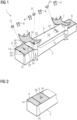
- Fig. 1 shows a production system 1.
- the production system 1 includes a mold 2 having a mold surface 3.
- the mold 2 - of which only one mold half is shown in Fig. 1 - is configured for manufacturing a composite fiber component, in the case of the example, a wind turbine blade.
- plies 4 - 7 of fiber material are picked up by workers from a storage or cutting station (not shown) and laid on the mold surface 3 or on a ply that has previously been placed on the mold surface 3.
- the fiber material may comprise, e.g., carbon fibers or glass fibers.
- balsa wood, foam or other materials may be placed on the mold surface 3 or on existing plies.
- the mold 2 is closed and a vacuum is created inside.
- the plies 4 - 7 inside the mold 2 are infused with a resin and cured.
- the cured blade can then be removed from the mold 2.
- the plies 4 - 7 must be placed in the right locations inside the mold 2. These locations are defined by a CAD (Computer Aided Design) model, for example.
- the CAD model contains 3D-coordinate data defining the layout of the plies and other materials.
- the CAD model is e.g. generated during the design phase of the blade. Therein, the plies and other materials have been arranged to obtain the desired blade properties, e.g. strength or weight.
- the production system 1 is designed to guide the workers (or robots in other embodiments) when placing the plies 4 - 7 and also to give feedback to them.
- the production system 1 comprises an optical device 8 ( Fig. 3 ) having multiple cameras 9 ( Fig. 1 ).
- the cameras 9 capture, using CCD (charge coupled device) chips or the like, the volume 10 above and including the mold surface 3.
- the optical device 8 may include lidar sensors (not shown).
- the cameras 9 cover the entire mold 2 or volume 10.
- the cameras 9 will record the plies 4 - 7, the free mold portion 11 as well as a pair of scissors 12 lying on the mold surface 2.
- the cameras 9 capture features such as reference points 13 of the mold 2 as well as edges 14 of respective plies 4 - 7.
- the production system 1 comprises a computing device 15 shown in Fig. 3 .
- the IoT devices 16 include the optical device 8 as well as a combined feedback and projector device 17.
- Both, the computing device 15 and the IoT devices 16, are located on the factory site 18 for minimal latency which will be explained in more detail.
- the computing device 15 is further in data communication with a data storage device 19 in the cloud 20.
- the computing device 15 uses machine learning, i.e. algorithms that improve automatically through experience (for example using deep learning and/or neural networks developed by labelling data sets), to analyze the data recorded by the cameras 9 in Fig. 1 .
- machine learning i.e. algorithms that improve automatically through experience (for example using deep learning and/or neural networks developed by labelling data sets)
- the features in particular, the scissors 12, the reference points 13 and edges 14
- 3D-coordinates also termed "determined parameter” herein.
- target coordinates also termed “reference parameter” herein
- the computing device 15 then yields a comparative result.
- the productions system 1 of Fig. 3 further comprises an onsite control device 23 which, depending on the comparative result, gives instructions to the feedback and projector device 17.
- the feedback and projector device 17 comprises a number of lasers 21 as shown in Fig. 1 .
- the lasers 21, controlled by the control device 23 projects visible markings 22 onto the ply 4 which has already been placed and onto the mold surface 2 indicating where the edges 14 of the ply 5 (also termed "k th pile” herein) should be arranged when the ply 5 is laid into the mold 2.
- the control device 23 will control the lasers 21 to generate a green triangle 24 as shown in Fig. 2 (or any other useful pattern) on the correctly placed ply 5. This gives the workers immediate feedback that the job is complete and that they can start with the next ply, for example.
- the lasers 21 will then proceed to generate markings 22 that will indicate the correct position of the next ply.
- the lasers 21 will show a red cross on ply 5. Also, the control device 23 will control the lasers 21 not to show the markings 14 for the next ply to be placed until the position of the ply 5 has been corrected.
- the control device 23 will control the lasers 21 to show the edge markings 22' for this ply.
- This function is obtained through the control device 23 controlling the cameras 9 to continuously capture all features of the entire mold surface 2 as well as of all plies 4 - 7 (also termed plies "1 st to k st " herein) and other materials on the mold surface 2 that have been placed until then.
- the computing device 15 uses edge computing the guidance or feedback to the user can be given in real time. Latency from the point in time when, for example, the position of a ply 4 - 7 changes until the guidance or feedback is produced by the lasers 21 is less than 2 or 3 seconds.
- the computing device 15 will also recognize any foreign objects such as the scissors 12 in Fig. 1 that have accidently been left on the mold surface 2.
- the control device 23 will then control the lasers 21 to, for example, circle the foreign object with a red line of light (illustrated in Fig. 1 with a circle around the scissors 12). This will avoid any foreign objects to become integrated into the finished blade, removal of which being expensive and detrimental to structural integrity of the blade.
- the computing device 15 may be configured to spot defects as they occur in the plies 4 - 7 and other materials used to build the blade on the mold 2. When such a defect is spotted, the control device 23 will control the lasers 21 to circle or otherwise highlight the defect.
- the production system 1 is capable of spotting new 'anomalies' for categorization as accepted or not, thereby allowing for continuous learning.
- the production system 1 registers something for the first time that looks abnormal, this is flagged to the production staff and forwarded to the quality department who can then allow this to be passed as acceptable or teach the system 1 that this should from now on be flagged as an error to be fixed.
- Fig. 1 there is a second team of workers laying the ply 7 simultaneous with the workers of the first team laying the ply 5.
- markings are also generated for the ply 7 (also termed "j th pile” herein) to guide the lay-up process.
- two or more teams can work in parallel in the production system 1 to build the blade in shorter time.
- the captured features are stored in the data storage device 19 (see Fig. 3 ).
- the computing device 15 may also be configured to recognize the material of which the blade is made of.
- a digital twin of the blade produced may be generated and saved. This data can be accessed when, for example during the lifetime of the blade (e.g. in operation), problems occur and knowledge of the exact position of plies and other materials is needed.
- Fig. 4 illustrates an embodiment of a method for producing composite fiber components, in particular wind turbine blades.
- step S1 features of the mold surface 3 (see Fig. 1 ) and of plies 4 - 7 laid on the mold surface 3 are optically captured.
- step S3 feedback 24 (or guidance such as the markings 14 in Fig. 1 ) is given to the workers depending on the comparative result in real time.
Landscapes
- Engineering & Computer Science (AREA)
- Mechanical Engineering (AREA)
- Chemical & Material Sciences (AREA)
- Composite Materials (AREA)
- Physics & Mathematics (AREA)
- General Physics & Mathematics (AREA)
- Moulding By Coating Moulds (AREA)
- Turbine Rotor Nozzle Sealing (AREA)
- Wind Motors (AREA)
- Hardware Redundancy (AREA)
Claims (13)
- Herstellungssystem (1) zur Herstellung eines Verbundfaserbauteils, insbesondere eines Windturbinenblattes, umfassend:eine Arbeitsfläche (3);eine optische Vorrichtung (8) zum optischen Erfassen von Merkmalen (12, 13, 14) der Arbeitsfläche (3) und/oder von auf der Arbeitsfläche (3) ausgelegten Lagen (4 - 7), wobei die Lagen (4 - 7) Fasermaterial umfassen;eine Rechenvorrichtung (15) zum Bestimmen eines Parameters der erfassten Merkmale (12, 13, 14) und eines Vergleichsergebnisses in Abhängigkeit von einem Vergleich des bestimmten Parameters und eines Referenzparameters;eine Rückmeldevorrichtung (17), die so konfiguriert ist, dass sie in Abhängigkeit von dem Vergleichsergebnis Rückmeldung (24) gibt;eine Projektionsvorrichtung (17) zum Projizieren eines Lichtmusters (22) auf die Arbeitsfläche (3) und/oder auf eine nach oben freiliegende Oberfläche einer Lage (4-7), um die Platzierung von Lagen (4-7) auf der Arbeitsfläche (3) und/oder auf der Lage (4-7) zu leiten; undeine Steuervorrichtung (23), dadurch gekennzeichnet, dass die Steuervorrichtung konfiguriert ist zum Steuern:der Projektionsvorrichtung (17) zum Projizieren eines k-ten Musters (22) entsprechend einer Zielposition einer k-ten Lage (5) und gleichzeitig zum Projizieren eines j-ten Musters entsprechend einer Zielposition einer j-ten Lage (7);der optischen Vorrichtung (8) zum optischen Erfassen von Merkmalen (12, 13, 14) der k-ten und j-ten Lage (4 - 7), die auf der Arbeitsfläche (3) ausgelegt sind;der Rechenvorrichtung (15) zum Bestimmen einer Position der erfassten Merkmale (14) und eines Vergleichsergebnisses in Abhängigkeit von einem Vergleich der bestimmten Position und einer Referenzposition für die k-te bzw. j-te Lage (5, 7); undder Rückmeldevorrichtung (17), um in Abhängigkeit von dem jeweiligen Vergleichsergebnis Rückmeldung zu geben;wobei k von 1 bis N inkrementiert wird, wobei N die Gesamtzahl an Lagen (4, 5) bezeichnet, die einen ersten Abschnitt des herzustellenden Verbundbauteils bilden, und j von 1 bis M inkrementiert wird, wobei M die Gesamtzahl an Lagen (6, 7) bezeichnet, die einen zweiten Abschnitt des herzustellenden Verbundbauteils bilden.
- System nach Anspruch 1,
wobei die optische Vorrichtung (8) eine Vielzahl optischer Kameras (9) und/oder Lidar-Sensoren umfasst. - System nach Anspruch 1 oder 2,mit einer Form (2), wobei es sich bei der Arbeitsfläche (3) um eine Formfläche handelt, und/oderwobei die optische Vorrichtung (8) Merkmale innerhalb eines Volumens über und/oder einschließlich der Formoberfläche (3) erfasst.
- System nach einem der Ansprüche 1 bis 3,wobei die erfassten Merkmale (12, 13, 14) Kanten, Material und/oder Defekte der Lagen (4 - 7), Referenzpunkte auf der Arbeitsfläche (3) und/oder Fremdkörper umfassen, und/oderwobei der Parameter eine Position, Geometrie, Farbe und/oder Textur umfasst.
- System nach einem der Ansprüche 1 bis 4,
wobei die Rückmeldung (24) eine visuelle und/oder akustische Rückmeldung umfasst. - System nach Anspruch 5,
wobei die visuelle Rückmeldung (24) ein Lichtmuster umfasst, das auf die Arbeitsfläche (3) und/oder auf eine nach oben freiliegende Oberfläche einer Lage (4 - 7) projiziert wird. - System nach einem der Ansprüche 1 bis 6,
wobei die Rückmelde- und/oder die Projektionsvorrichtung (17) einen oder mehrere Laser (21) umfasst. - System nach einem der Ansprüche 1 bis 7,
wobei das Muster (22) eine Zielposition einer auf der Arbeitsfläche (3) und/oder auf der nach oben freiliegenden Lage (4-7) zu platzierenden Lage (4-7) abgrenzt, wobei das Muster (22) bevorzugt eine Zielposition von Kanten (14) der Lage abgrenzt. - System nach einem der Ansprüche 1 bis 8,
wobei die Steuervorrichtung (23) konfiguriert ist zum Steuern:der Projektionsvorrichtung (17) zum Projizieren eines ersten Musters (22') entsprechend einer Zielposition einer ersten Lage (4) und eines zweiten Musters (22) entsprechend einer Zielposition einer zweiten Lage (5);der optischen Vorrichtung (8) zum optischen Erfassen von Merkmalen (14') der ersten Lage (4), die auf der Arbeitsfläche (3) ausgelegt ist; undder Rechenvorrichtung (15) zum Bestimmen einer Position der erfassten Merkmale (14') der ersten Lage und eines Vergleichsergebnisses in Abhängigkeit von einem Vergleich der bestimmten Position und einer Referenzposition;wobei die Projektion des zweiten Musters (22) von dem Vergleichsergebnis abhängt. - System nach einem der Ansprüche 1 bis 9,
wobei die Steuervorrichtung (23) konfiguriert ist zum Steuern:der Projektionsvorrichtung (17) zum Projizieren eines k-ten Musters (22) entsprechend einer Zielposition einer k-ten Lage (5); undder optischen Vorrichtung (8) zum Erfassen der Merkmale (12, 13, 14) der Arbeitsfläche (3) und/oder der ersten bis k-ten Lage (4, 5), die auf der Arbeitsfläche (3) ausgelegt ist;wobei k von 1 bis N inkrementiert wird, wobei N die Gesamtzahl an Lagen (4, 5) bezeichnet, aus denen das herzustellende Verbundfaserbauteil oder ein Teil davon gebildet wird. - System nach einem der Ansprüche 1 bis 10,
ferner umfassend eine Speichervorrichtung (19) zum Speichern der erfassten Merkmale (12, 13, 14) und/oder wobei die Rechenvorrichtung (15) einen Maschinenlernalgorithmus verwendet und/oder Edge Computing verwendet. - Verfahren zum Herstellen eines Verbundfaserbauteils, insbesondere eines Windturbinenblattes, umfassend die Schritte:optisches Erfassen (S1) von Merkmalen (12, 13, 14) einer Arbeitsfläche (3) und/oder von auf der Arbeitsfläche (3) ausgelegten Lagen (4 - 7), wobei die Lagen (4 - 7) Fasermaterial umfassen;Bestimmen (S2) eines Parameters der erfassten Merkmale (12, 13, 14) und eines Vergleichsergebnisses in Abhängigkeit von einem Vergleich des bestimmten Parameters und eines Referenzparameters;dadurch gekennzeichnet, dass das Verfahren ferner umfasst:Projizieren eines k-ten Musters (22) entsprechend einer Zielposition einer k-ten Lage (5), und gleichzeitig Projizieren eines j-ten Musters entsprechend einer Zielposition einer j-ten Lage (7);Erfassen von Merkmalen (12, 13, 14) der k-ten und j-ten Lage (4 - 7), die auf der Arbeitsfläche (3) ausgelegt sind;Bestimmen einer Position der erfassten Merkmale (14) und eines Vergleichsergebnisses in Abhängigkeit von einem Vergleich der bestimmten Position und einer Referenzposition für die k-te bzw. j-te Lage (5, 7); undGeben einer Rückmeldung in Abhängigkeit von dem jeweiligen Vergleichsergebnis;Erhöhen von k von 1 bis N, wobei N die Gesamtzahl an Lagen (4, 5) bezeichnet, die einen ersten Abschnitt des herzustellenden Verbundbauteils bilden, und Erhöhen von j von 1 bis M, wobei M die Gesamtzahl an Lagen (6, 7) bezeichnet, die einen zweiten Abschnitt des herzustellenden Verbundbauteils bilden.
- Computerprogrammprodukt, das einen Programmcode umfasst, um bei Ausführung auf einem Herstellungssystem nach einem der Ansprüche 1 bis 11 das Verfahren nach Anspruch 12 auszuführen.
Applications Claiming Priority (2)
| Application Number | Priority Date | Filing Date | Title |
|---|---|---|---|
| EP21382093.9A EP4039455A1 (de) | 2021-02-04 | 2021-02-04 | Produktionssystem, verfahren und computerprogrammprodukt |
| PCT/EP2022/052596 WO2022167531A1 (en) | 2021-02-04 | 2022-02-03 | Production system, method and computer program product |
Publications (2)
| Publication Number | Publication Date |
|---|---|
| EP4263189A1 EP4263189A1 (de) | 2023-10-25 |
| EP4263189B1 true EP4263189B1 (de) | 2024-09-11 |
Family
ID=74732826
Family Applications (2)
| Application Number | Title | Priority Date | Filing Date |
|---|---|---|---|
| EP21382093.9A Ceased EP4039455A1 (de) | 2021-02-04 | 2021-02-04 | Produktionssystem, verfahren und computerprogrammprodukt |
| EP22703635.7A Active EP4263189B1 (de) | 2021-02-04 | 2022-02-03 | Produktionssystem, verfahren und computerprogrammprodukt |
Family Applications Before (1)
| Application Number | Title | Priority Date | Filing Date |
|---|---|---|---|
| EP21382093.9A Ceased EP4039455A1 (de) | 2021-02-04 | 2021-02-04 | Produktionssystem, verfahren und computerprogrammprodukt |
Country Status (10)
| Country | Link |
|---|---|
| US (1) | US20240109264A1 (de) |
| EP (2) | EP4039455A1 (de) |
| CN (1) | CN116829339A (de) |
| CA (1) | CA3210548A1 (de) |
| DK (1) | DK4263189T3 (de) |
| ES (1) | ES2999073T3 (de) |
| PL (1) | PL4263189T3 (de) |
| PT (1) | PT4263189T (de) |
| TW (1) | TWI820595B (de) |
| WO (1) | WO2022167531A1 (de) |
Families Citing this family (4)
| Publication number | Priority date | Publication date | Assignee | Title |
|---|---|---|---|---|
| EP4331818A1 (de) * | 2022-09-01 | 2024-03-06 | Siemens Gamesa Renewable Energy A/S | Laserprojektoranordnung |
| CN120936484A (zh) * | 2023-03-23 | 2025-11-11 | 维斯塔斯风力系统集团公司 | 使用智能成像的风力涡轮机叶片制造 |
| WO2025067619A1 (en) * | 2023-09-29 | 2025-04-03 | Vestas Wind Systems A/S | A method of making a wind turbine blade component |
| US20250319672A1 (en) * | 2024-04-11 | 2025-10-16 | Northrop Grumman Systems Corporation | Methods of forming a composite structure and associated automated manufacturing systems and components |
Family Cites Families (8)
| Publication number | Priority date | Publication date | Assignee | Title |
|---|---|---|---|---|
| FR2665664B1 (fr) * | 1990-08-08 | 1994-04-08 | Aerospatiale Ste Nationale Indle | Appareillage d'aide au drapage manuel de pieces en materiaux composites. |
| US6064429A (en) * | 1997-08-18 | 2000-05-16 | Mcdonnell Douglas Corporation | Foreign object video detection and alert system and method |
| US6843565B2 (en) * | 2002-08-02 | 2005-01-18 | General Electric Company | Laser projection system to facilitate layup of complex composite shapes |
| US7236625B2 (en) * | 2003-07-28 | 2007-06-26 | The Boeing Company | Systems and method for identifying foreign objects and debris (FOD) and defects during fabrication of a composite structure |
| WO2011047167A1 (en) * | 2009-10-16 | 2011-04-21 | Gerber Scientific International, Inc. | Methods and systems for manufacturing composite parts |
| EP3645255B1 (de) * | 2017-06-30 | 2023-08-23 | TPI Composites, Inc. | Optimierung eines aufschichtverfahrens zur herstellung von windturbinenschaufeln unter verwendung eines optischen projektionssystems auf modellbasis |
| CN111954758B (zh) * | 2017-12-29 | 2024-03-12 | 泰普爱复合材料股份有限公司 | 使用激光投影系统制造风力涡轮机叶片的半自动铺层过程 |
| US12109764B2 (en) * | 2018-04-11 | 2024-10-08 | Textron Innovations Inc. | Automated placement of composite material |
-
2021
- 2021-02-04 EP EP21382093.9A patent/EP4039455A1/de not_active Ceased
-
2022
- 2022-01-28 TW TW111103943A patent/TWI820595B/zh active
- 2022-02-03 PL PL22703635.7T patent/PL4263189T3/pl unknown
- 2022-02-03 WO PCT/EP2022/052596 patent/WO2022167531A1/en not_active Ceased
- 2022-02-03 EP EP22703635.7A patent/EP4263189B1/de active Active
- 2022-02-03 CA CA3210548A patent/CA3210548A1/en active Pending
- 2022-02-03 ES ES22703635T patent/ES2999073T3/es active Active
- 2022-02-03 DK DK22703635.7T patent/DK4263189T3/da active
- 2022-02-03 US US18/274,684 patent/US20240109264A1/en active Pending
- 2022-02-03 CN CN202280013498.8A patent/CN116829339A/zh active Pending
- 2022-02-03 PT PT227036357T patent/PT4263189T/pt unknown
Also Published As
| Publication number | Publication date |
|---|---|
| ES2999073T3 (en) | 2025-02-24 |
| WO2022167531A1 (en) | 2022-08-11 |
| CA3210548A1 (en) | 2022-08-11 |
| EP4263189A1 (de) | 2023-10-25 |
| TW202302325A (zh) | 2023-01-16 |
| CN116829339A (zh) | 2023-09-29 |
| EP4039455A1 (de) | 2022-08-10 |
| PL4263189T3 (pl) | 2024-11-25 |
| DK4263189T3 (da) | 2024-10-28 |
| US20240109264A1 (en) | 2024-04-04 |
| TWI820595B (zh) | 2023-11-01 |
| PT4263189T (pt) | 2024-11-19 |
Similar Documents
| Publication | Publication Date | Title |
|---|---|---|
| EP4263189B1 (de) | Produktionssystem, verfahren und computerprogrammprodukt | |
| CN104583541B (zh) | 切割用于制造涡轮机零件的预成形件的方法和系统 | |
| CN104915635B (zh) | 检查复合物品的方法和计算机系统、计算机可读介质 | |
| EP4134910A1 (de) | Verfahren zur prozessbegleitenden detektion und abbildung von fehlern in einer verbundschicht | |
| US12517501B2 (en) | Ply templating for composite fabrication with AI quality control modules | |
| US20220009164A1 (en) | Post-processing 3D Printing Components | |
| US10262404B2 (en) | Method and system for articulation of a visual inspection device | |
| US20220134691A1 (en) | Systems and Methods for Actualizing Simulated Scarfs and Patches for Repair of Composite Laminates | |
| US12293511B2 (en) | Anomaly detection system in the automatic placement of composites during the manufacturing of structural elements | |
| CN119368985B (zh) | 一种用于标识牌的焊接控制方法及装置 | |
| CN112580935A (zh) | 一种基于机器视觉的工业产品生产流程溯源分析方法 | |
| US11501030B2 (en) | Computer-implemented method and apparatus for automatically generating identified image data and analysis apparatus for checking a component | |
| CN111435400A (zh) | 一种零件的修复方法、修复装置及3d打印机 | |
| KR101405039B1 (ko) | 사용자 맞춤형 가공공정 자동화 시스템 및 방법 | |
| JP2021100796A (ja) | 射出成形システム | |
| CN118587744A (zh) | 一种鸡肉屠宰分割骨头去除多模态视觉识别方法 | |
| Masters et al. | Defect-free Ceramic Hybrid-AM using Intelligent Layer Reworking | |
| CN118991029B (zh) | 一种车标的3d立体打印装置 | |
| CN120886493A (zh) | 叶片加工方法、电子设备及管理系统 | |
| CN120936484A (zh) | 使用智能成像的风力涡轮机叶片制造 | |
| WO2023064400A1 (en) | Systems and methods for composite fabrication with ai quality control modules | |
| WO2024258779A1 (en) | Engine inspection systems and methods | |
| EP3395553B1 (de) | Messung von lagengrenzen | |
| WO2025176683A1 (en) | Monitoring of composite part manufacture | |
| CN120010390A (zh) | 一种石墨包边增强的模具控制方法及系统 |
Legal Events
| Date | Code | Title | Description |
|---|---|---|---|
| STAA | Information on the status of an ep patent application or granted ep patent |
Free format text: STATUS: UNKNOWN |
|
| STAA | Information on the status of an ep patent application or granted ep patent |
Free format text: STATUS: THE INTERNATIONAL PUBLICATION HAS BEEN MADE |
|
| PUAI | Public reference made under article 153(3) epc to a published international application that has entered the european phase |
Free format text: ORIGINAL CODE: 0009012 |
|
| STAA | Information on the status of an ep patent application or granted ep patent |
Free format text: STATUS: REQUEST FOR EXAMINATION WAS MADE |
|
| 17P | Request for examination filed |
Effective date: 20230717 |
|
| AK | Designated contracting states |
Kind code of ref document: A1 Designated state(s): AL AT BE BG CH CY CZ DE DK EE ES FI FR GB GR HR HU IE IS IT LI LT LU LV MC MK MT NL NO PL PT RO RS SE SI SK SM TR |
|
| GRAP | Despatch of communication of intention to grant a patent |
Free format text: ORIGINAL CODE: EPIDOSNIGR1 |
|
| STAA | Information on the status of an ep patent application or granted ep patent |
Free format text: STATUS: GRANT OF PATENT IS INTENDED |
|
| DAV | Request for validation of the european patent (deleted) | ||
| DAX | Request for extension of the european patent (deleted) | ||
| INTG | Intention to grant announced |
Effective date: 20240422 |
|
| GRAS | Grant fee paid |
Free format text: ORIGINAL CODE: EPIDOSNIGR3 |
|
| GRAA | (expected) grant |
Free format text: ORIGINAL CODE: 0009210 |
|
| STAA | Information on the status of an ep patent application or granted ep patent |
Free format text: STATUS: THE PATENT HAS BEEN GRANTED |
|
| AK | Designated contracting states |
Kind code of ref document: B1 Designated state(s): AL AT BE BG CH CY CZ DE DK EE ES FI FR GB GR HR HU IE IS IT LI LT LU LV MC MK MT NL NO PL PT RO RS SE SI SK SM TR |
|
| REG | Reference to a national code |
Ref country code: GB Ref legal event code: FG4D |
|
| REG | Reference to a national code |
Ref country code: CH Ref legal event code: EP |
|
| REG | Reference to a national code |
Ref country code: DE Ref legal event code: R096 Ref document number: 602022006065 Country of ref document: DE |
|
| REG | Reference to a national code |
Ref country code: IE Ref legal event code: FG4D |
|
| REG | Reference to a national code |
Ref country code: NL Ref legal event code: FP |
|
| REG | Reference to a national code |
Ref country code: DK Ref legal event code: T3 Effective date: 20241024 |
|
| REG | Reference to a national code |
Ref country code: PT Ref legal event code: SC4A Ref document number: 4263189 Country of ref document: PT Date of ref document: 20241119 Kind code of ref document: T Free format text: AVAILABILITY OF NATIONAL TRANSLATION Effective date: 20241113 |
|
| REG | Reference to a national code |
Ref country code: SE Ref legal event code: TRGR |
|
| REG | Reference to a national code |
Ref country code: LT Ref legal event code: MG9D |
|
| PG25 | Lapsed in a contracting state [announced via postgrant information from national office to epo] |
Ref country code: NO Free format text: LAPSE BECAUSE OF FAILURE TO SUBMIT A TRANSLATION OF THE DESCRIPTION OR TO PAY THE FEE WITHIN THE PRESCRIBED TIME-LIMIT Effective date: 20241211 |
|
| PG25 | Lapsed in a contracting state [announced via postgrant information from national office to epo] |
Ref country code: GR Free format text: LAPSE BECAUSE OF FAILURE TO SUBMIT A TRANSLATION OF THE DESCRIPTION OR TO PAY THE FEE WITHIN THE PRESCRIBED TIME-LIMIT Effective date: 20241212 Ref country code: FI Free format text: LAPSE BECAUSE OF FAILURE TO SUBMIT A TRANSLATION OF THE DESCRIPTION OR TO PAY THE FEE WITHIN THE PRESCRIBED TIME-LIMIT Effective date: 20240911 |
|
| PG25 | Lapsed in a contracting state [announced via postgrant information from national office to epo] |
Ref country code: BG Free format text: LAPSE BECAUSE OF FAILURE TO SUBMIT A TRANSLATION OF THE DESCRIPTION OR TO PAY THE FEE WITHIN THE PRESCRIBED TIME-LIMIT Effective date: 20240911 |
|
| PG25 | Lapsed in a contracting state [announced via postgrant information from national office to epo] |
Ref country code: LV Free format text: LAPSE BECAUSE OF FAILURE TO SUBMIT A TRANSLATION OF THE DESCRIPTION OR TO PAY THE FEE WITHIN THE PRESCRIBED TIME-LIMIT Effective date: 20240911 |
|
| PG25 | Lapsed in a contracting state [announced via postgrant information from national office to epo] |
Ref country code: HR Free format text: LAPSE BECAUSE OF FAILURE TO SUBMIT A TRANSLATION OF THE DESCRIPTION OR TO PAY THE FEE WITHIN THE PRESCRIBED TIME-LIMIT Effective date: 20240911 |
|
| PG25 | Lapsed in a contracting state [announced via postgrant information from national office to epo] |
Ref country code: RS Free format text: LAPSE BECAUSE OF FAILURE TO SUBMIT A TRANSLATION OF THE DESCRIPTION OR TO PAY THE FEE WITHIN THE PRESCRIBED TIME-LIMIT Effective date: 20241211 |
|
| PG25 | Lapsed in a contracting state [announced via postgrant information from national office to epo] |
Ref country code: RS Free format text: LAPSE BECAUSE OF FAILURE TO SUBMIT A TRANSLATION OF THE DESCRIPTION OR TO PAY THE FEE WITHIN THE PRESCRIBED TIME-LIMIT Effective date: 20241211 Ref country code: NO Free format text: LAPSE BECAUSE OF FAILURE TO SUBMIT A TRANSLATION OF THE DESCRIPTION OR TO PAY THE FEE WITHIN THE PRESCRIBED TIME-LIMIT Effective date: 20241211 Ref country code: LV Free format text: LAPSE BECAUSE OF FAILURE TO SUBMIT A TRANSLATION OF THE DESCRIPTION OR TO PAY THE FEE WITHIN THE PRESCRIBED TIME-LIMIT Effective date: 20240911 Ref country code: HR Free format text: LAPSE BECAUSE OF FAILURE TO SUBMIT A TRANSLATION OF THE DESCRIPTION OR TO PAY THE FEE WITHIN THE PRESCRIBED TIME-LIMIT Effective date: 20240911 Ref country code: GR Free format text: LAPSE BECAUSE OF FAILURE TO SUBMIT A TRANSLATION OF THE DESCRIPTION OR TO PAY THE FEE WITHIN THE PRESCRIBED TIME-LIMIT Effective date: 20241212 Ref country code: FI Free format text: LAPSE BECAUSE OF FAILURE TO SUBMIT A TRANSLATION OF THE DESCRIPTION OR TO PAY THE FEE WITHIN THE PRESCRIBED TIME-LIMIT Effective date: 20240911 Ref country code: BG Free format text: LAPSE BECAUSE OF FAILURE TO SUBMIT A TRANSLATION OF THE DESCRIPTION OR TO PAY THE FEE WITHIN THE PRESCRIBED TIME-LIMIT Effective date: 20240911 |
|
| REG | Reference to a national code |
Ref country code: AT Ref legal event code: MK05 Ref document number: 1722344 Country of ref document: AT Kind code of ref document: T Effective date: 20240911 |
|
| REG | Reference to a national code |
Ref country code: ES Ref legal event code: FG2A Ref document number: 2999073 Country of ref document: ES Kind code of ref document: T3 Effective date: 20250224 |
|
| PGFP | Annual fee paid to national office [announced via postgrant information from national office to epo] |
Ref country code: NL Payment date: 20250224 Year of fee payment: 4 |
|
| PG25 | Lapsed in a contracting state [announced via postgrant information from national office to epo] |
Ref country code: IS Free format text: LAPSE BECAUSE OF FAILURE TO SUBMIT A TRANSLATION OF THE DESCRIPTION OR TO PAY THE FEE WITHIN THE PRESCRIBED TIME-LIMIT Effective date: 20250111 |
|
| PGFP | Annual fee paid to national office [announced via postgrant information from national office to epo] |
Ref country code: PT Payment date: 20250113 Year of fee payment: 4 Ref country code: DE Payment date: 20250226 Year of fee payment: 4 |
|
| PG25 | Lapsed in a contracting state [announced via postgrant information from national office to epo] |
Ref country code: SM Free format text: LAPSE BECAUSE OF FAILURE TO SUBMIT A TRANSLATION OF THE DESCRIPTION OR TO PAY THE FEE WITHIN THE PRESCRIBED TIME-LIMIT Effective date: 20240911 Ref country code: RO Free format text: LAPSE BECAUSE OF FAILURE TO SUBMIT A TRANSLATION OF THE DESCRIPTION OR TO PAY THE FEE WITHIN THE PRESCRIBED TIME-LIMIT Effective date: 20240911 |
|
| PGFP | Annual fee paid to national office [announced via postgrant information from national office to epo] |
Ref country code: DK Payment date: 20250224 Year of fee payment: 4 |
|
| PGFP | Annual fee paid to national office [announced via postgrant information from national office to epo] |
Ref country code: ES Payment date: 20250317 Year of fee payment: 4 |
|
| PGFP | Annual fee paid to national office [announced via postgrant information from national office to epo] |
Ref country code: SE Payment date: 20250224 Year of fee payment: 4 Ref country code: IE Payment date: 20250217 Year of fee payment: 4 |
|
| PG25 | Lapsed in a contracting state [announced via postgrant information from national office to epo] |
Ref country code: EE Free format text: LAPSE BECAUSE OF FAILURE TO SUBMIT A TRANSLATION OF THE DESCRIPTION OR TO PAY THE FEE WITHIN THE PRESCRIBED TIME-LIMIT Effective date: 20240911 Ref country code: AT Free format text: LAPSE BECAUSE OF FAILURE TO SUBMIT A TRANSLATION OF THE DESCRIPTION OR TO PAY THE FEE WITHIN THE PRESCRIBED TIME-LIMIT Effective date: 20240911 |
|
| PG25 | Lapsed in a contracting state [announced via postgrant information from national office to epo] |
Ref country code: CZ Free format text: LAPSE BECAUSE OF FAILURE TO SUBMIT A TRANSLATION OF THE DESCRIPTION OR TO PAY THE FEE WITHIN THE PRESCRIBED TIME-LIMIT Effective date: 20240911 |
|
| PGFP | Annual fee paid to national office [announced via postgrant information from national office to epo] |
Ref country code: FR Payment date: 20250224 Year of fee payment: 4 Ref country code: PL Payment date: 20250108 Year of fee payment: 4 |
|
| PG25 | Lapsed in a contracting state [announced via postgrant information from national office to epo] |
Ref country code: SK Free format text: LAPSE BECAUSE OF FAILURE TO SUBMIT A TRANSLATION OF THE DESCRIPTION OR TO PAY THE FEE WITHIN THE PRESCRIBED TIME-LIMIT Effective date: 20240911 |
|
| PGFP | Annual fee paid to national office [announced via postgrant information from national office to epo] |
Ref country code: IT Payment date: 20250228 Year of fee payment: 4 |
|
| REG | Reference to a national code |
Ref country code: DE Ref legal event code: R097 Ref document number: 602022006065 Country of ref document: DE |
|
| PLBE | No opposition filed within time limit |
Free format text: ORIGINAL CODE: 0009261 |
|
| STAA | Information on the status of an ep patent application or granted ep patent |
Free format text: STATUS: NO OPPOSITION FILED WITHIN TIME LIMIT |
|
| 26N | No opposition filed |
Effective date: 20250612 |
|
| PG25 | Lapsed in a contracting state [announced via postgrant information from national office to epo] |
Ref country code: MC Free format text: LAPSE BECAUSE OF FAILURE TO SUBMIT A TRANSLATION OF THE DESCRIPTION OR TO PAY THE FEE WITHIN THE PRESCRIBED TIME-LIMIT Effective date: 20240911 |
|
| REG | Reference to a national code |
Ref country code: CH Ref legal event code: PL |
|
| PG25 | Lapsed in a contracting state [announced via postgrant information from national office to epo] |
Ref country code: LU Free format text: LAPSE BECAUSE OF NON-PAYMENT OF DUE FEES Effective date: 20250203 |
|
| PG25 | Lapsed in a contracting state [announced via postgrant information from national office to epo] |
Ref country code: CH Free format text: LAPSE BECAUSE OF NON-PAYMENT OF DUE FEES Effective date: 20250228 |
|
| REG | Reference to a national code |
Ref country code: BE Ref legal event code: MM Effective date: 20250228 |
|
| PG25 | Lapsed in a contracting state [announced via postgrant information from national office to epo] |
Ref country code: BE Free format text: LAPSE BECAUSE OF NON-PAYMENT OF DUE FEES Effective date: 20250228 |