EP4262611B1 - Medical implant port assemblies and related methods - Google Patents
Medical implant port assemblies and related methods Download PDFInfo
- Publication number
- EP4262611B1 EP4262611B1 EP22700195.5A EP22700195A EP4262611B1 EP 4262611 B1 EP4262611 B1 EP 4262611B1 EP 22700195 A EP22700195 A EP 22700195A EP 4262611 B1 EP4262611 B1 EP 4262611B1
- Authority
- EP
- European Patent Office
- Prior art keywords
- port
- tissue expander
- coil
- housing
- cover
- Prior art date
- Legal status (The legal status is an assumption and is not a legal conclusion. Google has not performed a legal analysis and makes no representation as to the accuracy of the status listed.)
- Active
Links
Images




Classifications
-
- A—HUMAN NECESSITIES
- A61—MEDICAL OR VETERINARY SCIENCE; HYGIENE
- A61B—DIAGNOSIS; SURGERY; IDENTIFICATION
- A61B5/00—Measuring for diagnostic purposes; Identification of persons
- A61B5/06—Devices, other than using radiation, for detecting or locating foreign bodies ; Determining position of diagnostic devices within or on the body of the patient
- A61B5/061—Determining position of a probe within the body employing means separate from the probe, e.g. sensing internal probe position employing impedance electrodes on the surface of the body
-
- A—HUMAN NECESSITIES
- A61—MEDICAL OR VETERINARY SCIENCE; HYGIENE
- A61B—DIAGNOSIS; SURGERY; IDENTIFICATION
- A61B90/00—Instruments, implements or accessories specially adapted for surgery or diagnosis and not covered by any of the groups A61B1/00 - A61B50/00, e.g. for luxation treatment or for protecting wound edges
- A61B90/02—Devices for expanding tissue, e.g. skin tissue
-
- A—HUMAN NECESSITIES
- A61—MEDICAL OR VETERINARY SCIENCE; HYGIENE
- A61B—DIAGNOSIS; SURGERY; IDENTIFICATION
- A61B90/00—Instruments, implements or accessories specially adapted for surgery or diagnosis and not covered by any of the groups A61B1/00 - A61B50/00, e.g. for luxation treatment or for protecting wound edges
- A61B90/90—Identification means for patients or instruments, e.g. tags
- A61B90/98—Identification means for patients or instruments, e.g. tags using electromagnetic means, e.g. transponders
-
- A—HUMAN NECESSITIES
- A61—MEDICAL OR VETERINARY SCIENCE; HYGIENE
- A61M—DEVICES FOR INTRODUCING MEDIA INTO, OR ONTO, THE BODY; DEVICES FOR TRANSDUCING BODY MEDIA OR FOR TAKING MEDIA FROM THE BODY; DEVICES FOR PRODUCING OR ENDING SLEEP OR STUPOR
- A61M39/00—Tubes, tube connectors, tube couplings, valves, access sites or the like, specially adapted for medical use
- A61M39/02—Access sites
- A61M39/0208—Subcutaneous access sites for injecting or removing fluids
-
- A—HUMAN NECESSITIES
- A61—MEDICAL OR VETERINARY SCIENCE; HYGIENE
- A61M—DEVICES FOR INTRODUCING MEDIA INTO, OR ONTO, THE BODY; DEVICES FOR TRANSDUCING BODY MEDIA OR FOR TAKING MEDIA FROM THE BODY; DEVICES FOR PRODUCING OR ENDING SLEEP OR STUPOR
- A61M39/00—Tubes, tube connectors, tube couplings, valves, access sites or the like, specially adapted for medical use
- A61M39/02—Access sites
- A61M39/04—Access sites having pierceable self-sealing members
-
- A—HUMAN NECESSITIES
- A61—MEDICAL OR VETERINARY SCIENCE; HYGIENE
- A61F—FILTERS IMPLANTABLE INTO BLOOD VESSELS; PROSTHESES; DEVICES PROVIDING PATENCY TO, OR PREVENTING COLLAPSING OF, TUBULAR STRUCTURES OF THE BODY, e.g. STENTS; ORTHOPAEDIC, NURSING OR CONTRACEPTIVE DEVICES; FOMENTATION; TREATMENT OR PROTECTION OF EYES OR EARS; BANDAGES, DRESSINGS OR ABSORBENT PADS; FIRST-AID KITS
- A61F2/00—Filters implantable into blood vessels; Prostheses, i.e. artificial substitutes or replacements for parts of the body; Appliances for connecting them with the body; Devices providing patency to, or preventing collapsing of, tubular structures of the body, e.g. stents
- A61F2/0059—Cosmetic or alloplastic implants
-
- A—HUMAN NECESSITIES
- A61—MEDICAL OR VETERINARY SCIENCE; HYGIENE
- A61F—FILTERS IMPLANTABLE INTO BLOOD VESSELS; PROSTHESES; DEVICES PROVIDING PATENCY TO, OR PREVENTING COLLAPSING OF, TUBULAR STRUCTURES OF THE BODY, e.g. STENTS; ORTHOPAEDIC, NURSING OR CONTRACEPTIVE DEVICES; FOMENTATION; TREATMENT OR PROTECTION OF EYES OR EARS; BANDAGES, DRESSINGS OR ABSORBENT PADS; FIRST-AID KITS
- A61F2/00—Filters implantable into blood vessels; Prostheses, i.e. artificial substitutes or replacements for parts of the body; Appliances for connecting them with the body; Devices providing patency to, or preventing collapsing of, tubular structures of the body, e.g. stents
- A61F2/02—Prostheses implantable into the body
- A61F2/12—Mammary prostheses
-
- A—HUMAN NECESSITIES
- A61—MEDICAL OR VETERINARY SCIENCE; HYGIENE
- A61F—FILTERS IMPLANTABLE INTO BLOOD VESSELS; PROSTHESES; DEVICES PROVIDING PATENCY TO, OR PREVENTING COLLAPSING OF, TUBULAR STRUCTURES OF THE BODY, e.g. STENTS; ORTHOPAEDIC, NURSING OR CONTRACEPTIVE DEVICES; FOMENTATION; TREATMENT OR PROTECTION OF EYES OR EARS; BANDAGES, DRESSINGS OR ABSORBENT PADS; FIRST-AID KITS
- A61F2250/00—Special features of prostheses classified in groups A61F2/00 - A61F2/26 or A61F2/82 or A61F9/00 or A61F11/00 or subgroups thereof
- A61F2250/0058—Additional features; Implant or prostheses properties not otherwise provided for
- A61F2250/0096—Markers and sensors for detecting a position or changes of a position of an implant, e.g. RF sensors, ultrasound markers
-
- A—HUMAN NECESSITIES
- A61—MEDICAL OR VETERINARY SCIENCE; HYGIENE
- A61M—DEVICES FOR INTRODUCING MEDIA INTO, OR ONTO, THE BODY; DEVICES FOR TRANSDUCING BODY MEDIA OR FOR TAKING MEDIA FROM THE BODY; DEVICES FOR PRODUCING OR ENDING SLEEP OR STUPOR
- A61M39/00—Tubes, tube connectors, tube couplings, valves, access sites or the like, specially adapted for medical use
- A61M39/02—Access sites
- A61M39/0208—Subcutaneous access sites for injecting or removing fluids
- A61M2039/0238—Subcutaneous access sites for injecting or removing fluids having means for locating the implanted device to insure proper injection, e.g. radio-emitter, protuberances, radio-opaque markers
Definitions
- the present disclosure relates generally to medical implant components useful for determining the location and/or orientation of the medical implant inside a subject, e.g., a patient.
- the present disclosure includes port assemblies detectable with an external reader.
- the port assembly may be configured as an injection port for a medical implant including a tissue expander.
- Related methods of use of the port assemblies and medical implants are also described.
- Implantable medical devices may be implanted into patients for a variety of reasons, including, for example, to improve the clinical condition of a patient or to replace natural patient tissue.
- Injection ports of tissue expanders provide access to tissue expanders while implanted within a patient.
- Electromagnetic signals may be used to provide information on the location of an injection port of the tissue expander to facilitate access to the port.
- the injection port When a tissue expander is in an irregular position, such as when a tissue expander has flipped position, the injection port may be inaccessible to a physician or other medical professional, who could inadvertently puncture the tissue expander in an effort to access the injection port.
- EP 3 556 317 A1 discloses implantable transponders comprising no ferromagnetic parts for use in medical implants; methods for using such transponders, readers for detecting such transponders and methods for using such readers are also described.
- US 2019/0247138 A1 discloses a tissue expander comprising a shell defining a chamber, and having a flexible wall and a port disposed through the flexible wall.
- the present disclosure includes port assemblies useful for providing access to a medical implant and/or determining the location and/or orientation of the implant inside a patient.
- injection ports for tissue expanders comprising features that may provide for increased safety and/or decreased necessity for invasive procedures. While portions of this disclosure refer to tissue expanders and breast implants, the devices and methods disclosed herein may be used with other implantable medical devices, such as, e.g., other implants used in cosmetic and/or reconstruction procedures.
- the port assemblies herein may provide distinctive signature(s) via electronic signal(s) and/or image(s) to assist a medical professional to determine the location and orientation of a medical implant in a non-invasive manner.
- the port assemblies herein may provide for introduction and/or removal of a fluid from the implant (e.g., an injection port of a tissue expander) but are not limited to fluid injection capability.
- the claimed invention is defined by independent claims 1 and 14, and includes a tissue expander comprising an integrated port (also referred to herein as a port or port assembly), wherein the integrated port comprises a housing comprising a first portion coupled to a second portion, wherein the first portion and the second portion comprise different materials; and a self-sealing cover (e.g., a dome) over an opening into the housing; wherein the first portion faces the cover and allows transmission of electromagnetic signals through the first portion, the first portion being between the second portion and the cover; and wherein the second portion prevents transmission of electromagnetic signals through the second portion in a direction away from the cover.
- the integrated port further comprises an electromagnetic coil between the first portion and the second portion of the housing.
- Each of the first portion of the housing and the cover may comprise a polymer, e.g., the same polymer or different polymers. Additionally or alternatively, the second portion of the housing may comprise a non-ferromagnetic metal or non-ferromagnetic metal alloy. In at least one example, the second portion of the housing comprises aluminum. In some examples, the integrated port does not comprise any ferromagnetic materials.
- the housing forms a chamber configured to receive a fluid, the chamber comprising the first portion and a second portion; and the integrated port comprises a coil between the first portion and the second portion.
- the first portion may be configured as a needle stop.
- the first portion may allow transmission of electromagnetic signals from the coil while the second portion prevents transmission of electromagnetic signals from the coil.
- the first portion may comprise a polymer and/or the second portion may comprise a non-ferromagnetic metal or non-ferromagnetic metal alloy.
- the second portion may comprise aluminum and/or the first portion may comprise a polymer such as poly-ether-ether-ketone.
- the present disclosure also includes non-invasive methods of locating the integrated ports herein, e.g., providing information about the position, location, and/or orientation of a medical implant that includes an integrated port as disclosed herein.
- the claimed non-invasive method includes ultrasound imaging and analyzing echoes from the integrated port, and optionally analyzing a presence or absence of RFID signals from the integrated port to determine an orientation of the implant relative to tissue of a patient.
- an integrated port comprising a chamber configured to receive a fluid, the chamber comprising a first portion and a second portion, wherein the first portion comprises a material different from a material of the second portion, one of the materials being a non-ferromagnetic metal; a coil between the first portion and the second portion; and a cover (e.g., a dome) covering an opening into the chamber; wherein the first portion faces the dome, the first portion being configured as a needle stop; and wherein the first portion allows transmission of electromagnetic signals from the coil while the second portion prevents transmission of electromagnetic signals from the coil.
- the integrated port further comprises an integrated circuit chip coupled to the coil, for example soldered to the coil. Medical implants comprising such integrated ports may comprise a flexible shell, e.g., the cover of the integrated port being coupled to an inner surface or an outer surface of the shell.
- the medical implant is a tissue expander.
- Tissue expanders of the present disclosure may be inflated manually and/or electronically, e.g., with a syringe or other suitable device for introducing and withdrawing a fluid (e.g., a liquid or gaseous fluid) or gel into the tissue expanders.
- Tissue expanders and other medical implants according to the present disclosure may comprise a port having components useful for determining the location and/or orientation of the tissue expander or other medical implant in a patient, e.g., an integrated port.
- integrated port and “port assembly” are used interchangeably herein to describe ports with features that facilitate identifying the location, position, and/or orientation of a medical implant that includes the integrated port or port assembly.
- the integrated port may include features to facilitate locating and identifying the port, including in cases when the tissue expander or other medical device is misplaced or suspected of being misplaced, in a non-invasive manner.
- the integrated ports herein allow for non-invasive methods of detecting if a tissue expander implanted in a patient has been misplaced (e.g., flipped such that the port is in a posterior position towards the patient's chest rather than an anterior position towards the skin surface) and thus whether an additional medical procedure should be performed to reposition the tissue expander.
- the methods herein may prevent or reduce the risk of inadvertently puncturing a tissue expander, creating a deflation and/or resulting in other complications for the patient.
- the present disclosure also includes methods of locating the port of a tissue expander via ultrasound imaging, including locating the port independent of RFID location.
- the integrated port comprises at least two different materials.
- the integrated port may comprise two different metals or metal alloys, a polymer and a metal or metal alloy, or two different polymers, among other combinations of materials.
- the integrated port comprises a polymer, such as PEEK, and an additional material that has capabilities of RFID blocking, such as aluminum. See, e.g., FIGS. 6A and 6B discussed below.
- the RFID-blocking material may be positioned so as to block an RFID signal of the integrated port in at least one direction.
- the integrated port may include an electromagnetic coil proximate a needle stop.
- the RFID-blocking material may be placed adjacent to or on the bottom of a needle stop of the integrated port, or as a "coin" within the needle stop.
- the coil that emits an RFID signal to assist in locating the integrated port may be proximate, e.g., sit on top of, this RFID-blocking material. Accordingly, the RFID signal may only be detected by a suitable reader/port locator if the RFID-blocking material is not positioned between the coil and the reader/port locator.
- tissue expander has flipped such that the RFID blocking material is between the coil and the reader/port locator, signals emitted from the integrated port may be blocked from detection by the reader/port locator. Failure to detect the integrated port via the port locator may turn on an indicator light of the port locator, e.g., to indicate that the tissue expander is incorrectly positioned, such as due to having flipped or otherwise becoming misplaced.
- port location is performed via ultrasound imaging.
- a difference in materials included in the integrated port allows for the ultrasound echo to differ.
- the materials may have different densities, chemical compositions, and/or structure, for example, that provide different signatures via ultrasound imaging.
- This difference in materials allows a medical professional to analyze ultrasound images of a patient to determine the location, position, and/or orientation of a medical implant in a non-invasive manner.
- Ultrasound also referred to as sonography
- Sonography is a non-invasive medical imaging technique useful for observing the environment surrounding a medical implant. Ultrasound can be used to capture internal images of the body, such as muscles, organs, blood vessels, and other tissue, in addition to implants.
- An ultrasound machine typically includes a transducer and a processor, such as a central processing unit of a computer, connected to a display, such as a monitor. To collect images, the transducer may be placed on a patient's skin and passed over an area of the body to be imaged, wherein sound waves are emitted from the transducer.
- the transducer When a medical professional obtains images using an ultrasound system, the transducer sends a sound wave with an amplitude that changes due to reflection and transmissions as the sound wave contacts different types of anatomical structure. Reflection and transmission coefficients of the sound waves may be used to describe the environment around an implant.
- the frequency of the sound waves is typically above 20 kHz, e.g., frequencies ranging between 1 MHz and 10 MHz.
- the sound waves pass through the body and are at least partially reflected back to the transducer after they bounce off relatively more dense structures, such as bodily tissue or an implant. Echo lines in an ultrasound image are a sign of inhomogeneities in an environment.
- the processor measures the echo intensities and speed of the sound waves, and converts these measurements to electronic images.
- the ultrasound images provide an indication of anatomy, e.g., wherein brighter areas correspond to features with greater density.
- the reflection and transmission characteristics may be analyzed to calculate describe characteristics of medical implants, including location, position, and/or orientation information.
- Ultrasound imaging may be used in addition to, or in place of, electromagnetic detection such as RFID detection.
- an integrated port comprising silicone and a polymer (e.g., PEEK)
- ultrasound may be used to visualize the integrated port independent of RFID detection.
- This feature may provide detection capabilities for medical implants that do not have an electromagnetic coil.
- a tissue expander may include an integrated port in the form of an injection port comprising two different materials (e.g., PEEK and silicone, or other combination of different materials) that allow for determining the location, position, and/or orientation of the port via non-invasive ultrasound imaging, independent of locating the integrated port via RFID signal.
- the present disclosure provides an integrated port, comprising: a chamber configured to receive a fluid, the chamber comprising a first portion and a second portion, wherein the first portion comprises a material different from a material of the second portion, one of the materials being a non-ferromagnetic material; a coil between the first portion and the second portion; and a dome covering an opening into the chamber; wherein the first portion faces the dome, the first portion being configured as a needle stop; and wherein the first portion allows transmission of electromagnetic signals from the coil while the second portion prevents transmission of electromagnetic signals from the coil.
- the integrated port may comprise an integrated circuit chip coupled to the coil, for example soldered to the coil.
- the integrated port may be part of a medical implant comprising a flexible shell, the cover of the integrated port being coupled to an inner surface or an outer surface of the shell.
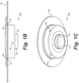
- FIGS. 1A-1C depict an exemplary integrated port 600, which may include a valve assembly 610 and a cover in the form of dome 620.
- Valve assembly 610 may include a main chamber 612 with a wall 615 having a lip 619. Lip 619 has an inner edge 619E.
- Main chamber 612 may have a top opening defined by edge 619E configured to face dome 620, and may accommodate a portion of dome 620, shown in this example as plug 621 of dome 620.
- Wall 615 of main chamber 612 may have one or more fluid holes 618 that may pass from main chamber 612 out of the valve assembly 610, e.g., providing for fluid entry and/or exit into a cavity of a medical implant radially inward of the port 600.
- a coil 616 may be located in a housing 614 which is separated from main chamber 612 by a needle stop 617, such that coil 616 is centered beneath main chamber 612.
- Dome 620 may have a patch 622, which may have a wider width than plug 621 and valve assembly 610, and may be integral with plug 621.
- a flange 626 between patch 622 and plug 621 may be configured to accommodate and interlock with lip 619 of valve assembly 610.
- dome 620 is illustrated with a step 624 that may be configured to interface with a wall of an implant (e.g., the shell of a tissue expander, breast implant, or other medical implant) into which the integrated port 600 may be installed, e.g., the dome 620 being located radially outside the implant wall and the main chamber 612 being radially inside the implant wall.
- FIG. 1B wherein wall 700 on a medical implant has an aperture 702 through which the port 600 (e.g., plug 621 of port 600) extends.
- the dome 620 may be coupled to the inner surface of a wall of an implant in use, e.g., via an adhesive or other fixation mechanism or material.
- the entire port 600 would be radially inward of the implant wall (e.g., the shell of a tissue expander, breast implant, or other medical implant).
- the port 600 may lack a step 624.
- the step 624 in FIG. 1A may be omitted, such that the flange 626 is between dome 620 and plug 621.
- the wall 700 of implant shown in FIG. 1B would be adjacent to the dome 620 such that the entirety of the port 600 is radially inward of wall 700. See also FIG. 5 discussed below.
- FIGS. 2A and 2B illustrate back and front views, respectively, of components of another exemplary port assembly.
- a needle stop of the integrated port which may also include any of the features of integrated port 600 discussed above.
- the components may include a first portion 710 configured to serve as a needle stop (e.g., similar to needle stop 617) and a second portion 715 coupled to the opposite side of the first portion 710 serving as the needle stop.
- the first portion 710 may comprise one or more materials configured to prevent or resist puncturing.
- the first portion 710 may overlay an electromagnetic coil (e.g., similar to coil 616) capable of emitting a RFID signal.
- the material(s) of first portion 710 may be non-ferromagnetic and may permit the transmission of RFID signals therethrough.
- Exemplary materials useful for first portion 710 may include, for example, polymers such as PEEK.
- Second portion 715 may comprise a RFID blocking material, such as aluminum or other suitable metal or metal alloy (which additionally may be non-ferromagnetic for MRI compatibility).
- the second portion 715 is positioned so as to block RFID transmission from the coil below the needle stop in the direction opposite first portion 710.
- second portion 715 may face the posterior side of the tissue expander or other medical implant, while the first portion 710 faces the anterior side of the tissue expander or other medical implant. This configuration is further illustrated in the example shown in FIGS.
- a second portion 815 similar to second portion 715 is positioned to block RFID signals from electromagnetic coil 816, e.g., wherein the coil 816 optionally may be between the RFID-blocking material of the second portion 815 and another material that allows the passage of RFID signals therethrough (e.g., a different material of a needle stop or other structure of the port assembly).
- FIG. 3 illustrates an exemplary reader or detector 750, also referred to herein as a port locator, that may be used for detecting integrated ports as disclosed herein.
- the detector may include one or more indicators, such as one or more lights, providing information about location, positioning, and/or orientation of the integrated port (and therefore positioning of the tissue expander or other medical implant that includes the integrated port) based on receiving RFID signals from the integrated port or lack of RFID signals received. For example, when RFID signals are not detected (e.g., when RFID-blocking material(s) prevents signals from an electromagnetic coil from being received by the detector 750), one or more of the indicator lights may illuminate to indicate that the tissue expander is misplaced.
- the tissue expander or other medical implant may have flipped its position such that the anterior side of the implant faces towards the chest of the patient.
- detector 750 may enable a user to determine whether the implant has shifted position so as to prevent access to the port.
- the user can then avoid inadvertently puncturing the tissue expander when the port is not accessible, and reposition the tissue expander before attempting to introduce and/or remove fluid via the port.
- the integrated ports herein may provide for ultrasound imaging for determining whether the medical implant, e.g., tissue expander, breast implant, gluteal implant, etc., is properly placed, e.g., so as to access the integrated port.
- a difference in materials of the components of the port such as different materials used for a needle stop component (e.g., first and second portions 710, 715 above) may allow for an ultrasound echo or echoes to determine the location, position, and/or orientation of the integrated port.
- FIG. 5 illustrates another exemplary port assembly 300 (alternatively referred to as integrated port 300) according to some aspects of the present disclosure, the port assembly 300 being coupled to the inner side of the wall 100 of a medical implant.
- the port assembly 300 includes a cover 320 (or dome) coupled to a lower portion or section that contains an electromagnetic coil 316.
- the lower portion or section includes a walled structure 315 coupled to an inner housing 314 that forms a chamber containing the coil 316.
- the port assembly 300 comprises a housing that includes the inner housing 314 as a first portion and the walled structure 315 as a second portion, wherein the coil 316 is between the first portion/inner housing 314 and the second portion/walled structure.
- the coil 316 may be coupled to (in electrical contact with) an integrated circuit chip (see, e.g., FIG. 6D discussed below).
- the lower portion or section may include one or more fluid holes to allow the port assembly 600 to serve as an injection port (e.g., the outer surface of the walled structure 315 facing the cover 320 providing a needle stop surface).
- port assembly 300 may include any of the features of integrated port 600 of FIGS. 1A-1C .
- the wall 100 of the medical implant may be a shell (e.g., flexible silicone shell) of a tissue expander or breast implant, for example.
- a user may introduce and/or remove fluid from the implant via port assembly 600 through a needle inserted through the wall 100 (e.g., through a silicone shell wall of the implant) and through the cover 320 (e.g., the cover comprising a self-sealing material).
- the inner housing 314 and the walled structure 315 may comprise different materials, one of inner housing 314 or walled structure 315 comprising a material that allows transmission of RFID signals and the other of inner housing 314 or walled structure 315 comprising an RFID-blocking material such as aluminum or other suitable metal or metal alloy, including other non-ferromagnetic metals and metal alloys.
- RFID signals emitted by the coil 316 may pass through the inner housing 314 for detection via an external reader or port locator external to a patient, while RFID are blocked from passing through walled structure 315.
- a user of the reader or port locator would have information regarding the position, location, and/or orientation of the port assembly 300 to determine if the implant has the proper position, location, and orientation in a patient.
- a medical professional additionally or alternatively may use ultrasound imaging to determine the position, location, and/or orientation of the port assembly 300, e.g., due to differences in ultrasound echoes of the different materials of inner housing 314 and walled structure 315.
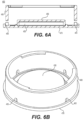
- FIGS. 6A-6D illustrate another exemplary port assembly 400, which as shown may serve as an injection port.
- the port assembly 400 may include components similar to those of port assembly 300 above.
- the cross-sectional view of FIG. 6A shows a lower portion of the port assembly 400 formed of a walled structure 460, a plate 470, and an inner housing 450 also coupled to the plate 470 to form an inner chamber 455.
- the walled structure 460 includes two or more holes 465 to allow for the passage of fluid therethrough.
- the upper surface of the walled structure 460 includes an aperture for receiving a cover, e.g., similar to cover 320 of port assembly 300 shown in FIG. 5 or dome 620 of integrated port 600 shown in FIG. 1A .
- FIG. 6B shows a perspective view of the port assembly 400 (without cover), illustrating four fluid holes 465 in a cylindrical walled structure 460.
- the port assembly 600 need not have a cylindrical shape and may have other suitable shapes such as square, rectangular, etc.
- FIG. 6C shows a top view of the plate 470 which includes several concentric ridges, the innermost ridge configured to abut the inner housing 450 as shown in the cross-sectional view of FIG. 6A .
- the port assembly 400 may comprise a housing that includes the inner housing 450 as a first portion, and the walled structure 460 and the plate 470 as a second portion
- FIG. 6D shows an exemplary electromagnetic coil 416 that may be housed within the inner chamber 455.
- the coil is coupled to an integrated circuit chip 425 to provide electrical contact between coil 416 and chip 425.
- chip 425 may store information unique to the port assembly 400 (e.g., a barcode, serial number, identifying information regarding the implant model or manufacturer, etc.) and/or a medical implant that includes the port assembly 400, and/or chip 425 may include one or more sensors for measuring various parameters as discussed above.
- Coil 416 (and optionally chip 425) may be between the first portion (inner housing 450) and the second portion (walled structure 460 and plate 470) of the housing.
- the inner housing 450 and the walled structure 460 and/or plate 470 may comprise different materials.
- one of inner housing 450 or walled structure 460 may comprise a material that allows transmission of RFID signals and the other of inner housing 450 or walled structure 460 may comprise an RFID-blocking material such as aluminum or other suitable metal or metal alloy, including other non-ferromagnetic metals and metal alloys.
- one of inner housing 450 or plate 470 may comprise a material that allows transmission of RFID signals and the other of inner housing 450 or plate 470 may comprise an RFID-blocking material such as aluminum or other suitable metal or metal alloy, including other non-ferromagnetic metals and metal alloys.
Landscapes
- Health & Medical Sciences (AREA)
- Life Sciences & Earth Sciences (AREA)
- Heart & Thoracic Surgery (AREA)
- Engineering & Computer Science (AREA)
- Public Health (AREA)
- Biomedical Technology (AREA)
- Veterinary Medicine (AREA)
- Animal Behavior & Ethology (AREA)
- General Health & Medical Sciences (AREA)
- Surgery (AREA)
- Pathology (AREA)
- Molecular Biology (AREA)
- Medical Informatics (AREA)
- Oral & Maxillofacial Surgery (AREA)
- Physics & Mathematics (AREA)
- Hematology (AREA)
- Anesthesiology (AREA)
- Pulmonology (AREA)
- Nuclear Medicine, Radiotherapy & Molecular Imaging (AREA)
- Biophysics (AREA)
- Human Computer Interaction (AREA)
- Electromagnetism (AREA)
- Dermatology (AREA)
- Cardiology (AREA)
- Transplantation (AREA)
- Vascular Medicine (AREA)
- Prostheses (AREA)
- Measuring And Recording Apparatus For Diagnosis (AREA)
- Media Introduction/Drainage Providing Device (AREA)
- External Artificial Organs (AREA)
- Electrotherapy Devices (AREA)
- Magnetic Resonance Imaging Apparatus (AREA)
Description
- The present disclosure relates generally to medical implant components useful for determining the location and/or orientation of the medical implant inside a subject, e.g., a patient. For example, the present disclosure includes port assemblies detectable with an external reader. The port assembly may be configured as an injection port for a medical implant including a tissue expander. Related methods of use of the port assemblies and medical implants are also described.
- Implantable medical devices may be implanted into patients for a variety of reasons, including, for example, to improve the clinical condition of a patient or to replace natural patient tissue. Injection ports of tissue expanders provide access to tissue expanders while implanted within a patient. Electromagnetic signals may be used to provide information on the location of an injection port of the tissue expander to facilitate access to the port. When a tissue expander is in an irregular position, such as when a tissue expander has flipped position, the injection port may be inaccessible to a physician or other medical professional, who could inadvertently puncture the tissue expander in an effort to access the injection port.
EP 3 556 317 A1 discloses implantable transponders comprising no ferromagnetic parts for use in medical implants; methods for using such transponders, readers for detecting such transponders and methods for using such readers are also described.
US 2019/0247138 A1 discloses a tissue expander comprising a shell defining a chamber, and having a flexible wall and a port disposed through the flexible wall. - The present disclosure includes port assemblies useful for providing access to a medical implant and/or determining the location and/or orientation of the implant inside a patient. Included herein are injection ports for tissue expanders comprising features that may provide for increased safety and/or decreased necessity for invasive procedures. While portions of this disclosure refer to tissue expanders and breast implants, the devices and methods disclosed herein may be used with other implantable medical devices, such as, e.g., other implants used in cosmetic and/or reconstruction procedures. Thus, for example, the port assemblies herein may provide distinctive signature(s) via electronic signal(s) and/or image(s) to assist a medical professional to determine the location and orientation of a medical implant in a non-invasive manner. The port assemblies herein may provide for introduction and/or removal of a fluid from the implant (e.g., an injection port of a tissue expander) but are not limited to fluid injection capability.
- The claimed invention is defined by
independent claims 1 and 14, and includes a tissue expander comprising an integrated port (also referred to herein as a port or port assembly), wherein the integrated port comprises a housing comprising a first portion coupled to a second portion, wherein the first portion and the second portion comprise different materials; and a self-sealing cover (e.g., a dome) over an opening into the housing; wherein the first portion faces the cover and allows transmission of electromagnetic signals through the first portion, the first portion being between the second portion and the cover; and wherein the second portion prevents transmission of electromagnetic signals through the second portion in a direction away from the cover. In some aspects, the integrated port further comprises an electromagnetic coil between the first portion and the second portion of the housing. Each of the first portion of the housing and the cover may comprise a polymer, e.g., the same polymer or different polymers. Additionally or alternatively, the second portion of the housing may comprise a non-ferromagnetic metal or non-ferromagnetic metal alloy. In at least one example, the second portion of the housing comprises aluminum. In some examples, the integrated port does not comprise any ferromagnetic materials. - In at least one example, the housing forms a chamber configured to receive a fluid, the chamber comprising the first portion and a second portion; and the integrated port comprises a coil between the first portion and the second portion. The first portion may be configured as a needle stop. The first portion may allow transmission of electromagnetic signals from the coil while the second portion prevents transmission of electromagnetic signals from the coil. As mentioned above, the first portion may comprise a polymer and/or the second portion may comprise a non-ferromagnetic metal or non-ferromagnetic metal alloy. For example, the second portion may comprise aluminum and/or the first portion may comprise a polymer such as poly-ether-ether-ketone. The cover is self-sealing, e.g., when an injection device such as a needle punctures the cover for introducing or removing fluid from the integrated port. The coil may be contained within a fluid-tight compartment of the housing that prevents contact between the coil and a fluid within the chamber. As mentioned above, in some examples, the integrated port does not comprise any ferromagnetic materials. In at least one example, the housing is cylindrical in shape.
- The present disclosure also includes medical implants comprising the integrated ports herein. For example, the implant may comprise a flexible shell, and the cover (e.g., dome) of the integrated port may be coupled to an inner surface or an outer surface of the shell. For example, the cover may be coupled to the shell with an adhesive. In at least one example, the shell of the implant comprises silicone, and the cover of the integrated port comprises silicone or poly-ether-ether-ketone. According to the claimed invention, the medical implant is a tissue expander.
- The present disclosure also includes non-invasive methods of locating the integrated ports herein, e.g., providing information about the position, location, and/or orientation of a medical implant that includes an integrated port as disclosed herein. The claimed non-invasive method includes ultrasound imaging and analyzing echoes from the integrated port, and optionally analyzing a presence or absence of RFID signals from the integrated port to determine an orientation of the implant relative to tissue of a patient.
- Further disclosed herein is an integrated port comprising a chamber configured to receive a fluid, the chamber comprising a first portion and a second portion, wherein the first portion comprises a material different from a material of the second portion, one of the materials being a non-ferromagnetic metal; a coil between the first portion and the second portion; and a cover (e.g., a dome) covering an opening into the chamber; wherein the first portion faces the dome, the first portion being configured as a needle stop; and wherein the first portion allows transmission of electromagnetic signals from the coil while the second portion prevents transmission of electromagnetic signals from the coil. In some examples, the integrated port further comprises an integrated circuit chip coupled to the coil, for example soldered to the coil. Medical implants comprising such integrated ports may comprise a flexible shell, e.g., the cover of the integrated port being coupled to an inner surface or an outer surface of the shell.
- The accompanying drawings, which are incorporated in and constitute a part of this application, illustrate various examples and together with the description, serve to explain the principles of the present disclosure. Any features of an embodiment or example described herein (e.g., device, method, etc.) may be combined with any other embodiment or example, and are encompassed by the present disclosure.
-
FIGS. 1A-1C show an exemplary integrated port, according to some aspects of the present disclosure. -
FIGS. 2A and 2B show portions of an exemplary integrated port, according to some aspects of the present disclosure. -
FIG. 3 shows an exemplary detector device, according to aspects of the present disclosure. -
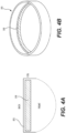
FIGS. 4A and 4B show portions of an exemplary integrated port, according to some aspects of the present disclosure. -
FIG. 5 shows an exemplary port coupled to a medical implant, according to some aspects of the present disclosure. -
FIGS. 6A-6D illustrate another exemplary port, according to some aspects of the present disclosure. - Aspects of the present disclosure are described in greater detail below. The terms and definitions as used and clarified herein are intended to represent the meaning within the present disclosure. The terms and definitions provided herein control, if in conflict with terms and/or definitions incorporated by reference.
- The singular forms "a," "an," and "the" include plural reference unless the context dictates otherwise. The terms "approximately" and "about" refer to being nearly the same as a referenced number or value. As used herein, the terms "approximately" and "about" generally should be understood to encompass ± 5% of a specified amount or value.
- As used herein, the term "posterior" refers to the back of a patient, and the term "anterior" refers to front of a patient. Thus, the posterior side of an implant such as a tissue expander or breast implant is the side of the implant facing the chest wall, while the anterior side is the opposite side closest to the skin.
- The present disclosure generally relates to medical implants, features of medical implants, port assemblies useful for medical implants, and transponders and sensors for use with such implants and port assemblies, and methods of using such port assemblies, transponders, sensors, and implants. Aspects of the present disclosure may be useful for locating medical devices that may be implanted in the patient. Such implantable medical devices may include, but are not limited to, tissue expanders, breast implants, gluteal implants, and other medical devices in the field of aesthetic or reconstructive surgery, as well as other types of medical devices configured for temporary or permanent implantation inside a patient. Various aspects of the present disclosure may be used with and/or include one or more features of transponders, valve assemblies, integrated ports, and readers disclosed in
U.S. Patent No. 10,176,412 - In the invention, the medical implant is a tissue expander. Tissue expanders of the present disclosure may be inflated manually and/or electronically, e.g., with a syringe or other suitable device for introducing and withdrawing a fluid (e.g., a liquid or gaseous fluid) or gel into the tissue expanders. Tissue expanders and other medical implants according to the present disclosure may comprise a port having components useful for determining the location and/or orientation of the tissue expander or other medical implant in a patient, e.g., an integrated port. The terms "integrated port" and "port assembly" are used interchangeably herein to describe ports with features that facilitate identifying the location, position, and/or orientation of a medical implant that includes the integrated port or port assembly. The integrated port may include features to facilitate locating and identifying the port, including in cases when the tissue expander or other medical device is misplaced or suspected of being misplaced, in a non-invasive manner.
- For example, the integrated port may comprise an electromagnetic coil configured to emit electromagnetic signals, e.g., radio-frequency identification (RFID) signals, and/or ultrasonic signals. Optionally, the coil may be coupled to an integrated circuit chip and/or other electronic components, including sensors configured to assure medical device integrity such as rupture detection and/or measure patient vitals and/or parameters such as temperature, pressure, heart rate, respiratory rate, and/or pH, among others.
- The integrated ports herein allow for non-invasive methods of detecting if a tissue expander implanted in a patient has been misplaced (e.g., flipped such that the port is in a posterior position towards the patient's chest rather than an anterior position towards the skin surface) and thus whether an additional medical procedure should be performed to reposition the tissue expander. For example, the methods herein may prevent or reduce the risk of inadvertently puncturing a tissue expander, creating a deflation and/or resulting in other complications for the patient. The present disclosure also includes methods of locating the port of a tissue expander via ultrasound imaging, including locating the port independent of RFID location.
- One or more portions of the integrated port (or port assembly) may comprise one or more non-ferromagnetic materials. Exemplary non-ferromagnetic materials include, but are not limited to, polymers such as poly-ether-ether-ketone (PEEK), polycarbonate, and other plastics; ceramic; silica (e.g., glass); and non-ferromagnetic metals such as aluminum and copper, and alloys of these metals, as well as other metals and metal alloys that are non-ferromagnetic. In some examples, the integrated port may comprise nickel. For example, the integrated port (or port assembly) may comprise one or more materials, all of which may be non-ferromagnetic, to maintain magnetic resonance imaging (MRI) compatibility. The structure of the integrated port and combination of materials may provide for distinctive signals and/or images to assist a medical professional in determining the location, position, and/or orientation of the medical implant via an external reader and/or imaging.
- The integrated port comprises at least two different materials. For example, the integrated port may comprise two different metals or metal alloys, a polymer and a metal or metal alloy, or two different polymers, among other combinations of materials. In at least one example, the integrated port comprises a polymer, such as PEEK, and an additional material that has capabilities of RFID blocking, such as aluminum. See, e.g.,
FIGS. 6A and 6B discussed below. The RFID-blocking material may be positioned so as to block an RFID signal of the integrated port in at least one direction. - In the case of an injection port for a tissue expander, for example, the integrated port may include an electromagnetic coil proximate a needle stop. In at least one example, the RFID-blocking material may be placed adjacent to or on the bottom of a needle stop of the integrated port, or as a "coin" within the needle stop. The coil that emits an RFID signal to assist in locating the integrated port may be proximate, e.g., sit on top of, this RFID-blocking material. Accordingly, the RFID signal may only be detected by a suitable reader/port locator if the RFID-blocking material is not positioned between the coil and the reader/port locator. If the tissue expander has flipped such that the RFID blocking material is between the coil and the reader/port locator, signals emitted from the integrated port may be blocked from detection by the reader/port locator. Failure to detect the integrated port via the port locator may turn on an indicator light of the port locator, e.g., to indicate that the tissue expander is incorrectly positioned, such as due to having flipped or otherwise becoming misplaced.
- According to the claimed invention, port location is performed via ultrasound imaging. For example, a difference in materials included in the integrated port allows for the ultrasound echo to differ. The materials may have different densities, chemical compositions, and/or structure, for example, that provide different signatures via ultrasound imaging. This difference in materials allows a medical professional to analyze ultrasound images of a patient to determine the location, position, and/or orientation of a medical implant in a non-invasive manner.
- Ultrasound, also referred to as sonography, is a non-invasive medical imaging technique useful for observing the environment surrounding a medical implant. Ultrasound can be used to capture internal images of the body, such as muscles, organs, blood vessels, and other tissue, in addition to implants. An ultrasound machine typically includes a transducer and a processor, such as a central processing unit of a computer, connected to a display, such as a monitor. To collect images, the transducer may be placed on a patient's skin and passed over an area of the body to be imaged, wherein sound waves are emitted from the transducer. When a medical professional obtains images using an ultrasound system, the transducer sends a sound wave with an amplitude that changes due to reflection and transmissions as the sound wave contacts different types of anatomical structure. Reflection and transmission coefficients of the sound waves may be used to describe the environment around an implant. The frequency of the sound waves is typically above 20 kHz, e.g., frequencies ranging between 1 MHz and 10 MHz. The sound waves pass through the body and are at least partially reflected back to the transducer after they bounce off relatively more dense structures, such as bodily tissue or an implant. Echo lines in an ultrasound image are a sign of inhomogeneities in an environment. The processor measures the echo intensities and speed of the sound waves, and converts these measurements to electronic images. The ultrasound images provide an indication of anatomy, e.g., wherein brighter areas correspond to features with greater density. As a sound wave has an initial amplitude that undergoes reflections and transmissions depending on the patient's anatomy and medical implants therein, the reflection and transmission characteristics may be analyzed to calculate describe characteristics of medical implants, including location, position, and/or orientation information.
- Ultrasound imaging may be used in addition to, or in place of, electromagnetic detection such as RFID detection. In the case of an integrated port comprising silicone and a polymer (e.g., PEEK), for example, ultrasound may be used to visualize the integrated port independent of RFID detection. This feature may provide detection capabilities for medical implants that do not have an electromagnetic coil. For example, a tissue expander may include an integrated port in the form of an injection port comprising two different materials (e.g., PEEK and silicone, or other combination of different materials) that allow for determining the location, position, and/or orientation of the port via non-invasive ultrasound imaging, independent of locating the integrated port via RFID signal.
- In some embodiments, the present disclosure provides an integrated port, comprising: a chamber configured to receive a fluid, the chamber comprising a first portion and a second portion, wherein the first portion comprises a material different from a material of the second portion, one of the materials being a non-ferromagnetic material; a coil between the first portion and the second portion; and a dome covering an opening into the chamber; wherein the first portion faces the dome, the first portion being configured as a needle stop; and wherein the first portion allows transmission of electromagnetic signals from the coil while the second portion prevents transmission of electromagnetic signals from the coil. The integrated port may comprise an integrated circuit chip coupled to the coil, for example soldered to the coil. The integrated port may be part of a medical implant comprising a flexible shell, the cover of the integrated port being coupled to an inner surface or an outer surface of the shell.
- Reference is made to the following figures as examples of the present disclosure, but it is understood that the present disclosure is limited to the particular structures and examples illustrated.
-
FIGS. 1A-1C depict an exemplaryintegrated port 600, which may include avalve assembly 610 and a cover in the form ofdome 620.Valve assembly 610 may include amain chamber 612 with awall 615 having alip 619.Lip 619 has aninner edge 619E.Main chamber 612 may have a top opening defined byedge 619E configured to facedome 620, and may accommodate a portion ofdome 620, shown in this example asplug 621 ofdome 620.Wall 615 ofmain chamber 612 may have one or morefluid holes 618 that may pass frommain chamber 612 out of thevalve assembly 610, e.g., providing for fluid entry and/or exit into a cavity of a medical implant radially inward of theport 600. Acoil 616 may be located in ahousing 614 which is separated frommain chamber 612 by aneedle stop 617, such thatcoil 616 is centered beneathmain chamber 612. -
Dome 620 may have apatch 622, which may have a wider width thanplug 621 andvalve assembly 610, and may be integral withplug 621. Aflange 626 betweenpatch 622 and plug 621 may be configured to accommodate and interlock withlip 619 ofvalve assembly 610. In this example,dome 620 is illustrated with astep 624 that may be configured to interface with a wall of an implant (e.g., the shell of a tissue expander, breast implant, or other medical implant) into which theintegrated port 600 may be installed, e.g., thedome 620 being located radially outside the implant wall and themain chamber 612 being radially inside the implant wall. This is illustrated inFIG. 1B whereinwall 700 on a medical implant has anaperture 702 through which the port 600 (e.g., plug 621 of port 600) extends. - In some examples, the
dome 620 may be coupled to the inner surface of a wall of an implant in use, e.g., via an adhesive or other fixation mechanism or material. In such examples, theentire port 600 would be radially inward of the implant wall (e.g., the shell of a tissue expander, breast implant, or other medical implant). In such cases, theport 600 may lack astep 624. For example, thestep 624 inFIG. 1A may be omitted, such that theflange 626 is betweendome 620 and plug 621. In this example, thewall 700 of implant shown inFIG. 1B would be adjacent to thedome 620 such that the entirety of theport 600 is radially inward ofwall 700. See alsoFIG. 5 discussed below. -
Valve assembly 610 may comprise biocompatible, non-ferromagnetic material(s), such as PEEK, silicone, and/or other polymer(s), and/or one or more RFID blocking materials such as aluminum, nickel, copper, and/or alloys thereof.Main chamber 612 may be sized, shaped, and configured to receive fluids from, e.g., a cannula, syringe, or other fluid deposition device. Needle stop 617 ofmain chamber 612 may be configured to prevent or resist puncturing by such a fluid deposition device (e.g., a needle of a syringe). For example, needle stop 617 may comprise one or more materials having a density, hardness, and/or thickness configured to prevent or resist puncturing by a needle. According to some aspects of the present disclosure,integrated port 600 may include aneedle stop 617 that comprises a polymer such as PEEK and an RFID-blocking material such as aluminum opposite theneedle stop 617. -
Coil 616 may be an electromagnetic coil positioned within a separate chamber, e.g., provided in this example byhousing 614.Housing 614 may be fluid-tight so as to prevent fluids from enteringhousing 614 and coming into contact withcoil 616. Housing may be cylindrical, as shown, and may be coaxial withmain chamber 612, such thatcoil 616 is also coaxial withmain chamber 612. In this manner, the location ofcoil 616 may be used to locate the center, or the approximate center, ofmain chamber 612 andhousing 614.Housing 614 is depicted as having a smaller circumference than, e.g.main chamber 612. However, in some examples,housing 614 may have dimensions as large or nearly as large asmain chamber 612.Coil 616 optionally may be coupled to a chip, e.g., an integrated circuit chip as mentioned above. For example, the chip may be soldered or otherwise in electronic contact with the inner or outer surface ofcoil 616. Plug 621 ofdome 620 may be sized and shaped to snugly interlock with, e.g.,lip 619 ofmain chamber 612.Dome 620 may comprise a biocompatible material such as silicone with self-sealing capabilities. -
FIGS. 2A and 2B illustrate back and front views, respectively, of components of another exemplary port assembly. In this example is shown a needle stop of the integrated port, which may also include any of the features ofintegrated port 600 discussed above. The components may include afirst portion 710 configured to serve as a needle stop (e.g., similar to needle stop 617) and asecond portion 715 coupled to the opposite side of thefirst portion 710 serving as the needle stop. Thefirst portion 710 may comprise one or more materials configured to prevent or resist puncturing. Thefirst portion 710 may overlay an electromagnetic coil (e.g., similar to coil 616) capable of emitting a RFID signal. The material(s) offirst portion 710 may be non-ferromagnetic and may permit the transmission of RFID signals therethrough. Exemplary materials useful forfirst portion 710 may include, for example, polymers such as PEEK. -
Second portion 715 may comprise a RFID blocking material, such as aluminum or other suitable metal or metal alloy (which additionally may be non-ferromagnetic for MRI compatibility). Thesecond portion 715 is positioned so as to block RFID transmission from the coil below the needle stop in the direction oppositefirst portion 710. For example, in the case of a tissue expander or other medical implant,second portion 715 may face the posterior side of the tissue expander or other medical implant, while thefirst portion 710 faces the anterior side of the tissue expander or other medical implant. This configuration is further illustrated in the example shown inFIGS. 4A and 4B , wherein asecond portion 815 similar tosecond portion 715 is positioned to block RFID signals fromelectromagnetic coil 816, e.g., wherein thecoil 816 optionally may be between the RFID-blocking material of thesecond portion 815 and another material that allows the passage of RFID signals therethrough (e.g., a different material of a needle stop or other structure of the port assembly). -
FIG. 3 illustrates an exemplary reader ordetector 750, also referred to herein as a port locator, that may be used for detecting integrated ports as disclosed herein. In some examples, the detector may include one or more indicators, such as one or more lights, providing information about location, positioning, and/or orientation of the integrated port (and therefore positioning of the tissue expander or other medical implant that includes the integrated port) based on receiving RFID signals from the integrated port or lack of RFID signals received. For example, when RFID signals are not detected (e.g., when RFID-blocking material(s) prevents signals from an electromagnetic coil from being received by the detector 750), one or more of the indicator lights may illuminate to indicate that the tissue expander is misplaced. For example, the tissue expander or other medical implant may have flipped its position such that the anterior side of the implant faces towards the chest of the patient. In this way,detector 750 may enable a user to determine whether the implant has shifted position so as to prevent access to the port. In the case of a tissue expander where the integrated port is an injection port, the user can then avoid inadvertently puncturing the tissue expander when the port is not accessible, and reposition the tissue expander before attempting to introduce and/or remove fluid via the port. - Additionally, as mentioned above, the integrated ports herein may provide for ultrasound imaging for determining whether the medical implant, e.g., tissue expander, breast implant, gluteal implant, etc., is properly placed, e.g., so as to access the integrated port. A difference in materials of the components of the port, such as different materials used for a needle stop component (e.g., first and
second portions -
FIG. 5 illustrates another exemplary port assembly 300 (alternatively referred to as integrated port 300) according to some aspects of the present disclosure, theport assembly 300 being coupled to the inner side of thewall 100 of a medical implant. Theport assembly 300 includes a cover 320 (or dome) coupled to a lower portion or section that contains anelectromagnetic coil 316. As shown, the lower portion or section includes awalled structure 315 coupled to aninner housing 314 that forms a chamber containing thecoil 316. Thus, theport assembly 300 comprises a housing that includes theinner housing 314 as a first portion and thewalled structure 315 as a second portion, wherein thecoil 316 is between the first portion/inner housing 314 and the second portion/walled structure. In some examples, thecoil 316 may be coupled to (in electrical contact with) an integrated circuit chip (see, e.g.,FIG. 6D discussed below). Optionally, the lower portion or section may include one or more fluid holes to allow theport assembly 600 to serve as an injection port (e.g., the outer surface of thewalled structure 315 facing thecover 320 providing a needle stop surface). Thus,port assembly 300 may include any of the features ofintegrated port 600 ofFIGS. 1A-1C . Thewall 100 of the medical implant may be a shell (e.g., flexible silicone shell) of a tissue expander or breast implant, for example. When theport assembly 600 is configured to serve as an injection port, a user may introduce and/or remove fluid from the implant viaport assembly 600 through a needle inserted through the wall 100 (e.g., through a silicone shell wall of the implant) and through the cover 320 (e.g., the cover comprising a self-sealing material). - According to some aspects of the present disclosure, the
inner housing 314 and thewalled structure 315 may comprise different materials, one ofinner housing 314 orwalled structure 315 comprising a material that allows transmission of RFID signals and the other ofinner housing 314 orwalled structure 315 comprising an RFID-blocking material such as aluminum or other suitable metal or metal alloy, including other non-ferromagnetic metals and metal alloys. Thus, for example, RFID signals emitted by thecoil 316 may pass through theinner housing 314 for detection via an external reader or port locator external to a patient, while RFID are blocked from passing throughwalled structure 315. In this way, a user of the reader or port locator would have information regarding the position, location, and/or orientation of theport assembly 300 to determine if the implant has the proper position, location, and orientation in a patient. A medical professional additionally or alternatively may use ultrasound imaging to determine the position, location, and/or orientation of theport assembly 300, e.g., due to differences in ultrasound echoes of the different materials ofinner housing 314 andwalled structure 315. -
FIGS. 6A-6D illustrate anotherexemplary port assembly 400, which as shown may serve as an injection port. Theport assembly 400 may include components similar to those ofport assembly 300 above. For example, the cross-sectional view ofFIG. 6A shows a lower portion of theport assembly 400 formed of awalled structure 460, aplate 470, and aninner housing 450 also coupled to theplate 470 to form aninner chamber 455. Thewalled structure 460 includes two ormore holes 465 to allow for the passage of fluid therethrough. The upper surface of thewalled structure 460 includes an aperture for receiving a cover, e.g., similar to cover 320 ofport assembly 300 shown inFIG. 5 ordome 620 ofintegrated port 600 shown inFIG. 1A .FIG. 6B shows a perspective view of the port assembly 400 (without cover), illustrating fourfluid holes 465 in a cylindricalwalled structure 460. Theport assembly 600 need not have a cylindrical shape and may have other suitable shapes such as square, rectangular, etc.FIG. 6C shows a top view of theplate 470 which includes several concentric ridges, the innermost ridge configured to abut theinner housing 450 as shown in the cross-sectional view ofFIG. 6A . Thus, theport assembly 400 may comprise a housing that includes theinner housing 450 as a first portion, and thewalled structure 460 and theplate 470 as a second portion -
FIG. 6D shows an exemplaryelectromagnetic coil 416 that may be housed within theinner chamber 455. The coil is coupled to anintegrated circuit chip 425 to provide electrical contact betweencoil 416 andchip 425. Optionally,chip 425 may store information unique to the port assembly 400 (e.g., a barcode, serial number, identifying information regarding the implant model or manufacturer, etc.) and/or a medical implant that includes theport assembly 400, and/orchip 425 may include one or more sensors for measuring various parameters as discussed above. Coil 416 (and optionally chip 425) may be between the first portion (inner housing 450) and the second portion (walled structure 460 and plate 470) of the housing. - According to some aspects of the present disclosure, the
inner housing 450 and thewalled structure 460 and/orplate 470 may comprise different materials. For example, one ofinner housing 450 orwalled structure 460 may comprise a material that allows transmission of RFID signals and the other ofinner housing 450 orwalled structure 460 may comprise an RFID-blocking material such as aluminum or other suitable metal or metal alloy, including other non-ferromagnetic metals and metal alloys. Additionally or alternatively, one ofinner housing 450 orplate 470 may comprise a material that allows transmission of RFID signals and the other ofinner housing 450 orplate 470 may comprise an RFID-blocking material such as aluminum or other suitable metal or metal alloy, including other non-ferromagnetic metals and metal alloys. In some examples, thewalled structure 460 and theplate 470 may both comprise an RFID blocking material while theinner housing 450 comprises a material that permits transmission of RFID signals therethrough, e.g., a polymer such as PEEK. Thus, for example, RFID signals emitted by the coil 416 (disposed between theinner housing 450 and the plate 470) may pass through theinner housing 450 for detection via an external reader or port locator external to a patient, while RFID are blocked from passing throughplate 470 andwalled structure 460. A user of the reader or port locator would have information regarding the position, location, and/or orientation of theport assembly 400 to determine if the implant has the proper position, location, and orientation in a patient. A medical professional additionally or alternatively may use ultrasound imaging to determine the position, location, and/or orientation of theport assembly 400, e.g., due to differences in ultrasound echoes of the different materials ofinner housing 450,walled structure 460, and/orplate 470.
Claims (14)
- A tissue expander comprising an integrated port, wherein the integrated port (300, 400, 600) comprises:a self-sealing cover (320, 620) over an opening into a housing (314, 614);characterized in thatthe housing comprises a first portion (710) coupled to a second portion (715, 815), wherein the first portion and the second portion comprise different materials; andwherein the first portion faces the cover and allows transmission of electromagnetic signals through the first portion, the first portion being between the second portion and the cover; andwherein the second portion prevents transmission of electromagnetic signals through the second portion in a direction away from the cover.
- The tissue expander of claim 1, wherein each of the first portion of the housing and the cover comprises a polymer, optionally wherein the first portion and the cover comprise different polymers.
- The tissue expander of any one of the preceding claims, wherein the second portion of the housing comprises a non-ferromagnetic metal or non-ferromagnetic metal alloy.
- The tissue expander of any one of the preceding claims, the integrated port further comprising an electromagnetic coil (316, 416, 616, 816) between the first portion and the second portion of the housing.
- The tissue expander of claim 4, the integrated port further comprising an integrated circuit chip (425) coupled to the coil, for example soldered to the coil.
- The tissue expander of any one of claims 4 and 5, wherein:the housing forms a chamber (612) configured to receive a fluid, the chamber comprising the first portion and the second portion;the first portion (710) is configured as a needle stop (617, 710); andthe first portion allows transmission of electromagnetic signals from the coil while the second portion prevents transmission of electromagnetic signals from the coil.
- The tissue expander of any one of claims 4 to 6, wherein the coil is contained within a fluid-tight compartment of the housing (614) that prevents contact between the coil and a fluid within the chamber.
- The tissue expander of any one of the preceding claims, wherein the first portion comprises a polymer and the second portion comprises a non-ferromagnetic metal or non-ferromagnetic metal alloy.
- The tissue expander of any one of the preceding claims, wherein the second portion comprises aluminum and/or wherein the first portion comprises poly-ether-ether-ketone.
- The tissue expander of any one of the preceding claims, wherein the integrated port does not comprise any ferromagnetic materials.
- The tissue expander of any one of the preceding claims, wherein the housing is cylindrical in shape.
- The tissue expander of any one of the preceding claims, wherein the implant comprises a flexible shell, and the cover of the integrated port is coupled to an inner surface or an outer surface of the shell, optionally wherein the cover is coupled to the shell with an adhesive.
- The tissue expander of any one of claims 12, wherein the shell comprises silicone, and the cover of the integrated port comprises silicone or poly-ether-ether-ketone.
- A non-invasive method of locating the integrated port of the tissue expander of any one of the preceding claims, wherein the method comprises ultrasound imaging and analyzing echoes from the integrated port, optionally wherein the method further comprises analyzing a presence or absence of RFID signals from the integrated port to determine an orientation of the implant relative to tissue of a patient.
Applications Claiming Priority (2)
| Application Number | Priority Date | Filing Date | Title |
|---|---|---|---|
| US202163134858P | 2021-01-07 | 2021-01-07 | |
| PCT/IB2022/050090 WO2022149086A1 (en) | 2021-01-07 | 2022-01-06 | Medical implant port assemblies and related methods |
Publications (3)
| Publication Number | Publication Date |
|---|---|
| EP4262611A1 EP4262611A1 (en) | 2023-10-25 |
| EP4262611C0 EP4262611C0 (en) | 2025-04-09 |
| EP4262611B1 true EP4262611B1 (en) | 2025-04-09 |
Family
ID=79686786
Family Applications (1)
| Application Number | Title | Priority Date | Filing Date |
|---|---|---|---|
| EP22700195.5A Active EP4262611B1 (en) | 2021-01-07 | 2022-01-06 | Medical implant port assemblies and related methods |
Country Status (8)
| Country | Link |
|---|---|
| US (1) | US20240057889A1 (en) |
| EP (1) | EP4262611B1 (en) |
| KR (1) | KR20230129257A (en) |
| CN (1) | CN117042717A (en) |
| CA (1) | CA3207648A1 (en) |
| ES (1) | ES3035386T3 (en) |
| IL (1) | IL304010A (en) |
| WO (1) | WO2022149086A1 (en) |
Families Citing this family (3)
| Publication number | Priority date | Publication date | Assignee | Title |
|---|---|---|---|---|
| US12611282B2 (en) * | 2021-08-18 | 2026-04-28 | Mentor Worldwide Llc | Tissue expanders having fill port assemblies and drain port assemblies that are isolated from one another for preventing cross-contamination of fluids |
| CN119604252A (en) * | 2022-07-26 | 2025-03-11 | 艾鲁森特医疗股份有限公司 | System and method for wireless positioning |
| EP4642323A1 (en) * | 2023-02-24 | 2025-11-05 | Matchstick LLC | Systems, methods, and apparatus for localizing and accessing implanted port |
Family Cites Families (4)
| Publication number | Priority date | Publication date | Assignee | Title |
|---|---|---|---|---|
| CA3013698A1 (en) * | 2016-02-09 | 2017-08-17 | Establishment Labs S.A. | Transponders and sensors for implantable medical devices and methods of use thereof |
| US20180336381A1 (en) * | 2017-05-17 | 2018-11-22 | Ramin Homanfar | Intravenous access port with radio frequency based locating means |
| US11382709B2 (en) * | 2018-02-09 | 2022-07-12 | Mentor Worldwide Llc | Tissue expander |
| EP3820559B1 (en) * | 2018-08-02 | 2025-06-18 | Bard Peripheral Vascular, Inc. | Implantable port placement system including low-scarring exterior |
-
2022
- 2022-01-06 WO PCT/IB2022/050090 patent/WO2022149086A1/en not_active Ceased
- 2022-01-06 CN CN202280018324.0A patent/CN117042717A/en active Pending
- 2022-01-06 ES ES22700195T patent/ES3035386T3/en active Active
- 2022-01-06 KR KR1020237026372A patent/KR20230129257A/en active Pending
- 2022-01-06 EP EP22700195.5A patent/EP4262611B1/en active Active
- 2022-01-06 CA CA3207648A patent/CA3207648A1/en active Pending
- 2022-01-06 US US18/270,618 patent/US20240057889A1/en active Pending
- 2022-01-06 IL IL304010A patent/IL304010A/en unknown
Also Published As
| Publication number | Publication date |
|---|---|
| IL304010A (en) | 2023-08-01 |
| CA3207648A1 (en) | 2022-07-14 |
| EP4262611C0 (en) | 2025-04-09 |
| EP4262611A1 (en) | 2023-10-25 |
| WO2022149086A1 (en) | 2022-07-14 |
| CN117042717A (en) | 2023-11-10 |
| ES3035386T3 (en) | 2025-09-02 |
| US20240057889A1 (en) | 2024-02-22 |
| KR20230129257A (en) | 2023-09-07 |
Similar Documents
| Publication | Publication Date | Title |
|---|---|---|
| US20240057889A1 (en) | Medical implant port assemblies and related methods | |
| US12406161B2 (en) | Transponders and sensors for implantable medical devices and methods of use thereof | |
| US9492638B2 (en) | Implements for identifying sheath migration | |
| KR101248077B1 (en) | Guide block for biopsy or surgical devices | |
| AU743966B2 (en) | Intrabody measurement | |
| CN100482151C (en) | System for detecting liquid change and sensor device thereof | |
| EP3307173B1 (en) | System for identifying cancerous tissue | |
| CA2653518A1 (en) | Locator system for implanted access port with rfid tag | |
| JPH10512462A (en) | Impedance imaging device and multi-element probe | |
| O'Toole et al. | Imaging spectrum of breast implant complications: mammography, ultrasound, and magnetic resonance imaging | |
| WO2007117478A2 (en) | Marking and scanning surical targets in vivo | |
| JP2019535339A (en) | System and method for localization and imaging of magnetic potential lesions | |
| CN115998336A (en) | System and method for displaying echoneedle position | |
| US20080071149A1 (en) | Method and system of representing a medical event | |
| HK40093989A (en) | Medical implant port assemblies and related methods | |
| HK40093989B (en) | Medical implant port assemblies and related methods | |
| KR20090123363A (en) | Ultrasound system and method for detecting extravascular leakage | |
| KR20100091866A (en) | Bone marker apparatus for navigation surgery and navigation method using the same | |
| JP2020531075A (en) | Medical imaging systems and methods | |
| US20190313998A1 (en) | Systems and Methods for Facilitating Auscultation Detection of Vascular Conditions | |
| KR102063271B1 (en) | Ultrasound treatment apparatus and driving method thereof | |
| WO2024100495A1 (en) | Systems, devices and methods of detecting the location of injection ports in mammary implants using ultrasonic waves and employing reverberation effects | |
| US11857369B1 (en) | System and method for generation and display of ultrasound imaging data | |
| Schrading | MR-Guided Breast Intervention | |
| Seyffer | Investigating the precision of an induction-based localization system for medical applications |
Legal Events
| Date | Code | Title | Description |
|---|---|---|---|
| STAA | Information on the status of an ep patent application or granted ep patent |
Free format text: STATUS: UNKNOWN |
|
| STAA | Information on the status of an ep patent application or granted ep patent |
Free format text: STATUS: THE INTERNATIONAL PUBLICATION HAS BEEN MADE |
|
| PUAI | Public reference made under article 153(3) epc to a published international application that has entered the european phase |
Free format text: ORIGINAL CODE: 0009012 |
|
| STAA | Information on the status of an ep patent application or granted ep patent |
Free format text: STATUS: REQUEST FOR EXAMINATION WAS MADE |
|
| 17P | Request for examination filed |
Effective date: 20230720 |
|
| AK | Designated contracting states |
Kind code of ref document: A1 Designated state(s): AL AT BE BG CH CY CZ DE DK EE ES FI FR GB GR HR HU IE IS IT LI LT LU LV MC MK MT NL NO PL PT RO RS SE SI SK SM TR |
|
| REG | Reference to a national code |
Ref country code: HK Ref legal event code: DE Ref document number: 40093989 Country of ref document: HK |
|
| DAV | Request for validation of the european patent (deleted) | ||
| DAX | Request for extension of the european patent (deleted) | ||
| STAA | Information on the status of an ep patent application or granted ep patent |
Free format text: STATUS: EXAMINATION IS IN PROGRESS |
|
| 17Q | First examination report despatched |
Effective date: 20240603 |
|
| REG | Reference to a national code |
Free format text: PREVIOUS MAIN CLASS: A61B0090000000 Ref country code: DE Ref legal event code: R079 Ref document number: 602022012884 Country of ref document: DE Ipc: A61M0039040000 |
|
| GRAP | Despatch of communication of intention to grant a patent |
Free format text: ORIGINAL CODE: EPIDOSNIGR1 |
|
| STAA | Information on the status of an ep patent application or granted ep patent |
Free format text: STATUS: GRANT OF PATENT IS INTENDED |
|
| RIC1 | Information provided on ipc code assigned before grant |
Ipc: A61F 2/12 20060101ALI20241007BHEP Ipc: A61F 2/00 20060101ALI20241007BHEP Ipc: A61B 90/98 20160101ALI20241007BHEP Ipc: A61B 90/00 20160101ALI20241007BHEP Ipc: A61B 5/06 20060101ALI20241007BHEP Ipc: A61M 39/02 20060101ALI20241007BHEP Ipc: A61M 39/04 20060101AFI20241007BHEP |
|
| INTG | Intention to grant announced |
Effective date: 20241031 |
|
| RAP3 | Party data changed (applicant data changed or rights of an application transferred) |
Owner name: ESTABLISHMENT LABS S.A. |
|
| GRAS | Grant fee paid |
Free format text: ORIGINAL CODE: EPIDOSNIGR3 |
|
| GRAA | (expected) grant |
Free format text: ORIGINAL CODE: 0009210 |
|
| STAA | Information on the status of an ep patent application or granted ep patent |
Free format text: STATUS: THE PATENT HAS BEEN GRANTED |
|
| AK | Designated contracting states |
Kind code of ref document: B1 Designated state(s): AL AT BE BG CH CY CZ DE DK EE ES FI FR GB GR HR HU IE IS IT LI LT LU LV MC MK MT NL NO PL PT RO RS SE SI SK SM TR |
|
| REG | Reference to a national code |
Ref country code: GB Ref legal event code: FG4D |
|
| REG | Reference to a national code |
Ref country code: CH Ref legal event code: EP |
|
| REG | Reference to a national code |
Ref country code: DE Ref legal event code: R096 Ref document number: 602022012884 Country of ref document: DE |
|
| REG | Reference to a national code |
Ref country code: IE Ref legal event code: FG4D |
|
| U01 | Request for unitary effect filed |
Effective date: 20250507 |
|
| U07 | Unitary effect registered |
Designated state(s): AT BE BG DE DK EE FI FR IT LT LU LV MT NL PT RO SE SI Effective date: 20250513 |
|
| REG | Reference to a national code |
Ref country code: ES Ref legal event code: FG2A Ref document number: 3035386 Country of ref document: ES Kind code of ref document: T3 Effective date: 20250902 |
|
| PG25 | Lapsed in a contracting state [announced via postgrant information from national office to epo] |
Ref country code: GR Free format text: LAPSE BECAUSE OF FAILURE TO SUBMIT A TRANSLATION OF THE DESCRIPTION OR TO PAY THE FEE WITHIN THE PRESCRIBED TIME-LIMIT Effective date: 20250710 Ref country code: NO Free format text: LAPSE BECAUSE OF FAILURE TO SUBMIT A TRANSLATION OF THE DESCRIPTION OR TO PAY THE FEE WITHIN THE PRESCRIBED TIME-LIMIT Effective date: 20250709 |
|
| PG25 | Lapsed in a contracting state [announced via postgrant information from national office to epo] |
Ref country code: PL Free format text: LAPSE BECAUSE OF FAILURE TO SUBMIT A TRANSLATION OF THE DESCRIPTION OR TO PAY THE FEE WITHIN THE PRESCRIBED TIME-LIMIT Effective date: 20250409 |
|
| PG25 | Lapsed in a contracting state [announced via postgrant information from national office to epo] |
Ref country code: HR Free format text: LAPSE BECAUSE OF FAILURE TO SUBMIT A TRANSLATION OF THE DESCRIPTION OR TO PAY THE FEE WITHIN THE PRESCRIBED TIME-LIMIT Effective date: 20250409 |
|
| PG25 | Lapsed in a contracting state [announced via postgrant information from national office to epo] |
Ref country code: RS Free format text: LAPSE BECAUSE OF FAILURE TO SUBMIT A TRANSLATION OF THE DESCRIPTION OR TO PAY THE FEE WITHIN THE PRESCRIBED TIME-LIMIT Effective date: 20250709 |
|
| PG25 | Lapsed in a contracting state [announced via postgrant information from national office to epo] |
Ref country code: IS Free format text: LAPSE BECAUSE OF FAILURE TO SUBMIT A TRANSLATION OF THE DESCRIPTION OR TO PAY THE FEE WITHIN THE PRESCRIBED TIME-LIMIT Effective date: 20250809 |
|
| PG25 | Lapsed in a contracting state [announced via postgrant information from national office to epo] |
Ref country code: SM Free format text: LAPSE BECAUSE OF FAILURE TO SUBMIT A TRANSLATION OF THE DESCRIPTION OR TO PAY THE FEE WITHIN THE PRESCRIBED TIME-LIMIT Effective date: 20250409 |
|
| PG25 | Lapsed in a contracting state [announced via postgrant information from national office to epo] |
Ref country code: CZ Free format text: LAPSE BECAUSE OF FAILURE TO SUBMIT A TRANSLATION OF THE DESCRIPTION OR TO PAY THE FEE WITHIN THE PRESCRIBED TIME-LIMIT Effective date: 20250409 |
|
| PG25 | Lapsed in a contracting state [announced via postgrant information from national office to epo] |
Ref country code: SK Free format text: LAPSE BECAUSE OF FAILURE TO SUBMIT A TRANSLATION OF THE DESCRIPTION OR TO PAY THE FEE WITHIN THE PRESCRIBED TIME-LIMIT Effective date: 20250409 |
|
| REG | Reference to a national code |
Ref country code: CH Ref legal event code: U11 Free format text: ST27 STATUS EVENT CODE: U-0-0-U10-U11 (AS PROVIDED BY THE NATIONAL OFFICE) Effective date: 20260201 |
|
| PLBE | No opposition filed within time limit |
Free format text: ORIGINAL CODE: 0009261 |
|
| STAA | Information on the status of an ep patent application or granted ep patent |
Free format text: STATUS: NO OPPOSITION FILED WITHIN TIME LIMIT |
|
| REG | Reference to a national code |
Ref country code: CH Ref legal event code: L10 Free format text: ST27 STATUS EVENT CODE: U-0-0-L10-L00 (AS PROVIDED BY THE NATIONAL OFFICE) Effective date: 20260218 |
|
| U20 | Renewal fee for the european patent with unitary effect paid |
Year of fee payment: 5 Effective date: 20260126 |
|
| 26N | No opposition filed |
Effective date: 20260112 |
|
| PGFP | Annual fee paid to national office [announced via postgrant information from national office to epo] |
Ref country code: GB Payment date: 20260126 Year of fee payment: 5 |
|
| PGFP | Annual fee paid to national office [announced via postgrant information from national office to epo] |
Ref country code: ES Payment date: 20260220 Year of fee payment: 5 |
|
| PGFP | Annual fee paid to national office [announced via postgrant information from national office to epo] |
Ref country code: CH Payment date: 20260201 Year of fee payment: 5 |