EP4262107A1 - Portable device for receiving information transmitted by means of light signals and related to objects placed within an exhibition environment, and information transmission system using such device - Google Patents
Portable device for receiving information transmitted by means of light signals and related to objects placed within an exhibition environment, and information transmission system using such device Download PDFInfo
- Publication number
- EP4262107A1 EP4262107A1 EP23167781.6A EP23167781A EP4262107A1 EP 4262107 A1 EP4262107 A1 EP 4262107A1 EP 23167781 A EP23167781 A EP 23167781A EP 4262107 A1 EP4262107 A1 EP 4262107A1
- Authority
- EP
- European Patent Office
- Prior art keywords
- portable device
- environment
- user
- information
- interest
- Prior art date
- Legal status (The legal status is an assumption and is not a legal conclusion. Google has not performed a legal analysis and makes no representation as to the accuracy of the status listed.)
- Pending
Links
Images


Classifications
-
- H—ELECTRICITY
- H04—ELECTRIC COMMUNICATION TECHNIQUE
- H04B—TRANSMISSION
- H04B10/00—Transmission systems employing electromagnetic waves other than radio-waves, e.g. infrared, visible or ultraviolet light, or employing corpuscular radiation, e.g. quantum communication
- H04B10/11—Arrangements specific to free-space transmission, i.e. transmission through air or vacuum
- H04B10/114—Indoor or close-range type systems
- H04B10/116—Visible light communication
-
- H—ELECTRICITY
- H04—ELECTRIC COMMUNICATION TECHNIQUE
- H04B—TRANSMISSION
- H04B10/00—Transmission systems employing electromagnetic waves other than radio-waves, e.g. infrared, visible or ultraviolet light, or employing corpuscular radiation, e.g. quantum communication
- H04B10/11—Arrangements specific to free-space transmission, i.e. transmission through air or vacuum
- H04B10/114—Indoor or close-range type systems
Definitions
- the present invention relates to a portable device for receiving information transmitted by means of light signals and related to objects arranged within an exhibition environment or space, and an information transmitting system using such a portable device.
- the portable device and the information transmission system according to the invention are particularly suitable for use in indoor environments, i.e., in substantially enclosed indoor environments, such as, for example, museums, shops, shopping centers, and will be described with specific reference to these areas without intending in any way to limit their possible application to other types of environments or spaces in which there may be objects of interest illuminated by one or more sources and of which a user may wish to receive information.
- indoor environments i.e., in substantially enclosed indoor environments, such as, for example, museums, shops, shopping centers, and will be described with specific reference to these areas without intending in any way to limit their possible application to other types of environments or spaces in which there may be objects of interest illuminated by one or more sources and of which a user may wish to receive information.
- wireless technologies based on radio waves in which "local" networks are created within the environment through various "hotspots” arranged along a path, are usually used to access these services.
- the camera or the optical sensor integrated in a smartphone can be used directly to access the services offered.
- the object of the present invention is to obviate, at least partially, one or more of the aforementioned drawbacks, and in particular to offer a solution that allows users to enjoy the digital services offered during the visit in indoor or outdoor exhibition environments, such as, e.g., museums, shops, commercial spaces etc., in a simplified and more effective way than the currently known solutions.
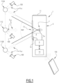
- Fig. 1 schematically illustrates a possible embodiment of a portable device 1 according to the invention, for receiving information transmitted by exploiting light signals emitted from at least one light source 100 to illuminate at least one object of interest to which the light source is associated and which is located inside an environment or exhibition space, in particular an internal or indoor environment.
- FIG. 2 schematically illustrates a system 200, of which the portable device 1 is part, for transmitting information within the exhibition environment in which one or more objects are arranged, each of which being illuminated by a corresponding light source 100.
- such an environment is schematically represented by a room of a museum where a picture 112 is displayed
- the environment 120 is schematically represented by a shop in which objects for sale, such as bags, shoes, watches, indicated by the reference number 114, are displayed.
- environment 120 are to be understood for illustrative and non-limiting purposes only, and the portable device 1 and the system 200 according to the invention are usable in any other environment suitable for the purposes of the present invention, as well as with any other type of objects arranged therein, such as environments in which there are, e.g., informative totems, various commercial, public or private premises of various nature, info points, etc..
- one or more light sources 100 are arranged within the environment 120, each of which is associated with at least one of the objects exposed therein and is configured to emit light signals to illuminate it.
- a single light source 100 is uniquely associated and illuminates the picture 112 exposed in the environment 120; in the example of Fig. 4 a single light source illuminates a group of objects 114 formed by shoes, bags, watches that are for example placed in a showcase or on a store shelf.
- each light source 100 is suitably driven by an electronic device, indicated in Fig. 2 by reference number 101, so that the light signals emitted by it convey the information to be transmitted to a user 130 who is observing for example the picture 112 of the example of Fig. 3 or the objects 114 exposed in the example of Fig. 4 .
- each control device 101 may be configured to pilot the or each light source 100 to emit, towards the object 112 or the objects 114, one or more light signals S VLC the intensity of which is modulated to transmit information.
- information is to be understood herein in the broadest possible sense, and such information may preferably contain data and/or contents of various kinds relating, for example to an observed object of interest, but also of a more general nature, relating, e.g., to the exhibition environment 120, etc.
- said one or more light sources 100 each comprise or consist of a corresponding modular light source, e.g., LED light source.
- said one or more light sources 100 each comprise or consist of a corresponding laser type source.
- the portable device 1 comprises a containment housing 3 provided with attachments means, schematically represented in Figures 3 and 4 by the reference numeral 5, which are configured to attach the portable device 1 to the body of a user 130, and in particular to a front part of the body when the user is visiting the environment or exhibition space 120.
- Such attachment means 5 may comprise for example, but not limited to, a band, a hook, a strap that allows to hang the device 1 around the neck of the user 130 as for instance illustrated in Fig. 3 , a pin, a clip that allows to hang the device 1 to the glasses of the user 130, as for example illustrated in Fig. 4 .
- the portable device 1 further comprises, arranged within the containment housing 3, an electronic control unit comprising a signal processor and schematically represented in Fig. 1 by the reference number 9, and an optical sensor, indicated by the reference number 7.
- the optical sensor 7 which preferably comprises or consists of, e.g., a photodiode, is configured to:
- This element associated with said object may be for example a surface or a reflective or light-diffusing panel, a part, e.g., the frame of the picture or a plate fixed to it, etc.
- the electronic unit 9 is configured to process the electrical signals S IN received in input from the optical sensor 7 and extract the information to be transmitted to the user 130 relating to the object of interest.
- the electronic unit 9 can be constituted by any processor device, e.g., of a commercially available type, suitably programmed and supplied to the extent necessary with circuitry, in order to perform the innovative functionalities conceived for the device 1 according to the present invention.
- a user 130 wearing the wearable device 1 when a user 130 wearing the wearable device 1 is in front of an object illuminated by the light source 100, for example when the user is observing the picture 112, said picture 112 and/or an element 113 associated with it, reflects or diffuses in the environment 120 and towards the user 130 at least a portion of the light projected by the light source 100.
- This reflected, projected, or diffused light is picked up by the optical sensor 7, which transduces it into electrical signals input to the electronic unit 9.
- the processor of the latter in turn appropriately processes the incoming received signals by extracting the transported information, relating for example to the exposed picture 112.
- the portable device 1 further comprises a communication module, schematically indicated in Fig. 1 by the reference numeral 10, which is operatively connected to the electronic unit 9 and is configured to transmit to a remote device 150, usable by the user 130, the information extracted by the signal processor.
- a communication module schematically indicated in Fig. 1 by the reference numeral 10, which is operatively connected to the electronic unit 9 and is configured to transmit to a remote device 150, usable by the user 130, the information extracted by the signal processor.
- the communication module 10 may be wired or wirelessly connected to the remote device 150, which may be for example a smartphone used by the user 130, as illustrated in the examples of Figures 3 and 4 .
- the extracted information may be conveyed to the user 130 without the smartphone 150 necessarily being held in hand, as for example illustrated in Fig. 3 where the smartphone 150 is shown stored in the bag of the visitor illustrated therein.
- the portable device 1 can be provided with a small display, schematically represented in Fig. 1 by the reference numeral 11, which is for example arranged on one of the walls of the containment housing 3 and is operatively connected to the communication module 10 for displaying the information received.
- a small display schematically represented in Fig. 1 by the reference numeral 11, which is for example arranged on one of the walls of the containment housing 3 and is operatively connected to the communication module 10 for displaying the information received.
- the portable device 1 further comprises configuration means for selectively modifying the field of view of said portable device 1.
- said configuration means are configured to be manually operable.
- said configuration means are configured to be automatically operable.
- the electronic unit 9 is configured to automatically operate said configuration means based on at least one or more of the information transmitted by means of the light signals S VLC emitted by the light source 100 and received by the receiving element 7.
- the electronic unit 9 is configured to automatically actuate the configuration means, e.g., based on one or more predefined parameters, such as for example but not limited to, pre-configured location maps on board the portable device 1, for example in a memory unit thereof, or on board a remote device, such as the same smartphone 150, or on another remote device operatively connectable to the portable device 1.
- predefined parameters such as for example but not limited to, pre-configured location maps on board the portable device 1, for example in a memory unit thereof, or on board a remote device, such as the same smartphone 150, or on another remote device operatively connectable to the portable device 1.
- the configuration means comprises a shutter or variable aperture diaphragm 13 arranged frontally and at a predetermined distance from the optical sensor 7 at an outer wall of the containment housing 3, as for example schematically illustrated in Fig. 1 .
- the electronic unit 9 can send a signal to a shutter operating device, schematically illustrated in Fig. 1 by the reference numeral 14.
- the optical sensor 7 is a photodiode with a diameter "L" of 10 mm
- the diaphragm 13 has a variable aperture with diameter "D” located at a distance "d” from the photodiode
- a visitor 130 in a room 120 of a museum in which the typical lateral separation between the works is 5m, with an observation distance from a work of about 5m, may be considered.
- the total angle of view (AoV) of the receiver shall be less than 90° to avoid interference with signals from light scattered from other nearby works.
- the maximum allowed AoV is therefore about 30°.
- the aperture D that allows to avoid interference with signals from contiguous objects is about 4mm.
- the information about the optimal aperture D is encoded in the light signals S VLC emitted from a light source 100 and can be extracted and used directly in automatic mode by the electronic unit 9 to vary the aperture of the shutter or diaphragm 13, or it can be transmitted to the user 130 who can manually intervene on the shutter itself.
- the choice of an angle of view or aperture for the receiver allows to avoid optical interference caused by signals from nearby "hotspots", i.e., the light sources 100 or objects close to the object of interest reflecting the light dedicated to them.
- the portable device 1 and the system 200 according to the invention make it possible to fulfil the intended purpose in that, by exploiting the technology of communication with visible light (“Visible Light Communication or VLC”) which has a very directional communication channel, a much lower latency and a much wider communication band than other wireless technologies based on radio waves, it allows to transmit the desired or useful information to users in an extremely simple, faster, targeted and effective way.
- visible light Visible Light Communication or VLC
- the information to be transmitted is encoded as digital information in the light emitted by the light sources 100, in such case the lighting lamps of objects acting as hotspots; each hotspot allows to create point-to-point connections between said hotspot and the wearable device 1 worn by a user, wherein the information conveyed from each hotspot may be different from that emitted from a neighboring hotspot, since the receiver (user) will receive only the signal contained in the light field emitted from a single source and reflected or diffused by the object it is observing and not from that from a neighboring hotspot.
- the receiving device is configured to be hung on a front part of the user's body allows the photo- receiving element 7 always to be substantially aligned with the point of view of the user himself, without this necessarily having to "point" a device manually towards the object of interest, thus receiving the information contained in the light used to illuminate and diffuse from the object of interest and/or the element associated with it in a completely natural way, allowing freedom of movement to the user.
- the user can be provided with information, dedicated and personal infotainment/augmented reality/advertising services, and it is also possible to create location protocols, in particular in indoor environments, where GPS location is ineffective, which allow the local network operator - be it a museum, a business activity, etc. - to have real-time information on how they are distributed and how users move within the area of interest.
- the portable device 1 can be suitably sized according to the applications, and in particular highly miniaturized if desired.
- optical sensor can be of any type suitable for the purpose, e.g., in one embodiment the optical sensor 7 can comprise or consist of a charge-coupled device or CCD, of any type of suitable light sensor, e.g. of the pixel type; a lens, positionable both in front of the shutter and between the shutter and the sensor, could also be arranged in front of the sensor, etc..
- CCD charge-coupled device
Landscapes
- Physics & Mathematics (AREA)
- Electromagnetism (AREA)
- Engineering & Computer Science (AREA)
- Computer Networks & Wireless Communication (AREA)
- Signal Processing (AREA)
- Optical Communication System (AREA)
Abstract
- a containment enclosure (3) provided with attachments means (5) suitable for attaching the portable device (1) to the body of a user (130) when visiting the environment (120); and, positioned within the containment enclosure (3):
- an optical sensor (7) configured to receive, when said user (130) is observing said object of interest (112, 114), at least a portion of the light signals (SVLC) received and reflected or diffused in the environment from at least one of said object of interest (112, 114) and an element (113) associated with said object of interest, and to emit corresponding electrical signals (SIN) indicative of said information contained in the light signals emitted by the light source (100);
- an electronic control unit (9) configured to process said electrical signals (SIN) received in input from the optical sensor (7) and extract from them said information to be transmitted to the user (130).
Description
- The present invention relates to a portable device for receiving information transmitted by means of light signals and related to objects arranged within an exhibition environment or space, and an information transmitting system using such a portable device.
- The portable device and the information transmission system according to the invention are particularly suitable for use in indoor environments, i.e., in substantially enclosed indoor environments, such as, for example, museums, shops, shopping centers, and will be described with specific reference to these areas without intending in any way to limit their possible application to other types of environments or spaces in which there may be objects of interest illuminated by one or more sources and of which a user may wish to receive information.
- As is well-known, in recent decades the continuous development and diffusion of increasingly powerful and high-performance technologies and means of communication has made it possible to enrich the quality and quantity of services offered, for example to visitors of museums, art galleries, exhibition spaces, commercial spaces, etc.
- For example, in museums, next to traditional audio guides, visitors can use their smartphones to access additional digital services, for example about the works they are observing, to download multimedia content in real time, to enjoy interactive applications in augmented reality, etc.
- Although these solutions allow to offer a qualitatively adequate level of digital services, they still have some drawbacks that can be improved.
- For example, wireless technologies based on radio waves, in which "local" networks are created within the environment through various "hotspots" arranged along a path, are usually used to access these services.
- These local networks involve the use of complex handshaking protocols for the projection of the user in the network, typical of RF technologies, and usually have a remarkably high latency in the connection step, which in fact results in making too long the process of passing and docking to the contiguous hotspots.
- In this way, the use of the services offered can be somewhat difficult if the user moves within an environment in which the various hotspots are arranged along the path.
- Moreover, the theoretical band that can be obtained with such RF technologies is still relatively small.
- In more recent solutions, the camera or the optical sensor integrated in a smartphone can be used directly to access the services offered.
- In this case, however, it is necessary to continuously use the own smartphone, for example by keeping it pointed towards the object under observation.
- This can clearly cause some discomfort for the users, who may have to assume unnatural positions that affect the visual experience and the use of digital content through their phone, for example to keep the camera or the optical sensor of their phone in the most correct position.
- Therefore, the object of the present invention is to obviate, at least partially, one or more of the aforementioned drawbacks, and in particular to offer a solution that allows users to enjoy the digital services offered during the visit in indoor or outdoor exhibition environments, such as, e.g., museums, shops, commercial spaces etc., in a simplified and more effective way than the currently known solutions.
- This object is achieved by a portable device whose features are defined in claim 1.
- This object is further achieved by a system for transmitting information within an indoor environment according to
claim 13. - Particular embodiments are the subject of the dependent claims, the content of which is to be understood as an integral part of the present description.
- Further characteristics and advantages of the invention will appear from the following detailed description, made by way of a non-limiting example, with reference to the attached drawings, in which:
-
Fig. 1 is a view schematically illustrating a section of a device in accordance with the invention, which is usable within an environment in which there is an object of interest; -
Fig. 2 is a block diagram schematically illustrating a system according to the invention, used within an exhibition environment and including the portable device ofFig. 1 ; -
Fig. 3 schematically illustrates a visitor equipped with the portable device according to the invention during a visit in a museum environment; -
Fig. 4 schematically illustrates a visitor equipped with the portable device according to the invention during a visit in a commercial environment, such as a shop. - It should be noted that in the following detailed description, identical or similar components, from a structural and/or functional point of view, may have the same or different reference numbers, regardless of whether they are shown in different embodiments of the present invention or in distinct parts.
- It should also be noted that, in order to clearly and concisely describe the present invention, the drawings may not necessarily be to scale, and certain features of the description may be shown in somewhat schematic form.
- In addition, where the term "adapted" or "configured" or "shaped", or a similar term is used herein with respect to any component as a whole, or any part of a component, it is to be understood as correspondingly comprising the structure and/or configuration and/or shape and/or positioning of the component or part to which it relates.
- In particular, when such terms refer to hardware or software electronic means, they are to be understood as including electronic circuits or circuit parts, as well as software/firmware, such as for example algorithms, routines and programs in general, running and/or residing on any storage medium.
-
Fig. 1 schematically illustrates a possible embodiment of a portable device 1 according to the invention, for receiving information transmitted by exploiting light signals emitted from at least onelight source 100 to illuminate at least one object of interest to which the light source is associated and which is located inside an environment or exhibition space, in particular an internal or indoor environment. - In turn,
Fig. 2 schematically illustrates asystem 200, of which the portable device 1 is part, for transmitting information within the exhibition environment in which one or more objects are arranged, each of which being illuminated by acorresponding light source 100. - In particular, in the illustrative example of
Fig. 3 , such an environment, indicated by thereference number 120, is schematically represented by a room of a museum where apicture 112 is displayed, while in the illustrative example ofFig. 4 theenvironment 120 is schematically represented by a shop in which objects for sale, such as bags, shoes, watches, indicated by thereference number 114, are displayed. - Clearly, such examples of
environment 120 are to be understood for illustrative and non-limiting purposes only, and the portable device 1 and thesystem 200 according to the invention are usable in any other environment suitable for the purposes of the present invention, as well as with any other type of objects arranged therein, such as environments in which there are, e.g., informative totems, various commercial, public or private premises of various nature, info points, etc.. - Depending on the specific applications, one or more
light sources 100 are arranged within theenvironment 120, each of which is associated with at least one of the objects exposed therein and is configured to emit light signals to illuminate it. - In the example of
Fig. 3 , asingle light source 100 is uniquely associated and illuminates thepicture 112 exposed in theenvironment 120; in the example ofFig. 4 a single light source illuminates a group ofobjects 114 formed by shoes, bags, watches that are for example placed in a showcase or on a store shelf. - According to embodiments known or easily achievable by a person skilled in the art, each
light source 100 is suitably driven by an electronic device, indicated inFig. 2 byreference number 101, so that the light signals emitted by it convey the information to be transmitted to auser 130 who is observing for example thepicture 112 of the example ofFig. 3 or theobjects 114 exposed in the example ofFig. 4 . - In particular, there may be a
single control device 101 formultiple light sources 100, or eachlight source 100 may be associated with asingle control device 101, as illustrated in the example ofFigure 2 ; the or eachcontrol device 101 is configured to pilot the or eachlight source 100 to emit, towards theobject 112 or theobjects 114, one or more light signals SVLC the intensity of which is modulated to transmit information. - The term "information" is to be understood herein in the broadest possible sense, and such information may preferably contain data and/or contents of various kinds relating, for example to an observed object of interest, but also of a more general nature, relating, e.g., to the
exhibition environment 120, etc. - Conveniently, in the portable device 1 and in the
system 200 according to the invention, said one ormore light sources 100 each comprise or consist of a corresponding modular light source, e.g., LED light source. - Alternatively, said one or
more light sources 100 each comprise or consist of a corresponding laser type source. - As illustrated in
Figure 1 , the portable device 1 comprises acontainment housing 3 provided with attachments means, schematically represented inFigures 3 and4 by thereference numeral 5, which are configured to attach the portable device 1 to the body of auser 130, and in particular to a front part of the body when the user is visiting the environment orexhibition space 120. - Such attachment means 5 may comprise for example, but not limited to, a band, a hook, a strap that allows to hang the device 1 around the neck of the
user 130 as for instance illustrated inFig. 3 , a pin, a clip that allows to hang the device 1 to the glasses of theuser 130, as for example illustrated inFig. 4 . - Usefully, the portable device 1 according to the invention further comprises, arranged within the
containment housing 3, an electronic control unit comprising a signal processor and schematically represented inFig. 1 by thereference number 9, and an optical sensor, indicated by thereference number 7. - In particular, the
optical sensor 7, which preferably comprises or consists of, e.g., a photodiode, is configured to: - receive, when the
user 130 faces and is observing anobject environment 120 by said illuminated object or by an element that is associated with the object itself, i.e. arranged contiguous with it, and that is also adapted to diffuse or reflect the light signals SVLC; and - emit as input to the
electronic control unit 9, and in particular to its signal processor, corresponding electrical signals SIN indicative of the information carried by the received light signals. - This element associated with said object, schematically represented for simplicity only in
Fig. 3 and indicated therein withreference number 113, may be for example a surface or a reflective or light-diffusing panel, a part, e.g., the frame of the picture or a plate fixed to it, etc. In turn, theelectronic unit 9 is configured to process the electrical signals SIN received in input from theoptical sensor 7 and extract the information to be transmitted to theuser 130 relating to the object of interest. - The
electronic unit 9 can be constituted by any processor device, e.g., of a commercially available type, suitably programmed and supplied to the extent necessary with circuitry, in order to perform the innovative functionalities conceived for the device 1 according to the present invention. - In practice, when a
user 130 wearing the wearable device 1 is in front of an object illuminated by thelight source 100, for example when the user is observing thepicture 112, saidpicture 112 and/or anelement 113 associated with it, reflects or diffuses in theenvironment 120 and towards theuser 130 at least a portion of the light projected by thelight source 100. This reflected, projected, or diffused light is picked up by theoptical sensor 7, which transduces it into electrical signals input to theelectronic unit 9. The processor of the latter in turn appropriately processes the incoming received signals by extracting the transported information, relating for example to the exposedpicture 112. - Suitably, the portable device 1 further comprises a communication module, schematically indicated in
Fig. 1 by thereference numeral 10, which is operatively connected to theelectronic unit 9 and is configured to transmit to aremote device 150, usable by theuser 130, the information extracted by the signal processor. - The
communication module 10 may be wired or wirelessly connected to theremote device 150, which may be for example a smartphone used by theuser 130, as illustrated in the examples ofFigures 3 and4 . - The extracted information may be conveyed to the
user 130 without thesmartphone 150 necessarily being held in hand, as for example illustrated inFig. 3 where thesmartphone 150 is shown stored in the bag of the visitor illustrated therein. - In a possible embodiment, optionally the portable device 1 can be provided with a small display, schematically represented in
Fig. 1 by thereference numeral 11, which is for example arranged on one of the walls of thecontainment housing 3 and is operatively connected to thecommunication module 10 for displaying the information received. - Advantageously, the portable device 1 according to the invention further comprises configuration means for selectively modifying the field of view of said portable device 1. According to a possible embodiment said configuration means are configured to be manually operable.
- According to a further possible embodiment said configuration means are configured to be automatically operable.
- In particular, according to a first variant, the
electronic unit 9 is configured to automatically operate said configuration means based on at least one or more of the information transmitted by means of the light signals SVLC emitted by thelight source 100 and received by thereceiving element 7. - In addition or alternatively to said first variant, the
electronic unit 9 is configured to automatically actuate the configuration means, e.g., based on one or more predefined parameters, such as for example but not limited to, pre-configured location maps on board the portable device 1, for example in a memory unit thereof, or on board a remote device, such as thesame smartphone 150, or on another remote device operatively connectable to the portable device 1. - In a possible embodiment, the configuration means comprises a shutter or
variable aperture diaphragm 13 arranged frontally and at a predetermined distance from theoptical sensor 7 at an outer wall of thecontainment housing 3, as for example schematically illustrated inFig. 1 . - In the case of manual operation, for example the user can act directly on the shutter or
diaphragm 13 by varying the opening as a function of the information received; alternatively, in the case of automatic operation, theelectronic unit 9 can send a signal to a shutter operating device, schematically illustrated inFig. 1 by thereference numeral 14. - For example, with reference to
Fig. 1 , assuming that theoptical sensor 7 is a photodiode with a diameter "L" of 10 mm, and that thediaphragm 13 has a variable aperture with diameter "D" located at a distance "d" from the photodiode, the angle of view ("Angle of View"- AoV) determines the value of the diameter D through the relationship D=2d*tan(AoV) - L. - In a first example, a
visitor 130 in aroom 120 of a museum in which the typical lateral separation between the works is 5m, with an observation distance from a work of about 5m, may be considered. - In this case, the total angle of view (AoV) of the receiver shall be less than 90° to avoid interference with signals from light scattered from other nearby works.
- This angle is obtained by selecting an aperture D = approximately 19 mm.
- In the case of a showcase with illuminated objects separated by 50 cm and a typical observation distance of about 2 m, the maximum allowed AoV is therefore about 30°.
- In this case, the aperture D that allows to avoid interference with signals from contiguous objects is about 4mm.
- In such cases, the information about the optimal aperture D is encoded in the light signals SVLC emitted from a
light source 100 and can be extracted and used directly in automatic mode by theelectronic unit 9 to vary the aperture of the shutter ordiaphragm 13, or it can be transmitted to theuser 130 who can manually intervene on the shutter itself. - In this way, the choice of an angle of view or aperture for the receiver, adapted to each specific use case, allows to avoid optical interference caused by signals from nearby "hotspots", i.e., the
light sources 100 or objects close to the object of interest reflecting the light dedicated to them. - It has been observed in practice that the portable device 1 and the
system 200 according to the invention make it possible to fulfil the intended purpose in that, by exploiting the technology of communication with visible light ("Visible Light Communication or VLC") which has a very directional communication channel, a much lower latency and a much wider communication band than other wireless technologies based on radio waves, it allows to transmit the desired or useful information to users in an extremely simple, faster, targeted and effective way. - In particular, as previously described, the information to be transmitted is encoded as digital information in the light emitted by the
light sources 100, in such case the lighting lamps of objects acting as hotspots; each hotspot allows to create point-to-point connections between said hotspot and the wearable device 1 worn by a user, wherein the information conveyed from each hotspot may be different from that emitted from a neighboring hotspot, since the receiver (user) will receive only the signal contained in the light field emitted from a single source and reflected or diffused by the object it is observing and not from that from a neighboring hotspot. - The fact that the receiving device is configured to be hung on a front part of the user's body allows the photo- receiving
element 7 always to be substantially aligned with the point of view of the user himself, without this necessarily having to "point" a device manually towards the object of interest, thus receiving the information contained in the light used to illuminate and diffuse from the object of interest and/or the element associated with it in a completely natural way, allowing freedom of movement to the user. - In addition, the user can be provided with information, dedicated and personal infotainment/augmented reality/advertising services, and it is also possible to create location protocols, in particular in indoor environments, where GPS location is ineffective, which allow the local network operator - be it a museum, a business activity, etc. - to have real-time information on how they are distributed and how users move within the area of interest.
- To achieve this, components of easy and low-cost realization and assembly are used, being based on consumer electronics; moreover, the portable device 1 can be suitably sized according to the applications, and in particular highly miniaturized if desired.
- Moreover, by equipping the user with such a device 1, e.g., at the entrance to a museum or a store can contribute to the attractiveness of the museum/store itself in terms of "technological curiosity", since the user will in practice feel more enticed to take advantage of digital services precisely because of having an additional "intelligent" physical device on him/her.
- Of course, the principle of the invention remaining the same, the embodiments and the details of embodiment can be varied widely from what has been described and illustrated purely by way of preferred but non-limiting examples, without departing from the scope of protection of the present invention as defined in particular by the attached claims. For example, in addition to those described above, other suitable supports may be used to hook the device 1 to any front part of the user's
body 130. The optical sensor can be of any type suitable for the purpose, e.g., in one embodiment theoptical sensor 7 can comprise or consist of a charge-coupled device or CCD, of any type of suitable light sensor, e.g. of the pixel type; a lens, positionable both in front of the shutter and between the shutter and the sensor, could also be arranged in front of the sensor, etc..
Claims (15)
- Portable device (1) for receiving information transmitted by means of light signals (SVLC) emitted from at least one light source (100) for illuminating at least one object of interest (112, 114) disposed within an environment (120), characterized in that it comprises at least:- a containment enclosure (3) provided with attachments means (5) suitable for attaching the portable device (1) to the body of a user (130) when visiting the environment (120); and, positioned within the containment enclosure (3):- an optical sensor (7) configured to receive, when said user (130) is observing said object of interest (112, 114), at least a portion of the light signals (SVLC) received and reflected or diffused in the environment from at least one of said object of interest (112, 114) and an element (113) associated with said object of interest, and to emit corresponding electrical signals (SIN) indicative of said information contained in the light signals emitted by the light source (100);- an electronic control unit (9) configured to process said electrical signals (SIN) received in input from the optical sensor (7) and extract from them said information to be transmitted to the user (130).
- Portable device (1) according to claim 1, further comprising communication means (10) operatively connected to said electronic control unit (9) and configured to transmit to a remote device (150) usable by the user (130) the information extracted from the electronic control unit (9).
- Portable device (1) according to claim 1 or 2, further comprising configuration means (13, 14) for selectively changing the field of view of the device (1).
- Portable device (1) according to claim 3, wherein said configuration means are configured to be operated manually.
- Portable device (1) according to claim 3, wherein said configuration means are configured to transmit be operated automatically.
- Portable device (1) according to claim 5, wherein said electronic control unit (9) is configured to automatically operate said configuration means (13, 14) based on at least one or more of the information transmitted by means of the light signals (SVLC) emitted by the light source (100).
- Portable device (1) according to claim 5 or 6, wherein said electronic control unit (9) is configured to automatically operate said configuration means based on pre-configured location maps stored on board the portable device (1) or on board a remote device (150) operatively connectable to the portable device (1).
- Portable device (1) according to claim 3, wherein said configuration means comprise a variable aperture diaphragm or shutter (13) positioned in front and at a predetermined distance from said optical sensor (7) at an outer wall of the containment housing (3).
- Portable device (1) according to claim 3, wherein said configuration means further comprise an actuating device (14) configured to actuate said diaphragm or shutter (13) and operatively enslaved to the electronic control unit (9).
- Portable device (1) according to one or more of the preceding claims, comprising a display (11) for displaying the received information.
- Portable device (1) according to one or more of the preceding claims, wherein said optical sensor (7) comprises a photodiode.
- Portable device (1) according to one or more of the preceding claims, wherein said attachments means (5) are selected from the group comprising a pin, a strap, a clip, a hook, a band.
- A system (200) for transmitting information within an environment (120) in which there are positioned one or more objects of interest (112, 114), characterized in that it comprises:- one or more light sources (100) placed within the environment (120), each of said one or more light sources (100) being associated with and configured to emit light signals (SVLC) capable to illuminate at least one object of interest (112, 114) and carrying information intended to be transmitted to at least one user (130) when visiting the environment (120); and- at least one portable device (1) according to one or more of the preceding claims, suitable for being bound to the body of said user (130) for receiving the information carried by said light signals (SVLC).
- System (200) according to claim 13, wherein said one or more light sources (100) comprise or consist of an LED light source.
- System (200) according to claim 13, wherein said one or more light sources (100) comprise or consist of a laser light source.
Applications Claiming Priority (1)
| Application Number | Priority Date | Filing Date | Title |
|---|---|---|---|
| IT102022000007529A IT202200007529A1 (en) | 2022-04-14 | 2022-04-14 | Portable device for receiving information transmitted by light signals and relating to objects arranged within an exhibition environment, and information transmission system using such a device |
Publications (1)
| Publication Number | Publication Date |
|---|---|
| EP4262107A1 true EP4262107A1 (en) | 2023-10-18 |
Family
ID=82385480
Family Applications (1)
| Application Number | Title | Priority Date | Filing Date |
|---|---|---|---|
| EP23167781.6A Pending EP4262107A1 (en) | 2022-04-14 | 2023-04-13 | Portable device for receiving information transmitted by means of light signals and related to objects placed within an exhibition environment, and information transmission system using such device |
Country Status (2)
| Country | Link |
|---|---|
| EP (1) | EP4262107A1 (en) |
| IT (1) | IT202200007529A1 (en) |
Citations (5)
| Publication number | Priority date | Publication date | Assignee | Title |
|---|---|---|---|---|
| US20110031160A1 (en) * | 2009-08-05 | 2011-02-10 | Theresa Wright Leggett | Neck cell |
| US20120080469A1 (en) * | 2010-10-04 | 2012-04-05 | Souders Roger B | Apparatus for carrying hand-held wireless electronic device |
| WO2015115717A1 (en) * | 2014-01-28 | 2015-08-06 | ㈜유양디앤유 | Device and method for providing service by using visible light communication and terminal therefor |
| US20170307382A1 (en) * | 2014-09-15 | 2017-10-26 | Yuyang Dnu Co., Ltd. | Route guidance method and device for audience in exhibition hall by means of visible light communication |
| KR20180035552A (en) * | 2016-09-29 | 2018-04-06 | 한국광기술원 | object color independence camera communication system and method thereof |
-
2022
- 2022-04-14 IT IT102022000007529A patent/IT202200007529A1/en unknown
-
2023
- 2023-04-13 EP EP23167781.6A patent/EP4262107A1/en active Pending
Patent Citations (5)
| Publication number | Priority date | Publication date | Assignee | Title |
|---|---|---|---|---|
| US20110031160A1 (en) * | 2009-08-05 | 2011-02-10 | Theresa Wright Leggett | Neck cell |
| US20120080469A1 (en) * | 2010-10-04 | 2012-04-05 | Souders Roger B | Apparatus for carrying hand-held wireless electronic device |
| WO2015115717A1 (en) * | 2014-01-28 | 2015-08-06 | ㈜유양디앤유 | Device and method for providing service by using visible light communication and terminal therefor |
| US20170307382A1 (en) * | 2014-09-15 | 2017-10-26 | Yuyang Dnu Co., Ltd. | Route guidance method and device for audience in exhibition hall by means of visible light communication |
| KR20180035552A (en) * | 2016-09-29 | 2018-04-06 | 한국광기술원 | object color independence camera communication system and method thereof |
Non-Patent Citations (1)
| Title |
|---|
| ALBRAHEEM LAMYA I ET AL: "Toward Designing a Li-Fi-Based Hierarchical IoT Architecture", IEEE ACCESS, vol. 6, 2018, pages 40811 - 40825, XP011688429, DOI: 10.1109/ACCESS.2018.2857627 * |
Also Published As
| Publication number | Publication date |
|---|---|
| IT202200007529A1 (en) | 2023-10-14 |
Similar Documents
| Publication | Publication Date | Title |
|---|---|---|
| US9584641B2 (en) | Messaging device | |
| ES2668904T3 (en) | Information communication procedure | |
| JP6345697B2 (en) | Information processing program, reception program, and information processing apparatus | |
| US9483875B2 (en) | Augmented reality system with encoding beacons | |
| JP5683737B1 (en) | Control method, information communication apparatus, and program | |
| JP6378511B2 (en) | Information communication method, information communication apparatus, and program | |
| WO2014103161A1 (en) | Information communication method | |
| EP1184704A2 (en) | Communication terminal device and lens adaptor | |
| US20110001935A1 (en) | Digital image projection system | |
| US20170052561A1 (en) | Multifunctional Wearable with Live Cam | |
| JP6970146B2 (en) | Programs, control methods, and information and communication equipment | |
| JP2018032885A (en) | Information processing program, receiving program, and information processing device | |
| WO2014103154A1 (en) | Information communication method | |
| US20210182011A1 (en) | Lighting apparatus | |
| US20180094937A1 (en) | Interactive glasses and navigation system | |
| JP2018032884A (en) | Receiving program and receiving apparatus | |
| JP6849773B2 (en) | Programs, control methods and controls | |
| JP2006092463A (en) | Call management system and call management method | |
| JP2007135144A (en) | Visible light communication receiver | |
| KR101541012B1 (en) | Image making and transmission device using Digital Information Display and method thereof | |
| JP6944571B2 (en) | Programs, devices and control methods | |
| KR20170133710A (en) | System and method for visible light communication using smartphone | |
| WO2016194209A1 (en) | Image pickup system | |
| JP2012005110A (en) | Mirror stand with imaging apparatus to be controlled remotely | |
| CN118887890A (en) | Brightness adjustment method, system, device, terminal and readable storage medium |
Legal Events
| Date | Code | Title | Description |
|---|---|---|---|
| PUAI | Public reference made under article 153(3) epc to a published international application that has entered the european phase |
Free format text: ORIGINAL CODE: 0009012 |
|
| STAA | Information on the status of an ep patent application or granted ep patent |
Free format text: STATUS: THE APPLICATION HAS BEEN PUBLISHED |
|
| AK | Designated contracting states |
Kind code of ref document: A1 Designated state(s): AL AT BE BG CH CY CZ DE DK EE ES FI FR GB GR HR HU IE IS IT LI LT LU LV MC ME MK MT NL NO PL PT RO RS SE SI SK SM TR |
|
| STAA | Information on the status of an ep patent application or granted ep patent |
Free format text: STATUS: REQUEST FOR EXAMINATION WAS MADE |
|
| 17P | Request for examination filed |
Effective date: 20240307 |
|
| RBV | Designated contracting states (corrected) |
Designated state(s): AL AT BE BG CH CY CZ DE DK EE ES FI FR GB GR HR HU IE IS IT LI LT LU LV MC ME MK MT NL NO PL PT RO RS SE SI SK SM TR |
|
| STAA | Information on the status of an ep patent application or granted ep patent |
Free format text: STATUS: EXAMINATION IS IN PROGRESS |
|
| 17Q | First examination report despatched |
Effective date: 20241206 |