EP4262027A1 - Connector assembly - Google Patents
Connector assembly Download PDFInfo
- Publication number
- EP4262027A1 EP4262027A1 EP22167638.0A EP22167638A EP4262027A1 EP 4262027 A1 EP4262027 A1 EP 4262027A1 EP 22167638 A EP22167638 A EP 22167638A EP 4262027 A1 EP4262027 A1 EP 4262027A1
- Authority
- EP
- European Patent Office
- Prior art keywords
- cavity
- tool
- connector assembly
- signal contact
- inner signal
- Prior art date
- Legal status (The legal status is an assumption and is not a legal conclusion. Google has not performed a legal analysis and makes no representation as to the accuracy of the status listed.)
- Pending
Links
Images


Classifications
-
- H—ELECTRICITY
- H01—ELECTRIC ELEMENTS
- H01R—ELECTRICALLY-CONDUCTIVE CONNECTIONS; STRUCTURAL ASSOCIATIONS OF A PLURALITY OF MUTUALLY-INSULATED ELECTRICAL CONNECTING ELEMENTS; COUPLING DEVICES; CURRENT COLLECTORS
- H01R13/00—Details of coupling devices of the kinds covered by groups H01R12/70 or H01R24/00 - H01R33/00
- H01R13/40—Securing contact members in or to a base or case; Insulating of contact members
- H01R13/42—Securing in a demountable manner
-
- H—ELECTRICITY
- H01—ELECTRIC ELEMENTS
- H01R—ELECTRICALLY-CONDUCTIVE CONNECTIONS; STRUCTURAL ASSOCIATIONS OF A PLURALITY OF MUTUALLY-INSULATED ELECTRICAL CONNECTING ELEMENTS; COUPLING DEVICES; CURRENT COLLECTORS
- H01R13/00—Details of coupling devices of the kinds covered by groups H01R12/70 or H01R24/00 - H01R33/00
- H01R13/40—Securing contact members in or to a base or case; Insulating of contact members
- H01R13/42—Securing in a demountable manner
- H01R13/422—Securing in resilient one-piece base or case, e.g. by friction; One-piece base or case formed with resilient locking means
- H01R13/4223—Securing in resilient one-piece base or case, e.g. by friction; One-piece base or case formed with resilient locking means comprising integral flexible contact retaining fingers
-
- H—ELECTRICITY
- H01—ELECTRIC ELEMENTS
- H01R—ELECTRICALLY-CONDUCTIVE CONNECTIONS; STRUCTURAL ASSOCIATIONS OF A PLURALITY OF MUTUALLY-INSULATED ELECTRICAL CONNECTING ELEMENTS; COUPLING DEVICES; CURRENT COLLECTORS
- H01R43/00—Apparatus or processes specially adapted for manufacturing, assembling, maintaining, or repairing of line connectors or current collectors or for joining electric conductors
- H01R43/20—Apparatus or processes specially adapted for manufacturing, assembling, maintaining, or repairing of line connectors or current collectors or for joining electric conductors for assembling or disassembling contact members with insulating base, case or sleeve
- H01R43/22—Hand tools
Definitions
- the present disclosure relates to a connector assembly, preferably for multi GHz applications.
- the disclosure relates to an H-MTD ® (High Speed Modular Twisted-Pair-Data) connector assembly.
- H-MTD ® High Speed Modular Twisted-Pair-Data
- H-MTD ® system has been established by a company called "Rosenberger Hochfrequenztechnik GmbH & Co. KG".
- Applications for the H-MTD ® system are 4K camera systems, autonomous driving, radar, lidar, high-resolution displays and rear seat entertainment. Connectors of said system are meant to allow data transmission up to 15 GHz or 20 Gbps while having a small package size.
- an inner signal contact is secured in an insulating element by means of a locking mechanism.
- the locking mechanism can be accessed via a cavity located at a side of the insulating element with a standard tool such as a slotted screwdriver so as to unlock the locking mechanism and, thereby, allow the inner signal contact to be separated from the insulating element.
- the connector assembly may be of a multi-cavity kind comprising multiple inner signal contacts mounted side-by-side in the insulating element.
- the connector assembly may be mounted into another device, such that the insulating element is only accessible from a front-side thereof. In both cases, accessing a cavity provided on a side of the insulating element may be troublesome or even not possible.
- operating the locking mechanism by executing an unguided movement with a standard tool, such as a screwdriver, bears the risk that the locking mechanism may be damaged or break.
- the present disclosure is directed at a connector assembly comprising an elongated inner signal contact and an insulating element.
- the insulating element includes a first cavity configured to accommodate the inner signal contact, a latching element configured to secure the inner signal contact in the first cavity, and an elongated second cavity extending in an axial direction and configured to receive a tool for separating the latching element from the inner signal contact.
- the first cavity and the second cavity may be separated by the latching element.
- the latching element may comprise a protrusion extending into the first cavity, which is configured to interact with a latching shoulder of the inner signal contact when the inner signal contact is accommodated in the first cavity.
- the protrusion serves as a securing means for securing the inner signal contact in the first cavity.
- the latching element may also comprise a hook section defining an end portion of the second cavity, wherein the hook section is configured to receive an end of an insertion portion of the tool.
- the insulating element may define a pivot bearing for the tool.
- a pivot axis defined by the pivot bearing may be perpendicular to the axial direction.
- the pivot bearing may be positioned at an axial distance from the hook section.
- the tool when the tool is fully inserted into second cavity, the tool can be pivoted around the pivot axis so as to disengage the protrusion of the latching element from the inner signal contact to thereby allow removal of the inner signal contact from the first cavity.
- the first cavity and the second cavity may extend substantially parallel to each other.
- the second cavity does not need to be inserted from a lateral side of the insulating element which may be cumbersome or even impossible. Instead, it can be inserted from a front side of the insulating element which is usually easily accessible.
- the first cavity and the second cavity may be configured to allow for insertion of the inner signal contact and the tool from opposite sides of the insulating element.
- the tool can be inserted via a front side of the insulating element while the inner signal contact is removed via a back side of the insulating element.
- the present disclosure is directed at a connector system comprising a connector assembly of the kind described above and the aforementioned tool.
- the tool may comprise a handle and an insertion portion.
- the tool may comprise a pivot means formed between the handle and the insertion portion.
- the pivot means may be configured to interact with a pivot bearing defined by the insulating element.
- Fig. 1A depicts a perspective view onto a front side of an insulating element 16 of a connector assembly 10.
- the connector assembly 10 may be an H-MTD ® (High Speed Modular Twisted-Pair-Data) connector assembly.
- the insulating element 16 serves as a di-electric housing and defines an elongated first cavity 18 for accommodating an inner signal contact 12, as shown in Fig. 2 .
- the first cavity 18 has a first opening 20 at a front side of the insulating element 16 and a second opening 22 at a back side of the insulating element 16.
- a connection portion of the inner signal contact 12 accommodated in the first cavity 18 can be accessed, e.g. by a mating electrical connector, whereas via the second opening 22 of the insulating element 16, the inner signal contact 12 can be inserted into the first cavity 18.
- the insulating element 16 also defines a second cavity 24 associated with the first cavity 18.
- the second cavity 24 extends in an axial direction (the Y-direction in the drawings) and substantially parallel to the first cavity 18.
- the second cavity 24 further has an entry opening 48 at the front side of the insulating element 16 via which a dedicated tool 38 described in more detail below can be inserted ( Fig. 1B and 3B ).
- the first cavity 18 and the second cavity 24 are configured to allow for insertion of the inner signal contact 12 and the tool 38 from opposite sides of the insulating element 16.
- a cross-sectional area of the second cavity 24 is dimensioned so as to allow for a lever movement of the tool 38. More specifically, there is a clearance 54 between a boundary wall of the second cavity 24 and an insertion portion 44 of the tool 38 when the tool 38 is fully inserted into the second cavity 24.
- the first cavity 18 and the second cavity 24 share a common wall portion that serves as a latching element 26.
- the latching element 26 comprises a protrusion 28 that extends into the first cavity 18. As depicted in Fig. 2 , when the inner signal contact 12 is correctly positioned in the first cavity 18, the protrusion 28 engages behind a latching shoulder 14 of the inner signal contact 12, thereby securing the inner signal contact 12 in the first cavity 18 against an unintended movement out of the first cavity 18.
- the latching element 26 further comprises a hook section 30 which defines an end portion of the second cavity 24.
- the hook section 30 extends in a direction opposite from the protrusion 28 and is configured to receive a leading end 46 of an insertion portion 44 of the tool 38 ( Fig. 3B ).
- An end region of the hook section 30 may feature the shape of a wedge so as to facilitate insertion of the tool 38 into the hook section 30.
- the insulating element 16 further defines a pivot bearing 32 adapted to cooperate with the tool 38. More specifically, as can be seen in Fig. 3A , the pivot bearing 32 comprises two neighboring surface portions, a first surface portion 34 on a left side of the second cavity 24, and a corresponding second surface portion 36 on a right side of the second cavity 24 as viewed in the axial direction. Said first and second surface portions extend in a plane generally perpendicular to the axial direction, i.e. in a plane defined by the vertical direction Z and the horizontal direction X in Figs. 3A and 3B , and are located at the same height with respect to the vertical direction.
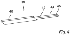
- Fig. 4 is a perspective view of the tool 38 for separating the latching element 26 from the inner signal contact 12.
- the tool 38 comprises a handle 40, a pivot means 42 and an insertion portion 44.
- the pivot means 42 is formed between the handle 40 and the insertion portion 44 and comprises two lateral pins 42 extending in opposite directions from a main body of the tool 38.
- the insertion portion 44 has an elongated shape and a leading end 46 of the insertion portion 44 is configured to be received in the hook section 30 of the latching element 26.
- a rear end of the insertion portion 44 is defined by the lateral pins 42.
- the handle 40 may feature an outer cross-sectional dimension larger than that of the insertion portion 44 so as to allow for convenient handling by a user.
- the lateral pins 42 may have rounded edges to facilitate a lever movement of the tool 38.
- the pivot bearing 32 and the hook section 30 are separated by a predetermined distance 50 in the axial direction. More specifically, a distance 50 between the pivot bearing 32 and the end surface 52 of the second cavity 24 defined by the inner surface of the hook section 30 generally corresponds to the length of the insertion portion 44 of the tool 38.
- the tool 38 can be rotated about a pivot axis generally perpendicular to the axial direction when the tool 38 is fully inserted into the second cavity 24, i.e. when the pivot means 42 is in contact with the pivot bearing 32 and the leading end 46 of the insertion portion 44 is received in the hook section 30. More specifically, the pivot axis is located at the interface between the lateral pins 42 and the first and second surface portions. Due to the clearance 54 between the second cavity 24 and the insertion portion 44, the tool 38 can perform a lever movement during which the latching element 26 is bent in the vertical direction Z, i.e. in a direction away from the first cavity 18 and into the second cavity 24. Consequently, the protrusion 28 of the latching element 26 is disengaged from the latching shoulder 14 of the inner signal contact 12, and the inner signal contact 12 can be removed from the insulating element 16.
- the displacement of the leading end 46 of the insertion portion 44 in the vertical direction is limited by the second cavity 24 and thereby defines a maximum displacement of the latching element 26 from a locking position to a release position.
- the release position is reached, further displacement of the insertion portion 44 is blocked by a boundary wall of the second cavity 24, i.e. the latching element 26 can only bent as far as necessary for unlatching the inner signal contact 12.
- the width of the second cavity 24 in the horizontal direction X substantially corresponds to the width of the insertion portion 44 of the tool 38, and the pivot bearing 32 and the pivot means 42 come into contact as soon as the end position of the tool 38 inserted into the second cavity 24 is reached.
- an insertion movement of the tool 38 into the second cavity 24 along the axial direction is well guided and restricted. Therefore, not only the tool 38 can easily be inserted into the second cavity 24, but also no excessive force can be exerted in the axial direction on the hook section 30 of the latching element 26, both helping to prevent any damage to or breaking of the latching element 26.
- the insulating element 16 may define not only one first cavity 18 and one second cavity 24, but a plurality of first cavities 18 and, correspondingly, a plurality of respective second cavities 24.
- the entry opening of the second cavity 24 may be located at the back side of the insulating element 16, rather than at the front side of the insulating element 16. It is even conceivable, that the entry opening of the second cavity 24 is located at a side of the insulating element 16 other than the front and back sides, in which case the second cavity 24 would extend transversely to the first cavity 18.
Landscapes
- Engineering & Computer Science (AREA)
- Manufacturing & Machinery (AREA)
- Details Of Connecting Devices For Male And Female Coupling (AREA)
Abstract
Description
- The present disclosure relates to a connector assembly, preferably for multi GHz applications. In particular, the disclosure relates to an H-MTD® (High Speed Modular Twisted-Pair-Data) connector assembly.
- The so called H-MTD® system has been established by a company called "Rosenberger Hochfrequenztechnik GmbH & Co. KG". Applications for the H-MTD® system are 4K camera systems, autonomous driving, radar, lidar, high-resolution displays and rear seat entertainment. Connectors of said system are meant to allow data transmission up to 15 GHz or 20 Gbps while having a small package size.
- In a known H-MTD® system, an inner signal contact is secured in an insulating element by means of a locking mechanism. For servicing or repair purposes, the locking mechanism can be accessed via a cavity located at a side of the insulating element with a standard tool such as a slotted screwdriver so as to unlock the locking mechanism and, thereby, allow the inner signal contact to be separated from the insulating element.
- However, the connector assembly may be of a multi-cavity kind comprising multiple inner signal contacts mounted side-by-side in the insulating element. Also, the connector assembly may be mounted into another device, such that the insulating element is only accessible from a front-side thereof. In both cases, accessing a cavity provided on a side of the insulating element may be troublesome or even not possible. In addition, operating the locking mechanism by executing an unguided movement with a standard tool, such as a screwdriver, bears the risk that the locking mechanism may be damaged or break.
- Accordingly, there is a need to provide a connector assembly of the H-MTD® kind that can be easily and securely disassembled.
- This demand is satisfied by a connector assembly according to claim 1.
- The present disclosure provides a connector assembly according to claim 1. Embodiments can be taken from the dependent claims, the description and the drawings.
- In one aspect, the present disclosure is directed at a connector assembly comprising an elongated inner signal contact and an insulating element. The insulating element includes a first cavity configured to accommodate the inner signal contact, a latching element configured to secure the inner signal contact in the first cavity, and an elongated second cavity extending in an axial direction and configured to receive a tool for separating the latching element from the inner signal contact.
- The first cavity and the second cavity may be separated by the latching element.
- Furthermore, the latching element may comprise a protrusion extending into the first cavity, which is configured to interact with a latching shoulder of the inner signal contact when the inner signal contact is accommodated in the first cavity. In other words, the protrusion serves as a securing means for securing the inner signal contact in the first cavity.
- The latching element may also comprise a hook section defining an end portion of the second cavity, wherein the hook section is configured to receive an end of an insertion portion of the tool.
- In the vicinity of an entry opening of the second cavity, the insulating element may define a pivot bearing for the tool. A pivot axis defined by the pivot bearing may be perpendicular to the axial direction. Furthermore, the pivot bearing may be positioned at an axial distance from the hook section.
- Thus, when the tool is fully inserted into second cavity, the tool can be pivoted around the pivot axis so as to disengage the protrusion of the latching element from the inner signal contact to thereby allow removal of the inner signal contact from the first cavity.
- For an easy handling, the first cavity and the second cavity may extend substantially parallel to each other. In other words, the second cavity does not need to be inserted from a lateral side of the insulating element which may be cumbersome or even impossible. Instead, it can be inserted from a front side of the insulating element which is usually easily accessible. Furthermore, the first cavity and the second cavity may be configured to allow for insertion of the inner signal contact and the tool from opposite sides of the insulating element. Thus, the tool can be inserted via a front side of the insulating element while the inner signal contact is removed via a back side of the insulating element.
- According to another aspect, the present disclosure is directed at a connector system comprising a connector assembly of the kind described above and the aforementioned tool. The tool may comprise a handle and an insertion portion. Furthermore, the tool may comprise a pivot means formed between the handle and the insertion portion. The pivot means may be configured to interact with a pivot bearing defined by the insulating element.
- Further advantages, features and areas of applicability of the present disclosure will become apparent from the detailed description provided hereinafter. It should be understood that the detailed description and specific examples are intended for purposes of illustration only and are not intended to limit the scope of the disclosure.
- The present disclosure will become more fully understood from the detailed description and the accompanying drawings, wherein:
- Fig. 1A
- is a perspective view of an insulating element of the connector assembly according to an embodiment of the present disclosure;
- Fig. 1B
- is a perspective cross-sectional view of the insulating element having a first cavity and a second cavity, wherein a tool is inserted into the second cavity;
- Fig. 2
- is a perspective cross-sectional view of the insulating element with the first cavity accommodating an inner signal contact and the second cavity accommodating the tool;
- Fig. 3A
- is a front view of a first cavity and a second cavity defined by the insulating element;
- Fig. 3B
- is a longitudinal-sectional view of the first cavity and the second cavity with the tool being inserted into the second cavity;
- Fig. 4
- is a perspective view of the tool.
-
Fig. 1A depicts a perspective view onto a front side of aninsulating element 16 of aconnector assembly 10. Theconnector assembly 10 may be an H-MTD® (High Speed Modular Twisted-Pair-Data) connector assembly. Theinsulating element 16 serves as a di-electric housing and defines an elongatedfirst cavity 18 for accommodating aninner signal contact 12, as shown inFig. 2 . - As can be seen in
Fig. 1B , thefirst cavity 18 has afirst opening 20 at a front side of theinsulating element 16 and a second opening 22 at a back side of theinsulating element 16. Via thefirst opening 20, a connection portion of theinner signal contact 12 accommodated in thefirst cavity 18 can be accessed, e.g. by a mating electrical connector, whereas via thesecond opening 22 of the insulatingelement 16, theinner signal contact 12 can be inserted into thefirst cavity 18. - The insulating
element 16 also defines asecond cavity 24 associated with thefirst cavity 18. Thesecond cavity 24 extends in an axial direction (the Y-direction in the drawings) and substantially parallel to thefirst cavity 18. Thesecond cavity 24 further has anentry opening 48 at the front side of the insulatingelement 16 via which adedicated tool 38 described in more detail below can be inserted (Fig. 1B and3B ). Thus, thefirst cavity 18 and thesecond cavity 24 are configured to allow for insertion of theinner signal contact 12 and thetool 38 from opposite sides of the insulatingelement 16. As can be seen inFig. 3B , a cross-sectional area of thesecond cavity 24 is dimensioned so as to allow for a lever movement of thetool 38. More specifically, there is aclearance 54 between a boundary wall of thesecond cavity 24 and aninsertion portion 44 of thetool 38 when thetool 38 is fully inserted into thesecond cavity 24. - The
first cavity 18 and thesecond cavity 24 share a common wall portion that serves as a latchingelement 26. The latchingelement 26 comprises aprotrusion 28 that extends into thefirst cavity 18. As depicted inFig. 2 , when theinner signal contact 12 is correctly positioned in thefirst cavity 18, theprotrusion 28 engages behind a latchingshoulder 14 of theinner signal contact 12, thereby securing theinner signal contact 12 in thefirst cavity 18 against an unintended movement out of thefirst cavity 18. - The latching
element 26 further comprises ahook section 30 which defines an end portion of thesecond cavity 24. Thehook section 30 extends in a direction opposite from theprotrusion 28 and is configured to receive aleading end 46 of aninsertion portion 44 of the tool 38 (Fig. 3B ). An end region of thehook section 30 may feature the shape of a wedge so as to facilitate insertion of thetool 38 into thehook section 30. - In the vicinity of the entry opening 48 of the
second cavity 24, the insulatingelement 16 further defines a pivot bearing 32 adapted to cooperate with thetool 38. More specifically, as can be seen inFig. 3A , the pivot bearing 32 comprises two neighboring surface portions, afirst surface portion 34 on a left side of thesecond cavity 24, and a correspondingsecond surface portion 36 on a right side of thesecond cavity 24 as viewed in the axial direction. Said first and second surface portions extend in a plane generally perpendicular to the axial direction, i.e. in a plane defined by the vertical direction Z and the horizontal direction X inFigs. 3A and 3B , and are located at the same height with respect to the vertical direction. -
Fig. 4 is a perspective view of thetool 38 for separating the latchingelement 26 from theinner signal contact 12. Thetool 38 comprises ahandle 40, a pivot means 42 and aninsertion portion 44. The pivot means 42 is formed between thehandle 40 and theinsertion portion 44 and comprises twolateral pins 42 extending in opposite directions from a main body of thetool 38. Theinsertion portion 44 has an elongated shape and aleading end 46 of theinsertion portion 44 is configured to be received in thehook section 30 of the latchingelement 26. A rear end of theinsertion portion 44 is defined by the lateral pins 42. - The
handle 40 may feature an outer cross-sectional dimension larger than that of theinsertion portion 44 so as to allow for convenient handling by a user. In addition, the lateral pins 42 may have rounded edges to facilitate a lever movement of thetool 38. - The
pivot bearing 32 and thehook section 30 are separated by apredetermined distance 50 in the axial direction. More specifically, adistance 50 between the pivot bearing 32 and theend surface 52 of thesecond cavity 24 defined by the inner surface of thehook section 30 generally corresponds to the length of theinsertion portion 44 of thetool 38. - As is indicated by the two bent arrows in
Fig. 3B , thetool 38 can be rotated about a pivot axis generally perpendicular to the axial direction when thetool 38 is fully inserted into thesecond cavity 24, i.e. when the pivot means 42 is in contact with the pivot bearing 32 and theleading end 46 of theinsertion portion 44 is received in thehook section 30. More specifically, the pivot axis is located at the interface between the lateral pins 42 and the first and second surface portions. Due to theclearance 54 between thesecond cavity 24 and theinsertion portion 44, thetool 38 can perform a lever movement during which the latchingelement 26 is bent in the vertical direction Z, i.e. in a direction away from thefirst cavity 18 and into thesecond cavity 24. Consequently, theprotrusion 28 of the latchingelement 26 is disengaged from the latchingshoulder 14 of theinner signal contact 12, and theinner signal contact 12 can be removed from the insulatingelement 16. - During the lever movement, the displacement of the
leading end 46 of theinsertion portion 44 in the vertical direction is limited by thesecond cavity 24 and thereby defines a maximum displacement of the latchingelement 26 from a locking position to a release position. In other words, as soon as the release position is reached, further displacement of theinsertion portion 44 is blocked by a boundary wall of thesecond cavity 24, i.e. the latchingelement 26 can only bent as far as necessary for unlatching theinner signal contact 12. - Excessive bending of the latching
element 26 can thus be prevented. Accordingly, unlatching of theinner signal contact 12 can be executed in a user friendly and well-controlled manner, and damage or breaking of the latchingelement 26 can be avoided. Thus, it is possible to easily and securely disassemble theconnector assembly 10. - Moreover, the width of the
second cavity 24 in the horizontal direction X substantially corresponds to the width of theinsertion portion 44 of thetool 38, and the pivot bearing 32 and the pivot means 42 come into contact as soon as the end position of thetool 38 inserted into thesecond cavity 24 is reached. Hence, an insertion movement of thetool 38 into thesecond cavity 24 along the axial direction is well guided and restricted. Therefore, not only thetool 38 can easily be inserted into thesecond cavity 24, but also no excessive force can be exerted in the axial direction on thehook section 30 of the latchingelement 26, both helping to prevent any damage to or breaking of the latchingelement 26. - It is to be understood that the insulating
element 16 may define not only onefirst cavity 18 and onesecond cavity 24, but a plurality offirst cavities 18 and, correspondingly, a plurality of respectivesecond cavities 24. - Also, the entry opening of the
second cavity 24 may be located at the back side of the insulatingelement 16, rather than at the front side of the insulatingelement 16. It is even conceivable, that the entry opening of thesecond cavity 24 is located at a side of the insulatingelement 16 other than the front and back sides, in which case thesecond cavity 24 would extend transversely to thefirst cavity 18. -
- 10
- connector assembly
- 12
- inner signal contact
- 14
- latching shoulder
- 16
- insulating element
- 18
- first cavity
- 20
- first opening
- 22
- second opening
- 24
- second cavity
- 26
- latching element
- 28
- protrusion
- 30
- hook section
- 32
- pivot bearing
- 34
- first surface portion
- 36
- second surface portion
- 38
- tool
- 40
- handle
- 42
- pivot means
- 44
- insertion portion
- 46
- leading end
- 48
- entry opening
- 50
- distance
- 52
- end surface
- 54
- clearance
Claims (15)
- A connector assembly (10) comprising:an elongated inner signal contact (12); andan insulating element (16) including:a first cavity (18) configured to accommodate the inner signal contact (12),a latching element (26) configured to secure the inner signal contact (12) in the first cavity (18), andan elongated second cavity (24) extending in an axial direction and configured to receive a tool (38) for separating the latching element (26) from the inner signal contact (12).
- The connector assembly (10) according to claim 1,
wherein a cross-sectional dimension of the second cavity (24) is adapted so as to allow for a lever movement of the tool (38). - The connector assembly (10) according to claim 1 or 2,
wherein the first cavity (18) and the second cavity (24) are separated by the latching element (26). - The connector assembly (10) according to any one of claims 1 to 3, wherein the latching element (26) comprises a protrusion (28) extending into the first cavity (18), the protrusion (28) being configured to interact with a latching shoulder (14) of the inner signal contact (12) when the inner signal contact (12) is accommodated in the first cavity (18).
- The connector assembly (10) according to any one of claims 1 to 4, wherein the latching element (26) comprises a hook section (30) defining an end portion of the second cavity (24), the hook section (30) being configured to receive a leading end (46) of an insertion portion (44) of the tool (38).
- The connector assembly (10) according to any one of claims 1 to 5, wherein the insulating element (16) defines a pivot bearing (32) for the tool (38) in the vicinity of an entry opening (48) of the second cavity (24).
- The connector assembly (10) according to claim 6,
wherein a pivot axis defined by the pivot bearing (32) is perpendicular to the axial direction. - The connector assembly (10) according to claim 6 or 7,
wherein the pivot bearing (32) is positioned at an axial distance (50) from the hook section (30). - The connector assembly (10) according to any one of claims 1 to 8, wherein the first cavity (18) and the second cavity (24) extend substantially parallel to each other.
- The connector assembly (10) according to any one of claims 1 to 9, wherein the first cavity (18) and the second cavity (24) are configured to allow for insertion of the inner signal contact (12) and the tool (38) from opposite sides of the insulating element (16).
- The connector assembly (10) according to any one of claims 1 to 10, wherein the first cavity (18) and the second cavity (24) are configured to allow for insertion of the tool (38) via a front side of the insulating element (16) and removal of the inner signal contact (12) via a back side of the insulating element (16).
- A connector system comprising:a connector assembly (10) according to any one of claims 1 to 11; andthe tool (38) for separating the latching element (26) from the inner signal contact (12).
- The connector system according to claim 12,
wherein the tool (38) has a handle (40) and an insertion portion (44). - The connector system according to claim 13,
wherein the tool (38) has a pivot means (42) formed between the handle (40) and the insertion portion (44). - The connector system according to claim 14,
wherein the pivot means (42) is configured to interact with a pivot bearing (32) defined by the insulating element (16).
Priority Applications (3)
| Application Number | Priority Date | Filing Date | Title |
|---|---|---|---|
| EP22167638.0A EP4262027A1 (en) | 2022-04-11 | 2022-04-11 | Connector assembly |
| US18/128,386 US12620744B2 (en) | 2022-04-11 | 2023-03-30 | Connector system with tool-accessible latching mechanism |
| CN202310384003.9A CN116895968A (en) | 2022-04-11 | 2023-04-10 | Connector components |
Applications Claiming Priority (1)
| Application Number | Priority Date | Filing Date | Title |
|---|---|---|---|
| EP22167638.0A EP4262027A1 (en) | 2022-04-11 | 2022-04-11 | Connector assembly |
Publications (1)
| Publication Number | Publication Date |
|---|---|
| EP4262027A1 true EP4262027A1 (en) | 2023-10-18 |
Family
ID=81306997
Family Applications (1)
| Application Number | Title | Priority Date | Filing Date |
|---|---|---|---|
| EP22167638.0A Pending EP4262027A1 (en) | 2022-04-11 | 2022-04-11 | Connector assembly |
Country Status (2)
| Country | Link |
|---|---|
| EP (1) | EP4262027A1 (en) |
| CN (1) | CN116895968A (en) |
Citations (5)
| Publication number | Priority date | Publication date | Assignee | Title |
|---|---|---|---|---|
| DE19731934A1 (en) * | 1997-07-24 | 1999-01-28 | Whitaker Corp | Multi-pole electrical connector |
| EP1369959A1 (en) * | 2002-06-06 | 2003-12-10 | Sumitomo Wiring Systems, Ltd. | A connector, a disengagement jig and a method |
| DE102004002850A1 (en) * | 2004-01-19 | 2005-08-04 | Phoenix Contact Gmbh & Co. Kg | Electrical connector plug has a moulded body with plug pins that are held in position by latching elements |
| EP2806505A1 (en) * | 2013-05-20 | 2014-11-26 | Dai-Ichi Seiko Co., Ltd. | Electric connector |
| EP2811581A1 (en) * | 2013-06-05 | 2014-12-10 | Dai-Ichi Seiko Co., Ltd. | Connector housing |
-
2022
- 2022-04-11 EP EP22167638.0A patent/EP4262027A1/en active Pending
-
2023
- 2023-04-10 CN CN202310384003.9A patent/CN116895968A/en active Pending
Patent Citations (5)
| Publication number | Priority date | Publication date | Assignee | Title |
|---|---|---|---|---|
| DE19731934A1 (en) * | 1997-07-24 | 1999-01-28 | Whitaker Corp | Multi-pole electrical connector |
| EP1369959A1 (en) * | 2002-06-06 | 2003-12-10 | Sumitomo Wiring Systems, Ltd. | A connector, a disengagement jig and a method |
| DE102004002850A1 (en) * | 2004-01-19 | 2005-08-04 | Phoenix Contact Gmbh & Co. Kg | Electrical connector plug has a moulded body with plug pins that are held in position by latching elements |
| EP2806505A1 (en) * | 2013-05-20 | 2014-11-26 | Dai-Ichi Seiko Co., Ltd. | Electric connector |
| EP2811581A1 (en) * | 2013-06-05 | 2014-12-10 | Dai-Ichi Seiko Co., Ltd. | Connector housing |
Also Published As
| Publication number | Publication date |
|---|---|
| US20230327358A1 (en) | 2023-10-12 |
| CN116895968A (en) | 2023-10-17 |
Similar Documents
| Publication | Publication Date | Title |
|---|---|---|
| JP6710310B2 (en) | Connector system with connector position guarantee | |
| EP2340588B1 (en) | Electrical connector assembly | |
| EP3021422B1 (en) | Electrical connector | |
| CN103682781B (en) | Electric connector assembly | |
| US8915750B2 (en) | Plug connector with mis-insert features and corresponding receptacle connector therewith | |
| US8033856B2 (en) | Electrical connector assembly | |
| EP1962390B1 (en) | A connector and a connector assembly | |
| EP3248251B1 (en) | Plug-type connector systems | |
| CN106030913A (en) | Coaxial connector assembly | |
| EP1941585B1 (en) | Electrical connector housing with terminal position assurance (tpa) member | |
| CN102265464B (en) | Electrical connector | |
| US8113870B2 (en) | Cable connector assembly with a front shell | |
| EP1100156B1 (en) | A connector and a connector assembly | |
| WO2018070197A1 (en) | Connector | |
| CN111525339B (en) | Lever-type connector | |
| US9391396B1 (en) | Latching arrangement for electrical connectors | |
| EP3021423B1 (en) | Electrical connector | |
| CN112886324B (en) | Electric connection device | |
| EP4262027A1 (en) | Connector assembly | |
| CN106663892A (en) | Electrical connector assembly comprising an array of elongated electrical contacts | |
| US12620744B2 (en) | Connector system with tool-accessible latching mechanism | |
| EP2517311B1 (en) | Modular connector system | |
| US7419399B2 (en) | Panel mount connector with integrated latch and polarizing key | |
| EP3716413A1 (en) | Connector | |
| US20110104921A1 (en) | Connector and series of connectors |
Legal Events
| Date | Code | Title | Description |
|---|---|---|---|
| PUAI | Public reference made under article 153(3) epc to a published international application that has entered the european phase |
Free format text: ORIGINAL CODE: 0009012 |
|
| STAA | Information on the status of an ep patent application or granted ep patent |
Free format text: STATUS: THE APPLICATION HAS BEEN PUBLISHED |
|
| AK | Designated contracting states |
Kind code of ref document: A1 Designated state(s): AL AT BE BG CH CY CZ DE DK EE ES FI FR GB GR HR HU IE IS IT LI LT LU LV MC MK MT NL NO PL PT RO RS SE SI SK SM TR |
|
| STAA | Information on the status of an ep patent application or granted ep patent |
Free format text: STATUS: REQUEST FOR EXAMINATION WAS MADE |
|
| 17P | Request for examination filed |
Effective date: 20231107 |
|
| RBV | Designated contracting states (corrected) |
Designated state(s): AL AT BE BG CH CY CZ DE DK EE ES FI FR GB GR HR HU IE IS IT LI LT LU LV MC MK MT NL NO PL PT RO RS SE SI SK SM TR |
|
| RAP1 | Party data changed (applicant data changed or rights of an application transferred) |
Owner name: APTIV TECHNOLOGIES AG |
|
| RAP3 | Party data changed (applicant data changed or rights of an application transferred) |
Owner name: APTIV TECHNOLOGIES AG |
|
| STAA | Information on the status of an ep patent application or granted ep patent |
Free format text: STATUS: EXAMINATION IS IN PROGRESS |
|
| 17Q | First examination report despatched |
Effective date: 20250520 |