EP4262002A1 - Batterie secondaire cylindrique - Google Patents
Batterie secondaire cylindrique Download PDFInfo
- Publication number
- EP4262002A1 EP4262002A1 EP21906863.2A EP21906863A EP4262002A1 EP 4262002 A1 EP4262002 A1 EP 4262002A1 EP 21906863 A EP21906863 A EP 21906863A EP 4262002 A1 EP4262002 A1 EP 4262002A1
- Authority
- EP
- European Patent Office
- Prior art keywords
- cap
- vent
- safety vent
- cylindrical
- secondary battery
- Prior art date
- Legal status (The legal status is an assumption and is not a legal conclusion. Google has not performed a legal analysis and makes no representation as to the accuracy of the status listed.)
- Pending
Links
Images


Classifications
-
- H—ELECTRICITY
- H01—ELECTRIC ELEMENTS
- H01M—PROCESSES OR MEANS, e.g. BATTERIES, FOR THE DIRECT CONVERSION OF CHEMICAL ENERGY INTO ELECTRICAL ENERGY
- H01M50/00—Constructional details or processes of manufacture of the non-active parts of electrochemical cells other than fuel cells, e.g. hybrid cells
- H01M50/30—Arrangements for facilitating escape of gases
- H01M50/342—Non-re-sealable arrangements
- H01M50/3425—Non-re-sealable arrangements in the form of rupturable membranes or weakened parts, e.g. pierced with the aid of a sharp member
-
- H—ELECTRICITY
- H01—ELECTRIC ELEMENTS
- H01M—PROCESSES OR MEANS, e.g. BATTERIES, FOR THE DIRECT CONVERSION OF CHEMICAL ENERGY INTO ELECTRICAL ENERGY
- H01M50/00—Constructional details or processes of manufacture of the non-active parts of electrochemical cells other than fuel cells, e.g. hybrid cells
- H01M50/10—Primary casings; Jackets or wrappings
- H01M50/102—Primary casings; Jackets or wrappings characterised by their shape or physical structure
- H01M50/107—Primary casings; Jackets or wrappings characterised by their shape or physical structure having curved cross-section, e.g. round or elliptic
-
- H—ELECTRICITY
- H01—ELECTRIC ELEMENTS
- H01M—PROCESSES OR MEANS, e.g. BATTERIES, FOR THE DIRECT CONVERSION OF CHEMICAL ENERGY INTO ELECTRICAL ENERGY
- H01M50/00—Constructional details or processes of manufacture of the non-active parts of electrochemical cells other than fuel cells, e.g. hybrid cells
- H01M50/10—Primary casings; Jackets or wrappings
- H01M50/147—Lids or covers
- H01M50/148—Lids or covers characterised by their shape
- H01M50/152—Lids or covers characterised by their shape for cells having curved cross-section, e.g. round or elliptic
-
- H—ELECTRICITY
- H01—ELECTRIC ELEMENTS
- H01M—PROCESSES OR MEANS, e.g. BATTERIES, FOR THE DIRECT CONVERSION OF CHEMICAL ENERGY INTO ELECTRICAL ENERGY
- H01M50/00—Constructional details or processes of manufacture of the non-active parts of electrochemical cells other than fuel cells, e.g. hybrid cells
- H01M50/10—Primary casings; Jackets or wrappings
- H01M50/147—Lids or covers
- H01M50/155—Lids or covers characterised by the material
- H01M50/157—Inorganic material
- H01M50/159—Metals
-
- H—ELECTRICITY
- H01—ELECTRIC ELEMENTS
- H01M—PROCESSES OR MEANS, e.g. BATTERIES, FOR THE DIRECT CONVERSION OF CHEMICAL ENERGY INTO ELECTRICAL ENERGY
- H01M50/00—Constructional details or processes of manufacture of the non-active parts of electrochemical cells other than fuel cells, e.g. hybrid cells
- H01M50/10—Primary casings; Jackets or wrappings
- H01M50/147—Lids or covers
- H01M50/166—Lids or covers characterised by the methods of assembling casings with lids
- H01M50/169—Lids or covers characterised by the methods of assembling casings with lids by welding, brazing or soldering
-
- H—ELECTRICITY
- H01—ELECTRIC ELEMENTS
- H01M—PROCESSES OR MEANS, e.g. BATTERIES, FOR THE DIRECT CONVERSION OF CHEMICAL ENERGY INTO ELECTRICAL ENERGY
- H01M50/00—Constructional details or processes of manufacture of the non-active parts of electrochemical cells other than fuel cells, e.g. hybrid cells
- H01M50/10—Primary casings; Jackets or wrappings
- H01M50/147—Lids or covers
- H01M50/166—Lids or covers characterised by the methods of assembling casings with lids
- H01M50/171—Lids or covers characterised by the methods of assembling casings with lids using adhesives or sealing agents
-
- H—ELECTRICITY
- H01—ELECTRIC ELEMENTS
- H01M—PROCESSES OR MEANS, e.g. BATTERIES, FOR THE DIRECT CONVERSION OF CHEMICAL ENERGY INTO ELECTRICAL ENERGY
- H01M50/00—Constructional details or processes of manufacture of the non-active parts of electrochemical cells other than fuel cells, e.g. hybrid cells
- H01M50/30—Arrangements for facilitating escape of gases
- H01M50/342—Non-re-sealable arrangements
-
- Y—GENERAL TAGGING OF NEW TECHNOLOGICAL DEVELOPMENTS; GENERAL TAGGING OF CROSS-SECTIONAL TECHNOLOGIES SPANNING OVER SEVERAL SECTIONS OF THE IPC; TECHNICAL SUBJECTS COVERED BY FORMER USPC CROSS-REFERENCE ART COLLECTIONS [XRACs] AND DIGESTS
- Y02—TECHNOLOGIES OR APPLICATIONS FOR MITIGATION OR ADAPTATION AGAINST CLIMATE CHANGE
- Y02E—REDUCTION OF GREENHOUSE GAS [GHG] EMISSIONS, RELATED TO ENERGY GENERATION, TRANSMISSION OR DISTRIBUTION
- Y02E60/00—Enabling technologies; Technologies with a potential or indirect contribution to GHG emissions mitigation
- Y02E60/10—Energy storage using batteries
Definitions
- the present disclosure relates to a cylindrical secondary battery.
- a cylindrical secondary battery includes a cylindrical electrode assembly, a cylindrical can accommodating the electrode assembly and electrolyte, and a cap assembly coupled to an upper opening of the can to seal the can and to allow current generated from the electrode assembly to flow to an external device.
- the cap assembly may include a safety vent through which internal gas is discharged when the internal pressure of the can is higher than a critical value. Since the internal pressure of the can is generally proportional to temperature, when a secondary battery is placed in a high-temperature environment, there has been a problem in that the safety vent unexpectedly opens relatively quickly.
- the present disclosure provides a cylindrical secondary battery capable of delaying the opening time of a safety vent in a high-temperature environment.
- a cylindrical secondary battery may include: a cylindrical can; an electrode assembly accommodated in the cylindrical can; and a cap assembly for sealing the electrode assembly by covering the cylindrical can, wherein the cap assembly includes: a cap-up portion; a cap-down portion provided below the cap-up portion; and a safety vent provided between the cap-up portion and the cap-down portion, and the elongation rates of the cap-down portion and the safety vent are different from each other.
- the elongation rate of the cap-down portion may be higher than that of the safety vent.
- the safety vent and the cap-down may include aluminum or an aluminum alloy.
- the safety vent may include an aluminum-manganese (Al-Mn)-based alloy, and the cap-down portion may include pure aluminum having a purity higher than 99%.
- Al-Mn aluminum-manganese
- the safety vent may include a 3003- or 3005-series aluminum alloy, and the cap-down portion may include a 1050-series aluminum alloy.
- the safety vent and the cap-down portion may be connected to each other by laser welding.
- the safety vent may include a vent contact part that is in contact with the cap-up, a vent inclined part that is inclined downward from the vent contact part, a vent bottom part that extends in parallel from the vent inclined part, and a vent protruding part that protrudes from the vent bottom part and is connected to the cap-down portion.
- the cap-down portion may include: a cap-down contact part that is in contact with the safety vent through a connection ring; a cap-down inclined part that is inclined downward from the cap-down contact part; a cap-down bottom part that extends in parallel from the cap-down inclined part; a through hole that penetrates the cap-down part; a cap-down concave part that is formed on a lower surface of the cap-down bottom part and is connected to the vent protruding part.
- the present disclosure provides a cylindrical secondary battery capable of delaying the opening time of a safety vent in a high-temperature environment.
- the opening time of the safety vent may be delayed in a high-temperature environment.
- the elongation rate of the cap-down portion is higher than the elongation rate of the safety vent, and thus, when the internal pressure of the can increases in a high-temperature environment, the cap-down portion and the safety vent may be separated (or broken) after the cap-down portion is sufficiently elongated, thereby delaying the opening time of the safety vent in the high-temperature environment.
- first, second, etc. may be used herein to describe various members, elements, regions, layers and/or sections, these members, elements, regions, layers and/or sections should not be limited by these terms. These terms are only used to distinguish one member, element, region, layer and/or section from another. Thus, for example, a first member, a first element, a first region, a first layer and/or a first section discussed below could be termed a second member, a second element, a second region, a second layer and/or a second section without departing from the teachings of the present disclosure.
- spatially relative terms such as “beneath,” “below,” “lower,” “above,” “upper,” and the like, may be used herein for ease of description to describe one element or feature's relationship to another element(s) or feature(s) as illustrated in the figures. It will be understood that the spatially relative terms are intended to encompass different orientations of the device in use or operation in addition to the orientation depicted in the figures. For example, if the element or feature in the figures is turned over, elements described as “below” or “beneath” other elements or features would then be oriented “on” or “above” the other elements or features. Thus, the exemplary term “below” can encompass both an orientation of above and below.
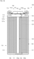
- FIGS. 1A , 1B , and 1C are a perspective view, a cross-sectional view, and an exploded perspective view illustrating a secondary battery 100 according to various embodiments of the present disclosure.
- the secondary battery 100 may include a cylindrical can 110, a cylindrical electrode assembly 120, and a cap assembly 140.
- the secondary battery 100 may further include a center pin 130 coupled to the electrode assembly 120.
- the cylindrical can 110 may include a circular bottom portion 111 and a cylindrical side portion 112 extending a predetermined length upward from the bottom portion 111. During the manufacturing process of the secondary battery, a top portion of the cylindrical can 110 is open. Therefore, during the assembling process of the secondary battery, the electrode assembly 120 may be inserted into the cylindrical can 110 together with an electrolyte.
- the cylindrical can 110 may include steel, a steel alloy, aluminum, an aluminum alloy, or an equivalent thereof.
- the cylindrical can 110 may include, with respect to the cap assembly 140, a beading part 113 that is recessed into the lower portion around the cap assembly 140 and a crimping part that is bent into the upper portion.
- the electrode assembly 120 may be accommodated inside the cylindrical can 110.
- the electrode assembly 120 may include a negative electrode plate 121 coated with a negative electrode active material (e.g., graphite, carbon, etc.) and a positive electrode plate coated with a positive electrode active material (e.g., transition metal oxide (LiCoO 2 , LiNiO 2 , LiMn 2 O 4 , etc.)) 122 and a separator 123 positioned between the negative electrode plate 121 and the positive electrode plate 122 to prevent a short circuit and to allow only the movement of lithium ions.
- the negative electrode plate 121, the positive electrode plate 122, and the separator 123 may be wound in a substantially cylindrical shape.
- the negative plate 121 may include a copper (Cu) or nickel (Ni) foil
- the positive plate 122 may include an aluminum (Al) foil
- the separator 123 may include polyethylene (PE) or polypropylene (PP), respectively.
- a negative electrode tab 124 protruding and extending downward by a certain length may be welded to the negative electrode plate 121
- a positive electrode tab 125 protruding upward by a certain length may be welded to the positive electrode plate 122, but the reverse is also possible.
- the negative electrode tab 124 may include a copper or nickel material
- the positive electrode tab 125 may include an aluminum material.
- the negative electrode tab 124 of the electrode assembly 120 may be welded to the bottom portion 111 of the cylindrical can 110. Therefore, the cylindrical can 110 may operate as a negative electrode.
- the positive electrode tab 125 may be welded to the bottom portion 111 of the cylindrical can 110, and in this case, the cylindrical can 110 may operate as a positive electrode.
- a first insulating plate 126 coupled to the cylindrical can 110 and having a first hole 126a in the center and a second hole 126b outside thereof, may be interposed between the electrode assembly 120 and the bottom portion 111.
- the first insulating plate 126 may prevent the electrode assembly 120 from electrically contacting the bottom portion 111 of the cylindrical can 110.
- the first insulating plate 126 may prevent the positive plate 122 of the electrode assembly 120 from electrically contacting the bottom portion 111.
- the first hole 126a may allow gas to quickly move upward through the center pin 130 when a large amount of gas is generated due to abnormality of the secondary battery, and the second hole 126b may allow the negative electrode tab 124 to pass therethrough and be welded to the bottom portion 111.
- a second insulating plate 127 coupled to the cylindrical can 110 and having a first hole 127a in the center and a plurality of second holes 127b outside thereof, may be interposed between the electrode assembly 120 and the cap assembly 140.
- the second insulating plate 127 may prevent the electrode assembly 120 from electrically contacting the cap assembly 140.
- the second insulating plate 127 may prevent the negative electrode plate 121 of the electrode assembly 120 from electrically contacting the cap assembly 140.
- the first hole 127a may allow gas to quickly move to the cap assembly 140 when a large amount of gas is generated due to abnormality of the secondary battery, and the second hole 127b may allow the positive electrode tab 125 to pass therethrough and be welded to the cap assembly 140.
- the remaining second holes 127b may allow the electrolyte to quickly flow into the electrode assembly 120 in an electrolyte injection process.
- the first holes 126a and 127a of the first and second insulating plates 126 and 127 are formed to smaller diameters of than the center pin 130, thereby preventing the center pin 130 from electrically contacting the bottom portion 111 of the cylindrical can 110 or the cap assembly 140 due to an external impact.
- the center pin 130 has a shape of a hollow circular pipe and may be coupled to approximately the center of the electrode assembly 120.
- the center pin 130 may include steel, a steel alloy, aluminum, an aluminum alloy, or polybutylene terephthalate.
- the center pin 130 serves to suppress deformation of the electrode assembly 120 during charging and discharging of the battery and serves as a passage for gas generated inside the secondary battery. In some cases, the center pin 130 may be omitted.
- the cap assembly 140 may include a cap-up portion 141 having a plurality of through holes 141a, a safety vent 142 located under the cap-up portion 141, a connection ring 143 located below the safety vent 142, and a cap-down portion 144 located below the safety vent 142 and the connection ring 143, having a plurality of through holes 144a, and electrically connected to the positive electrode tab 125.
- the cap assembly 140 may further include an insulating gasket 145 that insulates the cap-up portion 141, the safety vent 143, and the cap-down portion 144 from the side portion of the cylindrical can 110.
- the insulating gasket 145 may be compressed substantially between the beading part 113 and the crimping part 114 formed on the side portion 111 of the cylindrical can 110.
- the through hole 141a of the cap-up portion 141 and the through hole 144a of the cap-down portion 144 may discharge internal gas to the outside when abnormal pressure is generated inside the cylindrical can 110.
- the internal gas may invert the safety vent 143 upward through the through hole 144a of the cap-down portion 144, and thus, the safety vent 143 is electrically discharged from the cap-down portion 144. Then, while the safety vent 144 is torn (opened), the internal gas may be discharged to the outside through the through hole 141a of the cap-up portion 141.
- an electrolyte (not shown) may be injected into the cylindrical can 110, which enables movement of lithium ions generated by an electrochemical reaction in the negative electrode plate 121 and the positive electrode plate 122 inside the battery during charging and discharging.
- the electrolyte may include a non-aqueous organic electrolyte that is a mixture of a lithium salt and a high-purity organic solvent.
- the electrolyte may include a polymer using a polymer electrolyte or a solid electrolyte.
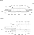
- FIG. 2 is a cross-sectional view showing an exemplary cap assembly 140 in an exemplary cylindrical secondary battery 100 according to the present disclosure.
- the cap assembly 140 may include a cap-up portion 141, a safety vent 142 disposed under the cap-up portion 141, a connection ring 143 disposed below the safety vent 142, and a cap-down portion 144 disposed below the connection ring 143.
- the cap-up portion 141 may include a cap-up contact part 141b that is in contact with the safety vent 142, a cap-up inclined part 141c that is inclined upward from the cap-up contact part 141b and has a plurality of through holes 141a, and a cap-up ceiling part 141d that extends in parallel from the cap-up inclined part 141c.
- an external device may be electrically connected to the cap-up ceiling part 141d.
- the safety vent 142 may include a vent contact part 142a that is in contact with the cap-up contact part 141b of the cap-up portion 141, a vent inclined part 142b that is inclined downward from the vent contact part 142a, a vent bottom part 142c that extends in parallel from the vent inclined part 142b, and a vent protruding part 142d that protrudes from the vent bottom part 142c and is in contact with (connected or linked to) the cap-down portion 144.
- the diameter (length or width) of the vent protruding part 142d may be approximately 60% to approximately 100% of the diameter (length or width) of the vent bottom part 142c.
- the vent protruding part 142d may be welded to the cap-down portion 144 by laser or ultrasonic waves, and thus, the vent protruding part 142d and the cap-down portion 144 may be in contact with (connected or linked to) each other.
- the vent contact part 142a may be bent multiple times to be in contact with the bottom, side, and top surfaces of the cap-up contact part 141b, respectively.
- the vent bottom part 142c may further include a substantially flat vent concave part 142e formed on an upper surface opposite to the vent protruding part 142d.
- the flat vent concave part 142e may be formed by being pressed by using a mold for forming the vent protruding part 142d on the vent bottom part 142c.
- the vent bottom part 142c of the safety vent 142 may further include a substantially linear vent concave part 142f formed on an upper surface opposite to the vent protruding part 142d.
- the vent concave part 142f in the form of a line is broken (opened) when the pressure inside the battery is higher than a preset pressure, and thus, the internal gas is discharged to the outside.
- the cap-down portion 144 may include a cap-down contact part 144b that is in contact with the connection ring 143, a cap-down inclined part 144c that is inclined downward from the cap-down contact part 144b, and a cap-down bottom part 144d that extends in parallel from the cap-down inclined part 144c.
- the connection ring 143 may be interposed between the vent contact part 142a and the cap-down contact part 144b.
- the cap-up portion 141, the safety vent 142, and the cap-down portion 144 include a metal material (e.g., aluminum, copper, or nickel), while the connection ring 143 includes an insulating material (e.g., polypropylene or polyethylene).
- the metal materials which form the safety vent 142 and the cap-down portion 144, and the elongation rates thereof will be described again below.
- the cap-down bottom part 144d may further include a through hole 144a that penetrates the cap-down bottom part 144d.
- a separation space S may be provided between the vent bottom part 142c and the cap-down bottom part 144d.
- a vertical separation distance between the vent bottom part 142c and the cap-down bottom part 144d may be about 0.20 mm to about 30 mm. As the separation distance increases, a wider elongation space of the cap-down portion 144 in the upward direction may be secured.
- the cap-down portion 144 may further include a flat cap-down concave part 144e formed on a lower surface.
- the negative electrode tab 125 (see FIG. 1B ) may be welded to the outer cap-down bottom part 144d of the flat cap-down concave part 144e.
- the elongation rate (%) of the cap-down portion 144 and the elongation rate (%) of the safety vent 142 may be different from each other.
- the elongation rate (%) of the cap-down portion 144 may be higher than the elongation rate (%) of the safety vent 142.
- the safety vent 142 and the cap-down portion 144 may include aluminum or an aluminum alloy, but the elongation rate (%) of the cap-down portion 144 may be greater than the elongation rate (%) of the safety vent 142.
- the cap-down portion 144 may include 1000-series aluminum, and the safety vent 142 may be an aluminum alloy of any one of 2000 series, 3000 series, 4000 series, 5000 series, 6000 series, and 7000 series.
- the cap-down portion 144 may include pure aluminum having a purity greater than 99%
- the safety vent 142 may include any one of an Al-Cu-based alloy, an Al-Mn-based alloy, an Al-Si-based alloy, an Al-Mg-based alloy, an Al-Mg-Si-based alloy, and an Al-Zn-(Mg, Cu)-based alloy.
- the cap-down portion 144 may include a 1050 series aluminum alloy
- the safety vent 142 may include a 3003 series or a 3005 series aluminum alloy.
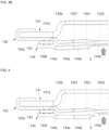
- FIGS. 3A and 3B are half cross-sectional views illustrating an operation of an exemplary cap assembly in an exemplary cylindrical secondary battery according to the present disclosure
- FIG. 4 is a half-sectional view illustrating an operation of a cap assembly in a cylindrical secondary battery according to a comparative example.
- FIG. 4 shows the operation of the safety vent 142 according to the increase in internal pressure, in a case where the materials of the safety vent 142 and the cap-down portion 144 are the same, for example, in a case where the materials of the safety vent 142 and the cap-down portion 144 are aluminum alloys, which are both 3000-series rigid materials.
- the safety vent 142 may be separated from the cap-down portion 144 after the cap-down portion 144 is elongated upward by a predetermined length as the internal pressure of the can 110 increases. Thereafter, when the internal pressure of the can 110 further increases, the safety vent 142 is eventually broken and opened, and thus, the gas inside the can 110 is discharged to the outside.
- the safety vent 142 may not immediately operate. However, as described above, the safety vent 142 may be separated from the cap-down portion 144 after the cap-down portion 144 is elongated upward, and the safety vent 142 may then be opened, thereby delaying the operation of the safety vent 142 when the secondary battery 100 is placed in a high-temperature environment.
- both the safety vent 142 and the cap-down portion 144 are made of aluminium alloys, which are rigid 3000-series materials, the safety vent 142 is immediately separated from the cap-down portion 144 without elongation of the cap-down portion 144, and the safety vent 142 is immediately opened, and thus, the safety vent 142 is opened too quickly.
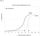
- FIG. 5 is a graph illustrating a relationship between internal pressure and displacement of an exemplary safety vent according to the present disclosure and a safety vent according to a comparative example.
- the X-axis indicates the internal pressure (kgf/cm 2 )
- the Y-axis indicates the displacement of safety vent.
- the safety vent is opened at an internal pressure of approximately 14
- the cap-down is made of a ductile material and the safety vent is made of a rigid material
- the safety vent was opened at an internal pressure of approximately 17. Accordingly, in a high-temperature environment, when the material of the cap-down is softer than the material of the safety vent, the opening time of the safety vent can be delayed, and thus the high-temperature characteristics of the secondary battery can be improved.
Landscapes
- Chemical & Material Sciences (AREA)
- Chemical Kinetics & Catalysis (AREA)
- Electrochemistry (AREA)
- General Chemical & Material Sciences (AREA)
- Inorganic Chemistry (AREA)
- Gas Exhaust Devices For Batteries (AREA)
- Sealing Battery Cases Or Jackets (AREA)
Applications Claiming Priority (2)
| Application Number | Priority Date | Filing Date | Title |
|---|---|---|---|
| KR1020200174409A KR20220084690A (ko) | 2020-12-14 | 2020-12-14 | 원통형 이차 전지 |
| PCT/KR2021/016461 WO2022131558A1 (fr) | 2020-12-14 | 2021-11-11 | Batterie secondaire cylindrique |
Publications (2)
| Publication Number | Publication Date |
|---|---|
| EP4262002A1 true EP4262002A1 (fr) | 2023-10-18 |
| EP4262002A4 EP4262002A4 (fr) | 2025-03-05 |
Family
ID=82059639
Family Applications (1)
| Application Number | Title | Priority Date | Filing Date |
|---|---|---|---|
| EP21906863.2A Pending EP4262002A4 (fr) | 2020-12-14 | 2021-11-11 | Batterie secondaire cylindrique |
Country Status (5)
| Country | Link |
|---|---|
| US (1) | US20230395932A1 (fr) |
| EP (1) | EP4262002A4 (fr) |
| KR (1) | KR20220084690A (fr) |
| CN (1) | CN116368667A (fr) |
| WO (1) | WO2022131558A1 (fr) |
Cited By (2)
| Publication number | Priority date | Publication date | Assignee | Title |
|---|---|---|---|---|
| EP4258458A4 (fr) * | 2021-10-22 | 2025-03-12 | LG Energy Solution, Ltd. | Ensemble capuchon et batterie secondaire le comprenant |
| EP4672452A1 (fr) * | 2024-06-24 | 2025-12-31 | Samsung Sdi Co., Ltd. | Ensemble capuchon, procédé de fabrication d'ensemble capuchon et batterie secondaire comprenant l'ensemble capuchon |
Families Citing this family (2)
| Publication number | Priority date | Publication date | Assignee | Title |
|---|---|---|---|---|
| KR20250139647A (ko) * | 2024-03-15 | 2025-09-23 | 삼성에스디아이 주식회사 | 이차 전지, 이차 전지 모듈 및 이차 전지 팩 |
| KR20250151028A (ko) * | 2024-04-12 | 2025-10-21 | 삼성에스디아이 주식회사 | 원통형 이차 전지 |
Family Cites Families (12)
| Publication number | Priority date | Publication date | Assignee | Title |
|---|---|---|---|---|
| KR100995764B1 (ko) * | 2006-12-04 | 2010-11-22 | 주식회사 엘지화학 | 용량이 증가된 원통형 전지 |
| KR100948001B1 (ko) * | 2006-12-11 | 2010-03-18 | 주식회사 엘지화학 | 안전성이 강화된 클림핑 형상의 리튬이온 이차전지 |
| KR101111073B1 (ko) * | 2007-09-12 | 2012-02-15 | 주식회사 엘지화학 | 이차전지용 캡 어셈블리 |
| KR100966549B1 (ko) * | 2008-10-14 | 2010-06-29 | 주식회사 엘지화학 | 안전성이 향상된 캡 어셈블리 및 이를 포함하고 있는 원통형 이차전지 |
| KR101093457B1 (ko) * | 2010-03-23 | 2011-12-13 | 주식회사 비츠로셀 | 리튬 전지 |
| JP5720956B2 (ja) * | 2012-05-18 | 2015-05-20 | トヨタ自動車株式会社 | 二次電池 |
| KR101772266B1 (ko) * | 2014-09-19 | 2017-08-30 | 신흥에스이씨주식회사 | 우수한 전기차단성을 구비한 이차전지용 캡조립체 및 그 이차전지 |
| KR102308423B1 (ko) * | 2017-04-24 | 2021-10-05 | 주식회사 엘지에너지솔루션 | 형상 기억 합금체가 형성되어 있는 탑 캡을 구비하는 전지셀 |
| KR102520538B1 (ko) * | 2017-12-05 | 2023-04-11 | 삼성에스디아이 주식회사 | 이차 전지 |
| US11664523B2 (en) * | 2017-12-13 | 2023-05-30 | Samsung Sdi Co., Ltd. | Secondary battery |
| KR102570969B1 (ko) * | 2018-02-01 | 2023-08-25 | 삼성에스디아이 주식회사 | 원통형 리튬 이온 이차 전지 |
| KR20230057686A (ko) * | 2021-10-22 | 2023-05-02 | 주식회사 엘지에너지솔루션 | 캡 어셈블리 및 이를 포함하는 이차 전지 |
-
2020
- 2020-12-14 KR KR1020200174409A patent/KR20220084690A/ko active Pending
-
2021
- 2021-11-11 CN CN202180072374.2A patent/CN116368667A/zh active Pending
- 2021-11-11 WO PCT/KR2021/016461 patent/WO2022131558A1/fr not_active Ceased
- 2021-11-11 EP EP21906863.2A patent/EP4262002A4/fr active Pending
- 2021-11-11 US US18/249,939 patent/US20230395932A1/en active Pending
Cited By (2)
| Publication number | Priority date | Publication date | Assignee | Title |
|---|---|---|---|---|
| EP4258458A4 (fr) * | 2021-10-22 | 2025-03-12 | LG Energy Solution, Ltd. | Ensemble capuchon et batterie secondaire le comprenant |
| EP4672452A1 (fr) * | 2024-06-24 | 2025-12-31 | Samsung Sdi Co., Ltd. | Ensemble capuchon, procédé de fabrication d'ensemble capuchon et batterie secondaire comprenant l'ensemble capuchon |
Also Published As
| Publication number | Publication date |
|---|---|
| KR20220084690A (ko) | 2022-06-21 |
| US20230395932A1 (en) | 2023-12-07 |
| EP4262002A4 (fr) | 2025-03-05 |
| CN116368667A (zh) | 2023-06-30 |
| WO2022131558A1 (fr) | 2022-06-23 |
Similar Documents
| Publication | Publication Date | Title |
|---|---|---|
| EP4262002A1 (fr) | Batterie secondaire cylindrique | |
| US12176568B2 (en) | Cylindrical lithium ion secondary battery | |
| US20240097291A1 (en) | Cylindrical lithium ion secondary battery | |
| EP3951915B1 (fr) | Batterie secondaire | |
| EP3726616A1 (fr) | Batterie secondaire cylindrique | |
| CN111566840B (zh) | 圆柱形锂离子二次电池 | |
| EP4258434A1 (fr) | Batterie secondaire cylindrique | |
| EP3726606A1 (fr) | Batterie secondaire | |
| EP4362177A2 (fr) | Batterie secondaire cylindrique | |
| EP4597656A1 (fr) | Batterie secondaire cylindrique | |
| EP4311005A1 (fr) | Batterie secondaire | |
| KR102794896B1 (ko) | 이차 전지 및 그 제조 방법 | |
| EP4220840A1 (fr) | Batterie secondaire cylindrique | |
| US20250087861A1 (en) | Secondary battery | |
| US20240234970A1 (en) | Cylindrical secondary battery | |
| EP4362178A1 (fr) | Batterie secondaire cylindrique | |
| KR20250151028A (ko) | 원통형 이차 전지 |
Legal Events
| Date | Code | Title | Description |
|---|---|---|---|
| STAA | Information on the status of an ep patent application or granted ep patent |
Free format text: STATUS: THE INTERNATIONAL PUBLICATION HAS BEEN MADE |
|
| PUAI | Public reference made under article 153(3) epc to a published international application that has entered the european phase |
Free format text: ORIGINAL CODE: 0009012 |
|
| STAA | Information on the status of an ep patent application or granted ep patent |
Free format text: STATUS: REQUEST FOR EXAMINATION WAS MADE |
|
| 17P | Request for examination filed |
Effective date: 20230323 |
|
| AK | Designated contracting states |
Kind code of ref document: A1 Designated state(s): AL AT BE BG CH CY CZ DE DK EE ES FI FR GB GR HR HU IE IS IT LI LT LU LV MC MK MT NL NO PL PT RO RS SE SI SK SM TR |
|
| DAV | Request for validation of the european patent (deleted) | ||
| DAX | Request for extension of the european patent (deleted) | ||
| A4 | Supplementary search report drawn up and despatched |
Effective date: 20250203 |
|
| RIC1 | Information provided on ipc code assigned before grant |
Ipc: H01M 50/171 20210101ALI20250128BHEP Ipc: H01M 50/169 20210101ALI20250128BHEP Ipc: H01M 50/107 20210101ALI20250128BHEP Ipc: H01M 50/159 20210101ALI20250128BHEP Ipc: H01M 50/152 20210101ALI20250128BHEP Ipc: H01M 50/342 20210101AFI20250128BHEP |