EP4261963A1 - Battery - Google Patents
Battery Download PDFInfo
- Publication number
- EP4261963A1 EP4261963A1 EP20965838.4A EP20965838A EP4261963A1 EP 4261963 A1 EP4261963 A1 EP 4261963A1 EP 20965838 A EP20965838 A EP 20965838A EP 4261963 A1 EP4261963 A1 EP 4261963A1
- Authority
- EP
- European Patent Office
- Prior art keywords
- electrode group
- electrode
- plate portion
- current collecting
- battery
- Prior art date
- Legal status (The legal status is an assumption and is not a legal conclusion. Google has not performed a legal analysis and makes no representation as to the accuracy of the status listed.)
- Withdrawn
Links
Images




Classifications
-
- H—ELECTRICITY
- H01—ELECTRIC ELEMENTS
- H01M—PROCESSES OR MEANS, e.g. BATTERIES, FOR THE DIRECT CONVERSION OF CHEMICAL ENERGY INTO ELECTRICAL ENERGY
- H01M50/00—Constructional details or processes of manufacture of the non-active parts of electrochemical cells other than fuel cells, e.g. hybrid cells
- H01M50/50—Current conducting connections for cells or batteries
- H01M50/528—Fixed electrical connections, i.e. not intended for disconnection
-
- H—ELECTRICITY
- H01—ELECTRIC ELEMENTS
- H01M—PROCESSES OR MEANS, e.g. BATTERIES, FOR THE DIRECT CONVERSION OF CHEMICAL ENERGY INTO ELECTRICAL ENERGY
- H01M50/00—Constructional details or processes of manufacture of the non-active parts of electrochemical cells other than fuel cells, e.g. hybrid cells
- H01M50/40—Separators; Membranes; Diaphragms; Spacing elements inside cells
- H01M50/471—Spacing elements inside cells other than separators, membranes or diaphragms; Manufacturing processes thereof
- H01M50/474—Spacing elements inside cells other than separators, membranes or diaphragms; Manufacturing processes thereof characterised by their position inside the cells
-
- H—ELECTRICITY
- H01—ELECTRIC ELEMENTS
- H01M—PROCESSES OR MEANS, e.g. BATTERIES, FOR THE DIRECT CONVERSION OF CHEMICAL ENERGY INTO ELECTRICAL ENERGY
- H01M10/00—Secondary cells; Manufacture thereof
- H01M10/05—Accumulators with non-aqueous electrolyte
- H01M10/058—Construction or manufacture
- H01M10/0587—Construction or manufacture of accumulators having only wound construction elements, i.e. wound positive electrodes, wound negative electrodes and wound separators
-
- H—ELECTRICITY
- H01—ELECTRIC ELEMENTS
- H01M—PROCESSES OR MEANS, e.g. BATTERIES, FOR THE DIRECT CONVERSION OF CHEMICAL ENERGY INTO ELECTRICAL ENERGY
- H01M50/00—Constructional details or processes of manufacture of the non-active parts of electrochemical cells other than fuel cells, e.g. hybrid cells
- H01M50/10—Primary casings; Jackets or wrappings
- H01M50/102—Primary casings; Jackets or wrappings characterised by their shape or physical structure
- H01M50/103—Primary casings; Jackets or wrappings characterised by their shape or physical structure prismatic or rectangular
-
- H—ELECTRICITY
- H01—ELECTRIC ELEMENTS
- H01M—PROCESSES OR MEANS, e.g. BATTERIES, FOR THE DIRECT CONVERSION OF CHEMICAL ENERGY INTO ELECTRICAL ENERGY
- H01M50/00—Constructional details or processes of manufacture of the non-active parts of electrochemical cells other than fuel cells, e.g. hybrid cells
- H01M50/10—Primary casings; Jackets or wrappings
- H01M50/147—Lids or covers
-
- H—ELECTRICITY
- H01—ELECTRIC ELEMENTS
- H01M—PROCESSES OR MEANS, e.g. BATTERIES, FOR THE DIRECT CONVERSION OF CHEMICAL ENERGY INTO ELECTRICAL ENERGY
- H01M50/00—Constructional details or processes of manufacture of the non-active parts of electrochemical cells other than fuel cells, e.g. hybrid cells
- H01M50/10—Primary casings; Jackets or wrappings
- H01M50/147—Lids or covers
- H01M50/148—Lids or covers characterised by their shape
- H01M50/15—Lids or covers characterised by their shape for prismatic or rectangular cells
-
- H—ELECTRICITY
- H01—ELECTRIC ELEMENTS
- H01M—PROCESSES OR MEANS, e.g. BATTERIES, FOR THE DIRECT CONVERSION OF CHEMICAL ENERGY INTO ELECTRICAL ENERGY
- H01M50/00—Constructional details or processes of manufacture of the non-active parts of electrochemical cells other than fuel cells, e.g. hybrid cells
- H01M50/10—Primary casings; Jackets or wrappings
- H01M50/147—Lids or covers
- H01M50/166—Lids or covers characterised by the methods of assembling casings with lids
- H01M50/169—Lids or covers characterised by the methods of assembling casings with lids by welding, brazing or soldering
-
- H—ELECTRICITY
- H01—ELECTRIC ELEMENTS
- H01M—PROCESSES OR MEANS, e.g. BATTERIES, FOR THE DIRECT CONVERSION OF CHEMICAL ENERGY INTO ELECTRICAL ENERGY
- H01M50/00—Constructional details or processes of manufacture of the non-active parts of electrochemical cells other than fuel cells, e.g. hybrid cells
- H01M50/10—Primary casings; Jackets or wrappings
- H01M50/172—Arrangements of electric connectors penetrating the casing
- H01M50/174—Arrangements of electric connectors penetrating the casing adapted for the shape of the cells
- H01M50/176—Arrangements of electric connectors penetrating the casing adapted for the shape of the cells for prismatic or rectangular cells
-
- H—ELECTRICITY
- H01—ELECTRIC ELEMENTS
- H01M—PROCESSES OR MEANS, e.g. BATTERIES, FOR THE DIRECT CONVERSION OF CHEMICAL ENERGY INTO ELECTRICAL ENERGY
- H01M50/00—Constructional details or processes of manufacture of the non-active parts of electrochemical cells other than fuel cells, e.g. hybrid cells
- H01M50/40—Separators; Membranes; Diaphragms; Spacing elements inside cells
- H01M50/471—Spacing elements inside cells other than separators, membranes or diaphragms; Manufacturing processes thereof
- H01M50/477—Spacing elements inside cells other than separators, membranes or diaphragms; Manufacturing processes thereof characterised by their shape
-
- H—ELECTRICITY
- H01—ELECTRIC ELEMENTS
- H01M—PROCESSES OR MEANS, e.g. BATTERIES, FOR THE DIRECT CONVERSION OF CHEMICAL ENERGY INTO ELECTRICAL ENERGY
- H01M50/00—Constructional details or processes of manufacture of the non-active parts of electrochemical cells other than fuel cells, e.g. hybrid cells
- H01M50/50—Current conducting connections for cells or batteries
- H01M50/531—Electrode connections inside a battery casing
-
- H—ELECTRICITY
- H01—ELECTRIC ELEMENTS
- H01M—PROCESSES OR MEANS, e.g. BATTERIES, FOR THE DIRECT CONVERSION OF CHEMICAL ENERGY INTO ELECTRICAL ENERGY
- H01M50/00—Constructional details or processes of manufacture of the non-active parts of electrochemical cells other than fuel cells, e.g. hybrid cells
- H01M50/50—Current conducting connections for cells or batteries
- H01M50/531—Electrode connections inside a battery casing
- H01M50/533—Electrode connections inside a battery casing characterised by the shape of the leads or tabs
-
- H—ELECTRICITY
- H01—ELECTRIC ELEMENTS
- H01M—PROCESSES OR MEANS, e.g. BATTERIES, FOR THE DIRECT CONVERSION OF CHEMICAL ENERGY INTO ELECTRICAL ENERGY
- H01M50/00—Constructional details or processes of manufacture of the non-active parts of electrochemical cells other than fuel cells, e.g. hybrid cells
- H01M50/50—Current conducting connections for cells or batteries
- H01M50/531—Electrode connections inside a battery casing
- H01M50/536—Electrode connections inside a battery casing characterised by the method of fixing the leads to the electrodes, e.g. by welding
-
- H—ELECTRICITY
- H01—ELECTRIC ELEMENTS
- H01M—PROCESSES OR MEANS, e.g. BATTERIES, FOR THE DIRECT CONVERSION OF CHEMICAL ENERGY INTO ELECTRICAL ENERGY
- H01M50/00—Constructional details or processes of manufacture of the non-active parts of electrochemical cells other than fuel cells, e.g. hybrid cells
- H01M50/50—Current conducting connections for cells or batteries
- H01M50/531—Electrode connections inside a battery casing
- H01M50/538—Connection of several leads or tabs of wound or folded electrode stacks
-
- H—ELECTRICITY
- H01—ELECTRIC ELEMENTS
- H01M—PROCESSES OR MEANS, e.g. BATTERIES, FOR THE DIRECT CONVERSION OF CHEMICAL ENERGY INTO ELECTRICAL ENERGY
- H01M50/00—Constructional details or processes of manufacture of the non-active parts of electrochemical cells other than fuel cells, e.g. hybrid cells
- H01M50/50—Current conducting connections for cells or batteries
- H01M50/543—Terminals
- H01M50/547—Terminals characterised by the disposition of the terminals on the cells
- H01M50/55—Terminals characterised by the disposition of the terminals on the cells on the same side of the cell
-
- H—ELECTRICITY
- H01—ELECTRIC ELEMENTS
- H01M—PROCESSES OR MEANS, e.g. BATTERIES, FOR THE DIRECT CONVERSION OF CHEMICAL ENERGY INTO ELECTRICAL ENERGY
- H01M50/00—Constructional details or processes of manufacture of the non-active parts of electrochemical cells other than fuel cells, e.g. hybrid cells
- H01M50/50—Current conducting connections for cells or batteries
- H01M50/543—Terminals
- H01M50/552—Terminals characterised by their shape
- H01M50/553—Terminals adapted for prismatic, pouch or rectangular cells
-
- H—ELECTRICITY
- H01—ELECTRIC ELEMENTS
- H01M—PROCESSES OR MEANS, e.g. BATTERIES, FOR THE DIRECT CONVERSION OF CHEMICAL ENERGY INTO ELECTRICAL ENERGY
- H01M50/00—Constructional details or processes of manufacture of the non-active parts of electrochemical cells other than fuel cells, e.g. hybrid cells
- H01M50/50—Current conducting connections for cells or batteries
- H01M50/572—Means for preventing undesired use or discharge
- H01M50/584—Means for preventing undesired use or discharge for preventing incorrect connections inside or outside the batteries
- H01M50/59—Means for preventing undesired use or discharge for preventing incorrect connections inside or outside the batteries characterised by the protection means
- H01M50/593—Spacers; Insulating plates
-
- Y—GENERAL TAGGING OF NEW TECHNOLOGICAL DEVELOPMENTS; GENERAL TAGGING OF CROSS-SECTIONAL TECHNOLOGIES SPANNING OVER SEVERAL SECTIONS OF THE IPC; TECHNICAL SUBJECTS COVERED BY FORMER USPC CROSS-REFERENCE ART COLLECTIONS [XRACs] AND DIGESTS
- Y02—TECHNOLOGIES OR APPLICATIONS FOR MITIGATION OR ADAPTATION AGAINST CLIMATE CHANGE
- Y02E—REDUCTION OF GREENHOUSE GAS [GHG] EMISSIONS, RELATED TO ENERGY GENERATION, TRANSMISSION OR DISTRIBUTION
- Y02E60/00—Enabling technologies; Technologies with a potential or indirect contribution to GHG emissions mitigation
- Y02E60/10—Energy storage using batteries
-
- Y—GENERAL TAGGING OF NEW TECHNOLOGICAL DEVELOPMENTS; GENERAL TAGGING OF CROSS-SECTIONAL TECHNOLOGIES SPANNING OVER SEVERAL SECTIONS OF THE IPC; TECHNICAL SUBJECTS COVERED BY FORMER USPC CROSS-REFERENCE ART COLLECTIONS [XRACs] AND DIGESTS
- Y02—TECHNOLOGIES OR APPLICATIONS FOR MITIGATION OR ADAPTATION AGAINST CLIMATE CHANGE
- Y02P—CLIMATE CHANGE MITIGATION TECHNOLOGIES IN THE PRODUCTION OR PROCESSING OF GOODS
- Y02P70/00—Climate change mitigation technologies in the production process for final industrial or consumer products
- Y02P70/50—Manufacturing or production processes characterised by the final manufactured product
Definitions
- Embodiments described herein of this invention relate generally to batteries.
- a lithium ion secondary battery is an example of a secondary battery that is reduced in size and weight and that has a high energy density.
- secondary batteries such as lead-acid storage batteries and nickel-metal hydride batteries are used as large-sized, high-capacity power sources mounted on vehicles such as electric automobiles, hybrid automobiles, electric motorcycles or forklifts.
- lithium-ion secondary batteries with a high energy density have been developed for use as large-sized, high-capacity power sources to be mounted on vehicles. In the development of lithium-ion secondary batteries to be mounted on vehicles, it is required to realize longer battery life and improved safety, as well as to increase the size and capacity of the batteries.
- a battery such as a lithium ion secondary battery
- an electrode group including a positive electrode and a negative electrode is housed in the inner cavity of a container.
- the container has a bottom wall and a peripheral wall, and the inner cavity of the container is open in the height direction such that the opening is opposite to the bottom wall.
- a lid member is attached to the peripheral wall of the container, and the opening of the inner cavity is closed by the lid member.
- electrode terminal is arranged on the outer surface of the lid member in the state where they are exposed to the outside.
- the battery in which an electrode group is arranged inside the inner cavity of the container includes a battery in which current collecting tab protrudes toward the side where the lid member is located in the electrode group.
- a lead is arranged between the electrode group and the lid member in the height direction of the battery, and the electrode terminal is electrically connected to the current collecting tab by means of the lead or the like.
- an electrically insulating spacer covers the lead and current collecting tab from the outer peripheral side.
- the spacer prevents the lead and current collecting tab from coming into contact with the container and electrically isolates the lead and current collecting tab from the container. Further, in the battery, the spacer comes into contact with the electrode group from the side where the lid member is located in the height direction, and restricts the movement of the electrode group along the height direction.
- the problem to be solved by the present invention is to provide a battery in which the current collecting tab protrudes toward the side where the lid member is located in the electrode group, and the components arranged in the inner cavity of the container and the lid member can be easily assembled with each other.
- a battery includes a container, a lid member, an electrode group, a current collecting tab, an electrode terminal, a lead and a spacer.
- the container includes a bottom wall and a peripheral wall and defines an inner cavity that is open in a height direction toward a side opposite to a side where the bottom wall is located.
- the lid member is attached to the peripheral wall of the container in a state in which an opening of the inner cavity is closed.
- the electrode group includes a positive electrode and a negative electrode and is arranged in the inner cavity of the container.
- the current collecting tab protrudes in the electrode group toward a side where the lid member is located.
- the electrode terminal is exposed in an outer surface of the lid member.
- the lead is arranged between the electrode group and the lid member in the inner cavity and electrically connects the current collecting tab and the electrode terminal to each other.
- the spacer is integrally formed of an electrically insulating material.
- the spacer includes a top plate portion sandwiched between the lead and the lid member, and a peripheral plate portion extending from the top plate portion toward a side where the electrode group is located and covering the lead and the current collecting tab in the inner cavity from an outer peripheral side.
- the peripheral plate portion of the spacer comes into contact with the electrode group from a side where the lid member is located.
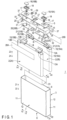
- FIGS. 1 and 2 show a battery 1 according to the first embodiment.
- the battery 1 includes an electrode group 2, a container 3 and a lid member 5.
- Each of the container 3 and the lid member 5 is made of metal, such as aluminum, aluminum alloy, iron, copper or stainless steel.
- the battery 1 (the container 3) is defined in terms of a depth direction (the direction indicated by arrows X1 and X2), a lateral direction (the direction indicated by arrows Y1 and Y2) intersecting the depth direction (perpendicular or substantially perpendicular thereto), and a height direction (the direction indicated by arrows Z1 and Z2) intersecting both the depth direction and the lateral direction (perpendicular or substantially perpendicular thereto).
- FIG. 1 is a perspective view showing each member of the battery 1 in an exploded manner
- FIG. 2 is a perspective view.
- the container 3 includes a bottom wall 6 and peripheral wall 7. Inside the container 3, an inner cavity 8 in which the electrode group 2 is housed is defined by the bottom wall 6 and the peripheral wall 7. In the height direction, the inner cavity 8 of the container 3 is open toward the side opposite to the side where the bottom wall 6 is located.
- the peripheral wall 7 include two pairs of side walls 11 and 12. The pair of side walls 11 are opposed to each other such that the inner cavity 8 is sandwiched in the lateral direction. The pair of side walls 12 are opposed to each other such that the inner cavity 8 is sandwiched in the depth direction. Each of the side walls 11 continuously extends along the depth direction between the side walls 12. Each of the side walls 12 continuously extends along the lateral direction between the side walls 11.
- the lid member 5 is attached to the peripheral wall 7 in an end portion opposite to the bottom wall 6. Therefore, the lid member 5 closes the opening of the inner cavity 8 of the container 3.
- the lid member 5 and the bottom wall 6 face each other, with the inner cavity 8 located therebetween in the height direction.
- two electrode groups 2 are arranged in the inner cavity 8.
- a plurality of electrode groups 2 (two electrode groups 2) are arranged side by side in the depth direction.
- One of the two electrode groups 2 will be referred to as an electrode group 2A (first electrode group), and the other one different from the electrode group 2A will be referred to as an electrode group 2B (second electrode group).
- the electrode group 2B is arranged adjacent to the electrode group 2A in the depth direction.
- Each of the electrode groups 2 includes a positive electrode 13A and a negative electrode 13B.
- a separator (not shown) is interposed between the positive electrode 13A and the negative electrode 13B.
- the separator is formed of an electrically insulating material, and electrically insulates the positive electrode 13A from the negative electrode 13B.
- the positive electrode 13A includes a positive electrode current collector, such as a positive electrode current collector foil, and a positive electrode active material-containing layer (not shown) supported on the surface of the positive electrode current collector.
- the positive electrode current collector is, for example, an aluminum foil, an aluminum alloy foil or the like and has a thickness of about 10 ⁇ m to 20 um, but the positive electrode current collector is not limited to this.
- the positive electrode active material-containing layer includes a positive electrode active material and may optionally include a binder and a conductive agent. Examples of the positive electrode active material are an oxide, a sulfide and a polymer that can occlude and release lithium ions, but the positive electrode active material is not limited to these examples.
- the positive electrode current collector includes a positive electrode current collecting tab 15A as a portion on which the positive electrode active material-containing layer is not supported.
- the negative electrode 13B includes a negative electrode current collector, such as a negative electrode current collector foil, and a negative electrode active material-containing layer (not shown) supported on the surface of the negative electrode current collector.
- the negative electrode current collector is, for example, an aluminum foil, an aluminum alloy foil, a copper foil or the like and has a thickness of about 10 ⁇ m to 20 ⁇ m, but is not limited to this example.
- the negative electrode active material-containing layer contains a negative electrode active material and may optionally contain a binder and a conductive agent. Examples of the negative electrode active material include a metal oxide, a metal sulfide, a metal nitride and a carbon material that can occlude and release lithium ions, but the negative electrode active material is not limited to these examples.
- the negative electrode current collector includes a negative electrode current collecting tab 15B as a portion where the negative electrode active material-containing layer is not supported.
- the positive electrode 13A, the negative electrode 13B and the separator are wound, with the winding axis B as a center, in the state where the separator is sandwiched between the positive electrode active material-containing layer and the negative electrode active material-containing layer.
- the outermost portion of the wound structure is made of an electrically insulating material.
- the outermost portion of the wound structure is made of a separator.
- the positive electrode current collecting tab 15A protrudes from the positive electrode active material-containing layer, the negative electrode active material-containing layer and the separator toward one side in the axial direction (the direction indicated by arrows Z3 and Z4) along the winding axis B.
- the negative electrode current collecting tab 15B protrudes from the positive electrode active material-containing layer, the negative electrode active material-containing layer and the separator toward the side where the positive electrode current collecting tab 15A protrudes, in the axial direction along the winding axis B. Therefore, in each of the electrode groups 2, the pair of current collecting tabs 15 (namely, the positive electrode current collecting tab 15A and the negative electrode current collecting tab 15B) protrude toward the same side in the axial direction along the winding axis B.
- Each of the electrode groups 2 is defined in terms of a width direction (the direction indicated by arrows Y3 and Y4) intersecting (perpendicular or substantially perpendicular to) the axial direction of the winding axis B (the protruding direction of the current collecting tabs 15), and a thickness direction (the direction indicated by arrows X3 and X4) intersecting both the axial direction of the winding axis B and the width direction.
- the dimension in the thickness direction is smaller than the dimension in the axial direction and the dimension in the width direction.
- each of the electrode groups 2 is formed having a flat shape. Further, in each of the pair of current collecting tabs 15 of each electrode group 2, a plurality of belt-like portions are bound.
- each of the electrode groups 2 is arranged in the inner cavity 8 in the state where the winding axis B is along the height direction of the battery 1, that is, in the state where the axial direction corresponds or substantially corresponds to the height direction of the battery 1.
- the width direction corresponds or substantially corresponds to the lateral direction of the battery 1
- the thickness direction corresponds or substantially corresponds to the depth direction of the battery 1.
- Each of the electrode groups 2 is arranged in the inner cavity 8 in a state where a pair of current collecting tabs 15 protrude toward the side where the lid member 5 is located in the height direction of the battery 1.
- the pair of current collecting tabs 15 are arranged apart from each other in the lateral direction of the battery 1. Therefore, in each of the electrode groups 2, the positive electrode current collecting tab 15A does not come into contact with the negative electrode current collecting tab 15B.
- each of the electrode groups 2 holds (is impregnated with) an electrolytic solution (not shown).
- the electrolytic solution may be a non-aqueous electrolytic solution in which an electrolyte is dissolved in an organic solvent, or an aqueous electrolytic solution such as an aqueous solution.
- a gel electrolyte may be used instead of the electrolytic solution, or a solid electrolyte may be used.
- the solid electrolyte in each of the electrode groups 2 is interposed between the positive electrode 13A and the negative electrode 13B, in place of the separator. In this case, in each of the electrode groups 2, the solid electrolyte electrically insulates the positive electrode 13A from the negative electrode 13B.
- a pair of electrode terminals 16 are attached to the lid member 5.
- the electrode terminals 16 are made of a conductive material such as metal.
- One of the pair of electrode terminals 16 is a positive terminal (16A) of the battery 1, and the other one of the pair of electrode terminals 16, which is different from the positive terminal (16A), is a negative terminal (16B) of the battery 1.
- Each of the electrode terminals 16 is arranged on the outer surface of the lid member 5 in a state where they are exposed to the outside of the battery 1.
- the pair of electrode terminals 16 are arranged apart from each other in the lateral direction of the battery 1.
- a pair of through-holes 17 are formed in the lid member 5, and each of the through-holes 17 penetrates the lid member 5 in the height direction of the battery 1.
- an insulating member 18 is provided between each of the electrode terminals 16 and the lid member 5.
- An insulating gasket 19 is arranged in each of the through-holes 17.
- Each of the electrode terminals 16 is electrically insulated from the lid member 5 and the container 3 by the insulating member 18 and the insulating gasket 19.
- a pair of leads 20 and a pair of backup leads 21 are arranged in the inner cavity 8 of the container 3.
- Each of the leads 20 and the backup leads 21 is made of a conductive material such as metal, and examples of materials forming the leads 20 and the backup leads 21 include aluminum, stainless steel, copper and iron.
- the leads 20 are arranged between the electrode groups 2 and the lid member 5 in the height direction of the battery 1.
- One of the pair of leads 20 is a positive electrode side lead (20A), and the other one of the pair of leads 20, which is different from the positive electrode side lead, is a negative electrode side lead (20B).
- One of the pair of backup leads 21 is a positive electrode side backup lead (21A), and the other one of the pair of backup leads 21, which is different from the positive electrode side backup lead (21A), is a negative electrode side backup lead (21B).
- the positive electrode side lead 20A and the positive electrode side backup lead 21A are arranged apart from the negative electrode side lead 20B and the negative electrode side backup lead 21B in the lateral direction of the battery 1. Therefore, the positive electrode side lead 20A and the positive electrode side backup lead 21A do not come into contact with the negative electrode side lead 20B and the negative electrode side backup lead 21B, respectively.
- the positive electrode current collecting tab 15A of each of the electrode groups 2 is electrically connected to the positive terminal 16A, via the backup lead 21A and the lead 20A in this order. Therefore, the lead 20A forms at least part of an electrical path between the positive electrode current collecting tab 15A and the positive terminal 16A.
- the negative electrode current collecting tab 15B of each of the electrode groups 2 is electrically connected to the negative terminal 16B, via the backup lead 21B and the lead 20B in this order. Therefore, the lead 20B forms at least part of an electrical path between the negative electrode current collecting tab 15B and the negative terminal 16B.
- An insulating tape 23 is attached to each of the electrode groups 2 from the side where the bottom wall 6 is located in the height direction.
- the insulating tape 23 is made of an electrically insulating material.
- the insulating tape 23 is closely attached and adhered to each of the electrode groups 2 in the inner cavity 8 and is sandwiched between each of the electrode groups 2 and the bottom wall 6 in the height direction of the battery 1.
- the two (plurality of) electrode groups 2 are bundled into one by the insulating tape 23.
- a spacer 25 is incorporated in the inner cavity 8 of the container 3.
- the spacer 25 is integrally formed of an electrically insulating material.
- the spacer 25 is arranged between the electrode groups 2 and the lid member 5 in the height direction of the battery 1.
- an insulating tape 26A is attached to the electrode group 2A and the spacer 25, and an insulating tape 26B is attached to the electrode group 2B and the spacer 25.
- Each of the insulating tapes 26A and 26B is made of an electrically insulating material.
- the insulating tape 26A is closely attached and adhered to the electrode group 2A and the spacer 25 and secures the electrode group 2A to the spacer 25.
- the insulating tape 26B is closely attached and adhered to the electrode group 2B and the spacer 25 and secures the electrode group 2B to the spacer 25.
- the spacer 25 and the insulating tapes 26A and 26B prevent the pair of current collecting tabs 15 of each of the electrode groups 2, the pair of leads 20 and the pair of backup leads 21 from coming into contact with the container 3 and the lid member 5. Therefore, the spacer 25 and the insulating tapes 26A and 26B electrically insulate the current collecting tabs 15, the leads 20 and the backup leads 21 from the container 3 and the lid member 5.
- the lid member 5 has a gas release valve 27 and a liquid injection port 28.
- a sealing plate 29 that closes the liquid injection port 28 is welded to the outer surface of the lid member 5.
- the gas release valve 27 and the liquid injection port 28 are arranged between the electrode terminals 16 in the lateral direction of the battery 1. It should be noted that in one example, the gas release valve 27 and the liquid injection port 28 need not be provided for the battery 1.
- FIG. 3 shows an assembled body into which the internal components in the inner cavity 8, the lid member 5 etc. are assembled.
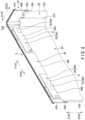
- FIGS. 4 and 5 show the lid member 5 and its neighboring structure in the assembled body shown in FIG. 3 .
- FIGS. 4 and 5 are views of different viewing directions, and illustration of the insulating tapes 26A and 26B described above is omitted.
- each of the pair of leads 20 includes a lead top plate portion 31 and a lead side plate portion 32.
- Each of the leads 20 is arranged in the inner cavity 8 in a state where the thickness direction of the lead top plate portion 31 corresponds or substantially corresponds to the height direction of the battery 1 and where the thickness direction of the lead side plate portion 32 corresponds or substantially corresponds to the depth direction of the battery 1.
- the lead side plate portion 32 is bent with respect to the lead top plate portion 31 toward the side where the electrode groups 2 (bottom wall 6) are located in the height direction of the battery 1.
- the lead side plate portion 32 is connected to one side edge of the lead top plate portion 31 in the depth direction of the battery 1.
- an "L" shape or a substantial "L” shape is formed by the lead top plate portion 31 and the lead side plate portion 32 in a cross section perpendicular or substantially perpendicular to the lateral direction of the battery 1.
- Each of the leads 20 has a through-hole 33 that penetrates the lead top plate portion 31 in the height direction of the battery 1 (in the thickness direction of the lead top plate portion 31).
- a corresponding one of the electrode terminals 16 is connected to each of the leads 20 at the through-hole 33. Therefore, in each of the leads 20, the through-hole 33 of the lead top plate portion 31 serves as a connection position of the corresponding one of the electrode terminals 16.
- the corresponding one of the electrode terminals 16 is connected to each of the leads 20 by caulking or the like.
- the backup leads 21A sandwich the binding portion of the positive electrode current collecting tab 15A of the electrode group 2A and the binding portion of the positive electrode current collecting tab 15A of the electrode group 2B.
- the binding portions of the positive electrode current collecting tabs 15A of the two electrode groups 2 are joined to the lead 20A, with the backup lead 21A interposed therebetween.
- the positive electrode current collecting tabs 15A are joined to the lead side plate portion 32, and the positive electrode current collecting tabs 15A are joined, for example, by ultrasonic welding.
- the backup leads 21B sandwich the binding portion of the negative electrode current collecting tab 15B of the electrode group 2A and the binding portion of the negative electrode current collecting tab 15B of the electrode group 2B.
- the binding portions of the negative electrode current collecting tabs 15B of the two electrode groups 2 are joined to the lead 20B, with the backup lead 21B interposed therebetween.
- the negative electrode current collecting tabs 15B are joined to the lead side plate portion 32, and the negative electrode current collecting tabs 15B are joined, for example, by ultrasonic welding.
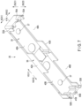
- FIGS. 6 and 7 show the spacer 25.
- FIGS. 6 and 7 differ from each other in viewing direction.
- the spacer 25 is defined in terms of a length direction (the direction indicated by arrows Y5 and Y6), a width direction (the direction indicated by arrows X5 and X6) intersecting the length direction (perpendicular or substantially perpendicular thereto), and a height direction (the direction indicated by arrows Z5 and Z6) intersecting both the length direction and the width direction (perpendicular or nearly perpendicular thereto).
- the dimension in the length direction is larger than the dimension in the width direction and the dimension in the height direction.
- the spacer 25 is arranged in the inner cavity 8 in the state where the height direction thereof corresponds or substantially corresponds to the height direction of the battery 1 and the width direction thereof corresponds or substantially corresponds to the depth direction of the battery 1. Therefore, in the spacer 25 arranged in the inner cavity 8, the length direction corresponds or substantially corresponds to the lateral direction of the battery 1.
- the spacer 25 includes a top plate portion 35 and a peripheral plate portion 36.
- the top plate portion 35 is sandwiched between the lead top plate portion 31 of each of the leads 20 and the lid member 5 in the height direction of the battery 1.
- the top plate portion 35 prevents the leads 20 and current collecting tabs 15 from coming into contact with the lid member 5.
- the top plate portion 35 is arranged in the inner cavity 8 in the state where the thickness direction thereof corresponds or substantially corresponds to the height direction of the spacer 25, that is, in the state where the thickness direction thereof corresponds or substantially corresponds to the height direction of the battery 1.
- a pair of through-holes 37 are formed in the top plate portion 35 along the height direction of the spacer 25 (the thickness direction of the top plate portion 35). Each of the through-holes 37 penetrates the top plate portion 35 along the height direction of the battery 1. The pair of through-holes 37 are arranged apart from each other in the lateral direction of the battery 1 (in the length direction of the spacer 25). Each of the electrode terminals 16 is inserted through the corresponding one of the through-holes 17 of the lid member 5, the corresponding one of the through-holes 37 of the spacer 25, and the through-hole 33 of the corresponding one of the leads 20, in the order mentioned. Each of the electrode terminals 16 is connected to the corresponding one of the leads 20 at the through-hole 33, as described above.
- the peripheral plate portion 36 extends from the outer edge of the top plate portion 35 toward the side where the electrode groups 2 (bottom wall 6) are located in the height direction of the battery 1. Therefore, the peripheral plate portion 36 protrudes from the top plate portion 35 toward the side where the electrode groups 2 are located.
- the peripheral plate portion 36 extends along the outer edge of the top plate portion 35 and is formed over the entire circumference of an outer periphery of the top plate portion 35.
- the two pairs of current collecting tabs 15 and the one pair of leads 20 are covered from the outer peripheral side of the inner cavity 8 by the peripheral plate portion 36 of the spacer 25.
- the peripheral plate portion 36 covers the current collecting tabs 15 and the leads 20 over the entire circumference of the inner cavity 8 in the circumferential direction.
- the peripheral plate portion 36 includes a pair of side plate portions 41A and 41B and a pair of side plate portions 42A and 42B.
- the side plate portions 41A and 41B face each other, with the current collecting tabs 15 and the leads 20 being interposed therebetween in the lateral direction of the battery 1 (the length direction of the spacer 25). Therefore, the side plate portion 41A covers the current collecting tabs 15 and the leads 20 from one side in the lateral direction of the battery 1, and the side plate portion 41B covers the current collecting tabs 15 and the leads 20 from the side opposite to the side plate portion 41A in the lateral direction of the battery 1.
- the side plate portions 42A and 42B face each other, with the current collecting tabs 15 and the leads 20 interposed therebetween in the depth direction of the battery 1 (the width direction of the spacer 25). Therefore, the side plate portion 42A covers the current collecting tabs 15 and the leads 20 from one side in the depth direction of the battery 1, and the side plate portion 42B covers the current collecting tabs 15 and the leads 20 from the side opposite to the side plate portion 42A in the depth direction of the battery 1.
- Each of the side plate portions 41A and 41B extends continuously along the depth direction of the battery 1 between the side plate portions 42A and 42B.
- the thickness direction of each of the side plate portions 41A and 41B corresponds or substantially corresponds to the lateral direction of the battery 1 and corresponds or substantially corresponds to the length direction of the spacer 25.
- each of the side plate portions 42A and 42B extends continuously along the lateral direction of the battery 1 between the side plate portions 41A and 41B.
- the thickness direction of each of the side plate portions 42A and 42B corresponds or substantially corresponds to the depth direction of the battery 1 and corresponds or substantially corresponds to the width direction of the spacer 25.
- the peripheral plate portion 36 is located between the top plate portion 35 of the spacer 25 and the electrode groups 2, in the height direction of the battery 1.
- the peripheral plate portion 36 of the spacer 25 comes into contact with each of the electrode groups 2 from the side where the lid member 5 is located in the height direction of the battery 1. Therefore, each of the electrode groups 2 is pressed by the peripheral plate portion 36 of the spacer 25 toward the side where the bottom wall 6 is located in the height direction of the battery 1. Pressed by the peripheral plate portion 36, movement of the electrode groups 2 along the height direction of the battery 1 is restricted in the inner cavity 8.
- the peripheral plate portion 36 comes into contact with each of the electrode groups 2 at the protruding end of the protruding portion from the top plate portion 35 toward the side where the electrode groups 2 are located.
- Through-holes 45A, 45B, 46A and 46B penetrating the peripheral plate portion 36 are formed in the peripheral plate portion 36.
- Each of the through-holes 45A and 45B is formed in the side plate portion 42A and penetrates the side plate portion 42A along the depth direction of the battery 1.
- Each of the through-holes 46A and 46B is formed in the side plate portion 42B and penetrates the side plate portion 42B along the depth direction of the battery 1.
- the through-holes 45A and 46A are formed apart from the through-holes 45B and 46B in the lateral direction of the battery 1 (the length direction of the spacer 25).
- the central position of the spacer 25 in the lateral direction of the battery 1 is located between the through-holes 45A and 45B and between the through-holes 46A and 46B.
- the through-hole 45A is not shifted or is hardly shifted from the through-hole 46A in the lateral direction and the height direction of the battery 1. Therefore, the through-hole 45A (first through-hole) overlaps the through-hole 46A (second through-hole) when they are projected from the depth direction of the battery 1.
- the through-holes 45A and 46A are not shifted or are hardly shifted from the positive electrode current collecting tabs 15A of the electrode groups 2 and the positive electrode side lead 20A in the lateral direction and the height direction of the battery 1. Therefore, the through-holes 45A and 46A overlap the current collecting tabs 15A and the lead 20A when they are projected from the depth direction of the battery 1.
- the through-hole 45A (first through-hole) is located on one side in the depth direction with respect to the current collecting tab 15A and the lead 20A.
- the through-hole 46A (second through-hole) is located on the side opposite to the through-hole 45A in the depth direction of the battery 1 with respect to the current collecting tab 15A and the lead 20A.
- the through-hole 45B is not shifted or is hardly shifted from the through-hole 46B in the lateral direction and the height direction of the battery 1. Therefore, the through-hole 45B (first through-hole) overlaps the through-hole 46B (second through-hole) when they are projected from the depth direction of the battery 1.
- the through-holes 45B and 46B are not shifted or are hardly shifted from the negative electrode current collecting tabs 15B of the electrode groups 2 and the negative electrode side lead 20B in the lateral direction and the height direction of the battery 1. Therefore, the through-holes 45B and 46B overlap the current collecting tabs 15B and the lead 20B when they are projected from the depth direction of the battery 1.
- the through-hole 45B (first through-hole) is located on one side in the depth direction with respect to the current collecting tab 15B and the lead 20B.
- the through-hole 46B (second through-hole) is located on the side opposite to the through-hole 45B in the depth direction of the battery 1 with respect to current collecting tab 15B and the lead 20B.
- the protrusion from the top plate portion 35 toward the side where the electrode groups 2 are located is smaller than at portions other than the through-holes 45A, 45B, 46A and 46B of the peripheral plate portion 36. Therefore, when projected from the depth direction of the battery 1 (the width direction of the spacer 25), the protruding end of the peripheral plate portion 36 is recessed toward the side where the top plate portion 35 (lid member 5) is located at the portions of the through-holes 45A, 45B, 46A and 46B.
- the peripheral plate portion 36 contacts each of the electrode groups 2 at positions different from the through-holes 45A, 45B, 46A and 46B in the circumferential direction of the inner cavity 8, and does not contact the electrode groups 2 at the portions where the through-holes 45A and 45B, 46A and 46B are formed in the circumferential direction of the inner cavity 8.
- the insulating tape 26A is attached to the electrode group 2A and the spacer 25 from one side in the depth direction of the battery 1.
- the insulating tape 26A is closely attached and adhered to the electrode group 2A from the side opposite to the side where the electrode group 2B is located.
- the insulating tape 26A is closely attached and adhered to the outer surface of the side plate portion 42A of the peripheral plate portion 36 in the spacer 25.
- the through-holes 45A and 45B formed in the side plate portion 42A are closed by the insulating tape 26A.
- the insulating tape 26B is attached to the electrode group 2B and the spacer 25 from the side opposite to the insulating tape 26A in the depth direction of the battery 1.
- the insulating tape 26B is closely attached and adhered to the electrode group 2B from the side opposite to the side where the electrode group 2A is located.
- the insulating tape 26B is closely attached and adhered to the outer surface of the side plate portion 42B of the peripheral plate portion 36 in the spacer 25.
- the through-holes 46A and 46B formed in the side plate portion 42B are closed by the insulating tape 26B.
- the leads 20 and the current collecting tabs 15 are prevented from coming into contact with the peripheral wall 7 of the container 3 through any one of the through-holes 45A, 45B, 46A and 46B.
- the insulating tapes 26A and 26B may be replaced with a bag formed of an electrically insulating material, and the through-holes 45A, 45B, 46A and 46B may be closed with the bag.
- a closing member attached to the electrode groups 2 and the peripheral plate portion 36 of the spacer 25 may be provided in the state where the through-holes 45A, 45B, 46A and 46B are closed, and the closing member may be made of an electrically insulating material.
- each of the electrode groups 2 includes a pair of electrode group end surfaces 51A and 51B.
- the electrode group end surface 51A forms an end portion on one side in the width direction (lateral direction of the battery 1)
- the electrode group end surface 51B forms an end portion on the opposite side of the electrode group end surface 51A in the width direction. Therefore, on the outer surface of each of the electrode groups 2, each of the outer end portions of the battery 1 in the lateral direction is formed by the corresponding one of the electrode group end surfaces 51A and 51B.
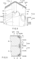
- FIGS. 8 and 9 show a structure of one of the pair of electrode group end surfaces 51A and 51B of each electrode group 2 and their neighboring structure.
- FIG. 8 is a perspective view
- FIG. 9 shows a cross section perpendicular or substantially perpendicular to the height direction of the battery 1. In FIG. 8 , illustration of the container 3 is omitted.
- the positive electrode 13A and the negative electrode 13B are wound, with the winding axis B along the height direction as a center, as described above.
- the electrode group end surfaces 51A and 51B of each of the electrode groups 2 are formed as curved surfaces.
- the electrode group end surfaces 51A and 51B of each of the electrode groups 2 are arcuate or substantially arcuate in a cross section perpendicular or substantially perpendicular to the height direction of the battery 1.
- the spacer 25 includes a pair of protrusions 52A and 52B (first protrusions), a pair of protrusions 53A and 53B (second protrusions), and a pair of protrusions 55A and 55B (third protrusions).
- each of the protrusions 52A, 52B, 53A, 53B, 55A and 55B is more protruding toward the side where the bottom wall 6 is located in the height direction of the battery than the portions other than the protrusions 52A, 52B, 53A, 53B, 55A and 55B.
- the protrusion 52A is formed at the boundary portion between the side plate portions 41A and 42A, and the protrusion 52B is formed at the boundary portion between the side plate portions 41B and 42A.
- the protrusion 53A is formed at the boundary portion between the side plate portions 41A and 42B, and the protrusion 53B is formed at the boundary portion between the side plate portions 41B and 42B.
- the protrusion 55A is formed at the center of the side plate portion 41A in the width direction of the spacer 25 (the depth direction of the battery 1), and the protrusion 55B is formed at the center of the side plate portion 41B in the width direction of the spacer 25.
- the protrusions 52A, 52B, 53A, 53B, 55A, and 55B are formed as described above, the protrusions 52A, 53A and 55A are located apart from the protrusions 52B, 53B and 55B in the lateral direction of the battery 1 in the inner cavity 8.
- the protrusions 52A, 53A and 55A are apart from each other in the depth direction of the battery 1, and the protrusions 52B, 53B and 55B are apart from each other in the depth direction of the battery 1.
- the protrusions 52A and 52B (first protrusions) are located on the side opposite to the electrode group 2B (second electrode group) with respect to the electrode group 2A (first electrode group), in the depth direction of the battery 1.
- the protrusions 53A and 53B are located on the side opposite to the electrode group 2A (first electrode group) with respect to the electrode group 2B (second electrode group), in the depth direction of the battery 1.
- the protrusions 55A and 55B are located between the electrode groups 2A and 2B in the depth direction of the battery 1.
- the protrusion 52A is close to the electrode group 2A from one side in the lateral direction of the battery 1, and the protrusion 52B is close to the electrode group 2A from the side opposite to the protrusion 52A in the lateral direction of the battery 1. Therefore, each of the protrusions 52A and 52B is close to the electrode group 2A from outside the battery 1 in the lateral direction.
- the protrusion 52A is adjacent to the electrode group end surface 51A of the electrode group 2A from outside in the lateral direction
- the protrusion 52B is adjacent to the electrode group end surface 51B of the electrode group 2A from outside in the lateral direction.
- the protrusion 53A is close to the electrode group 2B from one side in the lateral direction of the battery 1, and the protrusion 53B is close to the electrode group 2B from the side opposite to the protrusion 53A in the lateral direction of the battery 1. Therefore, each of the protrusions 53A and 53B is close to the electrode group 2B from outside the battery 1 in the lateral direction.
- the protrusion 53A is adjacent to the electrode group end surface 51A of the electrode group 2B from outside in the lateral direction
- the protrusion 53B is adjacent to the electrode group end surface 51B of the electrode group 2A from outside in the lateral direction.
- the protrusion 55A is close to the electrode groups 2A and 2B from one side in the lateral direction of the battery 1, and the protrusion 55B is close to the electrode groups 2A and 2B from the side opposite to the protrusion 55A in the lateral direction of the battery 1. Therefore, each of the protrusions 55A and 55B is close to the electrode groups 2A and 2B from outside the battery 1 in the lateral direction.
- the protrusion 55A is adjacent to the electrode group end surface 51A of the electrode group 2A and the electrode group end surface 51A of the electrode group 2B from outside in the lateral direction
- the protrusion 52B is adjacent to the electrode group end surface 51B of the electrode group 2A and the electrode group end surface 51B of the electrode group 2B from outside in the lateral direction.
- each of the protrusions 52A, 52B, 55A and 55B is close to the electrode group 2A but is not in contact with the electrode group 2A.
- each of protrusions 53A, 53B, 55A, and 55B is close to electrode group 2B but is not in contact with the electrode group 2B.
- Each of the protrusions 52A and 52B includes a facing surface (inner facing surface) 61 that faces the electrode group 2A and a facing surface (outer facing surface) 62 that faces the peripheral wall 7 of the container 3.
- the facing surface 61 of the protrusion 52A is formed to have a shape along the electrode group end surface 51A of the electrode group 2A, and in the present embodiment, it is formed to have a shape along the curved surface of the electrode group end surface 51A.
- the facing surface 61 of the protrusion 52B is formed to have a shape along the electrode group end surface 51B of the electrode group 2A, and in the present embodiment, it is formed to have a shape along the curved surface of the electrode group end surface 51B.
- the facing surface 62 of each of the protrusions 52A and 52B is formed to have a shape along the inner surface of the peripheral wall 7.
- Each of the protrusions 53A and 53B includes a facing surface (inner facing surface) 63 that faces the electrode group 2B and a facing surface (outer facing surface) 65 that faces the peripheral wall 7 of the container 3.
- the facing surface 63 of the protrusion 53A is formed to have a shape along the electrode group end surface 51A of the electrode group 2B, and in the present embodiment, it is formed to have a shape along the curved surface of the electrode group end surface 51A.
- the facing surface 63 of the protrusion 53B is formed to have a shape along the electrode group end surface 51B of the electrode group 2B, and in the present embodiment, it is formed to have a shape along the curved surface of the electrode group end surface 51B.
- the facing surface 65 is formed to have a shape along the inner surface of the peripheral wall 7.
- Each of the protrusions 55A and 55B includes a facing surface (inner facing surface) 66 that faces the electrode group 2A, a facing surface (inner facing surface) 67 that faces the electrode group 2B, and a facing surface 68 (outer facing surface) that faces the peripheral wall 7 of the container 3.
- the facing surface 66 of the protrusion 55A is formed to have a shape along the electrode group end surface 51A of the electrode group 2A, and in the present embodiment, it is formed to have a shape along the curved surface of the electrode group end surface 51A.
- the facing surface 66 of the protrusion 55B is formed to have a shape along the electrode group end surface 51B of the electrode group 2A, and in the present embodiment, it is formed to have a shape along the curved surface of the electrode group end surface 51B.
- the facing surface 67 of the protrusion 55A is formed to have a shape along the electrode group end surface 51A of the electrode group 2B, and in the present embodiment, it is formed to have a shape along the curved surface of the electrode group end surface 51A.
- the facing surface 67 of the protrusion 55B is formed to have a shape along the electrode group end surface 51B of the electrode group 2B, and in the present embodiment, it is formed to have a shape along the curved surface of the electrode group end surface 51B.
- the facing surface 68 is formed to have a shape along the inner surface of the peripheral wall 7.
- the peripheral plate portion 36 covers the leads 20 and the current collecting tabs 15 from outside in the inner cavity, and the peripheral plate portion 36 comes into contact with the electrode groups 2 from the side where the lid member 5 is located.
- the peripheral plate portion 36 is integrally formed with the top plate portion 35 sandwiched between the leads 20 and the lid member 5. Since the spacer 25 in which the peripheral plate portion 36 is integral with the top plate portion 35 is provided, the internal components to be arranged in the inner cavity 8, including the electrode groups 2, the leads 20 and the spacer 25, and the lid member 5 can be easily assembled with each other. That is, an assembled body in which the internal components to be arranged in the inner cavity 8, the lid member 5, the electrode terminals 16, etc. are assembled can be easily formed. Thus, the workability of forming the assembly during the manufacture the battery 1 is improved.
- the through-holes 45A, 45B, 46A and 46B penetrating the peripheral plate portion 36 are formed.
- the through-holes 45A, 45B, 46A, and 46B are formed in the peripheral plate portion 36, so that even though the top plate portion 35 and the peripheral plate portion 36 are integrally formed, a jig or the like used for joining can be brought into contact with each of the leads 20 through any one or more of the through-holes 45A, 45B, 46A and 46B.
- a jig or the like used for joining can be brought into contact with each of the leads 20 through any one or more of the through-holes 45A, 45B, 46A and 46B.
- each of the through-holes 45A, 45B, 46A and 46B penetrates the peripheral wall along the depth direction of the battery 1.
- the through-holes 45A and 46A overlap each other and also overlap the positive electrode current collecting tabs 15A of the electrode groups 2 and the positive electrode side lead 20A.
- the through-holes 45B and 46B overlap each other and also overlap the negative electrode current collecting tabs 15B of the electrode groups 2 and the negative electrode side lead 20B.
- the through-holes 45A, 45B, 46A and 46B are closed by the insulating tapes 26A and 26B, which are closing members, so that the leads 20, the current collecting tabs 15, etc. are prevented from coming into contact with the peripheral wall 7 of the container 3 through any one of the through-holes 45A, 45B, 46A and 46B. Therefore, the leads 20, the current collecting tabs 15, etc. can be effectively prevented from short-circuiting to the container 3 etc.
- the through-holes 45A, 45B, 46A and 46B are closed, the current collecting tabs 15 etc. are effectively prevented from coming into contact with the container 3 when the above-mentioned assembled body is inserted into the inner cavity 8 of the container 3 during the manufacture of the battery 1. This effectively prevents damage to the current collecting tabs 15 etc. during the manufacture of the battery 1.
- the insulating tape 26A is adhered to the electrode group 2A and the peripheral plate portion 36 and secures the electrode group 2A to the spacer 25.
- the insulating tape 26B is adhered to the electrode group 2B and the peripheral plate portion 36 and secures the electrode group 2B to the spacer 25. Because of this, the lid member 5 and the spacer 25 are effectively prevented from separating from the electrode groups 2 due to the spring property or the like of the current collecting tabs 15, and the internal components to be arranged in the inner cavity 8 and the lid member 5 can be easily assembled with each other.
- each of the protrusions 52A, 52B, 53A, 53B, 55A and 55B of the peripheral plate portion 36 of the spacer 25 protrudes toward the side where the bottom wall is located.
- Each of the protrusions 52A, 52B, 55A and 55B is close to the electrode group 2A from outside the battery 1 in the lateral direction, and the protrusions 52A and 52B have the electrode group 2A interposed with reference to the protrusions 55A and 55B in the depth direction of the battery 1. Therefore, the movement of the electrode group 2A along the depth direction of the battery 1 is restrained by the protrusions 52A, 52B, 55A and 55B.
- the movement of the electrode group 2B along the depth direction of the battery 1 is restrained by the protrusions 53A, 53B, 55A and 55B.
- the movement of the electrode groups 2A and 2B in the depth direction of the battery 1 is restrained, so that in the battery 1, the electrode groups 2A and 2B and the internal components, including the current collecting tabs 15 and the leads 20, are restrained from moving in the depth direction.
- gas may be generated from the electrode groups 2 in the inner cavity 8. Due to the generation of the gas in the inner cavity 8, the container 3 may expand. It should be noted here that in the battery 1, the outer surface area of each side wall 12 is much wider than the outer surface areas of each of the bottom wall 6, the side walls 11 and the lid member 5. Thus, the gas generated in the inner cavity 8 causes each of the side walls 12 to expand outward.
- the internal components such as the electrode groups 2 are restrained from moving in the depth direction of the battery 1, by the protrusions 52A, 52B, 53A, 53B, 55A and 55B. Therefore, even if the side walls 12 expand outward due to the generation of the gas, the protrusions 52A, 52B, 53A, 53B, 55A and 55B restrain the internal components from moving in the depth direction of the battery 1. That is, even if the container 3 expands due to the generation of gas, the internal components are properly restrained. Therefore, even if the gas is generated, the influence which an external impact may have on the internal components, including the electrode groups 2, the current collecting tabs 15 and the leads 20, can be suppressed. Since the influence of the external impact on the internal components can be suppressed, damage to the internal components due to the external impact is prevented, and the durability of the internal components is improved.
- the facing surface 61 of the protrusion 52A and the facing surface 66 of the protrusion 55A are formed to have shapes along the electrode group end surface 51A of the electrode group 2A, and the facing surface 61 of the protrusion 52B and the facing surface 66 of the protrusion 55B are formed to have shapes along the electrode group end surface 51B of the electrode group 2A. Therefore, the movement of the electrode group 2A along the depth direction of the battery 1 is appropriately restrained.
- the facing surface 63 of the protrusion 53A and the facing surface 67 of the protrusion 55A are formed to have shapes along the electrode group end surface 51A of the electrode group 2B, and the facing surface 63 of the protrusion 53B and the facing surface 67 of the protrusion 55B are formed to have shapes along the electrode group end surface 51B of the group 2B. Therefore, the movement of the electrode group 2B along the depth direction of the battery 1 is appropriately restrained.
- each of the protrusions 52A, 52B, 55A and 55B is close to the electrode group 2A, and each of the protrusions 53A, 53B, 55A and 55B is close to the electrode group 2B.
- the spacer 25 is assembled with the electrode groups 2 in such a state that the protrusions 52A, 52B, 53A, 53B, 55A and 55B do not come into contact with any one of the electrode groups 2. Therefore, even though the protrusions 52A, 52B, 53A, 53B, 55A and 55B are provided, the internal components to be arranged in the inner cavity 8 and the lid member 5 can be assembled with each other, with improved workability ensured.
- the peripheral plate portion 36 is integrally formed with the top plate portion 35, so that proper strength of the peripheral plate portion 36 can be ensured even if the peripheral plate portion 36 is made thin.
- the space in the inner cavity 8 can be increased. Since the space in the inner cavity 8 is increased, expansion of the container 3 due to the gas generated in the electrode groups 2 can be reduced.
- the peripheral plate portion 36 is made thin, the space occupied by each of the leads 20 can be increased in the inner cavity 8. Thus, the electrical resistance in the electrical path between each of the electrode terminals 16 and the electrode groups 2 can be reduced.
- Each of the electrode groups 2 need not have a wound structure in which the positive electrode 13A and the negative electrode 13B are wound, with the winding axis B as a center.
- at least one of the electrode groups 2A and 2B may have a stack structure in which a plurality of positive electrodes and a plurality of negative electrodes are alternately stacked.
- the stacking direction of the positive electrodes and the negative electrodes corresponds to the thickness direction
- the electrode group 2 of the stack structure are arranged in the inner cavity 8 in such a state that the stacking direction of the positive electrodes and the negative electrodes corresponds or substantially corresponds to the depth direction of the battery 1.
- the pair of current collecting tabs 15 protrude toward the side where the lid member 5 is located in the height direction of the battery 1 and are located apart from each other in the lateral direction of the battery 1. Also, on the outer surface of the electrode group 2 of the stack structure, each of the outer end portions in the lateral direction of the battery 1 is formed by the corresponding one of the electrode group end surfaces 51A and 51B.
- the facing surface 61 of the protrusion 52A and the facing surface 66 of the protrusion 55A are formed to have shapes along the electrode group end surface 51A of the electrode group 2A, and the facing surface 61 of the protrusion 52B and the facing surface 66 of the protrusion 55B are formed to have shapes along the electrode group end surface 51B of the electrode group 2A. Therefore, the movement of the electrode group 2A along the depth direction of the battery 1 is appropriately restrained, as in the above-described embodiment.
- the facing surface 63 of the protrusion 53A and the facing surface 67 of the protrusion 55A are formed to have shapes along the electrode group end surface 51A of the electrode group 2B
- the facing surface 63 of the protrusion 53B and the facing surface 67 of the protrusion 55B are formed to have shapes along the electrode group end surface 51B of the electrode group 2B.
- the number of electrode groups 2 arranged in the inner cavity 8 is not limited to two, and it suffices that one or more electrode groups 2 are arranged in the inner cavity 8.
- the pair of current collecting tabs 15 of each of the one or more electrode groups 2 protrude toward the side where the lid member 5 is located in the height direction of the battery 1, and are located apart from each other in the lateral direction of the battery 1.
- Each of the current collecting tabs 15 is electrically connected to the corresponding one of the pair of electrode terminals 16, with the corresponding one of the pair of leads 20 being interposed therebetween.
- the top plate portion 35 is sandwiched between the leads 20 and the lid member 5, and in the inner cavity 8, the peripheral plate portion 36 covers the leads 20 and the current collecting tabs 15 from the outer peripheral side.
- the peripheral plate portion 36 contacts the electrode group 2 from the side where the lid member 5 is located, and the spacer 25 including the top plate portion 35 and the peripheral plate portion 36 is integrally formed of an electrically insulating material. Since the top plate portion 35 and the peripheral plate portion 36 are integral with each other, the internal components to be arranged in the inner cavity 8 of the container 3 and the lid member 5 can be easily assembled with each other in each modification, in the same manner as in the above-described embodiment. In each modification, advantages similar to those described above in connection with the above embodiment are obtained.
- the spacer is integrally formed of an electrically insulating material.
- the spacer is provided with the top plate portion sandwiched between the leads and the lid member, and the peripheral plate portion extending from the top plate portion toward the side where the electrode group is located and covering the lead and the current collecting tab in the inner cavity from the outer peripheral side. Accordingly, it is possible to provide a battery in which a current collecting tab protrude toward the side where the lid member is located in the electrode group, and the components to be arranged in the inner cavity of the container and the lid member can be easily assembled with each other.
Landscapes
- Chemical & Material Sciences (AREA)
- Chemical Kinetics & Catalysis (AREA)
- Electrochemistry (AREA)
- General Chemical & Material Sciences (AREA)
- Engineering & Computer Science (AREA)
- Manufacturing & Machinery (AREA)
- Connection Of Batteries Or Terminals (AREA)
- Secondary Cells (AREA)
- Sealing Battery Cases Or Jackets (AREA)
- Cell Separators (AREA)
Abstract
Description
- Embodiments described herein of this invention relate generally to batteries.
- Along with the progress of electronic devices such as mobile phones and personal computers, batteries such as secondary batteries used in the electronic devices are required to be small in size and light in weight. A lithium ion secondary battery is an example of a secondary battery that is reduced in size and weight and that has a high energy density. Meanwhile, secondary batteries such as lead-acid storage batteries and nickel-metal hydride batteries are used as large-sized, high-capacity power sources mounted on vehicles such as electric automobiles, hybrid automobiles, electric motorcycles or forklifts. In recent years, lithium-ion secondary batteries with a high energy density have been developed for use as large-sized, high-capacity power sources to be mounted on vehicles. In the development of lithium-ion secondary batteries to be mounted on vehicles, it is required to realize longer battery life and improved safety, as well as to increase the size and capacity of the batteries.
- As a battery, such as a lithium ion secondary battery, there is a battery in which an electrode group including a positive electrode and a negative electrode is housed in the inner cavity of a container. In this type of battery, the container has a bottom wall and a peripheral wall, and the inner cavity of the container is open in the height direction such that the opening is opposite to the bottom wall. A lid member is attached to the peripheral wall of the container, and the opening of the inner cavity is closed by the lid member. In the battery, electrode terminal is arranged on the outer surface of the lid member in the state where they are exposed to the outside.
- As described above, the battery in which an electrode group is arranged inside the inner cavity of the container includes a battery in which current collecting tab protrudes toward the side where the lid member is located in the electrode group. In the inner cavity of such a battery, a lead is arranged between the electrode group and the lid member in the height direction of the battery, and the electrode terminal is electrically connected to the current collecting tab by means of the lead or the like. In the inner cavity, an electrically insulating spacer covers the lead and current collecting tab from the outer peripheral side. In the battery, the spacer prevents the lead and current collecting tab from coming into contact with the container and electrically isolates the lead and current collecting tab from the container. Further, in the battery, the spacer comes into contact with the electrode group from the side where the lid member is located in the height direction, and restricts the movement of the electrode group along the height direction.
- As described above, in the battery in which the current collecting tab protrudes toward the side where the lid member is located in the electrode group housed in the inner cavity, there is a demand that the components which are arranged in the inner cavity, including the spacer, and the lid member are to be easily assembled with each other.
-
- Patent Literature 1: Jpn. Pat. Appln. KOKAI Publication
2011-070915 - Patent Literature 2: Jpn. Pat. Appln. KOKAI Publication
2011-076852 - The problem to be solved by the present invention is to provide a battery in which the current collecting tab protrudes toward the side where the lid member is located in the electrode group, and the components arranged in the inner cavity of the container and the lid member can be easily assembled with each other.
- According to an embodiment, A battery includes a container, a lid member, an electrode group, a current collecting tab, an electrode terminal, a lead and a spacer. The container includes a bottom wall and a peripheral wall and defines an inner cavity that is open in a height direction toward a side opposite to a side where the bottom wall is located. The lid member is attached to the peripheral wall of the container in a state in which an opening of the inner cavity is closed. The electrode group includes a positive electrode and a negative electrode and is arranged in the inner cavity of the container. The current collecting tab protrudes in the electrode group toward a side where the lid member is located. The electrode terminal is exposed in an outer surface of the lid member. The lead is arranged between the electrode group and the lid member in the inner cavity and electrically connects the current collecting tab and the electrode terminal to each other. The spacer is integrally formed of an electrically insulating material. The spacer includes a top plate portion sandwiched between the lead and the lid member, and a peripheral plate portion extending from the top plate portion toward a side where the electrode group is located and covering the lead and the current collecting tab in the inner cavity from an outer peripheral side. The peripheral plate portion of the spacer comes into contact with the electrode group from a side where the lid member is located.
-
-
FIG. 1 is a perspective view showing each member of a battery according to a first embodiment in an exploded manner. -
FIG. 2 is a perspective view showing the battery according to the first embodiment. -
FIG. 3 is a perspective view showing an assembled body into which components to be arranged in the inner cavity, a lid member, etc. are assembled and which is to be installed in the battery according to the first embodiment. -
FIG. 4 is a perspective view showing a lid member and its neighboring structure in the assembled body shown inFIG. 3 . -
FIG. 5 is a perspective view showing the lid member and its neighboring structure in the assembled body shown inFIG. 3 when they are viewed from a direction different from that ofFIG. 4 . -
FIG. 6 is a perspective view showing a spacer of the battery according to the first embodiment. -
FIG. 7 is a perspective view showing the spacer of the battery according to the first embodiment when it is viewed from a direction different from that shown inFIG. 6 . -
FIG. 8 is a perspective view showing one of a pair of electrode group end surfaces in each of two electrode groups and their neighboring structures in the battery according to the first embodiment. -
FIG. 9 is a cross-sectional view schematically showing one of a pair of electrode group end surfaces in each of the two electrode groups and their neighboring structures in the battery according to the first embodiment in a cross section perpendicular or substantially perpendicular to the height direction of the battery. - A description will now be given of embodiments with reference to the accompanying drawings.
-
FIGS. 1 and2 show abattery 1 according to the first embodiment. As shown inFIGS. 1 and2 , thebattery 1 includes anelectrode group 2, acontainer 3 and alid member 5. Each of thecontainer 3 and thelid member 5 is made of metal, such as aluminum, aluminum alloy, iron, copper or stainless steel. The battery 1 (the container 3) is defined in terms of a depth direction (the direction indicated by arrows X1 and X2), a lateral direction (the direction indicated by arrows Y1 and Y2) intersecting the depth direction (perpendicular or substantially perpendicular thereto), and a height direction (the direction indicated by arrows Z1 and Z2) intersecting both the depth direction and the lateral direction (perpendicular or substantially perpendicular thereto). In each of thebattery 1 and thecontainer 3, the dimension in the depth direction is smaller than the dimension in the lateral direction and the dimension in the height direction.FIG. 1 is a perspective view showing each member of thebattery 1 in an exploded manner, andFIG. 2 is a perspective view. - The
container 3 includes abottom wall 6 andperipheral wall 7. Inside thecontainer 3, aninner cavity 8 in which theelectrode group 2 is housed is defined by thebottom wall 6 and theperipheral wall 7. In the height direction, theinner cavity 8 of thecontainer 3 is open toward the side opposite to the side where thebottom wall 6 is located. Theperipheral wall 7 include two pairs ofside walls side walls 11 are opposed to each other such that theinner cavity 8 is sandwiched in the lateral direction. The pair ofside walls 12 are opposed to each other such that theinner cavity 8 is sandwiched in the depth direction. Each of theside walls 11 continuously extends along the depth direction between theside walls 12. Each of theside walls 12 continuously extends along the lateral direction between theside walls 11. Thelid member 5 is attached to theperipheral wall 7 in an end portion opposite to thebottom wall 6. Therefore, thelid member 5 closes the opening of theinner cavity 8 of thecontainer 3. Thelid member 5 and thebottom wall 6 face each other, with theinner cavity 8 located therebetween in the height direction. - In one example shown in
FIG. 1 etc., twoelectrode groups 2 are arranged in theinner cavity 8. In theinner cavity 8, a plurality of electrode groups 2 (two electrode groups 2) are arranged side by side in the depth direction. One of the twoelectrode groups 2 will be referred to as anelectrode group 2A (first electrode group), and the other one different from theelectrode group 2A will be referred to as anelectrode group 2B (second electrode group). Theelectrode group 2B is arranged adjacent to theelectrode group 2A in the depth direction. Each of theelectrode groups 2 includes apositive electrode 13A and anegative electrode 13B. In each of theelectrode groups 2, a separator (not shown) is interposed between thepositive electrode 13A and thenegative electrode 13B. The separator is formed of an electrically insulating material, and electrically insulates thepositive electrode 13A from thenegative electrode 13B. - The
positive electrode 13A includes a positive electrode current collector, such as a positive electrode current collector foil, and a positive electrode active material-containing layer (not shown) supported on the surface of the positive electrode current collector. The positive electrode current collector is, for example, an aluminum foil, an aluminum alloy foil or the like and has a thickness of about 10 µm to 20 um, but the positive electrode current collector is not limited to this. The positive electrode active material-containing layer includes a positive electrode active material and may optionally include a binder and a conductive agent. Examples of the positive electrode active material are an oxide, a sulfide and a polymer that can occlude and release lithium ions, but the positive electrode active material is not limited to these examples. The positive electrode current collector includes a positive electrodecurrent collecting tab 15A as a portion on which the positive electrode active material-containing layer is not supported. - The
negative electrode 13B includes a negative electrode current collector, such as a negative electrode current collector foil, and a negative electrode active material-containing layer (not shown) supported on the surface of the negative electrode current collector. The negative electrode current collector is, for example, an aluminum foil, an aluminum alloy foil, a copper foil or the like and has a thickness of about 10 µm to 20 µm, but is not limited to this example. The negative electrode active material-containing layer contains a negative electrode active material and may optionally contain a binder and a conductive agent. Examples of the negative electrode active material include a metal oxide, a metal sulfide, a metal nitride and a carbon material that can occlude and release lithium ions, but the negative electrode active material is not limited to these examples. The negative electrode current collector includes a negative electrode current collecting tab 15B as a portion where the negative electrode active material-containing layer is not supported. - In each of the
electrode groups 2 of the example shown inFIG. 1 etc., thepositive electrode 13A, thenegative electrode 13B and the separator are wound, with the winding axis B as a center, in the state where the separator is sandwiched between the positive electrode active material-containing layer and the negative electrode active material-containing layer. In each of theelectrode groups 2, the outermost portion of the wound structure is made of an electrically insulating material. In one example, in each of theelectrode groups 2, the outermost portion of the wound structure is made of a separator. In each of theelectrode groups 2, the positive electrodecurrent collecting tab 15A protrudes from the positive electrode active material-containing layer, the negative electrode active material-containing layer and the separator toward one side in the axial direction (the direction indicated by arrows Z3 and Z4) along the winding axis B. In each of theelectrode groups 2, the negative electrode current collecting tab 15B protrudes from the positive electrode active material-containing layer, the negative electrode active material-containing layer and the separator toward the side where the positive electrodecurrent collecting tab 15A protrudes, in the axial direction along the winding axis B. Therefore, in each of theelectrode groups 2, the pair of current collecting tabs 15 (namely, the positive electrodecurrent collecting tab 15A and the negative electrode current collecting tab 15B) protrude toward the same side in the axial direction along the winding axis B. - Each of the
electrode groups 2 is defined in terms of a width direction (the direction indicated by arrows Y3 and Y4) intersecting (perpendicular or substantially perpendicular to) the axial direction of the winding axis B (the protruding direction of the current collecting tabs 15), and a thickness direction (the direction indicated by arrows X3 and X4) intersecting both the axial direction of the winding axis B and the width direction. In each of theelectrode groups 2, the dimension in the thickness direction is smaller than the dimension in the axial direction and the dimension in the width direction. In other words, each of theelectrode groups 2 is formed having a flat shape. Further, in each of the pair ofcurrent collecting tabs 15 of eachelectrode group 2, a plurality of belt-like portions are bound. - In the present embodiment, each of the
electrode groups 2 is arranged in theinner cavity 8 in the state where the winding axis B is along the height direction of thebattery 1, that is, in the state where the axial direction corresponds or substantially corresponds to the height direction of thebattery 1. In each of theelectrode groups 2, the width direction corresponds or substantially corresponds to the lateral direction of thebattery 1, and the thickness direction corresponds or substantially corresponds to the depth direction of thebattery 1. Each of theelectrode groups 2 is arranged in theinner cavity 8 in a state where a pair ofcurrent collecting tabs 15 protrude toward the side where thelid member 5 is located in the height direction of thebattery 1. In each of theelectrode groups 2, the pair ofcurrent collecting tabs 15 are arranged apart from each other in the lateral direction of thebattery 1. Therefore, in each of theelectrode groups 2, the positive electrodecurrent collecting tab 15A does not come into contact with the negative electrode current collecting tab 15B. - In the
inner cavity 8, each of theelectrode groups 2 holds (is impregnated with) an electrolytic solution (not shown). The electrolytic solution may be a non-aqueous electrolytic solution in which an electrolyte is dissolved in an organic solvent, or an aqueous electrolytic solution such as an aqueous solution. A gel electrolyte may be used instead of the electrolytic solution, or a solid electrolyte may be used. Where a solid electrolyte is used as the electrolyte, the solid electrolyte in each of theelectrode groups 2 is interposed between thepositive electrode 13A and thenegative electrode 13B, in place of the separator. In this case, in each of theelectrode groups 2, the solid electrolyte electrically insulates thepositive electrode 13A from thenegative electrode 13B. - In the
battery 1, a pair ofelectrode terminals 16 are attached to thelid member 5. Theelectrode terminals 16 are made of a conductive material such as metal. One of the pair ofelectrode terminals 16 is a positive terminal (16A) of thebattery 1, and the other one of the pair ofelectrode terminals 16, which is different from the positive terminal (16A), is a negative terminal (16B) of thebattery 1. Each of theelectrode terminals 16 is arranged on the outer surface of thelid member 5 in a state where they are exposed to the outside of thebattery 1. The pair ofelectrode terminals 16 are arranged apart from each other in the lateral direction of thebattery 1. - A pair of through-
holes 17 are formed in thelid member 5, and each of the through-holes 17 penetrates thelid member 5 in the height direction of thebattery 1. On the outer surface of thelid member 5, an insulatingmember 18 is provided between each of theelectrode terminals 16 and thelid member 5. An insulatinggasket 19 is arranged in each of the through-holes 17. Each of theelectrode terminals 16 is electrically insulated from thelid member 5 and thecontainer 3 by the insulatingmember 18 and the insulatinggasket 19. - A pair of
leads 20 and a pair of backup leads 21 are arranged in theinner cavity 8 of thecontainer 3. Each of theleads 20 and the backup leads 21 is made of a conductive material such as metal, and examples of materials forming theleads 20 and the backup leads 21 include aluminum, stainless steel, copper and iron. In theinner cavity 8, theleads 20 are arranged between theelectrode groups 2 and thelid member 5 in the height direction of thebattery 1. - One of the pair of
leads 20 is a positive electrode side lead (20A), and the other one of the pair ofleads 20, which is different from the positive electrode side lead, is a negative electrode side lead (20B). One of the pair of backup leads 21 is a positive electrode side backup lead (21A), and the other one of the pair of backup leads 21, which is different from the positive electrode side backup lead (21A), is a negative electrode side backup lead (21B). The positive electrode side lead 20A and the positive electrodeside backup lead 21A are arranged apart from the negative electrode side lead 20B and the negative electrodeside backup lead 21B in the lateral direction of thebattery 1. Therefore, the positive electrode side lead 20A and the positive electrodeside backup lead 21A do not come into contact with the negative electrode side lead 20B and the negative electrodeside backup lead 21B, respectively. - The positive electrode
current collecting tab 15A of each of theelectrode groups 2 is electrically connected to thepositive terminal 16A, via thebackup lead 21A and thelead 20A in this order. Therefore, thelead 20A forms at least part of an electrical path between the positive electrodecurrent collecting tab 15A and thepositive terminal 16A. The negative electrode current collecting tab 15B of each of theelectrode groups 2 is electrically connected to thenegative terminal 16B, via thebackup lead 21B and the lead 20B in this order. Therefore, the lead 20B forms at least part of an electrical path between the negative electrode current collecting tab 15B and thenegative terminal 16B. - An insulating
tape 23 is attached to each of theelectrode groups 2 from the side where thebottom wall 6 is located in the height direction. The insulatingtape 23 is made of an electrically insulating material. The insulatingtape 23 is closely attached and adhered to each of theelectrode groups 2 in theinner cavity 8 and is sandwiched between each of theelectrode groups 2 and thebottom wall 6 in the height direction of thebattery 1. The two (plurality of)electrode groups 2 are bundled into one by the insulatingtape 23. - A
spacer 25 is incorporated in theinner cavity 8 of thecontainer 3. Thespacer 25 is integrally formed of an electrically insulating material. Thespacer 25 is arranged between theelectrode groups 2 and thelid member 5 in the height direction of thebattery 1. In theinner cavity 8, an insulatingtape 26A is attached to theelectrode group 2A and thespacer 25, and aninsulating tape 26B is attached to theelectrode group 2B and thespacer 25. Each of the insulatingtapes tape 26A is closely attached and adhered to theelectrode group 2A and thespacer 25 and secures theelectrode group 2A to thespacer 25. The insulatingtape 26B is closely attached and adhered to theelectrode group 2B and thespacer 25 and secures theelectrode group 2B to thespacer 25. - The
spacer 25 and the insulatingtapes current collecting tabs 15 of each of theelectrode groups 2, the pair ofleads 20 and the pair of backup leads 21 from coming into contact with thecontainer 3 and thelid member 5. Therefore, thespacer 25 and the insulatingtapes current collecting tabs 15, theleads 20 and the backup leads 21 from thecontainer 3 and thelid member 5. - In one example shown in
FIG. 1 ,FIG. 2 etc., thelid member 5 has agas release valve 27 and aliquid injection port 28. A sealingplate 29 that closes theliquid injection port 28 is welded to the outer surface of thelid member 5. Thegas release valve 27 and theliquid injection port 28 are arranged between theelectrode terminals 16 in the lateral direction of thebattery 1. It should be noted that in one example, thegas release valve 27 and theliquid injection port 28 need not be provided for thebattery 1. - In the
battery 1, the internal components (including theelectrode groups 2, theleads 20 and the spacer 25) to be arranged in theinner cavity 8, thelid member 5, theelectrode terminals 16, etc. are assembled to form an assembled body.FIG. 3 shows an assembled body into which the internal components in theinner cavity 8, thelid member 5 etc. are assembled.FIGS. 4 and5 show thelid member 5 and its neighboring structure in the assembled body shown inFIG. 3 .FIGS. 4 and5 are views of different viewing directions, and illustration of the insulatingtapes - In one example shown in
FIGS. 1 to 5 etc., each of the pair ofleads 20 includes a leadtop plate portion 31 and a leadside plate portion 32. Each of theleads 20 is arranged in theinner cavity 8 in a state where the thickness direction of the leadtop plate portion 31 corresponds or substantially corresponds to the height direction of thebattery 1 and where the thickness direction of the leadside plate portion 32 corresponds or substantially corresponds to the depth direction of thebattery 1. In each of theleads 20, the leadside plate portion 32 is bent with respect to the leadtop plate portion 31 toward the side where the electrode groups 2 (bottom wall 6) are located in the height direction of thebattery 1. In each of theleads 20, the leadside plate portion 32 is connected to one side edge of the leadtop plate portion 31 in the depth direction of thebattery 1. In each of theleads 20, an "L" shape or a substantial "L" shape is formed by the leadtop plate portion 31 and the leadside plate portion 32 in a cross section perpendicular or substantially perpendicular to the lateral direction of thebattery 1. - Each of the
leads 20 has a through-hole 33 that penetrates the leadtop plate portion 31 in the height direction of the battery 1 (in the thickness direction of the lead top plate portion 31). A corresponding one of theelectrode terminals 16 is connected to each of theleads 20 at the through-hole 33. Therefore, in each of theleads 20, the through-hole 33 of the leadtop plate portion 31 serves as a connection position of the corresponding one of theelectrode terminals 16. The corresponding one of theelectrode terminals 16 is connected to each of theleads 20 by caulking or the like. - In one example shown in
FIGS. 1 to 5 etc., the backup leads 21A sandwich the binding portion of the positive electrodecurrent collecting tab 15A of theelectrode group 2A and the binding portion of the positive electrodecurrent collecting tab 15A of theelectrode group 2B. The binding portions of the positive electrodecurrent collecting tabs 15A of the twoelectrode groups 2 are joined to thelead 20A, with thebackup lead 21A interposed therebetween. In thelead 20A, the positive electrodecurrent collecting tabs 15A are joined to the leadside plate portion 32, and the positive electrodecurrent collecting tabs 15A are joined, for example, by ultrasonic welding. Similarly, the backup leads 21B sandwich the binding portion of the negative electrode current collecting tab 15B of theelectrode group 2A and the binding portion of the negative electrode current collecting tab 15B of theelectrode group 2B. The binding portions of the negative electrode current collecting tabs 15B of the twoelectrode groups 2 are joined to the lead 20B, with thebackup lead 21B interposed therebetween. In the lead 20B, the negative electrode current collecting tabs 15B are joined to the leadside plate portion 32, and the negative electrode current collecting tabs 15B are joined, for example, by ultrasonic welding. -
FIGS. 6 and7 show thespacer 25.FIGS. 6 and7 differ from each other in viewing direction. As shown inFIGS. 1 ,6 ,7 etc., thespacer 25 is defined in terms of a length direction (the direction indicated by arrows Y5 and Y6), a width direction (the direction indicated by arrows X5 and X6) intersecting the length direction (perpendicular or substantially perpendicular thereto), and a height direction (the direction indicated by arrows Z5 and Z6) intersecting both the length direction and the width direction (perpendicular or nearly perpendicular thereto). In thespacer 25, the dimension in the length direction is larger than the dimension in the width direction and the dimension in the height direction. Thespacer 25 is arranged in theinner cavity 8 in the state where the height direction thereof corresponds or substantially corresponds to the height direction of thebattery 1 and the width direction thereof corresponds or substantially corresponds to the depth direction of thebattery 1. Therefore, in thespacer 25 arranged in theinner cavity 8, the length direction corresponds or substantially corresponds to the lateral direction of thebattery 1. - The
spacer 25 includes atop plate portion 35 and aperipheral plate portion 36. Thetop plate portion 35 is sandwiched between the leadtop plate portion 31 of each of theleads 20 and thelid member 5 in the height direction of thebattery 1. Thetop plate portion 35 prevents theleads 20 andcurrent collecting tabs 15 from coming into contact with thelid member 5. Thetop plate portion 35 is arranged in theinner cavity 8 in the state where the thickness direction thereof corresponds or substantially corresponds to the height direction of thespacer 25, that is, in the state where the thickness direction thereof corresponds or substantially corresponds to the height direction of thebattery 1. - A pair of through-
holes 37 are formed in thetop plate portion 35 along the height direction of the spacer 25 (the thickness direction of the top plate portion 35). Each of the through-holes 37 penetrates thetop plate portion 35 along the height direction of thebattery 1. The pair of through-holes 37 are arranged apart from each other in the lateral direction of the battery 1 (in the length direction of the spacer 25). Each of theelectrode terminals 16 is inserted through the corresponding one of the through-holes 17 of thelid member 5, the corresponding one of the through-holes 37 of thespacer 25, and the through-hole 33 of the corresponding one of theleads 20, in the order mentioned. Each of theelectrode terminals 16 is connected to the corresponding one of theleads 20 at the through-hole 33, as described above. - The
peripheral plate portion 36 extends from the outer edge of thetop plate portion 35 toward the side where the electrode groups 2 (bottom wall 6) are located in the height direction of thebattery 1. Therefore, theperipheral plate portion 36 protrudes from thetop plate portion 35 toward the side where theelectrode groups 2 are located. Theperipheral plate portion 36 extends along the outer edge of thetop plate portion 35 and is formed over the entire circumference of an outer periphery of thetop plate portion 35. In theinner cavity 8, the two pairs ofcurrent collecting tabs 15 and the one pair ofleads 20 are covered from the outer peripheral side of theinner cavity 8 by theperipheral plate portion 36 of thespacer 25. Theperipheral plate portion 36 covers thecurrent collecting tabs 15 and theleads 20 over the entire circumference of theinner cavity 8 in the circumferential direction. - The
peripheral plate portion 36 includes a pair ofside plate portions side plate portions side plate portions current collecting tabs 15 and theleads 20 being interposed therebetween in the lateral direction of the battery 1 (the length direction of the spacer 25). Therefore, theside plate portion 41A covers thecurrent collecting tabs 15 and theleads 20 from one side in the lateral direction of thebattery 1, and theside plate portion 41B covers thecurrent collecting tabs 15 and theleads 20 from the side opposite to theside plate portion 41A in the lateral direction of thebattery 1. Theside plate portions current collecting tabs 15 and theleads 20 interposed therebetween in the depth direction of the battery 1 (the width direction of the spacer 25). Therefore, theside plate portion 42A covers thecurrent collecting tabs 15 and theleads 20 from one side in the depth direction of thebattery 1, and theside plate portion 42B covers thecurrent collecting tabs 15 and theleads 20 from the side opposite to theside plate portion 42A in the depth direction of thebattery 1. - Each of the
side plate portions battery 1 between theside plate portions side plate portions battery 1 and corresponds or substantially corresponds to the length direction of thespacer 25. Further, each of theside plate portions battery 1 between theside plate portions side plate portions battery 1 and corresponds or substantially corresponds to the width direction of thespacer 25. - In the
inner cavity 8, theperipheral plate portion 36 is located between thetop plate portion 35 of thespacer 25 and theelectrode groups 2, in the height direction of thebattery 1. Theperipheral plate portion 36 of thespacer 25 comes into contact with each of theelectrode groups 2 from the side where thelid member 5 is located in the height direction of thebattery 1. Therefore, each of theelectrode groups 2 is pressed by theperipheral plate portion 36 of thespacer 25 toward the side where thebottom wall 6 is located in the height direction of thebattery 1. Pressed by theperipheral plate portion 36, movement of theelectrode groups 2 along the height direction of thebattery 1 is restricted in theinner cavity 8. In addition, theperipheral plate portion 36 comes into contact with each of theelectrode groups 2 at the protruding end of the protruding portion from thetop plate portion 35 toward the side where theelectrode groups 2 are located. - Through-
holes peripheral plate portion 36 are formed in theperipheral plate portion 36. Each of the through-holes side plate portion 42A and penetrates theside plate portion 42A along the depth direction of thebattery 1. Each of the through-holes side plate portion 42B and penetrates theside plate portion 42B along the depth direction of thebattery 1. The through-holes holes spacer 25 in the lateral direction of thebattery 1 is located between the through-holes holes - The through-
hole 45A is not shifted or is hardly shifted from the through-hole 46A in the lateral direction and the height direction of thebattery 1. Therefore, the through-hole 45A (first through-hole) overlaps the through-hole 46A (second through-hole) when they are projected from the depth direction of thebattery 1. In addition, the through-holes current collecting tabs 15A of theelectrode groups 2 and the positiveelectrode side lead 20A in the lateral direction and the height direction of thebattery 1. Therefore, the through-holes current collecting tabs 15A and thelead 20A when they are projected from the depth direction of thebattery 1. In theinner cavity 8 of thebattery 1, the through-hole 45A (first through-hole) is located on one side in the depth direction with respect to thecurrent collecting tab 15A and thelead 20A. The through-hole 46A (second through-hole) is located on the side opposite to the through-hole 45A in the depth direction of thebattery 1 with respect to thecurrent collecting tab 15A and thelead 20A. - The through-
hole 45B is not shifted or is hardly shifted from the through-hole 46B in the lateral direction and the height direction of thebattery 1. Therefore, the through-hole 45B (first through-hole) overlaps the through-hole 46B (second through-hole) when they are projected from the depth direction of thebattery 1. In addition, the through-holes electrode groups 2 and the negativeelectrode side lead 20B in the lateral direction and the height direction of thebattery 1. Therefore, the through-holes battery 1. In theinner cavity 8 of thebattery 1, the through-hole 45B (first through-hole) is located on one side in the depth direction with respect to the current collecting tab 15B and the lead 20B. The through-hole 46B (second through-hole) is located on the side opposite to the through-hole 45B in the depth direction of thebattery 1 with respect to current collecting tab 15B and the lead 20B. - At the portions of the through-
holes peripheral plate portion 36, the protrusion from thetop plate portion 35 toward the side where theelectrode groups 2 are located is smaller than at portions other than the through-holes peripheral plate portion 36. Therefore, when projected from the depth direction of the battery 1 (the width direction of the spacer 25), the protruding end of theperipheral plate portion 36 is recessed toward the side where the top plate portion 35 (lid member 5) is located at the portions of the through-holes peripheral plate portion 36 contacts each of theelectrode groups 2 at positions different from the through-holes inner cavity 8, and does not contact theelectrode groups 2 at the portions where the through-holes inner cavity 8. - The insulating
tape 26A is attached to theelectrode group 2A and thespacer 25 from one side in the depth direction of thebattery 1. The insulatingtape 26A is closely attached and adhered to theelectrode group 2A from the side opposite to the side where theelectrode group 2B is located. In addition, the insulatingtape 26A is closely attached and adhered to the outer surface of theside plate portion 42A of theperipheral plate portion 36 in thespacer 25. The through-holes side plate portion 42A are closed by the insulatingtape 26A. The insulatingtape 26B is attached to theelectrode group 2B and thespacer 25 from the side opposite to the insulatingtape 26A in the depth direction of thebattery 1. The insulatingtape 26B is closely attached and adhered to theelectrode group 2B from the side opposite to the side where theelectrode group 2A is located. In addition, the insulatingtape 26B is closely attached and adhered to the outer surface of theside plate portion 42B of theperipheral plate portion 36 in thespacer 25. The through-holes side plate portion 42B are closed by the insulatingtape 26B. - Since the through-
holes tapes leads 20 and thecurrent collecting tabs 15 are prevented from coming into contact with theperipheral wall 7 of thecontainer 3 through any one of the through-holes tapes holes electrode groups 2 and theperipheral plate portion 36 of thespacer 25 may be provided in the state where the through-holes - As shown in
FIGS. 3 to 5 etc., each of theelectrode groups 2 includes a pair of electrode group end surfaces 51A and 51B. On the outer surface of each of theelectrode groups 2, the electrode group end surface 51A forms an end portion on one side in the width direction (lateral direction of the battery 1), and the electrodegroup end surface 51B forms an end portion on the opposite side of the electrodegroup end surface 51A in the width direction. Therefore, on the outer surface of each of theelectrode groups 2, each of the outer end portions of thebattery 1 in the lateral direction is formed by the corresponding one of the electrode group end surfaces 51A and 51B.FIGS. 8 and 9 show a structure of one of the pair of electrode group end surfaces 51A and 51B of eachelectrode group 2 and their neighboring structure.FIG. 8 is a perspective view, andFIG. 9 shows a cross section perpendicular or substantially perpendicular to the height direction of thebattery 1. InFIG. 8 , illustration of thecontainer 3 is omitted. - In the present embodiment, in each of the
electrode groups 2, thepositive electrode 13A and thenegative electrode 13B are wound, with the winding axis B along the height direction as a center, as described above. As shown inFIGS. 3 ,8, 9 etc., the electrode group end surfaces 51A and 51B of each of theelectrode groups 2 are formed as curved surfaces. In the present embodiment, the electrode group end surfaces 51A and 51B of each of theelectrode groups 2 are arcuate or substantially arcuate in a cross section perpendicular or substantially perpendicular to the height direction of thebattery 1. - As shown in
FIGS. 3 to 9 etc., thespacer 25 includes a pair ofprotrusions protrusions protrusions peripheral plate portion 36 of thespacer 25, each of theprotrusions bottom wall 6 is located in the height direction of the battery than the portions other than theprotrusions peripheral plate portion 36 of thespacer 25, theprotrusion 52A is formed at the boundary portion between theside plate portions protrusion 52B is formed at the boundary portion between theside plate portions peripheral plate portion 36, theprotrusion 53A is formed at the boundary portion between theside plate portions protrusion 53B is formed at the boundary portion between theside plate portions peripheral plate portion 36, theprotrusion 55A is formed at the center of theside plate portion 41A in the width direction of the spacer 25 (the depth direction of the battery 1), and theprotrusion 55B is formed at the center of theside plate portion 41B in the width direction of thespacer 25. - Since the
protrusions protrusions protrusions battery 1 in theinner cavity 8. Theprotrusions battery 1, and theprotrusions battery 1. Theprotrusions electrode group 2B (second electrode group) with respect to theelectrode group 2A (first electrode group), in the depth direction of thebattery 1. Theprotrusions electrode group 2A (first electrode group) with respect to theelectrode group 2B (second electrode group), in the depth direction of thebattery 1. Theprotrusions electrode groups battery 1. - The
protrusion 52A is close to theelectrode group 2A from one side in the lateral direction of thebattery 1, and theprotrusion 52B is close to theelectrode group 2A from the side opposite to theprotrusion 52A in the lateral direction of thebattery 1. Therefore, each of theprotrusions electrode group 2A from outside thebattery 1 in the lateral direction. Theprotrusion 52A is adjacent to the electrodegroup end surface 51A of theelectrode group 2A from outside in the lateral direction, and theprotrusion 52B is adjacent to the electrodegroup end surface 51B of theelectrode group 2A from outside in the lateral direction. Moreover, theprotrusion 53A is close to theelectrode group 2B from one side in the lateral direction of thebattery 1, and theprotrusion 53B is close to theelectrode group 2B from the side opposite to theprotrusion 53A in the lateral direction of thebattery 1. Therefore, each of theprotrusions electrode group 2B from outside thebattery 1 in the lateral direction. Theprotrusion 53A is adjacent to the electrodegroup end surface 51A of theelectrode group 2B from outside in the lateral direction, and theprotrusion 53B is adjacent to the electrodegroup end surface 51B of theelectrode group 2A from outside in the lateral direction. - The
protrusion 55A is close to theelectrode groups battery 1, and theprotrusion 55B is close to theelectrode groups protrusion 55A in the lateral direction of thebattery 1. Therefore, each of theprotrusions electrode groups battery 1 in the lateral direction. Theprotrusion 55A is adjacent to the electrodegroup end surface 51A of theelectrode group 2A and the electrodegroup end surface 51A of theelectrode group 2B from outside in the lateral direction, and theprotrusion 52B is adjacent to the electrodegroup end surface 51B of theelectrode group 2A and the electrodegroup end surface 51B of theelectrode group 2B from outside in the lateral direction. Each of theprotrusions electrode group 2A but is not in contact with theelectrode group 2A. Similarly, each of protrusions 53A, 53B, 55A, and 55B is close toelectrode group 2B but is not in contact with theelectrode group 2B. - Each of the
protrusions electrode group 2A and a facing surface (outer facing surface) 62 that faces theperipheral wall 7 of thecontainer 3. The facingsurface 61 of theprotrusion 52A is formed to have a shape along the electrodegroup end surface 51A of theelectrode group 2A, and in the present embodiment, it is formed to have a shape along the curved surface of the electrodegroup end surface 51A. Further, the facingsurface 61 of theprotrusion 52B is formed to have a shape along the electrodegroup end surface 51B of theelectrode group 2A, and in the present embodiment, it is formed to have a shape along the curved surface of the electrodegroup end surface 51B. The facingsurface 62 of each of theprotrusions peripheral wall 7. - Each of the
protrusions electrode group 2B and a facing surface (outer facing surface) 65 that faces theperipheral wall 7 of thecontainer 3. The facingsurface 63 of theprotrusion 53A is formed to have a shape along the electrodegroup end surface 51A of theelectrode group 2B, and in the present embodiment, it is formed to have a shape along the curved surface of the electrodegroup end surface 51A. Further, the facingsurface 63 of theprotrusion 53B is formed to have a shape along the electrodegroup end surface 51B of theelectrode group 2B, and in the present embodiment, it is formed to have a shape along the curved surface of the electrodegroup end surface 51B. In each of theprotrusions surface 65 is formed to have a shape along the inner surface of theperipheral wall 7. - Each of the
protrusions electrode group 2A, a facing surface (inner facing surface) 67 that faces theelectrode group 2B, and a facing surface 68 (outer facing surface) that faces theperipheral wall 7 of thecontainer 3. The facingsurface 66 of theprotrusion 55A is formed to have a shape along the electrodegroup end surface 51A of theelectrode group 2A, and in the present embodiment, it is formed to have a shape along the curved surface of the electrodegroup end surface 51A. Further, the facingsurface 66 of theprotrusion 55B is formed to have a shape along the electrodegroup end surface 51B of theelectrode group 2A, and in the present embodiment, it is formed to have a shape along the curved surface of the electrodegroup end surface 51B. The facingsurface 67 of theprotrusion 55A is formed to have a shape along the electrodegroup end surface 51A of theelectrode group 2B, and in the present embodiment, it is formed to have a shape along the curved surface of the electrodegroup end surface 51A. Further, the facingsurface 67 of theprotrusion 55B is formed to have a shape along the electrodegroup end surface 51B of theelectrode group 2B, and in the present embodiment, it is formed to have a shape along the curved surface of the electrodegroup end surface 51B. In each of theprotrusions surface 68 is formed to have a shape along the inner surface of theperipheral wall 7. - As described above, in the present embodiment, the
peripheral plate portion 36 covers theleads 20 and thecurrent collecting tabs 15 from outside in the inner cavity, and theperipheral plate portion 36 comes into contact with theelectrode groups 2 from the side where thelid member 5 is located. Theperipheral plate portion 36 is integrally formed with thetop plate portion 35 sandwiched between theleads 20 and thelid member 5. Since thespacer 25 in which theperipheral plate portion 36 is integral with thetop plate portion 35 is provided, the internal components to be arranged in theinner cavity 8, including theelectrode groups 2, theleads 20 and thespacer 25, and thelid member 5 can be easily assembled with each other. That is, an assembled body in which the internal components to be arranged in theinner cavity 8, thelid member 5, theelectrode terminals 16, etc. are assembled can be easily formed. Thus, the workability of forming the assembly during the manufacture thebattery 1 is improved. - In the
spacer 25 of the present embodiment, the through-holes peripheral plate portion 36 are formed. When the above-mentioned assembled body is formed during the manufacture of thebattery 1, each of theelectrode terminals 16 is connected to the corresponding one of theleads 20 in the state where thetop plate portion 35 of thespacer 25 is sandwiched between each of theleads 20 and thelid member 5. Then, each of thecurrent collecting tabs 15 is joined to the corresponding one of the leads 20. In the present embodiment, the through-holes peripheral plate portion 36, so that even though thetop plate portion 35 and theperipheral plate portion 36 are integrally formed, a jig or the like used for joining can be brought into contact with each of theleads 20 through any one or more of the through-holes top plate portion 35 and theperipheral plate portion 36 are integrally formed, improved workability is ensured in the operation of joining each of thecurrent collecting tabs 15 to the corresponding one of the leads 20. - In the present embodiment, each of the through-
holes battery 1. When projected from the depth direction of thebattery 1, the through-holes current collecting tabs 15A of theelectrode groups 2 and the positive electrode side lead 20A. In addition, when projected from the depth direction of thebattery 1, the through-holes electrode groups 2 and the negative electrode side lead 20B. For this reason, improved workability is ensured in the operation of connecting each of the positive electrodecurrent collecting tabs 15A of theelectrode groups 2 to the positive electrode side lead 20A and the operation of connecting each of the negative electrode current collecting tabs 15B of theelectrode groups 2 to the negative electrode side lead 20B. - In the present embodiment, the through-
holes tapes current collecting tabs 15, etc. are prevented from coming into contact with theperipheral wall 7 of thecontainer 3 through any one of the through-holes leads 20, thecurrent collecting tabs 15, etc. can be effectively prevented from short-circuiting to thecontainer 3 etc. In addition, since the through-holes current collecting tabs 15 etc. are effectively prevented from coming into contact with thecontainer 3 when the above-mentioned assembled body is inserted into theinner cavity 8 of thecontainer 3 during the manufacture of thebattery 1. This effectively prevents damage to thecurrent collecting tabs 15 etc. during the manufacture of thebattery 1. - In the present embodiment, the insulating
tape 26A is adhered to theelectrode group 2A and theperipheral plate portion 36 and secures theelectrode group 2A to thespacer 25. The insulatingtape 26B is adhered to theelectrode group 2B and theperipheral plate portion 36 and secures theelectrode group 2B to thespacer 25. Because of this, thelid member 5 and thespacer 25 are effectively prevented from separating from theelectrode groups 2 due to the spring property or the like of thecurrent collecting tabs 15, and the internal components to be arranged in theinner cavity 8 and thelid member 5 can be easily assembled with each other. - In the present embodiment, each of the
protrusions peripheral plate portion 36 of thespacer 25 protrudes toward the side where the bottom wall is located. Each of theprotrusions electrode group 2A from outside thebattery 1 in the lateral direction, and theprotrusions electrode group 2A interposed with reference to theprotrusions battery 1. Therefore, the movement of theelectrode group 2A along the depth direction of thebattery 1 is restrained by theprotrusions electrode group 2B along the depth direction of thebattery 1 is restrained by theprotrusions electrode groups battery 1 is restrained, so that in thebattery 1, theelectrode groups current collecting tabs 15 and theleads 20, are restrained from moving in the depth direction. - When the
battery 1 is used, gas may be generated from theelectrode groups 2 in theinner cavity 8. Due to the generation of the gas in theinner cavity 8, thecontainer 3 may expand. It should be noted here that in thebattery 1, the outer surface area of eachside wall 12 is much wider than the outer surface areas of each of thebottom wall 6, theside walls 11 and thelid member 5. Thus, the gas generated in theinner cavity 8 causes each of theside walls 12 to expand outward. - As described above, in the present embodiment, the internal components, such as the
electrode groups 2, are restrained from moving in the depth direction of thebattery 1, by theprotrusions side walls 12 expand outward due to the generation of the gas, theprotrusions battery 1. That is, even if thecontainer 3 expands due to the generation of gas, the internal components are properly restrained. Therefore, even if the gas is generated, the influence which an external impact may have on the internal components, including theelectrode groups 2, thecurrent collecting tabs 15 and theleads 20, can be suppressed. Since the influence of the external impact on the internal components can be suppressed, damage to the internal components due to the external impact is prevented, and the durability of the internal components is improved. - In the present embodiment, the facing
surface 61 of theprotrusion 52A and the facingsurface 66 of theprotrusion 55A are formed to have shapes along the electrodegroup end surface 51A of theelectrode group 2A, and the facingsurface 61 of theprotrusion 52B and the facingsurface 66 of theprotrusion 55B are formed to have shapes along the electrodegroup end surface 51B of theelectrode group 2A. Therefore, the movement of theelectrode group 2A along the depth direction of thebattery 1 is appropriately restrained. Similarly, the facingsurface 63 of theprotrusion 53A and the facingsurface 67 of theprotrusion 55A are formed to have shapes along the electrodegroup end surface 51A of theelectrode group 2B, and the facingsurface 63 of theprotrusion 53B and the facingsurface 67 of theprotrusion 55B are formed to have shapes along the electrodegroup end surface 51B of thegroup 2B. Therefore, the movement of theelectrode group 2B along the depth direction of thebattery 1 is appropriately restrained. - In the assembled body described above, each of the
protrusions electrode group 2A, and each of theprotrusions electrode group 2B. It should be noted, however, that thespacer 25 is assembled with theelectrode groups 2 in such a state that theprotrusions electrode groups 2. Therefore, even though theprotrusions inner cavity 8 and thelid member 5 can be assembled with each other, with improved workability ensured. - In the present embodiment, the
peripheral plate portion 36 is integrally formed with thetop plate portion 35, so that proper strength of theperipheral plate portion 36 can be ensured even if theperipheral plate portion 36 is made thin. By using such a thinperipheral plate portion 36, the space in theinner cavity 8 can be increased. Since the space in theinner cavity 8 is increased, expansion of thecontainer 3 due to the gas generated in theelectrode groups 2 can be reduced. In addition, since theperipheral plate portion 36 is made thin, the space occupied by each of theleads 20 can be increased in theinner cavity 8. Thus, the electrical resistance in the electrical path between each of theelectrode terminals 16 and theelectrode groups 2 can be reduced. - Each of the
electrode groups 2 need not have a wound structure in which thepositive electrode 13A and thenegative electrode 13B are wound, with the winding axis B as a center. In one modification, at least one of theelectrode groups electrode group 2 of the stack structure, the stacking direction of the positive electrodes and the negative electrodes corresponds to the thickness direction, and theelectrode group 2 of the stack structure are arranged in theinner cavity 8 in such a state that the stacking direction of the positive electrodes and the negative electrodes corresponds or substantially corresponds to the depth direction of thebattery 1. In theelectrode group 2 of the stack structure as well, the pair ofcurrent collecting tabs 15 protrude toward the side where thelid member 5 is located in the height direction of thebattery 1 and are located apart from each other in the lateral direction of thebattery 1. Also, on the outer surface of theelectrode group 2 of the stack structure, each of the outer end portions in the lateral direction of thebattery 1 is formed by the corresponding one of the electrode group end surfaces 51A and 51B. - Even where the
electrode group 2A is formed to have a stack structure, the facingsurface 61 of theprotrusion 52A and the facingsurface 66 of theprotrusion 55A are formed to have shapes along the electrodegroup end surface 51A of theelectrode group 2A, and the facingsurface 61 of theprotrusion 52B and the facingsurface 66 of theprotrusion 55B are formed to have shapes along the electrodegroup end surface 51B of theelectrode group 2A. Therefore, the movement of theelectrode group 2A along the depth direction of thebattery 1 is appropriately restrained, as in the above-described embodiment. Where theelectrode group 2B is also formed to have a stack structure, the facingsurface 63 of theprotrusion 53A and the facingsurface 67 of theprotrusion 55A are formed to have shapes along the electrodegroup end surface 51A of theelectrode group 2B, and the facingsurface 63 of theprotrusion 53B and the facingsurface 67 of theprotrusion 55B are formed to have shapes along the electrodegroup end surface 51B of theelectrode group 2B. Thus, the movement of theelectrode group 2B along the depth direction of thebattery 1 is appropriately restrained, as in the above-described embodiment. Therefore, even where at least one of theelectrode groups - The number of
electrode groups 2 arranged in theinner cavity 8 is not limited to two, and it suffices that one ormore electrode groups 2 are arranged in theinner cavity 8. In each modification, however, the pair ofcurrent collecting tabs 15 of each of the one ormore electrode groups 2 protrude toward the side where thelid member 5 is located in the height direction of thebattery 1, and are located apart from each other in the lateral direction of thebattery 1. Each of thecurrent collecting tabs 15 is electrically connected to the corresponding one of the pair ofelectrode terminals 16, with the corresponding one of the pair ofleads 20 being interposed therebetween. - In each modification, the
top plate portion 35 is sandwiched between theleads 20 and thelid member 5, and in theinner cavity 8, theperipheral plate portion 36 covers theleads 20 and thecurrent collecting tabs 15 from the outer peripheral side. Theperipheral plate portion 36 contacts theelectrode group 2 from the side where thelid member 5 is located, and thespacer 25 including thetop plate portion 35 and theperipheral plate portion 36 is integrally formed of an electrically insulating material. Since thetop plate portion 35 and theperipheral plate portion 36 are integral with each other, the internal components to be arranged in theinner cavity 8 of thecontainer 3 and thelid member 5 can be easily assembled with each other in each modification, in the same manner as in the above-described embodiment. In each modification, advantages similar to those described above in connection with the above embodiment are obtained. - According to at least one of the embodiments or examples, the spacer is integrally formed of an electrically insulating material. The spacer is provided with the top plate portion sandwiched between the leads and the lid member, and the peripheral plate portion extending from the top plate portion toward the side where the electrode group is located and covering the lead and the current collecting tab in the inner cavity from the outer peripheral side. Accordingly, it is possible to provide a battery in which a current collecting tab protrude toward the side where the lid member is located in the electrode group, and the components to be arranged in the inner cavity of the container and the lid member can be easily assembled with each other.
- Although some embodiments of the invention have been described, these embodiments are for purposes of illustration and are not intended to limit the scope of the invention. These novel embodiments may be implemented in various other forms and may be omitted, substituted, or changed in various ways without departing from the gist of the invention. These embodiments and modifications thereof are included in the scope and gist of the invention and are included in the invention disclosed in the claims and the equivalent scope thereof.
Claims (10)
- A battery comprising:a container including a bottom wall and a peripheral wall and defining an inner cavity that is open in a height direction toward a side opposite to a side where the bottom wall is located;a lid member attached to the peripheral wall of the container in a state in which an opening of the inner cavity is closed;an electrode group including a positive electrode and a negative electrode and arranged in the inner cavity of the container;a current collecting tab protruding in the electrode group toward a side where the lid member is located;an electrode terminal exposed in an outer surface of the lid member;a lead arranged between the electrode group and the lid member in the inner cavity and electrically connecting the current collecting tab and the electrode terminal to each other; anda spacer integrally formed of an electrically insulating material, the spacer including a top plate portion sandwiched between the lead and the lid member, and a peripheral plate portion extending from the top plate portion toward a side where the electrode group is located and covering the lead and the current collecting tab in the inner cavity from an outer peripheral side, the peripheral plate portion coming into contact with the electrode group from a side where the lid member is located.
- The battery according to claim 1, wherein
the peripheral plate portion of the spacer has a through-hole formed through the peripheral plate portion. - The battery according to claim 2, whereinthe through-hole penetrates the peripheral plate portion along a depth direction intersecting the height direction, andthe through-hole overlaps the current collecting tab and the lead in a projection from the depth direction.
- The battery according to claim 2 or 3, whereinthe peripheral plate portion has a first through-hole and a second through-hole formed as the through-hole,the first through-hole overlaps the second through-hole in a projection from a depth direction intersecting the height direction,the first through-hole is located on one side in the depth direction with respect to the current collecting tab and the lead, andthe second through-hole is located on a side opposite to the first through-hole in the depth direction with respect to the current collecting tab and the lead.
- The battery according to any one of claims 2 to 4, further comprising:
a closing member made of an electrically insulating material and attached to the electrode group and the peripheral plate portion of the spacer in a state where the through-hole of the peripheral plate portion is closed. - The battery according to any one of claims 1 to 5, whereinthe spacer includes a protrusion protruding in the peripheral plate portion toward a side where the bottom wall is located in the height direction, andwhere a depth direction intersecting the height direction and a lateral direction intersecting both the height direction and the depth direction are defined, the protrusion of the spacer is close to the electrode group from outside in the lateral direction.
- The battery according to claim 6, whereinthe protrusion includes a facing surface facing the electrode group from outside in the lateral direction,the electrode group includes an electrode group end surface forming an outer end portion of an outer surface in the lateral direction, andthe facing surface of the protrusion is formed to have a shape along the electrode group end surface.
- The battery according to claim 7, whereinin the electrode group, the positive electrode and the negative electrode are wound, with a winding axis along the height direction as a center,the electrode group end surface of the electrode group is formed as a curved surface that is arcuate in a cross section perpendicular to the height direction, andthe facing surface of the protrusion is formed to have a shape along the curved surface of the electrode group end surface of the electrode group.
- The battery according to any one of claims 6 to 8, whereina plural of the electrode group are arranged in the inner cavity,the plurality of electrode groups includes a first electrode group and a second electrode group arranged adjacent to the first electrode group in the depth direction, andthe protrusion of the spacer includes:a first protrusion located on a side opposite to the second electrode group in the depth direction with respect to the first electrode group, and being close to the first electrode group from outside in the lateral direction;a second protrusion located on a side opposite to the first electrode group in the depth direction with respect to the second electrode group, and being close to the second electrode group from outside in the lateral direction; anda third protrusion located between the first electrode group and the second electrode group in the depth direction, and being close to the first electrode group and the second electrode group from outside in the lateral direction.
- The battery according to any one of claims 1 to 9, whereinthe electrode terminal includes a positive terminal, and a negative terminal arranged on the outer surface of the lid member at a position away from the positive terminal,the current collecting tab includes a positive electrode current collecting tab that protrudes in the electrode group toward a side where the lid member is located, and a negative electrode current collecting tab provided away from the positive electrode current collecting tab and protruding in the electrode group toward a side where the positive electrode current collecting tab protrudes, andthe lead includes a positive electrode side lead that electrically connects the positive terminal and the positive electrode current collecting tab to each other, and a negative electrode side lead that electrically connects the negative terminal and the negative electrode current collecting tab to each other.
Applications Claiming Priority (1)
| Application Number | Priority Date | Filing Date | Title |
|---|---|---|---|
| PCT/JP2020/046525 WO2022130450A1 (en) | 2020-12-14 | 2020-12-14 | Battery |
Publications (2)
| Publication Number | Publication Date |
|---|---|
| EP4261963A1 true EP4261963A1 (en) | 2023-10-18 |
| EP4261963A4 EP4261963A4 (en) | 2024-10-09 |
Family
ID=82057372
Family Applications (1)
| Application Number | Title | Priority Date | Filing Date |
|---|---|---|---|
| EP20965838.4A Withdrawn EP4261963A4 (en) | 2020-12-14 | 2020-12-14 | BATTERY |
Country Status (5)
| Country | Link |
|---|---|
| US (1) | US20230223657A1 (en) |
| EP (1) | EP4261963A4 (en) |
| JP (1) | JP7472317B2 (en) |
| KR (1) | KR102843507B1 (en) |
| WO (1) | WO2022130450A1 (en) |
Cited By (1)
| Publication number | Priority date | Publication date | Assignee | Title |
|---|---|---|---|---|
| EP4148898A4 (en) * | 2021-07-20 | 2024-09-04 | Contemporary Amperex Technology Co., Limited | BATTERY ELEMENT, BATTERY, ELECTRICAL DEVICE, AND METHOD AND DEVICE FOR MANUFACTURING BATTERY ELEMENT |
Families Citing this family (10)
| Publication number | Priority date | Publication date | Assignee | Title |
|---|---|---|---|---|
| WO2023245673A1 (en) * | 2022-06-24 | 2023-12-28 | 宁德时代新能源科技股份有限公司 | Battery cell, battery and electric device |
| CN117438749A (en) * | 2022-07-14 | 2024-01-23 | 宁德时代新能源科技股份有限公司 | Battery monomer, battery and power consumption device |
| US20240170808A1 (en) * | 2022-11-23 | 2024-05-23 | Sk On Co., Ltd. | Battery cell including current collecting structure and battery device including the same |
| JP1775610S (en) * | 2023-03-03 | 2024-07-17 | Battery, Electric | |
| EP4597678A4 (en) * | 2023-03-03 | 2026-01-07 | Contemporary Amperex Technology Hong Kong Ltd | BATTERY CELL, BATTERY AND ELECTRICAL DEVICE |
| CN221353125U (en) * | 2023-09-28 | 2024-07-16 | 湖北亿纬动力有限公司 | Battery, battery module and car |
| EP4723264A1 (en) * | 2023-05-31 | 2026-04-08 | Panasonic Intellectual Property Management Co., Ltd. | Power storage device |
| JP1778256S (en) * | 2023-08-23 | 2024-08-21 | Battery, Electric | |
| JP2025040222A (en) * | 2023-09-11 | 2025-03-24 | プライムプラネットエナジー&ソリューションズ株式会社 | Secondary battery |
| KR20260022661A (en) * | 2024-08-08 | 2026-02-20 | 삼성에스디아이 주식회사 | Cap assembly and secondary battery including same |
Family Cites Families (9)
| Publication number | Priority date | Publication date | Assignee | Title |
|---|---|---|---|---|
| JP5443922B2 (en) | 2009-09-25 | 2014-03-19 | 株式会社東芝 | Non-aqueous electrolyte battery |
| JP2011076952A (en) | 2009-09-30 | 2011-04-14 | Toshiba Corp | Sealed battery |
| JP5517148B2 (en) | 2009-09-30 | 2014-06-11 | 東レ・デュポン株式会社 | Conductor and electric wire using the same |
| US20120052341A1 (en) * | 2010-09-01 | 2012-03-01 | Duk-Jung Kim | Rechargeable battery |
| EP3229305B1 (en) | 2014-12-04 | 2019-05-08 | Hitachi Automotive Systems, Ltd. | Rectangular secondary battery |
| DE112016003986T5 (en) * | 2015-09-01 | 2018-05-30 | Kabushiki Kaisha Toyota Jidoshokki | ELECTRICITY STORAGE DEVICE |
| JP6677106B2 (en) * | 2016-06-30 | 2020-04-08 | 株式会社豊田自動織機 | Power storage device |
| CN111162205B (en) * | 2018-11-07 | 2024-10-18 | 宁德时代新能源科技股份有限公司 | Secondary battery and method for manufacturing secondary battery |
| CN211530012U (en) * | 2019-12-30 | 2020-09-18 | 蜂巢能源科技有限公司 | Battery core, module and power battery pack |
-
2020
- 2020-12-14 JP JP2022569327A patent/JP7472317B2/en active Active
- 2020-12-14 EP EP20965838.4A patent/EP4261963A4/en not_active Withdrawn
- 2020-12-14 WO PCT/JP2020/046525 patent/WO2022130450A1/en not_active Ceased
- 2020-12-14 KR KR1020237006417A patent/KR102843507B1/en active Active
-
2023
- 2023-03-15 US US18/184,081 patent/US20230223657A1/en active Pending
Cited By (2)
| Publication number | Priority date | Publication date | Assignee | Title |
|---|---|---|---|---|
| EP4148898A4 (en) * | 2021-07-20 | 2024-09-04 | Contemporary Amperex Technology Co., Limited | BATTERY ELEMENT, BATTERY, ELECTRICAL DEVICE, AND METHOD AND DEVICE FOR MANUFACTURING BATTERY ELEMENT |
| US12176582B2 (en) | 2021-07-20 | 2024-12-24 | Contemporary Amperex Technology (Hong Kong) Limited | Battery cell, battery, electrical device, and method and device for manufacturing battery cell |
Also Published As
| Publication number | Publication date |
|---|---|
| JP7472317B2 (en) | 2024-04-22 |
| EP4261963A4 (en) | 2024-10-09 |
| WO2022130450A1 (en) | 2022-06-23 |
| KR102843507B1 (en) | 2025-08-08 |
| KR20230042347A (en) | 2023-03-28 |
| US20230223657A1 (en) | 2023-07-13 |
| JPWO2022130450A1 (en) | 2022-06-23 |
Similar Documents
| Publication | Publication Date | Title |
|---|---|---|
| US20230223657A1 (en) | Battery | |
| US8673470B2 (en) | Secondary cell | |
| EP3109926B1 (en) | Rechargeable battery and rechargeable battery module | |
| US7981540B2 (en) | Rechargeable battery | |
| CN111406338B (en) | Electrode assembly and secondary battery including the electrode assembly | |
| US20220223984A1 (en) | Rechargeable battery | |
| US12230841B2 (en) | Battery | |
| US20230223586A1 (en) | Battery | |
| CN111971840A (en) | Electrode assembly and secondary battery including the same | |
| EP2424007B1 (en) | Rechargeable battery | |
| CN118382955A (en) | Secondary battery | |
| CN120511374A (en) | Electrode assembly and cylindrical secondary battery including the same | |
| KR101121205B1 (en) | Secondary battery | |
| JP2006080066A (en) | Lithium ion secondary battery | |
| KR100696784B1 (en) | Cylindrical Lithium Secondary Battery and Manufacturing Method Thereof | |
| CN216213948U (en) | Battery | |
| CN116830379A (en) | Storage element | |
| WO2022123680A1 (en) | Battery | |
| JP7800729B2 (en) | battery | |
| JP7600422B2 (en) | battery | |
| US20250149740A1 (en) | Secondary battery | |
| JP2026053862A (en) | secondary battery | |
| JP2024131678A (en) | Secondary battery | |
| WO2026069741A1 (en) | Secondary battery | |
| CN120432828A (en) | Rechargeable batteries |
Legal Events
| Date | Code | Title | Description |
|---|---|---|---|
| STAA | Information on the status of an ep patent application or granted ep patent |
Free format text: STATUS: THE INTERNATIONAL PUBLICATION HAS BEEN MADE |
|
| PUAI | Public reference made under article 153(3) epc to a published international application that has entered the european phase |
Free format text: ORIGINAL CODE: 0009012 |
|
| STAA | Information on the status of an ep patent application or granted ep patent |
Free format text: STATUS: REQUEST FOR EXAMINATION WAS MADE |
|
| 17P | Request for examination filed |
Effective date: 20230314 |
|
| AK | Designated contracting states |
Kind code of ref document: A1 Designated state(s): AL AT BE BG CH CY CZ DE DK EE ES FI FR GB GR HR HU IE IS IT LI LT LU LV MC MK MT NL NO PL PT RO RS SE SI SK SM TR |
|
| DAV | Request for validation of the european patent (deleted) | ||
| DAX | Request for extension of the european patent (deleted) | ||
| REG | Reference to a national code |
Ref country code: DE Ref legal event code: R079 Free format text: PREVIOUS MAIN CLASS: H01M0010040000 Ipc: H01M0050147000 |
|
| A4 | Supplementary search report drawn up and despatched |
Effective date: 20240910 |
|
| RIC1 | Information provided on ipc code assigned before grant |
Ipc: H01M 50/474 20210101ALI20240904BHEP Ipc: H01M 50/593 20210101ALI20240904BHEP Ipc: H01M 50/553 20210101ALI20240904BHEP Ipc: H01M 50/55 20210101ALI20240904BHEP Ipc: H01M 50/538 20210101ALI20240904BHEP Ipc: H01M 50/533 20210101ALI20240904BHEP Ipc: H01M 50/531 20210101ALI20240904BHEP Ipc: H01M 50/528 20210101ALI20240904BHEP Ipc: H01M 50/176 20210101ALI20240904BHEP Ipc: H01M 50/169 20210101ALI20240904BHEP Ipc: H01M 50/15 20210101ALI20240904BHEP Ipc: H01M 50/103 20210101ALI20240904BHEP Ipc: H01M 10/0587 20100101ALI20240904BHEP Ipc: H01M 50/477 20210101ALI20240904BHEP Ipc: H01M 50/147 20210101AFI20240904BHEP |
|
| STAA | Information on the status of an ep patent application or granted ep patent |
Free format text: STATUS: THE APPLICATION IS DEEMED TO BE WITHDRAWN |
|
| 18D | Application deemed to be withdrawn |
Effective date: 20250328 |