EP4261960A1 - Onboard fuel cell system - Google Patents
Onboard fuel cell system Download PDFInfo
- Publication number
- EP4261960A1 EP4261960A1 EP20964992.0A EP20964992A EP4261960A1 EP 4261960 A1 EP4261960 A1 EP 4261960A1 EP 20964992 A EP20964992 A EP 20964992A EP 4261960 A1 EP4261960 A1 EP 4261960A1
- Authority
- EP
- European Patent Office
- Prior art keywords
- fuel cell
- vehicle
- auxiliary machine
- cell stack
- fuel
- Prior art date
- Legal status (The legal status is an assumption and is not a legal conclusion. Google has not performed a legal analysis and makes no representation as to the accuracy of the status listed.)
- Granted
Links
Images








Classifications
-
- H—ELECTRICITY
- H01—ELECTRIC ELEMENTS
- H01M—PROCESSES OR MEANS, e.g. BATTERIES, FOR THE DIRECT CONVERSION OF CHEMICAL ENERGY INTO ELECTRICAL ENERGY
- H01M8/00—Fuel cells; Manufacture thereof
- H01M8/24—Grouping of fuel cells, e.g. stacking of fuel cells
- H01M8/2404—Processes or apparatus for grouping fuel cells
-
- B—PERFORMING OPERATIONS; TRANSPORTING
- B60—VEHICLES IN GENERAL
- B60K—ARRANGEMENT OR MOUNTING OF PROPULSION UNITS OR OF TRANSMISSIONS IN VEHICLES; ARRANGEMENT OR MOUNTING OF PLURAL DIVERSE PRIME-MOVERS IN VEHICLES; AUXILIARY DRIVES FOR VEHICLES; INSTRUMENTATION OR DASHBOARDS FOR VEHICLES; ARRANGEMENTS IN CONNECTION WITH COOLING, AIR INTAKE, GAS EXHAUST OR FUEL SUPPLY OF PROPULSION UNITS IN VEHICLES
- B60K1/00—Arrangement or mounting of electrical propulsion units
-
- H—ELECTRICITY
- H01—ELECTRIC ELEMENTS
- H01M—PROCESSES OR MEANS, e.g. BATTERIES, FOR THE DIRECT CONVERSION OF CHEMICAL ENERGY INTO ELECTRICAL ENERGY
- H01M8/00—Fuel cells; Manufacture thereof
- H01M8/04—Auxiliary arrangements, e.g. for control of pressure or for circulation of fluids
- H01M8/04007—Auxiliary arrangements, e.g. for control of pressure or for circulation of fluids related to heat exchange
- H01M8/04014—Heat exchange using gaseous fluids; Heat exchange by combustion of reactants
-
- H—ELECTRICITY
- H01—ELECTRIC ELEMENTS
- H01M—PROCESSES OR MEANS, e.g. BATTERIES, FOR THE DIRECT CONVERSION OF CHEMICAL ENERGY INTO ELECTRICAL ENERGY
- H01M8/00—Fuel cells; Manufacture thereof
- H01M8/04—Auxiliary arrangements, e.g. for control of pressure or for circulation of fluids
- H01M8/04007—Auxiliary arrangements, e.g. for control of pressure or for circulation of fluids related to heat exchange
- H01M8/04014—Heat exchange using gaseous fluids; Heat exchange by combustion of reactants
- H01M8/04022—Heating by combustion
-
- H—ELECTRICITY
- H01—ELECTRIC ELEMENTS
- H01M—PROCESSES OR MEANS, e.g. BATTERIES, FOR THE DIRECT CONVERSION OF CHEMICAL ENERGY INTO ELECTRICAL ENERGY
- H01M8/00—Fuel cells; Manufacture thereof
- H01M8/04—Auxiliary arrangements, e.g. for control of pressure or for circulation of fluids
- H01M8/04082—Arrangements for control of reactant parameters, e.g. pressure or concentration
- H01M8/04201—Reactant storage and supply, e.g. means for feeding, pipes
-
- H—ELECTRICITY
- H01—ELECTRIC ELEMENTS
- H01M—PROCESSES OR MEANS, e.g. BATTERIES, FOR THE DIRECT CONVERSION OF CHEMICAL ENERGY INTO ELECTRICAL ENERGY
- H01M8/00—Fuel cells; Manufacture thereof
- H01M8/24—Grouping of fuel cells, e.g. stacking of fuel cells
- H01M8/249—Grouping of fuel cells, e.g. stacking of fuel cells comprising two or more groupings of fuel cells, e.g. modular assemblies
-
- B—PERFORMING OPERATIONS; TRANSPORTING
- B60—VEHICLES IN GENERAL
- B60K—ARRANGEMENT OR MOUNTING OF PROPULSION UNITS OR OF TRANSMISSIONS IN VEHICLES; ARRANGEMENT OR MOUNTING OF PLURAL DIVERSE PRIME-MOVERS IN VEHICLES; AUXILIARY DRIVES FOR VEHICLES; INSTRUMENTATION OR DASHBOARDS FOR VEHICLES; ARRANGEMENTS IN CONNECTION WITH COOLING, AIR INTAKE, GAS EXHAUST OR FUEL SUPPLY OF PROPULSION UNITS IN VEHICLES
- B60K1/00—Arrangement or mounting of electrical propulsion units
- B60K1/04—Arrangement or mounting of electrical propulsion units of the electric storage means for propulsion
-
- B—PERFORMING OPERATIONS; TRANSPORTING
- B60—VEHICLES IN GENERAL
- B60K—ARRANGEMENT OR MOUNTING OF PROPULSION UNITS OR OF TRANSMISSIONS IN VEHICLES; ARRANGEMENT OR MOUNTING OF PLURAL DIVERSE PRIME-MOVERS IN VEHICLES; AUXILIARY DRIVES FOR VEHICLES; INSTRUMENTATION OR DASHBOARDS FOR VEHICLES; ARRANGEMENTS IN CONNECTION WITH COOLING, AIR INTAKE, GAS EXHAUST OR FUEL SUPPLY OF PROPULSION UNITS IN VEHICLES
- B60K1/00—Arrangement or mounting of electrical propulsion units
- B60K1/04—Arrangement or mounting of electrical propulsion units of the electric storage means for propulsion
- B60K2001/0405—Arrangement or mounting of electrical propulsion units of the electric storage means for propulsion characterised by their position
- B60K2001/0438—Arrangement under the floor
-
- B—PERFORMING OPERATIONS; TRANSPORTING
- B60—VEHICLES IN GENERAL
- B60Y—INDEXING SCHEME RELATING TO ASPECTS CROSS-CUTTING VEHICLE TECHNOLOGY
- B60Y2200/00—Type of vehicle
- B60Y2200/90—Vehicles comprising electric prime movers
- B60Y2200/91—Electric vehicles
-
- B—PERFORMING OPERATIONS; TRANSPORTING
- B60—VEHICLES IN GENERAL
- B60Y—INDEXING SCHEME RELATING TO ASPECTS CROSS-CUTTING VEHICLE TECHNOLOGY
- B60Y2400/00—Special features of vehicle units
- B60Y2400/11—Electric energy storages
- B60Y2400/112—Batteries
-
- B—PERFORMING OPERATIONS; TRANSPORTING
- B60—VEHICLES IN GENERAL
- B60Y—INDEXING SCHEME RELATING TO ASPECTS CROSS-CUTTING VEHICLE TECHNOLOGY
- B60Y2400/00—Special features of vehicle units
- B60Y2400/20—Energy converters
- B60Y2400/202—Fuel cells
-
- B—PERFORMING OPERATIONS; TRANSPORTING
- B62—LAND VEHICLES FOR TRAVELLING OTHERWISE THAN ON RAILS
- B62D—MOTOR VEHICLES; TRAILERS
- B62D25/00—Superstructure or monocoque structure sub-units; Parts or details thereof not otherwise provided for
- B62D25/08—Front or rear portions
- B62D25/082—Engine compartments
-
- H—ELECTRICITY
- H01—ELECTRIC ELEMENTS
- H01M—PROCESSES OR MEANS, e.g. BATTERIES, FOR THE DIRECT CONVERSION OF CHEMICAL ENERGY INTO ELECTRICAL ENERGY
- H01M2250/00—Fuel cells for particular applications; Specific features of fuel cell system
- H01M2250/20—Fuel cells in motive systems, e.g. vehicle, ship, plane
-
- Y—GENERAL TAGGING OF NEW TECHNOLOGICAL DEVELOPMENTS; GENERAL TAGGING OF CROSS-SECTIONAL TECHNOLOGIES SPANNING OVER SEVERAL SECTIONS OF THE IPC; TECHNICAL SUBJECTS COVERED BY FORMER USPC CROSS-REFERENCE ART COLLECTIONS [XRACs] AND DIGESTS
- Y02—TECHNOLOGIES OR APPLICATIONS FOR MITIGATION OR ADAPTATION AGAINST CLIMATE CHANGE
- Y02E—REDUCTION OF GREENHOUSE GAS [GHG] EMISSIONS, RELATED TO ENERGY GENERATION, TRANSMISSION OR DISTRIBUTION
- Y02E60/00—Enabling technologies; Technologies with a potential or indirect contribution to GHG emissions mitigation
- Y02E60/30—Hydrogen technology
- Y02E60/50—Fuel cells
-
- Y—GENERAL TAGGING OF NEW TECHNOLOGICAL DEVELOPMENTS; GENERAL TAGGING OF CROSS-SECTIONAL TECHNOLOGIES SPANNING OVER SEVERAL SECTIONS OF THE IPC; TECHNICAL SUBJECTS COVERED BY FORMER USPC CROSS-REFERENCE ART COLLECTIONS [XRACs] AND DIGESTS
- Y02—TECHNOLOGIES OR APPLICATIONS FOR MITIGATION OR ADAPTATION AGAINST CLIMATE CHANGE
- Y02T—CLIMATE CHANGE MITIGATION TECHNOLOGIES RELATED TO TRANSPORTATION
- Y02T90/00—Enabling technologies or technologies with a potential or indirect contribution to GHG emissions mitigation
- Y02T90/40—Application of hydrogen technology to transportation, e.g. using fuel cells
Definitions
- the present invention relates to an in-vehicle fuel cell system.
- JP 2012-221630 A discloses a fuel cell system in which a plurality of fuel cell stacks are stacked on a structure including a heat exchanger, a reformer, a combustor, and the like.
- JP 2012-221630 A when the fuel cell system disclosed in JP 2012-221630 A is mounted on a vehicle, the structure is fixed to the vehicle, but a height of the structure in a lowermost portion of the fuel cell system is different from that of a vehicle skeleton, and thus it is necessary to increase a size of a bracket for attaching the structure to the vehicle skeleton, and a weight increases accordingly. Since the lowermost portion of the fuel cell system is fixed by the large bracket, an amplitude of swing of the fuel cell system and the bracket increases during operation, and there is a concern that vibration damping performance and steering stability of the vehicle may be impaired.
- an object of the invention is to provide an in-vehicle fuel cell system that suppresses an increase in weight of a vehicle and suppresses a decrease in vibration damping performance and steering stability of the vehicle.
- An in-vehicle fuel cell system is an in-vehicle fuel cell system including a fuel cell, and an auxiliary machine configured to exchange a gas with the fuel cell, the in-vehicle fuel system including an auxiliary machine structure configured to accommodate the auxiliary machine, wherein the fuel cell includes a first fuel cell fixed to an upper surface of the auxiliary machine structure and a second fuel cell fixed to a lower surface of the auxiliary machine structure, the auxiliary machine structure is disposed at substantially the same position in a height direction as a skeleton member of a vehicle body, and the first fuel cell and the second fuel cell are fixed to the skeleton member via the auxiliary machine structure.
- FIG. 1 is a perspective view illustrating an example in which an in-vehicle fuel cell system according to the present embodiment is mounted on a vehicle front side.
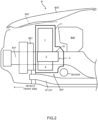
- FIG. 2 is a side view illustrating the example in which the in-vehicle fuel cell system according to the present embodiment is mounted on the vehicle front side.
- a first fuel cell stack 1 and a second fuel cell stack 2 which will be described later, are not illustrated.
- the in-vehicle fuel cell system (hereinafter, referred to as a "fuel cell system") according to the present embodiment is mounted on an electric vehicle that travels by a drive motor 73 (see FIG. 7 ).
- the electric vehicle includes a vehicle body B that is formed with a prime mover chamber (a front prime mover chamber B2F (see FIG. 3 ) or a rear prime mover chamber B2R (see FIG. 12 )), a cabin B4 (see FIG. 12 ), and the like, and a front suspension device SF (see FIG. 3 ) and a rear suspension device SR (see FIG. 12 ) that support the vehicle body B using a restoring force.
- a prime mover chamber a front prime mover chamber B2F (see FIG. 3 ) or a rear prime mover chamber B2R (see FIG. 12 )
- a cabin B4 see FIG. 12
- a front suspension device SF see FIG. 3
- a rear suspension device SR see FIG. 12
- an FF vehicle an FR vehicle
- an RR vehicle an RR vehicle to be described later is applied.
- the front prime mover chamber B2F is disposed on a front side of the vehicle body B.
- Side members B1F skeleton members
- a space occupying a position higher than the side member B1F is defined as a first internal space
- a space occupying a position lower than the side member B1F is defined as a second internal space.
- the front suspension device SF has a structure in which a wheel (not illustrated), a spring (not illustrated) that supports the vehicle body B via an arm (not illustrated) (or a link (not illustrated)) to which a knuckle (not illustrated) that holds the wheel and enables steering is attached, and a shock absorber (not illustrated) that absorbs vibration from a road surface are attached to a sub-frame S1F (a structural skeleton) on which a drive device B23 (the drive motor 73 (see FIG. 7 ), and a transaxle device (not illustrated)), and a steering device B24 are mounted.
- the rear suspension device SR see FIG.
- a wheel (not illustrated), a spring (not illustrated) that supports the vehicle body B via an arm (not illustrated) (or a link (not illustrated)) to which a hub (not illustrated) that holds the wheel is attached, and a shock absorber (not illustrated) that absorbs vibration from a road surface are attached to a sub-frame S1R (see FIG. 12 ).
- the front suspension device SF has a structure in which a wheel (not illustrated), a spring (not illustrated) that supports the vehicle body B via an arm (not illustrated) (or a link (not illustrated)) to which a knuckle (not illustrated) that holds the wheel and enables steering is attached, and a shock absorber (not illustrated) that absorbs vibration from a road surface are attached to the sub-frame S1F on which the drive device B23 (the drive motor 73 (see FIG. 7 )) and the steering device B24 (not illustrated) are mounted.
- the rear suspension device SR (see FIG.
- a wheel (not illustrated), a spring (not illustrated) that supports the vehicle body B via an arm (not illustrated) (or a link (not illustrated)) to which a hub (not illustrated) that holds the wheel is attached, and a shock absorber (not illustrated) that absorbs vibration from a road surface are attached to the sub-frame S1R on which a transaxle device (not illustrated) is mounted, and a driving force from the drive motor 73 (see FIG. 7 ) is transmitted to the transaxle device (not illustrated) via a propeller shaft (not illustrated).
- a configuration in which the drive motor 73 and the transaxle device (not illustrated) are integrated and attached to the rear suspension device SR, and thus the propeller shaft (not illustrated) is omitted can also be applied.
- a cooling device B21 such as a radiator is disposed on the vehicle front side of the front prime mover chamber B2F.
- An outfitting component B22 is disposed on a vehicle rear side in the first internal space of the front prime mover chamber B2F.
- an air box a built-in wiper system
- braking system components a master cylinder, a booster, a hydraulic pump, an ABS/VDC ACTR, and the like
- air conditioning system components a heater hose, and an A/C TUBE
- the drive device B23 the drive motor 73 (see FIG. 7 ), and the transaxle device), and the steering device B24 are disposed on the vehicle rear side in the second internal space of the front prime mover chamber B2F.
- An in-vehicle battery 72 (see FIG. 7 ) is disposed at a lower central portion of the vehicle.
- the drive motor 73 In the electric vehicle, during traveling, the drive motor 73 (see FIG. 7 ) is driven by supplying electric power from the in-vehicle battery 72 (see FIG. 7 ) to the drive motor 73 via an inverter (not illustrated), and during decelerating, regenerative electric power generated by the drive motor 73 is supplied to the in-vehicle battery 72 via the inverter (not illustrated) to charge the in-vehicle battery 72.
- the fuel cell system When an SOC (a charge amount) of the in-vehicle battery 72 reaches a predetermined lower limit value, the fuel cell system is started, and fuel cell stacks (the first fuel cell stack 1, and the second fuel cell stack 2) are caused to generate electric power to charge the in-vehicle battery 72.
- Electric power of auxiliary machines (a compressor 64 (see FIG. 7 ) and the like) constituting the fuel cell system is supplied from the in-vehicle battery 72 or an auxiliary machine battery (not illustrated).
- the auxiliary machine battery (not illustrated) is supplied with electric power from the fuel cell stacks.
- the fuel cell system according to the present embodiment is disposed at a position between the cooling device B21 and the outfitting component B22 (and the drive device B23, and the steering device B24) in the front prime mover chamber B2F.
- the fuel cell system includes a stacked structure A in which the first fuel cell stack 1 (a first fuel cell) and the second fuel cell stack 2 (a second fuel cell) are attached to an auxiliary machine structure 3 (a manifold) which is a housing including auxiliary machines (a heat exchanger 65, a combustor 67, and the like) of the fuel cell stack, and the second fuel cell stack 2, the auxiliary machine structure 3, and the first fuel cell stack 1 are stacked in order from the bottom.
- the stacked structure A is accommodated in a case 4, and the case 4 is attached to the side member B1F via brackets (a case-side bracket 41, and a vehicle-side bracket B6) ( FIG. 1 ). Details of the stacked structure A will be described later.
- the case 4 includes a tray-shaped front case 4F that accommodates the stacked structure A in the vehicle front side and to which the auxiliary machine structure 3 is attached, and a rear case 4R that accommodates the stacked structure A in the vehicle rear side and is connected to the front case 4F.
- the front case 4F and the rear case 4R are connected to each other with their opening portions aligned with each other, but a part of the opening portion of the rear case 4R remains open, and pipes connected to the auxiliary machine structure 3 extend from the open portion.
- the case-side bracket 41 extends from a position of the case 4 at substantially the same height as the auxiliary machine structure 3 (the side member B1F).
- the vehicle-side bracket B6 is attached to the side member B1F at a position facing the case-side bracket 41.
- the case-side bracket 41 is screwed to the vehicle-side bracket B6, the case 4 including the stacked structure A is fixed to the side member B1F.
- the case 4 suppresses a decrease in a temperature of the fuel cell stack by avoiding a traveling wind blowing to the stacked structure A, but may be omitted when an influence of the traveling wind is small.
- the auxiliary machine structure 3 is attached to the side member B1F via the vehicle-side bracket B6, or the auxiliary machine structure 3 is directly attached to the side member B1F. Since the case 4 also has a function of protecting the stacked structure A from curbstones or the like that enter the front prime mover chamber B2F (and the rear prime mover chamber B2R) from the road surface, it is also preferable to dispose the case 4 in a manner of covering at least a lower portion of the stacked structure A.
- the auxiliary machine structure 3 is disposed at substantially the same height as the side member B1F.
- the first fuel cell stack 1 is disposed in the first internal space
- the second fuel cell stack 2 is disposed in the second internal space.
- a distance in a height direction between the side member B1F and a hood B25 (a bonnet) that covers the front prime mover chamber B2F from above is longer than a distance in the height direction between the side member B1F and the sub-frame S1F (a height of the second internal space). Therefore, by setting the number of stacked fuel cells in the first fuel cell stack 1 to be larger than the number of stacked fuel cells in the second fuel cell stack 2, a dimension of the first fuel cell stack 1 in the height direction is set to be larger than a dimension of the second fuel cell stack 2 in the height direction.
- An upper end of the first fuel cell stack 1 (including an upper end of the case 4) is disposed lower than a virtual plane B3F which is set lower than the hood B25 (the bonnet) by a predetermined distance. Accordingly, a gap for impact reduction can be secured between the hood B25 and the stacked structure A (including the case 4), and thus for example, an impact on human at the time of occurrence of a traffic accident can be reduced, and particularly, a head of a pedestrian can be protected.
- a lower end of the second fuel cell stack 2 (including the case 4) is set higher than a lower end of the sub-frame S1F constituting the front suspension device SF. Accordingly, a direct hit caused by an on-road obstacle such as a curbstone or a rut can be avoided.
- the sub-frame S1F is one of strongest components among vehicle body system components. Therefore, when the sub-frame S1F is damaged, the traveling is influenced, and thus an abnormality of the front suspension device SF (or the rear suspension device SR) can be easily detected, and the damage of the case 4 can be easily estimated at that time.
- an end portion (a side surface) of the stacked structure A (the first fuel cell stack 1, the auxiliary machine structure 3, and the second fuel cell stack 2) on the front side of the electric vehicle is formed at substantially the same plane. Accordingly, the stacked structure A (including the case 4) can be disposed close to the cooling device B21, and a space behind the stacked structure A (including the case 4) can be expanded accordingly.
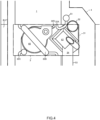
- FIG. 3 is a side view illustrating pipes attached to the in-vehicle fuel cell system according to the present embodiment.
- FIG. 4 is a partially enlarged view of FIG. 3 .
- a part of the auxiliary machine structure 3 is formed as a protruding portion 31 that protrudes rearward relative to the first fuel cell stack 1 and the second fuel cell stack 2.
- At least one of pipes for supplying fuel (an anode gas) and air (a cathode gas) to the first fuel cell stack 1 and the second fuel cell stack 2 is attached to the protruding portion 31 of the auxiliary machine structure 3.
- the fuel supply pipe 51 supplies fuel supplied from a fuel tank 61 (see FIG. 7 ) to the auxiliary machine structure 3.
- the air supply pipe 52 supplies air supplied from the compressor 64 (see FIG. 7 ) to the auxiliary machine structure 3.
- the off-gas exhaust pipe 53 discharges an off-gas (a combustion gas) discharged from the auxiliary machine structure 3 to the outside.
- the combustor 67 and the heat exchanger 65 can be disposed directly below the first fuel cell stack 1 and directly above the second fuel cell stack 2. Therefore, the off-gas (a fuel off-gas, and an air off-gas) discharged from the fuel cell stack can be supplied to the combustor 67 in a shortest distance, and air heated by the heat exchanger 65 can be supplied to the fuel cell stack in a shortest distance. Heat generated by the combustor 67 (the heat exchanger 65) is easily transferred to the fuel cell stack, and a thermal efficiency is improved.
- the heat exchanger 65 may be disposed adjacent to the combustor 67 as illustrated in FIGS. 3 and 4 , or may be disposed inside the combustor 67 as illustrated in FIG. 7 and the like.
- the fuel tank 61, the compressor 64, the auxiliary machine battery, and the like constituting the fuel cell system can be disposed at positions adjacent to the case 4 in the width direction of the electric vehicle (positions on a right side relative to the case 4 in FIG. 6 ) in the front prime mover chamber B2F.
- FIG. 5 is a view from the vehicle front side in a case where an in-vehicle fuel cell system according to a comparative example is mounted on the vehicle front side.
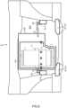
- FIG. 6 is a view from the vehicle front side in the example in which the in-vehicle fuel cell system according to the present embodiment is mounted on the vehicle front side.
- the fuel cell system according to the comparative example illustrated in FIG. 5 has the same configuration as that according to JP 2012-221630 A described above, and includes a stacked structure AA in which a second fuel cell stack 2A and a first fuel cell stack 1A are disposed in order on an auxiliary machine structure 3A including a combustor, a heat exchanger, a reformer, and the like.
- the stacked structure AA is fixed to the side member B1F by using, for example, a bracket B6A as in the invention.
- the auxiliary machine structure 3A that can be connected to the bracket B6A is a lowermost portion of the stacked structure AA, and thus the auxiliary machine structure 3A is disposed at a position lower than the side member B1F. Therefore, a size of the bracket B6A for attaching the auxiliary machine structure 3A to the side member B1F increases, and a weight increases accordingly.
- a length of a component extending in a vertical direction of the bracket B6A and a distance between the first fuel cell stack 1A and a portion fixed by the bracket B6A (the auxiliary machine structure 3A) in the stacked structure AA increase. Therefore, an amplitude of swing of the stacked structure AA and the bracket B6A increases during operation, and there is a concern that vibration damping performance and steering stability of the vehicle may be impaired.
- the auxiliary machine structure 3 constituting the stacked structure A according to the present embodiment illustrated in FIG. 6 is disposed at substantially the same height as the side member B1F. Therefore, a center of gravity of the stacked structure A is at substantially the same height as the side member B1F, and the brackets (the case-side bracket 41, and the vehicle-side bracket B6) can be connected to the stacked structure A at a position at a height position of the center of gravity of the stacked structure A (including the case 4).
- brackets (the case-side bracket 41, and the vehicle-side bracket B6) can be reduced, and the center of gravity of the stacked structure A is close to the brackets (the case-side bracket 41, and the vehicle-side bracket B6), and thus it is possible to suppress an amplitude of swing of the stacked structure A and the brackets (the case-side bracket 41, and the vehicle-side bracket B6) during operation, and to improve vibration damping performance and steering stability of the vehicle.
- the stacked structure AA according to the comparative example height dimensions (the number of stacked fuel cells) of the first fuel cell stack 1A and the second fuel cell stack 2A are the same. Therefore, in the stacked structure AA according to the comparative example, if a configuration in which the auxiliary machine structure 3A is sandwiched between the first fuel cell stack 1A and the second fuel cell stack 2A is constructed, and the stacked structure AA is mounted on the front prime mover chamber B2F in a manner that the auxiliary machine structure 3A is fixed to the side member B1F via the bracket, a problem in arrangement such as the second fuel cell stack 2A being lower than a lower end of the sub-frame S1F or the first fuel cell stack 1A coming into contact with the hood B25 occurs.
- the number of stacks in the first fuel cell stack 1 can be set according to an interval between the side member B1F and the virtual plane B3F
- the number of stacks in the second fuel cell stack 2 can be set according to an interval between the side member B1F and the lower end of the sub-frame S1F. Therefore, the stacked structure A (including the case 4) can be mounted on the front prime mover chamber B2F without exceeding the virtual plane B3F and without protruding from the lower end of the sub-frame S1F. Therefore, the stacked structure A (including the case 4) can be mounted on the front prime mover chamber B2F in an optimal state without changing a design of the electric vehicle, and an output of the fuel cell stack can be optimized.
- FIG. 7 is a diagram illustrating a basic configuration of the in-vehicle fuel cell system according to the present embodiment.
- the fuel cell system according to the present embodiment has a configuration in which the auxiliary machine structure 3 is disposed between the first fuel cell stack 1 and the second fuel cell stack 2.
- the combustor 67, the heat exchanger 65 disposed inside the combustor 67, and a valve 66 are accommodated in the auxiliary machine structure 3.
- the auxiliary machine structure 3 includes fuel flow paths 32A each connected to the fuel supply pipe 51 and connecting the fuel supply pipe 51 and an anode inlet of the first fuel cell stack 1, fuel flow paths 32B each connecting an anode outlet of the first fuel cell stack 1 and an anode inlet of the second fuel cell stack 2, a fuel flow path 32C connecting an anode outlet of the second fuel cell stack 2 and a fuel inlet of the combustor 67, and a fuel flow path 32D communicating with a second injector 63B and connected to the fuel inlet of the combustor 67.
- the auxiliary machine structure 3 includes an air flow path 33A connected to the air supply pipe 52 and connecting the air supply pipe 52 and an inlet of the heat exchanger 65, an air flow path 33B connecting an outlet of the heat exchanger 65 and a cathode inlet of the second fuel cell stack 2, an air flow path 33C connecting a cathode outlet of the second fuel cell stack 2 and a cathode inlet of the first fuel cell stack 1, an air flow path 33D connecting a cathode outlet of the first fuel cell stack 1 and an air inlet of the combustor 67, an air flow path 33E branching from a middle of the air flow path 33B and connected to an inlet of the valve 66, and an air flow path 33F connecting an outlet of the valve 66 and the fuel flow path 32A.
- the auxiliary machine structure 3 includes an off-gas flow path 34 connected to the off-gas exhaust pipe 53 and connecting an outlet of the combustor 67 and the off-gas exhaust pipe 53.
- the fuel cell system includes a fuel supply system that supplies fuel (the anode gas) to anodes of the first fuel cell stack 1 and the second fuel cell stack 2, respectively, an air supply system that supplies air (the cathode gas) to cathodes of the first fuel cell stack 1 and the second fuel cell stack 2, a gas combustion system that mixes and combusts the fuel off-gas discharged from the first fuel cell stack 1 and the air off-gas discharged from the second fuel cell stack 2, and an electric power supply system that causes the first fuel cell stack 1 and the second fuel cell stack 2 to generate electric power and supplies an extraction current to the in-vehicle battery 72.
- a fuel supply system that supplies fuel (the anode gas) to anodes of the first fuel cell stack 1 and the second fuel cell stack 2, respectively, an air supply system that supplies air (the cathode gas) to cathodes of the first fuel cell stack 1 and the second fuel cell stack 2, a gas combustion system that mixes and combusts the fuel off-gas discharged from the first fuel cell stack
- the fuel cell system includes a controller 8 that integrally controls the fuel supply system, the air supply system, the gas combustion system, and the electric power supply system.
- the auxiliary machine structure 3 is disposed between the first fuel cell stack 1 and the second fuel cell stack 2, and accommodates a part of the fuel supply system, the air supply system, and the gas combustion system.
- the fuel supply system includes the fuel tank 61 (TANK), a pump 62 (PUMP), and a first injector 63A (INJ 1).
- the pump 62 pressurizes fuel stored in the fuel tank 61 and supplies the pressurized fuel to the first injector 63A, and the first injector 63A supplies the fuel pressurized by the pump 62 to the anode of the first fuel cell stack 1.
- the anode of the first fuel cell stack 1 and the anode of the second fuel cell stack 2 are connected in series by the fuel flow path 32B, and are connected in a manner that the anode of the first fuel cell stack 1 is on an upstream side.
- the air supply system includes the compressor 64 (COMP), the heat exchanger 65 (HEX), and the valve 66.
- the compressor 64 introduces outside air and supplies the outside air to the heat exchanger 65, and the air heated by the heat exchanger 65 is supplied to the cathode of the second fuel cell stack 2.
- the cathode of the first fuel cell stack 1 and the cathode of the second fuel cell stack 2 are connected in series by the air flow path 33C, and are connected in a manner that the cathode of the second fuel cell stack 2 is on an upstream side.
- the valve 66 branches from the air flow path 33B and supplies air (oxygen) heated by the heat exchanger 65 to the anode of the first fuel cell stack 1 through the fuel flow path 32A at a predetermined flow rate.
- the gas combustion system includes the combustor 67 (CMB) and the second injector 63B (INJ2).
- the second injector 63B (INJ2) is connected in parallel with the first injector 63A (INJ 1) with respect to the pump 62, and supplies fuel to the combustor 67.
- the combustor 67 mixes fuel supplied from the second injector 63B (INJ2) and air (oxygen) supplied from the cathode of the second fuel cell stack 2 during the starting of the fuel cell system to generate a combustion gas, and heats the heat exchanger 65 (and the first fuel cell stack 1 and the second fuel cell stack 2) by the combustion gas.
- the combustor 67 mixes the fuel off-gas discharged from the anode of the second fuel cell stack 2 and the air off-gas discharged from the cathode of the first fuel cell stack 1 during generation of electric power by the first fuel cell stack 1 and the second fuel cell stack 2 to generate a combustion gas, and heats the heat exchanger 65 and the like.
- the combustion gas is finally discharged to the outside through the off-gas exhaust pipe 53.
- the electric power supply system includes a DC/DC converter 71 (CONV) that electrically connects the fuel cell stack to the in-vehicle battery 72 (BATT) (or the auxiliary machine battery) and the drive motor 73 (M).
- CONV DC/DC converter 71
- the fuel cell stack (the first fuel cell stack 1, and the second fuel cell stack 2) is a solid oxide fuel cell (SOFC).
- a catalyst for steam reforming (and partial oxidation reforming) the fuel is disposed in the first fuel cell stack 1. Further, air (oxygen) is supplied to the anode of the first fuel cell stack 1 via the valve 66 at a predetermined flow rate, and partial oxidation reforming can be performed on the fuel.
- the controller 8 starts the pump 62 and the second injector 63B to supply fuel to the combustor 67, and starts the compressor 64 to supply air (oxygen) to the combustor 67. Accordingly, the fuel and air (oxygen) are combusted in a mixed state in the combustor 67 to generate a combustion gas, thereby warming up the combustor 67 (the heat exchanger 65), the first fuel cell stack 1, and the second fuel cell stack 2.
- the controller 8 stops the second injector 63B, starts the first injector 63A, and starts the DC/DC converter 71. Accordingly, the first fuel cell stack 1 and the second fuel cell stack 2 start generating electric power.
- the fuel is subjected to steam reforming (an endothermic reaction) via the catalyst to be reformed into fuel containing hydrogen, and this fuel is used for electric power generation in the first fuel cell stack 1 and the second fuel cell stack 2.
- the controller 8 controls the valve 66 to supply air (oxygen) to the first fuel cell stack 1, and causes partial oxidation reforming (an exothermic reaction) of the fuel via the catalyst to suppress a decrease in the temperature of the first fuel cell stack 1.
- the controller 8 stops generation of electric power by the first fuel cell stack 1 and the second fuel cell stack 2 by stopping the DC/DC converter 71. Further, driving of the compressor 64 is continued to decrease the temperature of the fuel cell stack while the pump 62 and the first injector 63A are stopped. When the temperature of the fuel cell stack is decreased to a predetermined temperature, the controller 8 stops the compressor 64.
- FIG. 8 is a perspective view illustrating the fuel cell stack 2 and the auxiliary machine structure 3, which are components of the in-vehicle fuel cell system according to the present embodiment.
- FIG. 9 is an exploded perspective view illustrating the fuel cell stack 2 and the auxiliary machine structure 3, which are components of the in-vehicle fuel cell system according to the present embodiment.
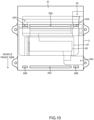
- FIG. 10 is a plan view illustrating the auxiliary machine structure 3 constituting the in-vehicle fuel cell system according to the present embodiment.
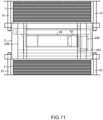
- FIG. 11 is a front view illustrating the in-vehicle fuel cell system according to the present embodiment.
- the fuel cell system according to the present embodiment is the stacked structure A in which the auxiliary machine structure 3 is disposed between the first fuel cell stack 1 and the second fuel cell stack 2, and the second fuel cell stack 2, the auxiliary machine structure 3, and the first fuel cell stack 1 are stacked in this order from the bottom.
- the first fuel cell stack 1 is formed by sandwiching the fuel cells stacked in multiple stages with an end plate 11 as the upper end and an upper surface of the auxiliary machine structure 3 as a lower end, and pressing the fuel cells from a stacking direction with fastening bolts 12.
- the second fuel cell stack 2 is formed by sandwiching the fuel cells stacked in multiple stages with an end plate 21 as the lower end and a lower surface of the auxiliary machine structure 3 as an upper end, and pressing the fuel cells from the stacking direction with fastening bolts 22.
- a current collector plate (not illustrated) is disposed on each of a lower surface of the end plate 11 and the upper surface of the auxiliary machine structure 3.
- the current collector plate (not illustrated) is electrically connected to the fuel cells constituting the first fuel cell stack 1, but is electrically insulated from the end plate 11 and the auxiliary machine structure 3. Therefore, an extraction current of the first fuel cell stack 1 can be extracted from the pair of current collector plates (not illustrated).
- a current collector plate (not illustrated) is disposed on each of an upper surface of the end plate 21 and the lower surface of the auxiliary machine structure 3, and an extraction current of the second fuel cell stack 2 can be extracted from the pair of current collector plates (not illustrated).
- FIGS. 9 , 10 , and the like illustrate the combustor 67 disposed in a central portion of the auxiliary machine structure 3 and the heat exchanger 65 disposed inside the combustor 67.
- FIGS. 9 , 10 , and the like illustrate the fuel flow paths 32A each introducing fuel from the outside and supplying the fuel to the anode of the first fuel cell stack 1, the fuel flow paths 32B each connecting the anode outlet of the first fuel cell stack 1 and the anode inlet of the second fuel cell stack 2, the air flow path 33A that supplies air to the heat exchanger 65, the air flow path 33C connecting the cathode outlet of the second fuel cell stack 2 and the cathode inlet of the first fuel cell stack 1, the air flow path 33D that supplies air (oxygen) exhausted from the cathode of the first fuel cell stack 1 to the combustor 67, and the off-gas flow path 34 for discharging the combustion gas discharged from the combustor 67 to the outside.
- the fuel flow paths 32B and the air flow path 33C are disposed at positions close to the front side of the vehicle relative to the combustor 67 (the heat exchanger 65) in the auxiliary machine structure 3.
- the fuel flow paths 32B connect the anode outlet of the first fuel cell stack 1 and the anode inlet of the second fuel cell stack 2, and are disposed in a pair, in which one fuel flow path 32B is disposed on one end side of the auxiliary machine structure 3 in the width direction of the electric vehicle, and the other fuel flow path 32B is disposed on the other end side of the auxiliary machine structure 3 in the width direction of the vehicle.
- the air flow path 33C connects the cathode outlet of the second fuel cell stack 2 and the cathode inlet of the first fuel cell stack 1.
- the air flow path 33C is disposed between the pair of fuel flow paths 32B, and is widely formed in the width direction of the electric vehicle. As illustrated in FIG. 10 , the air flow path 33C has substantially the same length as the heat exchanger 65 in the width direction of the electric vehicle, and is disposed in a manner of covering the heat exchanger 65 when viewed from the vehicle front side as illustrated in FIG. 11 .
- a side surface of the auxiliary machine structure 3 on the vehicle front side is a portion where a heat dissipation amount is largest due to the influence of the traveling wind.
- the air flow path 33C allows the cathode outlet of the second fuel cell stack 2 and the cathode inlet of the first fuel cell stack 1 to communicate with each other at a short distance, the heat dissipation amount therebetween can be suppressed.
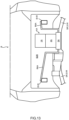
- FIG. 12 is a diagram illustrating a first modification in which the in-vehicle fuel cell system according to the present embodiment is mounted on a vehicle rear side.
- An electric vehicle to which the fuel cell system according to the first modification is applied is an RR vehicle, and the fuel cell system according to the first modification is attached to the rear prime mover chamber B2R of the electric vehicle.
- Side members B1R are disposed on the rear side of a vehicle body in a manner of extending in a front-rear direction of the vehicle and sandwiching the rear prime mover chamber B2R in a vehicle width direction.
- the rear prime mover chamber B2R and the cabin B4 are partitioned by a floor plate B5.
- a front suspension device (not illustrated) has a structure in which a spring that supports the vehicle body B and a shock absorber that absorbs vibration from a road surface are attached to a sub-frame on which a steering device is mounted.
- the rear suspension device SR has a structure in which a spring (not illustrated) that supports the vehicle body B and a shock absorber (not illustrated) that absorbs vibration from the road surface are attached to the sub-frame S1R on which the drive device B23 (the drive motor 73, and a transaxle device) is mounted.
- the stacked structure A in which the second fuel cell stack 2, the auxiliary machine structure 3, and the first fuel cell stack 1 are stacked in this order is accommodated in the case 4.
- the auxiliary machine structure 3 is disposed at substantially the same height position as the side member B1R, and the case 4 and the side member B1R are connected by brackets (the case-side bracket 41, the vehicle-side bracket B6) at substantially the same height position as the auxiliary machine structure 3 in the case 4, whereby the case 4 including the stacked structure A is fixed to the side member B1R.
- a distance in a height direction between the side member B1R and the floor plate B5 (a dimension of a first internal space in the height direction) is shorter than a distance in the height direction between the side member B1R and the sub-frame S1R (a dimension of a second internal space in the height direction). Therefore, by making the number of stacked fuel cells in the first fuel cell stack 1 smaller than the number of stacked fuel cells in the second fuel cell stack 2, the dimension of the first fuel cell stack 1 in the height direction is set smaller than the dimension of the second fuel cell stack 2 in the height direction.
- an upper end of the first fuel cell stack 1 (including an upper end of the case 4) is set lower than a virtual plane B3R positioned lower by a predetermined distance than the floor plate B5 positioned above the upper end. Accordingly, the fuel cell system can be mounted without changing a design of the cabin B4. Even if the floor plate B5 receives an impact from the cabin B4, damage to the fuel cell system can be avoided because the fuel cell system is separated from the floor plate B5 by a predetermined distance or more.
- a lower end of the second fuel cell stack 2 (including a lower end of the case 4) is set higher than a lower end of the sub-frame S1R constituting the rear suspension device SR. Accordingly, a direct hit caused by an on-road obstacle such as a curbstone or a rut can be avoided.
- An end portion (a side surface) of the stacked structure A (the first fuel cell stack 1, the auxiliary machine structure 3, and the second fuel cell stack 2) on the rear side of the electric vehicle is formed on substantially the same plane, and a part of the auxiliary machine structure 3 is formed as the protruding portion 31 that protrudes forward relative to the first fuel cell stack 1 and the second fuel cell stack 2 in an end portion of the stacked structure A on a vehicle front side.
- the case 4 including the stacked structure A illustrated in FIG. 2 and the like may be mounted on the rear prime mover chamber B2R while being reversed in the front-rear direction of the electric vehicle.
- the drive device B23 (the drive motor 73 (see FIG. 7 ), and the transaxle device) can be disposed in a region surrounded by the protruding portion 31, the second fuel cell stack 2 (including the case 4), and the sub-frame S1R, and the inside of the rear prime mover chamber B2R can be effectively used.
- At least one of pipes (the fuel supply pipe 51, and the air supply pipe 52) is connected to the protruding portion 31. Accordingly, in the first modification, the combustor 67 and the heat exchanger 65 can also be disposed directly below the first fuel cell stack 1 and directly above the second fuel cell stack 2.
- the fuel tank 61 (not illustrated) and the compressor 64 (not illustrated) are disposed in a front prime mover chamber (not illustrated), the fuel tank 61 communicates with the protruding portion 31 (the auxiliary machine structure 3) via the fuel supply pipe 51, and the compressor 64 communicates with the protruding portion 31 (the auxiliary machine structure 3) via the air supply pipe 52.
- the fuel tank 61 and the compressor 64 may be disposed in the rear prime mover chamber B2R.
- FIG. 13 is a view of the vehicle rear side in a case where the in-vehicle fuel cell system according to the comparative example is mounted on the vehicle rear side.
- FIG. 14 is a view from the vehicle rear side of the first modification in which the in-vehicle fuel cell system according to the present embodiment is mounted on the vehicle rear side.
- the fuel cell system according to the comparative example illustrated in FIG. 13 includes the stacked structure AA in which the second fuel cell stack 2A and the first fuel cell stack 1A are disposed in order on the auxiliary machine structure 3A including the combustor, the heat exchanger, the reformer, and the like.
- the stacked structure AA is fixed to the side member B1R by using, for example, the bracket B6A.
- the size of the bracket B6A for attaching the stacked structure AA to the side member B1R increases, and the weight increases accordingly. Accordingly, there is a concern that vibration damping performance and steering stability of the vehicle may be impaired.
- the auxiliary machine structure 3 constituting the stacked structure A in the first modification of the present embodiment illustrated in FIG. 14 is disposed at substantially the same height as the side member B1R. Therefore, for the same reason as described above, the sizes of the brackets (the case-side bracket 41, and the vehicle-side bracket B6) can be reduced, and since the center of gravity of the stacked structure A is close to the brackets, it is possible to suppress the amplitude of swing of the fuel cell system and the brackets during operation, and to improve vibration damping performance and steering stability of the vehicle.
- FIG. 15 is a diagram illustrating a second modification in which the in-vehicle fuel cell system according to the present embodiment is mounted on the vehicle rear side.
- the floor plate B5 behind the cabin B4 of the electric vehicle is set at, for example, substantially the same height as (or lower than) a lower end of a rear window B7.
- a distance in a height direction between the side member B1R and the floor plate B5 (a height of a first internal space) is larger than a distance in the height direction between the side member B1R and the sub-frame S1R (a height of a second internal space). Therefore, by making the number of stacked fuel cells in the first fuel cell stack 1 larger than the number of stacked fuel cells in the second fuel cell stack 2, a dimension of the first fuel cell stack 1 in the height direction is set larger than a dimension of the second fuel cell stack 2 in the height direction. In this way, the number of stacked fuel cells can be appropriately set according to the dimensions of the first internal space and the second internal space in the height direction. Therefore, the stacked structure A (including the case 4) can be mounted on the rear prime mover chamber B2R in an optimal state without changing a design of the electric vehicle, and an output of the fuel cell stack can be optimized.
- the in-vehicle fuel cell system includes: a fuel cell (the first fuel cell stack 1, the second fuel cell stack 2); an auxiliary machine (the combustor 67, the heat exchanger 65) configured to exchange a gas with the fuel cell (the first fuel cell stack 1, the second fuel cell stack 2); the in-vehicle fuel cell system includes: the auxiliary machine structure 3 configured to accommodate the auxiliary machine (the combustor 67, the heat exchanger 65), wherein the fuel cell (the first fuel cell stack 1, the second fuel cell stack 2) includes a first fuel cell (the first fuel cell stack 1) fixed to an upper surface of the auxiliary machine structure 3 and a second fuel cell (the second fuel cell stack 2) fixed to a lower surface of the auxiliary machine structure 3, the auxiliary machine structure 3 is disposed at substantially the same position in a height direction as a skeleton member (the side member B1F, the side member B1R) of the vehicle body B, and the first fuel cell (the first fuel cell stack 1) and the second fuel cell (the second fuel cell (the second
- the auxiliary machine structure 3 is disposed at substantially the same height as the skeleton member (the side member B1F, the side member B1R). Therefore, the center of gravity of the stacked structure A is at substantially the same height as the skeleton member (the side member B1F, the side member B1R), and the stacked structure A can be attached to the skeleton member (the side member B1F, the side member B1R) via the brackets (the case-side bracket 41, the vehicle-side bracket B6) at the height position of the center of gravity of the stacked structure A (including the case 4), or the stacked structure A can be directly attached to the skeleton member (the side member B1F, the side member B1R).
- the sizes of the brackets can be reduced, and the center of gravity of the stacked structure A is close to the brackets (the case-side bracket 41, the vehicle-side bracket B6), and thus it is possible to suppress an amplitude of swing of the stacked structure A and the brackets (the case-side bracket 41, the vehicle-side bracket B6) during operation, and to improve vibration damping performance and steering stability of the vehicle.
- the first fuel cell (the first fuel cell stack 1) is disposed in a first internal space occupying a position higher than the skeleton member (the side member B1F, the side member B1R) in the vehicle body B
- the second fuel cell (the second fuel cell stack 2) is disposed in a second internal space occupying a position lower than the skeleton member (the side member B1F, the side member B1R) in the vehicle body B.
- a height dimension of the first fuel cell is set to be larger than a height dimension of the second fuel cell
- the height dimension of the second fuel cell is set to be larger than the height of the first fuel cell
- the stacked structure A including the case 4) including the first fuel cell (the first fuel cell stack 1), the auxiliary machine structure 3, and the second fuel cell (the second fuel cell stack 2) can be mounted on the first internal space and the second internal space (the front prime mover chamber B2F or the rear prime mover chamber B2R) in an optimum state without changing a design of the electric vehicle, and the output of the fuel cell stack (the first fuel cell stack 1, the second fuel cell stack 2) can be optimized.
- a lower surface of the second fuel cell (the second fuel cell stack 2) is disposed above a lower surface of a structural skeleton (the sub-frame S1F) constituting the front suspension device SF.
- the fuel cell stack (in particular, the second fuel cell stack 2) can avoid a direct hit caused by an on-road obstacle such as a curbstone or a rut.
- an upper surface of the first fuel cell (the first fuel cell stack 1) is disposed at a position lower than the virtual plane B3F set at a position lower than the hood B25 by a predetermined distance, the hood B25 covering the front prime mover chamber B2F.
- a gap for impact reduction can be secured between the hood B25 and the stacked structure A (including the case 4), and thus for example, an impact on human at the time of occurrence of a traffic accident can be reduced, and particularly, a head of a pedestrian can be protected.
- an end portion of the stacked structure A on the vehicle front side is formed on substantially the same plane, and the protruding portion 31, which is a part of the auxiliary machine structure 3 and protrudes rearward relative to the first fuel cell (the first fuel cell stack 1) and the second fuel cell (the second fuel cell stack 2), is formed at an end portion of the stacked structure A on the vehicle rear side.
- the stacked structure A (including the case 4) can be disposed close to the cooling device B21, and a space behind the stacked structure A (including the case 4) can be expanded accordingly.
- the combustor 67 and the heat exchanger 65 can be disposed directly below the first fuel cell stack 1 and directly above the second fuel cell stack 2. Therefore, the off-gas (the fuel off-gas, the air off-gas) discharged from the fuel cell stack can be supplied to the combustor 67 in a shortest distance, and air heated by the heat exchanger 65 can be supplied to the fuel cell stack in a shortest distance. Heat generated by the combustor 67 (the heat exchanger 65) is easily transferred to the fuel cell stack, and a thermal efficiency is improved.
- the pipes (the fuel supply pipe 51, the air supply pipe 52, and the off-gas exhaust pipe 53) are disposed behind the stacked structure A, and thus a risk of damage to the pipes can be avoided when a frontal collision of the electric vehicle occurs.
- a lower surface of the second fuel cell (the second fuel cell stack 2) is disposed above a lower surface of a structural skeleton (the sub-frame S1R) constituting the rear suspension device SR.
- the fuel cell stack (in particular, the second fuel cell stack 2) can avoid a direct hit caused by an on-road obstacle such as a curbstone or a rut.
- an upper surface of the first fuel cell (the first fuel cell stack 1) is disposed at a position lower than the virtual plane B3R set at a position lower than the floor plate B5 at a rear portion of the cabin B4 by a predetermined distance.
- the in-vehicle fuel cell system can be mounted without or with a minimized change in the design of the cabin B4. Even if the floor plate B5 receives an impact from the cabin B4, damage to the in-vehicle fuel cell system can be avoided because the fuel cell system is separated from the floor plate B5 by a predetermined distance or more.
- an upper surface of the first fuel cell (the first fuel cell stack 1) is disposed at a position lower than the virtual plane B3R set at a position lower than the floor plate B5 of the cabin B4 by a predetermined distance.
- the in-vehicle fuel cell system can be mounted without or with a minimized change in the design of the cabin B4.
- the stacked structure A (including the case 4) can be mounted on the first internal space and the second internal space (the rear prime mover chamber B2R) in an optimum state, and the output of the fuel cell stack (the first fuel cell stack 1, the second fuel cell stack 2) can be optimized.
- an end portion of the stacked structure A on the vehicle rear side is formed on substantially the same plane, and the protruding portion 31, which is a part of the auxiliary machine structure 3 and protrudes forward relative to the first fuel cell (the first fuel cell stack 1) and the second fuel cell (the second fuel cell stack 2), is formed at an end portion of the stacked structure A on the vehicle front side.
- the drive device B23 (the drive motor 73 (see FIG. 7 ), and the transaxle device) can be disposed in a region surrounded by the protruding portion 31, the second fuel cell (the second fuel cell stack 2) (including the case 4), and the sub-frame S1R, and the inside of the rear prime mover chamber B2R can be effectively used.
- the end portion of the auxiliary machine structure 3 on the vehicle rear side on substantially the same plane, it is possible to avoid interference between the end portion of the auxiliary machine structure 3 on the vehicle rear side and a rearmost portion of the rear prime mover chamber B2R.
- At least one of the fuel supply pipe 51 configured to supply fuel to the first fuel cell (the first fuel cell stack 1) and the second fuel cell (the second fuel cell stack 2), and the air supply pipe 52 configured to supply air to the first fuel cell (the first fuel cell stack 1) and the second fuel cell (the second fuel cell stack 2) is connected to the protruding portion 31.
- auxiliary machines (the combustor 67 and the heat exchanger 65) can be disposed directly below the first fuel cell stack 1 and directly above the second fuel cell stack 2. Therefore, air heated by the heat exchanger 65 can be supplied to the fuel cell stack in a shortest distance. Heat generated by the combustor 67 (the heat exchanger 65) is easily transferred to the fuel cell stack, and a thermal efficiency is improved.
- the auxiliary machine structure 3 includes the air flow path 33C connecting a cathode of the first fuel cell (the first fuel cell stack 1) and a cathode of the second fuel cell (the second fuel cell stack 2).
- the auxiliary machine includes the combustor 67 configured to mix and combust a fuel off-gas discharged from the first fuel cell (the first fuel cell stack 1) and the second fuel cell (the second fuel cell stack 2) and an air off-gas discharged from the first fuel cell (the first fuel cell stack 1) and the second fuel cell (the second fuel cell stack 2), and the heat exchanger 65 configured to heat, by heat of the combustor 67, air to be supplied to the first fuel cell (the first fuel cell stack 1) and the second fuel cell (the second fuel cell stack 2).
- the air flow path 33C is disposed on the vehicle front side relative to the combustor 67 and the heat exchanger 65 in the auxiliary machine structure 3.
- the side surface of the auxiliary machine structure 3 on the vehicle front side is a portion where the heat dissipation amount is the largest due to the influence of the traveling wind. Accordingly, by disposing the air flow path 33C on the side surface of the auxiliary machine structure 3, which is on the vehicle front side, it is possible to suppress the decrease in the temperature of the heat exchanger 65 (and the combustor 67) due to the traveling wind. Since the air flow path 33C allows the cathode outlet of the second fuel cell stack 2 and the cathode inlet of the first fuel cell stack 1 to communicate with each other at a short distance, the heat dissipation amount therebetween can be suppressed.
- the auxiliary machine structure 3 includes a pair of fuel flow paths 32B connecting an anode of the first fuel cell (the first fuel cell stack 1) and an anode of the second fuel cell (the second fuel cell stack 2).
- the pair of fuel flow paths 32B are disposed on both end sides of the vehicle in a width direction in the auxiliary machine structure 3.
- the air flow path 33C is disposed between the pair of fuel flow paths 32B in the auxiliary machine structure 3, and is widely disposed in a manner that both ends of the air flow path 33C in the width direction are adjacent to the fuel flow paths 32B.
- the air flow path 33C is formed to be flat as a whole by reducing a dimension in the front-rear direction of the vehicle while maintaining a cross-sectional area (a pressure loss), and a space of the auxiliary machine structure 3 in the front-rear direction of the vehicle can be secured.
- the air flow path 33C is disposed in a manner of covering the heat exchanger 65 when viewed from the vehicle front side of the auxiliary machine structure 3.
- the decrease in the temperature of the heat exchanger 65 (and the combustor 67) due to the traveling wind can be efficiently suppressed.
Landscapes
- Engineering & Computer Science (AREA)
- Chemical & Material Sciences (AREA)
- Chemical Kinetics & Catalysis (AREA)
- Sustainable Development (AREA)
- Sustainable Energy (AREA)
- Manufacturing & Machinery (AREA)
- Life Sciences & Earth Sciences (AREA)
- Electrochemistry (AREA)
- General Chemical & Material Sciences (AREA)
- Combustion & Propulsion (AREA)
- Fuel Cell (AREA)
- Transportation (AREA)
- Mechanical Engineering (AREA)
- Electric Propulsion And Braking For Vehicles (AREA)
Abstract
Description
- The present invention relates to an in-vehicle fuel cell system.
-
JP 2012-221630 A - However, when the fuel cell system disclosed in
JP 2012-221630 A - Therefore, an object of the invention is to provide an in-vehicle fuel cell system that suppresses an increase in weight of a vehicle and suppresses a decrease in vibration damping performance and steering stability of the vehicle.
- An in-vehicle fuel cell system according to one embodiment of the present invention is an in-vehicle fuel cell system including a fuel cell, and an auxiliary machine configured to exchange a gas with the fuel cell, the in-vehicle fuel system including an auxiliary machine structure configured to accommodate the auxiliary machine, wherein the fuel cell includes a first fuel cell fixed to an upper surface of the auxiliary machine structure and a second fuel cell fixed to a lower surface of the auxiliary machine structure, the auxiliary machine structure is disposed at substantially the same position in a height direction as a skeleton member of a vehicle body, and the first fuel cell and the second fuel cell are fixed to the skeleton member via the auxiliary machine structure.
-
- [
FIG. 1] FIG. 1 is a perspective view illustrating an example in which an in-vehicle fuel cell system according to the present embodiment is mounted on a vehicle front side. - [
FIG. 2] FIG. 2 is a side view illustrating the example in which the in-vehicle fuel cell system according to the present embodiment is mounted on the vehicle front side. - [
FIG. 3] FIG. 3 is a side view illustrating pipes attached to the in-vehicle fuel cell system according to the present embodiment. - [
FIG. 4] FIG. 4 is a partially enlarged view ofFIG. 3 . - [
FIG. 5] FIG. 5 is a view from the vehicle front side in a case where an in-vehicle fuel cell system according to a comparative example is mounted on the vehicle front side. - [
FIG. 6] FIG. 6 is a view from the vehicle front side of the example in which the in-vehicle fuel cell system according to the present embodiment is mounted on the vehicle front side. - [
FIG. 7] FIG. 7 is a diagram illustrating a basic configuration of the in-vehicle fuel cell system according to the present embodiment. - [
FIG. 8] FIG. 8 is a perspective view illustrating fuel cell stacks and an auxiliary machine structure, which are components of the in-vehicle fuel cell system according to the present embodiment. - [
FIG. 9] FIG. 9 is an exploded perspective view illustrating the fuel cell stacks and the auxiliary machine structure, which are components of the in-vehicle fuel cell system according to the present embodiment. - [
FIG. 10] FIG. 10 is a plan view illustrating the auxiliary machine structure constituting the in-vehicle fuel cell system according to the present embodiment. - [
FIG. 11] FIG. 11 is a front view illustrating the in-vehicle fuel cell system according to the present embodiment. - [
FIG. 12] FIG. 12 is a diagram illustrating a first modification in which the in-vehicle fuel cell system according to the present embodiment is mounted on a vehicle rear side. - [
FIG. 13] FIG. 13 is a view from the vehicle rear side in a case where the in-vehicle fuel cell system according to the comparative example is mounted on the vehicle rear side. - [
FIG. 14] FIG. 14 is a view from the vehicle rear side of the first modification in which the in-vehicle fuel cell system according to the present embodiment is mounted on the vehicle rear side. - [
FIG. 15] FIG. 15 is a diagram illustrating a second modification in which the in-vehicle fuel cell system according to the present embodiment is mounted on the vehicle rear side. - Hereinafter, embodiments of the invention will be described with reference to the drawings.
-
FIG. 1 is a perspective view illustrating an example in which an in-vehicle fuel cell system according to the present embodiment is mounted on a vehicle front side.FIG. 2 is a side view illustrating the example in which the in-vehicle fuel cell system according to the present embodiment is mounted on the vehicle front side. InFIG. 1 , a firstfuel cell stack 1 and a secondfuel cell stack 2, which will be described later, are not illustrated. - The in-vehicle fuel cell system (hereinafter, referred to as a "fuel cell system") according to the present embodiment is mounted on an electric vehicle that travels by a drive motor 73 (see
FIG. 7 ). - The electric vehicle includes a vehicle body B that is formed with a prime mover chamber (a front prime mover chamber B2F (see
FIG. 3 ) or a rear prime mover chamber B2R (seeFIG. 12 )), a cabin B4 (seeFIG. 12 ), and the like, and a front suspension device SF (seeFIG. 3 ) and a rear suspension device SR (seeFIG. 12 ) that support the vehicle body B using a restoring force. - As the electric vehicle to which the present embodiment is applied, an FF vehicle (an FR vehicle) or an RR vehicle to be described later is applied.
- When the electric vehicle is the FF vehicle (the FR vehicle), the front prime mover chamber B2F is disposed on a front side of the vehicle body B. Side members B1F (skeleton members) are disposed on the front side of the vehicle body B in a manner of extending in a front-rear direction of the electric vehicle and sandwiching the front prime mover chamber B2F therebetween in a vehicle width direction. In the front prime mover chamber B2F (the same applies to the rear prime mover chamber B2R to be described later), a space occupying a position higher than the side member B1F is defined as a first internal space, and a space occupying a position lower than the side member B1F is defined as a second internal space.
- In a case of the FF vehicle, the front suspension device SF has a structure in which a wheel (not illustrated), a spring (not illustrated) that supports the vehicle body B via an arm (not illustrated) (or a link (not illustrated)) to which a knuckle (not illustrated) that holds the wheel and enables steering is attached, and a shock absorber (not illustrated) that absorbs vibration from a road surface are attached to a sub-frame S1F (a structural skeleton) on which a drive device B23 (the drive motor 73 (see
FIG. 7 ), and a transaxle device (not illustrated)), and a steering device B24 are mounted. Similarly, in a case of the RR vehicle, the rear suspension device SR (seeFIG. 12 ) has a structure in which a wheel (not illustrated), a spring (not illustrated) that supports the vehicle body B via an arm (not illustrated) (or a link (not illustrated)) to which a hub (not illustrated) that holds the wheel is attached, and a shock absorber (not illustrated) that absorbs vibration from a road surface are attached to a sub-frame S1R (seeFIG. 12 ). - In a case of the FR vehicle, the front suspension device SF has a structure in which a wheel (not illustrated), a spring (not illustrated) that supports the vehicle body B via an arm (not illustrated) (or a link (not illustrated)) to which a knuckle (not illustrated) that holds the wheel and enables steering is attached, and a shock absorber (not illustrated) that absorbs vibration from a road surface are attached to the sub-frame S1F on which the drive device B23 (the drive motor 73 (see
FIG. 7 )) and the steering device B24 (not illustrated) are mounted. The rear suspension device SR (seeFIG. 12 ) has a structure in which a wheel (not illustrated), a spring (not illustrated) that supports the vehicle body B via an arm (not illustrated) (or a link (not illustrated)) to which a hub (not illustrated) that holds the wheel is attached, and a shock absorber (not illustrated) that absorbs vibration from a road surface are attached to the sub-frame S1R on which a transaxle device (not illustrated) is mounted, and a driving force from the drive motor 73 (seeFIG. 7 ) is transmitted to the transaxle device (not illustrated) via a propeller shaft (not illustrated). A configuration in which thedrive motor 73 and the transaxle device (not illustrated) are integrated and attached to the rear suspension device SR, and thus the propeller shaft (not illustrated) is omitted can also be applied. - As illustrated in
FIG. 2 , a cooling device B21 such as a radiator is disposed on the vehicle front side of the front prime mover chamber B2F. - An outfitting component B22 is disposed on a vehicle rear side in the first internal space of the front prime mover chamber B2F. As the outfitting component B22, an air box (a built-in wiper system), braking system components (a master cylinder, a booster, a hydraulic pump, an ABS/VDC ACTR, and the like), and air conditioning system components (a heater hose, and an A/C TUBE) are disposed. The drive device B23 (the drive motor 73 (see
FIG. 7 ), and the transaxle device), and the steering device B24 are disposed on the vehicle rear side in the second internal space of the front prime mover chamber B2F. An in-vehicle battery 72 (seeFIG. 7 ) is disposed at a lower central portion of the vehicle. - In the electric vehicle, during traveling, the drive motor 73 (see
FIG. 7 ) is driven by supplying electric power from the in-vehicle battery 72 (seeFIG. 7 ) to thedrive motor 73 via an inverter (not illustrated), and during decelerating, regenerative electric power generated by thedrive motor 73 is supplied to the in-vehicle battery 72 via the inverter (not illustrated) to charge the in-vehicle battery 72. - When an SOC (a charge amount) of the in-
vehicle battery 72 reaches a predetermined lower limit value, the fuel cell system is started, and fuel cell stacks (the firstfuel cell stack 1, and the second fuel cell stack 2) are caused to generate electric power to charge the in-vehicle battery 72. - When the SOC of the in-
vehicle battery 72 reaches a predetermined upper limit value, the electric power generation is stopped. - Electric power of auxiliary machines (a compressor 64 (see
FIG. 7 ) and the like) constituting the fuel cell system is supplied from the in-vehicle battery 72 or an auxiliary machine battery (not illustrated). The auxiliary machine battery (not illustrated) is supplied with electric power from the fuel cell stacks. - The fuel cell system according to the present embodiment is disposed at a position between the cooling device B21 and the outfitting component B22 (and the drive device B23, and the steering device B24) in the front prime mover chamber B2F.
- As illustrated in
FIG. 2 , the fuel cell system according to the present embodiment includes a stacked structure A in which the first fuel cell stack 1 (a first fuel cell) and the second fuel cell stack 2 (a second fuel cell) are attached to an auxiliary machine structure 3 (a manifold) which is a housing including auxiliary machines (aheat exchanger 65, acombustor 67, and the like) of the fuel cell stack, and the secondfuel cell stack 2, theauxiliary machine structure 3, and the firstfuel cell stack 1 are stacked in order from the bottom. Further, the stacked structure A is accommodated in acase 4, and thecase 4 is attached to the side member B1F via brackets (a case-side bracket 41, and a vehicle-side bracket B6) (FIG. 1 ). Details of the stacked structure A will be described later. - As illustrated in
FIG. 1 , thecase 4 includes a tray-shaped front case 4F that accommodates the stacked structure A in the vehicle front side and to which theauxiliary machine structure 3 is attached, and a rear case 4R that accommodates the stacked structure A in the vehicle rear side and is connected to the front case 4F. The front case 4F and the rear case 4R are connected to each other with their opening portions aligned with each other, but a part of the opening portion of the rear case 4R remains open, and pipes connected to theauxiliary machine structure 3 extend from the open portion. - The case-
side bracket 41 extends from a position of thecase 4 at substantially the same height as the auxiliary machine structure 3 (the side member B1F). On the other hand, the vehicle-side bracket B6 is attached to the side member B1F at a position facing the case-side bracket 41. When the case-side bracket 41 is screwed to the vehicle-side bracket B6, thecase 4 including the stacked structure A is fixed to the side member B1F. - The
case 4 suppresses a decrease in a temperature of the fuel cell stack by avoiding a traveling wind blowing to the stacked structure A, but may be omitted when an influence of the traveling wind is small. In this case, for example, theauxiliary machine structure 3 is attached to the side member B1F via the vehicle-side bracket B6, or theauxiliary machine structure 3 is directly attached to the side member B1F. Since thecase 4 also has a function of protecting the stacked structure A from curbstones or the like that enter the front prime mover chamber B2F (and the rear prime mover chamber B2R) from the road surface, it is also preferable to dispose thecase 4 in a manner of covering at least a lower portion of the stacked structure A. - In the present embodiment, as illustrated in
FIG. 2 , theauxiliary machine structure 3 is disposed at substantially the same height as the side member B1F. The firstfuel cell stack 1 is disposed in the first internal space, and the secondfuel cell stack 2 is disposed in the second internal space. - In the front prime mover chamber B2F, a distance in a height direction between the side member B1F and a hood B25 (a bonnet) that covers the front prime mover chamber B2F from above (a height of the first internal space) is longer than a distance in the height direction between the side member B1F and the sub-frame S1F (a height of the second internal space). Therefore, by setting the number of stacked fuel cells in the first
fuel cell stack 1 to be larger than the number of stacked fuel cells in the secondfuel cell stack 2, a dimension of the firstfuel cell stack 1 in the height direction is set to be larger than a dimension of the secondfuel cell stack 2 in the height direction. - An upper end of the first fuel cell stack 1 (including an upper end of the case 4) is disposed lower than a virtual plane B3F which is set lower than the hood B25 (the bonnet) by a predetermined distance. Accordingly, a gap for impact reduction can be secured between the hood B25 and the stacked structure A (including the case 4), and thus for example, an impact on human at the time of occurrence of a traffic accident can be reduced, and particularly, a head of a pedestrian can be protected.
- A lower end of the second fuel cell stack 2 (including the case 4) is set higher than a lower end of the sub-frame S1F constituting the front suspension device SF. Accordingly, a direct hit caused by an on-road obstacle such as a curbstone or a rut can be avoided.
- Incidentally, even though a curbstone or the like collides with the
case 4, it is difficult to detect a crack of thecase 4 if damage due to the collision is small. However, even if the crack is small, there is a possibility that problems such as electric leakage or gas leakage of a high-temperature gas may occur during traveling in rainy weather or the like. - However, the sub-frame S1F is one of strongest components among vehicle body system components. Therefore, when the sub-frame S1F is damaged, the traveling is influenced, and thus an abnormality of the front suspension device SF (or the rear suspension device SR) can be easily detected, and the damage of the
case 4 can be easily estimated at that time. - As illustrated in
FIG. 2 , an end portion (a side surface) of the stacked structure A (the firstfuel cell stack 1, theauxiliary machine structure 3, and the second fuel cell stack 2) on the front side of the electric vehicle is formed at substantially the same plane. Accordingly, the stacked structure A (including the case 4) can be disposed close to the cooling device B21, and a space behind the stacked structure A (including the case 4) can be expanded accordingly. -
FIG. 3 is a side view illustrating pipes attached to the in-vehicle fuel cell system according to the present embodiment.FIG. 4 is a partially enlarged view ofFIG. 3 . - At an end portion of the stacked structure A on the vehicle rear side, a part of the
auxiliary machine structure 3 is formed as a protrudingportion 31 that protrudes rearward relative to the firstfuel cell stack 1 and the secondfuel cell stack 2. - As will be described in detail later, as illustrated in
FIG. 3 , at least one of pipes (afuel supply pipe 51, anair supply pipe 52, and an off-gas exhaust pipe 53) for supplying fuel (an anode gas) and air (a cathode gas) to the firstfuel cell stack 1 and the secondfuel cell stack 2 is attached to the protrudingportion 31 of theauxiliary machine structure 3. - Here, the
fuel supply pipe 51 supplies fuel supplied from a fuel tank 61 (seeFIG. 7 ) to theauxiliary machine structure 3. Theair supply pipe 52 supplies air supplied from the compressor 64 (seeFIG. 7 ) to theauxiliary machine structure 3. The off-gas exhaust pipe 53 discharges an off-gas (a combustion gas) discharged from theauxiliary machine structure 3 to the outside. - With such a configuration, the
combustor 67 and theheat exchanger 65 can be disposed directly below the firstfuel cell stack 1 and directly above the secondfuel cell stack 2. Therefore, the off-gas (a fuel off-gas, and an air off-gas) discharged from the fuel cell stack can be supplied to thecombustor 67 in a shortest distance, and air heated by theheat exchanger 65 can be supplied to the fuel cell stack in a shortest distance. Heat generated by the combustor 67 (the heat exchanger 65) is easily transferred to the fuel cell stack, and a thermal efficiency is improved. Further, by disposing the pipes (thefuel supply pipe 51, theair supply pipe 52, and the off-gas exhaust pipe 53) behind the stacked structure A, a risk of damage to the pipes can be avoided when a frontal collision of the electric vehicle occurs. Theheat exchanger 65 may be disposed adjacent to thecombustor 67 as illustrated inFIGS. 3 and4 , or may be disposed inside thecombustor 67 as illustrated inFIG. 7 and the like. - Although not illustrated, the
fuel tank 61, thecompressor 64, the auxiliary machine battery, and the like constituting the fuel cell system can be disposed at positions adjacent to thecase 4 in the width direction of the electric vehicle (positions on a right side relative to thecase 4 inFIG. 6 ) in the front prime mover chamber B2F. -
FIG. 5 is a view from the vehicle front side in a case where an in-vehicle fuel cell system according to a comparative example is mounted on the vehicle front side.FIG. 6 is a view from the vehicle front side in the example in which the in-vehicle fuel cell system according to the present embodiment is mounted on the vehicle front side. - The fuel cell system according to the comparative example illustrated in
FIG. 5 has the same configuration as that according toJP 2012-221630 A fuel cell stack 2A and a firstfuel cell stack 1A are disposed in order on anauxiliary machine structure 3A including a combustor, a heat exchanger, a reformer, and the like. - When such a stacked structure AA is disposed in the front prime mover chamber B2F, the stacked structure AA is fixed to the side member B1F by using, for example, a bracket B6A as in the invention. However, in the stacked structure AA according to the comparative example, the
auxiliary machine structure 3A that can be connected to the bracket B6A is a lowermost portion of the stacked structure AA, and thus theauxiliary machine structure 3A is disposed at a position lower than the side member B1F. Therefore, a size of the bracket B6A for attaching theauxiliary machine structure 3A to the side member B1F increases, and a weight increases accordingly. A length of a component extending in a vertical direction of the bracket B6A and a distance between the firstfuel cell stack 1A and a portion fixed by the bracket B6A (theauxiliary machine structure 3A) in the stacked structure AA increase. Therefore, an amplitude of swing of the stacked structure AA and the bracket B6A increases during operation, and there is a concern that vibration damping performance and steering stability of the vehicle may be impaired. - On the other hand, the
auxiliary machine structure 3 constituting the stacked structure A according to the present embodiment illustrated inFIG. 6 is disposed at substantially the same height as the side member B1F. Therefore, a center of gravity of the stacked structure A is at substantially the same height as the side member B1F, and the brackets (the case-side bracket 41, and the vehicle-side bracket B6) can be connected to the stacked structure A at a position at a height position of the center of gravity of the stacked structure A (including the case 4). Accordingly, sizes of the brackets (the case-side bracket 41, and the vehicle-side bracket B6) can be reduced, and the center of gravity of the stacked structure A is close to the brackets (the case-side bracket 41, and the vehicle-side bracket B6), and thus it is possible to suppress an amplitude of swing of the stacked structure A and the brackets (the case-side bracket 41, and the vehicle-side bracket B6) during operation, and to improve vibration damping performance and steering stability of the vehicle. - In the stacked structure AA according to the comparative example, height dimensions (the number of stacked fuel cells) of the first
fuel cell stack 1A and the secondfuel cell stack 2A are the same. Therefore, in the stacked structure AA according to the comparative example, if a configuration in which theauxiliary machine structure 3A is sandwiched between the firstfuel cell stack 1A and the secondfuel cell stack 2A is constructed, and the stacked structure AA is mounted on the front prime mover chamber B2F in a manner that theauxiliary machine structure 3A is fixed to the side member B1F via the bracket, a problem in arrangement such as the secondfuel cell stack 2A being lower than a lower end of the sub-frame S1F or the firstfuel cell stack 1A coming into contact with the hood B25 occurs. - In contrast, in the stacked structure A according to the present embodiment, the number of stacks in the first
fuel cell stack 1 can be set according to an interval between the side member B1F and the virtual plane B3F, and the number of stacks in the secondfuel cell stack 2 can be set according to an interval between the side member B1F and the lower end of the sub-frame S1F. Therefore, the stacked structure A (including the case 4) can be mounted on the front prime mover chamber B2F without exceeding the virtual plane B3F and without protruding from the lower end of the sub-frame S1F. Therefore, the stacked structure A (including the case 4) can be mounted on the front prime mover chamber B2F in an optimal state without changing a design of the electric vehicle, and an output of the fuel cell stack can be optimized. -
FIG. 7 is a diagram illustrating a basic configuration of the in-vehicle fuel cell system according to the present embodiment. As described above, the fuel cell system according to the present embodiment has a configuration in which theauxiliary machine structure 3 is disposed between the firstfuel cell stack 1 and the secondfuel cell stack 2. - For example, the
combustor 67, theheat exchanger 65 disposed inside thecombustor 67, and avalve 66 are accommodated in theauxiliary machine structure 3. - The
auxiliary machine structure 3 includesfuel flow paths 32A each connected to thefuel supply pipe 51 and connecting thefuel supply pipe 51 and an anode inlet of the firstfuel cell stack 1,fuel flow paths 32B each connecting an anode outlet of the firstfuel cell stack 1 and an anode inlet of the secondfuel cell stack 2, afuel flow path 32C connecting an anode outlet of the secondfuel cell stack 2 and a fuel inlet of thecombustor 67, and afuel flow path 32D communicating with asecond injector 63B and connected to the fuel inlet of thecombustor 67. - The
auxiliary machine structure 3 includes anair flow path 33A connected to theair supply pipe 52 and connecting theair supply pipe 52 and an inlet of theheat exchanger 65, anair flow path 33B connecting an outlet of theheat exchanger 65 and a cathode inlet of the secondfuel cell stack 2, anair flow path 33C connecting a cathode outlet of the secondfuel cell stack 2 and a cathode inlet of the firstfuel cell stack 1, anair flow path 33D connecting a cathode outlet of the firstfuel cell stack 1 and an air inlet of thecombustor 67, anair flow path 33E branching from a middle of theair flow path 33B and connected to an inlet of thevalve 66, and anair flow path 33F connecting an outlet of thevalve 66 and thefuel flow path 32A. - The
auxiliary machine structure 3 includes an off-gas flow path 34 connected to the off-gas exhaust pipe 53 and connecting an outlet of thecombustor 67 and the off-gas exhaust pipe 53. - The fuel cell system according to the present embodiment includes a fuel supply system that supplies fuel (the anode gas) to anodes of the first
fuel cell stack 1 and the secondfuel cell stack 2, respectively, an air supply system that supplies air (the cathode gas) to cathodes of the firstfuel cell stack 1 and the secondfuel cell stack 2, a gas combustion system that mixes and combusts the fuel off-gas discharged from the firstfuel cell stack 1 and the air off-gas discharged from the secondfuel cell stack 2, and an electric power supply system that causes the firstfuel cell stack 1 and the secondfuel cell stack 2 to generate electric power and supplies an extraction current to the in-vehicle battery 72. - The fuel cell system according to the present embodiment includes a controller 8 that integrally controls the fuel supply system, the air supply system, the gas combustion system, and the electric power supply system.
- In the fuel cell system according to the present embodiment, the
auxiliary machine structure 3 is disposed between the firstfuel cell stack 1 and the secondfuel cell stack 2, and accommodates a part of the fuel supply system, the air supply system, and the gas combustion system. - The fuel supply system includes the fuel tank 61 (TANK), a pump 62 (PUMP), and a
first injector 63A (INJ 1). Thepump 62 pressurizes fuel stored in thefuel tank 61 and supplies the pressurized fuel to thefirst injector 63A, and thefirst injector 63A supplies the fuel pressurized by thepump 62 to the anode of the firstfuel cell stack 1. In the fuel supply system, the anode of the firstfuel cell stack 1 and the anode of the secondfuel cell stack 2 are connected in series by thefuel flow path 32B, and are connected in a manner that the anode of the firstfuel cell stack 1 is on an upstream side. - The air supply system includes the compressor 64 (COMP), the heat exchanger 65 (HEX), and the
valve 66. Thecompressor 64 introduces outside air and supplies the outside air to theheat exchanger 65, and the air heated by theheat exchanger 65 is supplied to the cathode of the secondfuel cell stack 2. In the air supply system, the cathode of the firstfuel cell stack 1 and the cathode of the secondfuel cell stack 2 are connected in series by theair flow path 33C, and are connected in a manner that the cathode of the secondfuel cell stack 2 is on an upstream side. Thevalve 66 branches from theair flow path 33B and supplies air (oxygen) heated by theheat exchanger 65 to the anode of the firstfuel cell stack 1 through thefuel flow path 32A at a predetermined flow rate. - The gas combustion system includes the combustor 67 (CMB) and the
second injector 63B (INJ2). Thesecond injector 63B (INJ2) is connected in parallel with thefirst injector 63A (INJ 1) with respect to thepump 62, and supplies fuel to thecombustor 67. Thecombustor 67 mixes fuel supplied from thesecond injector 63B (INJ2) and air (oxygen) supplied from the cathode of the secondfuel cell stack 2 during the starting of the fuel cell system to generate a combustion gas, and heats the heat exchanger 65 (and the firstfuel cell stack 1 and the second fuel cell stack 2) by the combustion gas. Thecombustor 67 mixes the fuel off-gas discharged from the anode of the secondfuel cell stack 2 and the air off-gas discharged from the cathode of the firstfuel cell stack 1 during generation of electric power by the firstfuel cell stack 1 and the secondfuel cell stack 2 to generate a combustion gas, and heats theheat exchanger 65 and the like. The combustion gas is finally discharged to the outside through the off-gas exhaust pipe 53. - The electric power supply system includes a DC/DC converter 71 (CONV) that electrically connects the fuel cell stack to the in-vehicle battery 72 (BATT) (or the auxiliary machine battery) and the drive motor 73 (M).
- The fuel cell stack (the first
fuel cell stack 1, and the second fuel cell stack 2) is a solid oxide fuel cell (SOFC). A catalyst for steam reforming (and partial oxidation reforming) the fuel is disposed in the firstfuel cell stack 1. Further, air (oxygen) is supplied to the anode of the firstfuel cell stack 1 via thevalve 66 at a predetermined flow rate, and partial oxidation reforming can be performed on the fuel. - When the SOC of the in-
vehicle battery 72 reaches the predetermined lower limit value, the controller 8 starts thepump 62 and thesecond injector 63B to supply fuel to thecombustor 67, and starts thecompressor 64 to supply air (oxygen) to thecombustor 67. Accordingly, the fuel and air (oxygen) are combusted in a mixed state in thecombustor 67 to generate a combustion gas, thereby warming up the combustor 67 (the heat exchanger 65), the firstfuel cell stack 1, and the secondfuel cell stack 2. - When a temperature of the
combustor 67 reaches a predetermined temperature and temperatures of the firstfuel cell stack 1 and the secondfuel cell stack 2 reach a temperature at which the firstfuel cell stack 1 and the secondfuel cell stack 2 can generate electric power, the controller 8 stops thesecond injector 63B, starts thefirst injector 63A, and starts the DC/DC converter 71. Accordingly, the firstfuel cell stack 1 and the secondfuel cell stack 2 start generating electric power. - At this time, in the first
fuel cell stack 1, the fuel is subjected to steam reforming (an endothermic reaction) via the catalyst to be reformed into fuel containing hydrogen, and this fuel is used for electric power generation in the firstfuel cell stack 1 and the secondfuel cell stack 2. The controller 8 controls thevalve 66 to supply air (oxygen) to the firstfuel cell stack 1, and causes partial oxidation reforming (an exothermic reaction) of the fuel via the catalyst to suppress a decrease in the temperature of the firstfuel cell stack 1. - When the SOC of the in-
vehicle battery 72 reaches the predetermined upper limit value, the controller 8 stops generation of electric power by the firstfuel cell stack 1 and the secondfuel cell stack 2 by stopping the DC/DC converter 71. Further, driving of thecompressor 64 is continued to decrease the temperature of the fuel cell stack while thepump 62 and thefirst injector 63A are stopped. When the temperature of the fuel cell stack is decreased to a predetermined temperature, the controller 8 stops thecompressor 64. -
FIG. 8 is a perspective view illustrating thefuel cell stack 2 and theauxiliary machine structure 3, which are components of the in-vehicle fuel cell system according to the present embodiment.FIG. 9 is an exploded perspective view illustrating thefuel cell stack 2 and theauxiliary machine structure 3, which are components of the in-vehicle fuel cell system according to the present embodiment.FIG. 10 is a plan view illustrating theauxiliary machine structure 3 constituting the in-vehicle fuel cell system according to the present embodiment.FIG. 11 is a front view illustrating the in-vehicle fuel cell system according to the present embodiment. - As described above, the fuel cell system according to the present embodiment is the stacked structure A in which the
auxiliary machine structure 3 is disposed between the firstfuel cell stack 1 and the secondfuel cell stack 2, and the secondfuel cell stack 2, theauxiliary machine structure 3, and the firstfuel cell stack 1 are stacked in this order from the bottom. - The first
fuel cell stack 1 is formed by sandwiching the fuel cells stacked in multiple stages with anend plate 11 as the upper end and an upper surface of theauxiliary machine structure 3 as a lower end, and pressing the fuel cells from a stacking direction withfastening bolts 12. - The second
fuel cell stack 2 is formed by sandwiching the fuel cells stacked in multiple stages with anend plate 21 as the lower end and a lower surface of theauxiliary machine structure 3 as an upper end, and pressing the fuel cells from the stacking direction withfastening bolts 22. - A current collector plate (not illustrated) is disposed on each of a lower surface of the
end plate 11 and the upper surface of theauxiliary machine structure 3. The current collector plate (not illustrated) is electrically connected to the fuel cells constituting the firstfuel cell stack 1, but is electrically insulated from theend plate 11 and theauxiliary machine structure 3. Therefore, an extraction current of the firstfuel cell stack 1 can be extracted from the pair of current collector plates (not illustrated). Similarly, a current collector plate (not illustrated) is disposed on each of an upper surface of theend plate 21 and the lower surface of theauxiliary machine structure 3, and an extraction current of the secondfuel cell stack 2 can be extracted from the pair of current collector plates (not illustrated). -
FIGS. 9 ,10 , and the like illustrate thecombustor 67 disposed in a central portion of theauxiliary machine structure 3 and theheat exchanger 65 disposed inside thecombustor 67.FIGS. 9 ,10 , and the like illustrate thefuel flow paths 32A each introducing fuel from the outside and supplying the fuel to the anode of the firstfuel cell stack 1, thefuel flow paths 32B each connecting the anode outlet of the firstfuel cell stack 1 and the anode inlet of the secondfuel cell stack 2, theair flow path 33A that supplies air to theheat exchanger 65, theair flow path 33C connecting the cathode outlet of the secondfuel cell stack 2 and the cathode inlet of the firstfuel cell stack 1, theair flow path 33D that supplies air (oxygen) exhausted from the cathode of the firstfuel cell stack 1 to thecombustor 67, and the off-gas flow path 34 for discharging the combustion gas discharged from thecombustor 67 to the outside. - As illustrated in
FIGS. 9 to 11 , thefuel flow paths 32B and theair flow path 33C are disposed at positions close to the front side of the vehicle relative to the combustor 67 (the heat exchanger 65) in theauxiliary machine structure 3. Thefuel flow paths 32B connect the anode outlet of the firstfuel cell stack 1 and the anode inlet of the secondfuel cell stack 2, and are disposed in a pair, in which onefuel flow path 32B is disposed on one end side of theauxiliary machine structure 3 in the width direction of the electric vehicle, and the otherfuel flow path 32B is disposed on the other end side of theauxiliary machine structure 3 in the width direction of the vehicle. - The
air flow path 33C connects the cathode outlet of the secondfuel cell stack 2 and the cathode inlet of the firstfuel cell stack 1. Theair flow path 33C is disposed between the pair offuel flow paths 32B, and is widely formed in the width direction of the electric vehicle. As illustrated inFIG. 10 , theair flow path 33C has substantially the same length as theheat exchanger 65 in the width direction of the electric vehicle, and is disposed in a manner of covering theheat exchanger 65 when viewed from the vehicle front side as illustrated inFIG. 11 . A side surface of theauxiliary machine structure 3 on the vehicle front side is a portion where a heat dissipation amount is largest due to the influence of the traveling wind. Therefore, by disposing theair flow path 33C on the side surface, even in a configuration in which theheat exchanger 65 is disposed in front of thecombustor 67 as illustrated inFIG. 3 , the decrease in the temperature due to the traveling wind can be suppressed. In particular, by widely forming theair flow path 33C in the width direction of the electric vehicle, the decrease in the temperature of the heat exchanger 65 (and the combustor 67) due to the traveling wind can be efficiently suppressed. Since theair flow path 33C allows the cathode outlet of the secondfuel cell stack 2 and the cathode inlet of the firstfuel cell stack 1 to communicate with each other at a short distance, the heat dissipation amount therebetween can be suppressed. -
FIG. 12 is a diagram illustrating a first modification in which the in-vehicle fuel cell system according to the present embodiment is mounted on a vehicle rear side. An electric vehicle to which the fuel cell system according to the first modification is applied is an RR vehicle, and the fuel cell system according to the first modification is attached to the rear prime mover chamber B2R of the electric vehicle. - Side members B1R (see
FIG. 14 ) are disposed on the rear side of a vehicle body in a manner of extending in a front-rear direction of the vehicle and sandwiching the rear prime mover chamber B2R in a vehicle width direction. The rear prime mover chamber B2R and the cabin B4 are partitioned by a floor plate B5. - When the electric vehicle is the RR vehicle, a front suspension device (not illustrated) has a structure in which a spring that supports the vehicle body B and a shock absorber that absorbs vibration from a road surface are attached to a sub-frame on which a steering device is mounted. The rear suspension device SR has a structure in which a spring (not illustrated) that supports the vehicle body B and a shock absorber (not illustrated) that absorbs vibration from the road surface are attached to the sub-frame S1R on which the drive device B23 (the
drive motor 73, and a transaxle device) is mounted. - Similarly to the fuel cell system illustrated in
FIG. 1 and the like, in the fuel cell system in the first modification, the stacked structure A in which the secondfuel cell stack 2, theauxiliary machine structure 3, and the firstfuel cell stack 1 are stacked in this order is accommodated in thecase 4. Theauxiliary machine structure 3 is disposed at substantially the same height position as the side member B1R, and thecase 4 and the side member B1R are connected by brackets (the case-side bracket 41, the vehicle-side bracket B6) at substantially the same height position as theauxiliary machine structure 3 in thecase 4, whereby thecase 4 including the stacked structure A is fixed to the side member B1R. - As illustrated in
FIG. 12 , for example, in the rear prime mover chamber B2R, a distance in a height direction between the side member B1R and the floor plate B5 (a dimension of a first internal space in the height direction) is shorter than a distance in the height direction between the side member B1R and the sub-frame S1R (a dimension of a second internal space in the height direction). Therefore, by making the number of stacked fuel cells in the firstfuel cell stack 1 smaller than the number of stacked fuel cells in the secondfuel cell stack 2, the dimension of the firstfuel cell stack 1 in the height direction is set smaller than the dimension of the secondfuel cell stack 2 in the height direction. - As illustrated in
FIG. 12 , an upper end of the first fuel cell stack 1 (including an upper end of the case 4) is set lower than a virtual plane B3R positioned lower by a predetermined distance than the floor plate B5 positioned above the upper end. Accordingly, the fuel cell system can be mounted without changing a design of the cabin B4. Even if the floor plate B5 receives an impact from the cabin B4, damage to the fuel cell system can be avoided because the fuel cell system is separated from the floor plate B5 by a predetermined distance or more. - A lower end of the second fuel cell stack 2 (including a lower end of the case 4) is set higher than a lower end of the sub-frame S1R constituting the rear suspension device SR. Accordingly, a direct hit caused by an on-road obstacle such as a curbstone or a rut can be avoided.
- An end portion (a side surface) of the stacked structure A (the first
fuel cell stack 1, theauxiliary machine structure 3, and the second fuel cell stack 2) on the rear side of the electric vehicle is formed on substantially the same plane, and a part of theauxiliary machine structure 3 is formed as the protrudingportion 31 that protrudes forward relative to the firstfuel cell stack 1 and the secondfuel cell stack 2 in an end portion of the stacked structure A on a vehicle front side. In this case, for example, thecase 4 including the stacked structure A illustrated inFIG. 2 and the like may be mounted on the rear prime mover chamber B2R while being reversed in the front-rear direction of the electric vehicle. - Accordingly, in the rear prime mover chamber B2R, the drive device B23 (the drive motor 73 (see
FIG. 7 ), and the transaxle device) can be disposed in a region surrounded by the protrudingportion 31, the second fuel cell stack 2 (including the case 4), and the sub-frame S1R, and the inside of the rear prime mover chamber B2R can be effectively used. - At least one of pipes (the
fuel supply pipe 51, and the air supply pipe 52) is connected to the protrudingportion 31. Accordingly, in the first modification, thecombustor 67 and theheat exchanger 65 can also be disposed directly below the firstfuel cell stack 1 and directly above the secondfuel cell stack 2. - In the above configuration, the fuel tank 61 (not illustrated) and the compressor 64 (not illustrated) are disposed in a front prime mover chamber (not illustrated), the
fuel tank 61 communicates with the protruding portion 31 (the auxiliary machine structure 3) via thefuel supply pipe 51, and thecompressor 64 communicates with the protruding portion 31 (the auxiliary machine structure 3) via theair supply pipe 52. Of course, thefuel tank 61 and thecompressor 64 may be disposed in the rear prime mover chamber B2R. -
FIG. 13 is a view of the vehicle rear side in a case where the in-vehicle fuel cell system according to the comparative example is mounted on the vehicle rear side.FIG. 14 is a view from the vehicle rear side of the first modification in which the in-vehicle fuel cell system according to the present embodiment is mounted on the vehicle rear side. - Similarly to the fuel cell system illustrated in
FIG. 5 , the fuel cell system according to the comparative example illustrated inFIG. 13 includes the stacked structure AA in which the secondfuel cell stack 2A and the firstfuel cell stack 1A are disposed in order on theauxiliary machine structure 3A including the combustor, the heat exchanger, the reformer, and the like. - When such a stacked structure AA is disposed in the rear prime mover chamber B2R, the stacked structure AA is fixed to the side member B1R by using, for example, the bracket B6A. However, for the same reason as described above, the size of the bracket B6A for attaching the stacked structure AA to the side member B1R increases, and the weight increases accordingly. Accordingly, there is a concern that vibration damping performance and steering stability of the vehicle may be impaired.
- On the other hand, the
auxiliary machine structure 3 constituting the stacked structure A in the first modification of the present embodiment illustrated inFIG. 14 is disposed at substantially the same height as the side member B1R. Therefore, for the same reason as described above, the sizes of the brackets (the case-side bracket 41, and the vehicle-side bracket B6) can be reduced, and since the center of gravity of the stacked structure A is close to the brackets, it is possible to suppress the amplitude of swing of the fuel cell system and the brackets during operation, and to improve vibration damping performance and steering stability of the vehicle. -
FIG. 15 is a diagram illustrating a second modification in which the in-vehicle fuel cell system according to the present embodiment is mounted on the vehicle rear side. In an electric vehicle to which the second modification is applied, the floor plate B5 behind the cabin B4 of the electric vehicle is set at, for example, substantially the same height as (or lower than) a lower end of a rear window B7. - As illustrated in
FIG. 15 , in the rear prime mover chamber B2R, a distance in a height direction between the side member B1R and the floor plate B5 (a height of a first internal space) is larger than a distance in the height direction between the side member B1R and the sub-frame S1R (a height of a second internal space). Therefore, by making the number of stacked fuel cells in the firstfuel cell stack 1 larger than the number of stacked fuel cells in the secondfuel cell stack 2, a dimension of the firstfuel cell stack 1 in the height direction is set larger than a dimension of the secondfuel cell stack 2 in the height direction. In this way, the number of stacked fuel cells can be appropriately set according to the dimensions of the first internal space and the second internal space in the height direction. Therefore, the stacked structure A (including the case 4) can be mounted on the rear prime mover chamber B2R in an optimal state without changing a design of the electric vehicle, and an output of the fuel cell stack can be optimized. - The in-vehicle fuel cell system according to the present embodiment includes: a fuel cell (the first fuel cell stack 1, the second fuel cell stack 2); an auxiliary machine (the combustor 67, the heat exchanger 65) configured to exchange a gas with the fuel cell (the first fuel cell stack 1, the second fuel cell stack 2); the in-vehicle fuel cell system includes: the auxiliary machine structure 3 configured to accommodate the auxiliary machine (the combustor 67, the heat exchanger 65), wherein the fuel cell (the first fuel cell stack 1, the second fuel cell stack 2) includes a first fuel cell (the first fuel cell stack 1) fixed to an upper surface of the auxiliary machine structure 3 and a second fuel cell (the second fuel cell stack 2) fixed to a lower surface of the auxiliary machine structure 3, the auxiliary machine structure 3 is disposed at substantially the same position in a height direction as a skeleton member (the side member B1F, the side member B1R) of the vehicle body B, and the first fuel cell (the first fuel cell stack 1) and the second fuel cell (the second fuel cell stack 2) are fixed to the skeleton member (the side member B1F, the side member B1R) via the auxiliary machine structure 3.
- According to the above configuration, the
auxiliary machine structure 3 is disposed at substantially the same height as the skeleton member (the side member B1F, the side member B1R). Therefore, the center of gravity of the stacked structure A is at substantially the same height as the skeleton member (the side member B1F, the side member B1R), and the stacked structure A can be attached to the skeleton member (the side member B1F, the side member B1R) via the brackets (the case-side bracket 41, the vehicle-side bracket B6) at the height position of the center of gravity of the stacked structure A (including the case 4), or the stacked structure A can be directly attached to the skeleton member (the side member B1F, the side member B1R). Accordingly, the sizes of the brackets (the case-side bracket 41, the vehicle-side bracket B6) can be reduced, and the center of gravity of the stacked structure A is close to the brackets (the case-side bracket 41, the vehicle-side bracket B6), and thus it is possible to suppress an amplitude of swing of the stacked structure A and the brackets (the case-side bracket 41, the vehicle-side bracket B6) during operation, and to improve vibration damping performance and steering stability of the vehicle. - In the present embodiment, the first fuel cell (the first fuel cell stack 1) is disposed in a first internal space occupying a position higher than the skeleton member (the side member B1F, the side member B1R) in the vehicle body B, and the second fuel cell (the second fuel cell stack 2) is disposed in a second internal space occupying a position lower than the skeleton member (the side member B1F, the side member B1R) in the vehicle body B. When a height dimension of the first internal space is larger than a height dimension of the second internal space, a height dimension of the first fuel cell is set to be larger than a height dimension of the second fuel cell, and when the height dimension of the second internal space is larger than the height dimension of the first internal space, the height dimension of the second fuel cell is set to be larger than the height of the first fuel cell.
- Accordingly, the stacked structure A (including the case 4) including the first fuel cell (the first fuel cell stack 1), the
auxiliary machine structure 3, and the second fuel cell (the second fuel cell stack 2) can be mounted on the first internal space and the second internal space (the front prime mover chamber B2F or the rear prime mover chamber B2R) in an optimum state without changing a design of the electric vehicle, and the output of the fuel cell stack (the firstfuel cell stack 1, the second fuel cell stack 2) can be optimized. - In the present embodiment, when the in-vehicle fuel cell system is mounted on the front prime mover chamber B2F that is disposed above the front suspension device SF configured to support the vehicle body B and inside the vehicle body B, a lower surface of the second fuel cell (the second fuel cell stack 2) is disposed above a lower surface of a structural skeleton (the sub-frame S1F) constituting the front suspension device SF.
- Accordingly, the fuel cell stack (in particular, the second fuel cell stack 2) can avoid a direct hit caused by an on-road obstacle such as a curbstone or a rut.
- In the present embodiment, an upper surface of the first fuel cell (the first fuel cell stack 1) is disposed at a position lower than the virtual plane B3F set at a position lower than the hood B25 by a predetermined distance, the hood B25 covering the front prime mover chamber B2F.
- Accordingly, a gap for impact reduction can be secured between the hood B25 and the stacked structure A (including the case 4), and thus for example, an impact on human at the time of occurrence of a traffic accident can be reduced, and particularly, a head of a pedestrian can be protected.
- In the present embodiment, in the stacked structure A in which the second fuel cell (the second fuel cell stack 2), the
auxiliary machine structure 3, and the first fuel cell (the first fuel cell stack 1) are stacked in this order, an end portion of the stacked structure A on the vehicle front side is formed on substantially the same plane, and the protrudingportion 31, which is a part of theauxiliary machine structure 3 and protrudes rearward relative to the first fuel cell (the first fuel cell stack 1) and the second fuel cell (the second fuel cell stack 2), is formed at an end portion of the stacked structure A on the vehicle rear side. - Accordingly, since the end portion of the stacked structure A on the vehicle front side is formed on substantially the same plane, the stacked structure A (including the case 4) can be disposed close to the cooling device B21, and a space behind the stacked structure A (including the case 4) can be expanded accordingly.
- By forming the protruding
portion 31, thecombustor 67 and theheat exchanger 65 can be disposed directly below the firstfuel cell stack 1 and directly above the secondfuel cell stack 2. Therefore, the off-gas (the fuel off-gas, the air off-gas) discharged from the fuel cell stack can be supplied to thecombustor 67 in a shortest distance, and air heated by theheat exchanger 65 can be supplied to the fuel cell stack in a shortest distance. Heat generated by the combustor 67 (the heat exchanger 65) is easily transferred to the fuel cell stack, and a thermal efficiency is improved. - In the present embodiment, at least one of the
fuel supply pipe 51 configured to supply fuel to the first fuel cell (the first fuel cell stack 1) and the second fuel cell (the second fuel cell stack 2), theair supply pipe 52 configured to supply air to the first fuel cell (the first fuel cell stack 1) and the second fuel cell (the second fuel cell stack 2), and the off-gas exhaust pipe 53 configured to exhaust an off-gas discharged from the first fuel cell (the first fuel cell stack 1) and the second fuel cell (the second fuel cell stack 2) is connected to the protrudingportion 31. - Accordingly, the pipes (the
fuel supply pipe 51, theair supply pipe 52, and the off-gas exhaust pipe 53) are disposed behind the stacked structure A, and thus a risk of damage to the pipes can be avoided when a frontal collision of the electric vehicle occurs. - In the present embodiment, when the in-vehicle fuel cell system is mounted on the rear prime mover chamber B2R that is disposed inside the vehicle body B and above the rear suspension device SR configured to support the vehicle body B, a lower surface of the second fuel cell (the second fuel cell stack 2) is disposed above a lower surface of a structural skeleton (the sub-frame S1R) constituting the rear suspension device SR.
- Accordingly, the fuel cell stack (in particular, the second fuel cell stack 2) can avoid a direct hit caused by an on-road obstacle such as a curbstone or a rut.
- In the present embodiment, an upper surface of the first fuel cell (the first fuel cell stack 1) is disposed at a position lower than the virtual plane B3R set at a position lower than the floor plate B5 at a rear portion of the cabin B4 by a predetermined distance.
- Accordingly, the in-vehicle fuel cell system can be mounted without or with a minimized change in the design of the cabin B4. Even if the floor plate B5 receives an impact from the cabin B4, damage to the in-vehicle fuel cell system can be avoided because the fuel cell system is separated from the floor plate B5 by a predetermined distance or more.
- In the present embodiment, when the in-vehicle fuel cell system is mounted on a vehicle in which a height of the floor plate B5 of the cabin B4 is set to be equal to or lower than a lower end of the rear window B7, an upper surface of the first fuel cell (the first fuel cell stack 1) is disposed at a position lower than the virtual plane B3R set at a position lower than the floor plate B5 of the cabin B4 by a predetermined distance.
- Accordingly, the in-vehicle fuel cell system can be mounted without or with a minimized change in the design of the cabin B4. The stacked structure A (including the case 4) can be mounted on the first internal space and the second internal space (the rear prime mover chamber B2R) in an optimum state, and the output of the fuel cell stack (the first
fuel cell stack 1, the second fuel cell stack 2) can be optimized. - In the present embodiment, in the stacked structure A in which the second fuel cell (the second fuel cell stack 2), the
auxiliary machine structure 3, and the first fuel cell (the first fuel cell stack 1) are stacked in this order, an end portion of the stacked structure A on the vehicle rear side is formed on substantially the same plane, and the protrudingportion 31, which is a part of theauxiliary machine structure 3 and protrudes forward relative to the first fuel cell (the first fuel cell stack 1) and the second fuel cell (the second fuel cell stack 2), is formed at an end portion of the stacked structure A on the vehicle front side. - Accordingly, in the rear prime mover chamber B2R, the drive device B23 (the drive motor 73 (see
FIG. 7 ), and the transaxle device) can be disposed in a region surrounded by the protrudingportion 31, the second fuel cell (the second fuel cell stack 2) (including the case 4), and the sub-frame S1R, and the inside of the rear prime mover chamber B2R can be effectively used. By forming the end portion of theauxiliary machine structure 3 on the vehicle rear side on substantially the same plane, it is possible to avoid interference between the end portion of theauxiliary machine structure 3 on the vehicle rear side and a rearmost portion of the rear prime mover chamber B2R. - In the present embodiment, at least one of the
fuel supply pipe 51 configured to supply fuel to the first fuel cell (the first fuel cell stack 1) and the second fuel cell (the second fuel cell stack 2), and theair supply pipe 52 configured to supply air to the first fuel cell (the first fuel cell stack 1) and the second fuel cell (the second fuel cell stack 2) is connected to the protrudingportion 31. - Accordingly, in the
auxiliary machine structure 3, auxiliary machines (thecombustor 67 and the heat exchanger 65) can be disposed directly below the firstfuel cell stack 1 and directly above the secondfuel cell stack 2. Therefore, air heated by theheat exchanger 65 can be supplied to the fuel cell stack in a shortest distance. Heat generated by the combustor 67 (the heat exchanger 65) is easily transferred to the fuel cell stack, and a thermal efficiency is improved. - In the present embodiment, the
auxiliary machine structure 3 includes theair flow path 33C connecting a cathode of the first fuel cell (the first fuel cell stack 1) and a cathode of the second fuel cell (the second fuel cell stack 2). The auxiliary machine includes thecombustor 67 configured to mix and combust a fuel off-gas discharged from the first fuel cell (the first fuel cell stack 1) and the second fuel cell (the second fuel cell stack 2) and an air off-gas discharged from the first fuel cell (the first fuel cell stack 1) and the second fuel cell (the second fuel cell stack 2), and theheat exchanger 65 configured to heat, by heat of thecombustor 67, air to be supplied to the first fuel cell (the first fuel cell stack 1) and the second fuel cell (the second fuel cell stack 2). Theair flow path 33C is disposed on the vehicle front side relative to thecombustor 67 and theheat exchanger 65 in theauxiliary machine structure 3. - The side surface of the
auxiliary machine structure 3 on the vehicle front side is a portion where the heat dissipation amount is the largest due to the influence of the traveling wind. Accordingly, by disposing theair flow path 33C on the side surface of theauxiliary machine structure 3, which is on the vehicle front side, it is possible to suppress the decrease in the temperature of the heat exchanger 65 (and the combustor 67) due to the traveling wind. Since theair flow path 33C allows the cathode outlet of the secondfuel cell stack 2 and the cathode inlet of the firstfuel cell stack 1 to communicate with each other at a short distance, the heat dissipation amount therebetween can be suppressed. - In the present embodiment, the
auxiliary machine structure 3 includes a pair offuel flow paths 32B connecting an anode of the first fuel cell (the first fuel cell stack 1) and an anode of the second fuel cell (the second fuel cell stack 2). The pair offuel flow paths 32B are disposed on both end sides of the vehicle in a width direction in theauxiliary machine structure 3. Theair flow path 33C is disposed between the pair offuel flow paths 32B in theauxiliary machine structure 3, and is widely disposed in a manner that both ends of theair flow path 33C in the width direction are adjacent to thefuel flow paths 32B. - Accordingly, the
air flow path 33C is formed to be flat as a whole by reducing a dimension in the front-rear direction of the vehicle while maintaining a cross-sectional area (a pressure loss), and a space of theauxiliary machine structure 3 in the front-rear direction of the vehicle can be secured. - In the present embodiment, the
air flow path 33C is disposed in a manner of covering theheat exchanger 65 when viewed from the vehicle front side of theauxiliary machine structure 3. - Accordingly, by widely forming the
air flow path 33C in the width direction of the electric vehicle, the decrease in the temperature of the heat exchanger 65 (and the combustor 67) due to the traveling wind can be efficiently suppressed. - Although the embodiment of the present invention has been described above, the above-mentioned embodiment is merely a part of application examples of the present invention, and does not mean that the technical scope of the present invention is limited to the specific configurations of the above-mentioned embodiment.
Claims (14)
- An in-vehicle fuel cell system, including a fuel cell, and an auxiliary machine configured to exchange a gas with the fuel cell, the in-vehicle fuel system comprising:an auxiliary machine structure configured to accommodate the auxiliary machine, whereinthe fuel cell includes a first fuel cell fixed to an upper surface of the auxiliary machine structure and a second fuel cell fixed to a lower surface of the auxiliary machine structure,the auxiliary machine structure is disposed at substantially the same position in a height direction as a skeleton member of a vehicle body, andthe first fuel cell and the second fuel cell are fixed to the skeleton member via the auxiliary machine structure.
- The in-vehicle fuel cell system according to claim 1, whereinthe first fuel cell is disposed in a first internal space occupying a position higher than the skeleton member in the vehicle body,the second fuel cell is disposed in a second internal space occupying a position lower than the skeleton member in the vehicle body,when a height dimension of the first internal space is larger than a height dimension of the second internal space, a height dimension of the first fuel cell is set to be larger than a height dimension of the second fuel cell, andwhen the height dimension of the second internal space is larger than the height dimension of the first internal space, the height dimension of the second fuel cell is set to be larger than the height dimension of the first fuel cell.
- The in-vehicle fuel cell system according to claim 1 or 2, whereinwhen the in-vehicle fuel cell system is mounted on a front prime mover chamber that is disposed inside the vehicle body and above a front suspension device configured to support the vehicle body,a lower surface of the second fuel cell is disposed above a lower surface of a structural skeleton constituting the front suspension device.
- The in-vehicle fuel cell system according to claim 3, wherein
an upper surface of the first fuel cell is disposed at a position lower than a virtual plane set at a position lower than a hood by a predetermined distance, the hood covering the front prime mover chamber. - The in-vehicle fuel cell system according to claim 3 or 4, whereinin a stacked structure in which the second fuel cell, the auxiliary machine structure, and the first fuel cell are stacked in this order,an end portion of the stacked structure on a vehicle front side is formed on substantially the same plane, anda protruding portion, which is a part of the auxiliary machine structure and protrudes rearward relative to the first fuel cell and the second fuel cell, is formed at an end portion of the stacked structure on a vehicle rear side.
- The in-vehicle fuel cell system according to claim 5, wherein
the protruding portion is connected with at least one of a fuel supply pipe configured to supply fuel to the first fuel cell and the second fuel cell, an air supply pipe configured to supply air to the first fuel cell and the second fuel cell, and an off-gas exhaust pipe configured to exhaust an off-gas discharged from the first fuel cell and the second fuel cell. - The in-vehicle fuel cell system according to claim 1 or 2, whereinwhen the in-vehicle fuel cell system is mounted on a rear prime mover chamber that is disposed inside the vehicle body and above a rear suspension device configured to support the vehicle body,a lower surface of the second fuel cell is disposed above a lower surface of a structural skeleton constituting the rear suspension device.
- The in-vehicle fuel cell system according to claim 7, wherein
an upper surface of the first fuel cell is disposed at a position lower than a virtual plane set at a position lower than a floor plate at a rear portion of a cabin by a predetermined distance. - The in-vehicle fuel cell system according to claim 7, whereinwhen the in-vehicle fuel cell system is mounted on a vehicle in which a height of a floor plate of a cabin is set to be equal to or lower than a lower end of a rear window,an upper surface of the first fuel cell is disposed at a position lower than a virtual plane set at a position lower than the floor plate of the cabin by a predetermined distance.
- The in-vehicle fuel cell system according to any one of claims 7 to 9, whereinin a stacked structure in which the second fuel cell, the auxiliary machine structure, and the first fuel cell are stacked in this order,an end portion of the stacked structure on a vehicle rear side is formed on substantially the same plane, anda protruding portion, which is a part of the auxiliary machine structure and protrudes forward relative to the first fuel cell and the second fuel cell, is formed at an end portion of the stacked structure on a vehicle front side.
- The in-vehicle fuel cell system according to claim 10, wherein
the protruding portion is connected with at least any one of a fuel supply pipe configured to supply fuel to the first fuel cell and the second fuel cell, and an air supply pipe configured to supply air to the first fuel cell and the second fuel cell. - The in-vehicle fuel cell system according to any one of claims 3 to 6, whereinthe auxiliary machine structure includes
an air flow path connecting a cathode of the first fuel cell and a cathode of the second fuel cell,the auxiliary machine includesa combustor configured to mix and combust a fuel off-gas discharged from the first fuel cell and the second fuel cell and an air off-gas discharged from the first fuel cell and the second fuel cell, anda heat exchanger configured to heat, by heat of the combustor, air to be supplied to the first fuel cell and the second fuel cell, andthe air flow path is disposed on the vehicle front side relative to the combustor and the heat exchanger in the auxiliary machine structure. - The in-vehicle fuel cell system according to claim 12, whereinthe auxiliary machine structure includes a pair of fuel flow paths connecting an anode of the first fuel cell and an anode of the second fuel cell,the pair of fuel flow paths are disposed on both end sides in a vehicle width direction in the auxiliary machine structure, andthe air flow path is disposed between the pair of fuel flow paths in the auxiliary machine structure, and is widely disposed in a manner that both ends of the air flow path in the width direction are adjacent to the fuel flow paths.
- The in-vehicle fuel cell system according to claim 13, wherein
the air flow path is disposed in a manner of covering the heat exchanger when viewed from the vehicle front side of the auxiliary machine structure.
Applications Claiming Priority (1)
| Application Number | Priority Date | Filing Date | Title |
|---|---|---|---|
| PCT/IB2020/001064 WO2022123280A1 (en) | 2020-12-10 | 2020-12-10 | Onboard fuel cell system |
Publications (3)
| Publication Number | Publication Date |
|---|---|
| EP4261960A1 true EP4261960A1 (en) | 2023-10-18 |
| EP4261960A4 EP4261960A4 (en) | 2024-03-06 |
| EP4261960B1 EP4261960B1 (en) | 2025-01-22 |
Family
ID=81973132
Family Applications (1)
| Application Number | Title | Priority Date | Filing Date |
|---|---|---|---|
| EP20964992.0A Active EP4261960B1 (en) | 2020-12-10 | 2020-12-10 | In-vehicle fuel cell system for mountain in a vehicle |
Country Status (5)
| Country | Link |
|---|---|
| US (1) | US12080932B2 (en) |
| EP (1) | EP4261960B1 (en) |
| JP (1) | JP7514954B2 (en) |
| CN (1) | CN116601807A (en) |
| WO (1) | WO2022123280A1 (en) |
Families Citing this family (2)
| Publication number | Priority date | Publication date | Assignee | Title |
|---|---|---|---|---|
| KR20230111933A (en) * | 2022-01-19 | 2023-07-26 | 현대자동차주식회사 | Fuel cell vehicle |
| JP7544087B2 (en) * | 2022-03-02 | 2024-09-03 | トヨタ自動車株式会社 | Support structure for in-vehicle electronic device unit |
Family Cites Families (16)
| Publication number | Priority date | Publication date | Assignee | Title |
|---|---|---|---|---|
| JP2002050391A (en) * | 2000-08-02 | 2002-02-15 | Honda Motor Co Ltd | Fuel cell system |
| JP2006100076A (en) * | 2004-09-29 | 2006-04-13 | Honda Motor Co Ltd | Fuel cell system |
| CN101297426B (en) * | 2005-10-25 | 2010-08-11 | 日产自动车株式会社 | fuel cell electric vehicle |
| JP5012282B2 (en) * | 2007-07-24 | 2012-08-29 | マツダ株式会社 | Vehicle powertrain arrangement structure |
| JP2010238567A (en) | 2009-03-31 | 2010-10-21 | Toyota Motor Corp | Fuel cell system |
| JP5341624B2 (en) | 2009-06-10 | 2013-11-13 | 本田技研工業株式会社 | Fuel cell system |
| JP5745877B2 (en) | 2011-02-03 | 2015-07-08 | トヨタ自動車株式会社 | Vehicle equipment mounting structure |
| JP5588911B2 (en) | 2011-04-05 | 2014-09-10 | 本田技研工業株式会社 | Fuel cell system |
| WO2013118602A1 (en) * | 2012-02-07 | 2013-08-15 | 本田技研工業株式会社 | Fuel cell vehicle |
| JP6119790B2 (en) * | 2015-04-09 | 2017-04-26 | トヨタ自動車株式会社 | Holding mechanism, electric vehicle, front wheel drive electric vehicle, and rear wheel drive electric vehicle |
| JP6344342B2 (en) * | 2015-09-04 | 2018-06-20 | トヨタ自動車株式会社 | Fuel cell vehicle |
| US20170092964A1 (en) * | 2015-09-28 | 2017-03-30 | General Electric Company | Fuel cell module including heat exchanger and method of operating such module |
| US10862141B2 (en) * | 2016-08-11 | 2020-12-08 | Cummins Enterprise Llc | Multi-stack fuel cell systems and heat exchanger assemblies |
| AT519834B1 (en) | 2017-04-13 | 2020-11-15 | Avl List Gmbh | Fuel cell unit with stacked auxiliary devices |
| JP6939040B2 (en) * | 2017-04-18 | 2021-09-22 | トヨタ自動車株式会社 | vehicle |
| JP6907913B2 (en) * | 2017-12-08 | 2021-07-21 | トヨタ自動車株式会社 | Fuel cell vehicle |
-
2020
- 2020-12-10 EP EP20964992.0A patent/EP4261960B1/en active Active
- 2020-12-10 JP JP2022567704A patent/JP7514954B2/en active Active
- 2020-12-10 WO PCT/IB2020/001064 patent/WO2022123280A1/en not_active Ceased
- 2020-12-10 CN CN202080107772.9A patent/CN116601807A/en active Pending
- 2020-12-10 US US18/266,461 patent/US12080932B2/en active Active
Also Published As
| Publication number | Publication date |
|---|---|
| WO2022123280A1 (en) | 2022-06-16 |
| EP4261960A4 (en) | 2024-03-06 |
| EP4261960B1 (en) | 2025-01-22 |
| JP7514954B2 (en) | 2024-07-11 |
| JPWO2022123280A1 (en) | 2022-06-16 |
| US20230395838A1 (en) | 2023-12-07 |
| CN116601807A (en) | 2023-08-15 |
| US12080932B2 (en) | 2024-09-03 |
Similar Documents
| Publication | Publication Date | Title |
|---|---|---|
| EP3888963B1 (en) | Vehicle lower structure and method of accommodating battery in a vehicle | |
| US11548553B2 (en) | Vehicle underbody structure | |
| US6378637B1 (en) | Fuel-cell-powered electric automobile | |
| EP1932707B1 (en) | Cooling device for on-vehicle machinery | |
| JP5093404B2 (en) | Fuel cell vehicle | |
| JP3932185B2 (en) | Fuel cell mounted electric vehicle and fuel cell system box | |
| EP1533161B1 (en) | Fuel cell-equipped vehicle | |
| KR100597023B1 (en) | Car | |
| JP2013023206A (en) | Battery mounting structure of electric vehicle | |
| JP2004168101A (en) | Electric vehicle with fuel cell | |
| EP3888961A1 (en) | Vehicle lower structure and method of accommodating battery in a vehicle | |
| EP4261960B1 (en) | In-vehicle fuel cell system for mountain in a vehicle | |
| JP2000514745A (en) | Fuel cell unit used for electric vehicles | |
| CN107107729B (en) | Hybrid vehicle and generator set | |
| JP2008234870A (en) | Battery mounting structure for vehicle | |
| JP2013220782A (en) | Mounting structure of external power supply inverter of vehicle mounted with power unit | |
| JPWO2012029088A1 (en) | vehicle | |
| CN111332114A (en) | Chassis support for protecting traction battery | |
| CN110774886A (en) | Exhaust structure of vehicle | |
| JP4706250B2 (en) | Vehicle fuel cell system | |
| JP2000149974A (en) | Electric car | |
| JP4192535B2 (en) | Fuel cell vehicle | |
| JP2021160520A (en) | Vehicle substructure | |
| JP7714917B2 (en) | Automotive fuel cell system | |
| CN112776618B (en) | Power battery components for electric vehicles and electric vehicles |
Legal Events
| Date | Code | Title | Description |
|---|---|---|---|
| STAA | Information on the status of an ep patent application or granted ep patent |
Free format text: STATUS: THE INTERNATIONAL PUBLICATION HAS BEEN MADE |
|
| PUAI | Public reference made under article 153(3) epc to a published international application that has entered the european phase |
Free format text: ORIGINAL CODE: 0009012 |
|
| STAA | Information on the status of an ep patent application or granted ep patent |
Free format text: STATUS: REQUEST FOR EXAMINATION WAS MADE |
|
| 17P | Request for examination filed |
Effective date: 20230703 |
|
| AK | Designated contracting states |
Kind code of ref document: A1 Designated state(s): AL AT BE BG CH CY CZ DE DK EE ES FI FR GB GR HR HU IE IS IT LI LT LU LV MC MK MT NL NO PL PT RO RS SE SI SK SM TR |
|
| A4 | Supplementary search report drawn up and despatched |
Effective date: 20240205 |
|
| RIC1 | Information provided on ipc code assigned before grant |
Ipc: B62D 25/08 20060101ALI20240130BHEP Ipc: B60K 1/00 20060101ALI20240130BHEP Ipc: B60K 1/04 20190101ALI20240130BHEP Ipc: H01M 8/04 20160101AFI20240130BHEP |
|
| DAV | Request for validation of the european patent (deleted) | ||
| DAX | Request for extension of the european patent (deleted) | ||
| RAP1 | Party data changed (applicant data changed or rights of an application transferred) |
Owner name: AMPERE SAS Owner name: NISSAN MOTOR CO., LTD. |
|
| GRAP | Despatch of communication of intention to grant a patent |
Free format text: ORIGINAL CODE: EPIDOSNIGR1 |
|
| STAA | Information on the status of an ep patent application or granted ep patent |
Free format text: STATUS: GRANT OF PATENT IS INTENDED |
|
| RIC1 | Information provided on ipc code assigned before grant |
Ipc: B62D 25/08 20060101ALI20240920BHEP Ipc: B60K 1/00 20060101ALI20240920BHEP Ipc: B60K 1/04 20190101ALI20240920BHEP Ipc: H01M 8/04 20160101AFI20240920BHEP |
|
| INTG | Intention to grant announced |
Effective date: 20241014 |
|
| GRAS | Grant fee paid |
Free format text: ORIGINAL CODE: EPIDOSNIGR3 |
|
| GRAA | (expected) grant |
Free format text: ORIGINAL CODE: 0009210 |
|
| STAA | Information on the status of an ep patent application or granted ep patent |
Free format text: STATUS: THE PATENT HAS BEEN GRANTED |
|
| AK | Designated contracting states |
Kind code of ref document: B1 Designated state(s): AL AT BE BG CH CY CZ DE DK EE ES FI FR GB GR HR HU IE IS IT LI LT LU LV MC MK MT NL NO PL PT RO RS SE SI SK SM TR |
|
| REG | Reference to a national code |
Ref country code: GB Ref legal event code: FG4D |
|
| REG | Reference to a national code |
Ref country code: CH Ref legal event code: EP |
|
| REG | Reference to a national code |
Ref country code: DE Ref legal event code: R096 Ref document number: 602020045399 Country of ref document: DE |
|
| REG | Reference to a national code |
Ref country code: IE Ref legal event code: FG4D |
|
| REG | Reference to a national code |
Ref country code: NL Ref legal event code: MP Effective date: 20250122 |
|
| PG25 | Lapsed in a contracting state [announced via postgrant information from national office to epo] |
Ref country code: NL Free format text: LAPSE BECAUSE OF FAILURE TO SUBMIT A TRANSLATION OF THE DESCRIPTION OR TO PAY THE FEE WITHIN THE PRESCRIBED TIME-LIMIT Effective date: 20250122 |
|
| PG25 | Lapsed in a contracting state [announced via postgrant information from national office to epo] |
Ref country code: RS Free format text: LAPSE BECAUSE OF FAILURE TO SUBMIT A TRANSLATION OF THE DESCRIPTION OR TO PAY THE FEE WITHIN THE PRESCRIBED TIME-LIMIT Effective date: 20250422 |
|
| PG25 | Lapsed in a contracting state [announced via postgrant information from national office to epo] |
Ref country code: FI Free format text: LAPSE BECAUSE OF FAILURE TO SUBMIT A TRANSLATION OF THE DESCRIPTION OR TO PAY THE FEE WITHIN THE PRESCRIBED TIME-LIMIT Effective date: 20250122 |
|
| PG25 | Lapsed in a contracting state [announced via postgrant information from national office to epo] |
Ref country code: PL Free format text: LAPSE BECAUSE OF FAILURE TO SUBMIT A TRANSLATION OF THE DESCRIPTION OR TO PAY THE FEE WITHIN THE PRESCRIBED TIME-LIMIT Effective date: 20250122 |
|
| PG25 | Lapsed in a contracting state [announced via postgrant information from national office to epo] |
Ref country code: ES Free format text: LAPSE BECAUSE OF FAILURE TO SUBMIT A TRANSLATION OF THE DESCRIPTION OR TO PAY THE FEE WITHIN THE PRESCRIBED TIME-LIMIT Effective date: 20250122 |
|
| REG | Reference to a national code |
Ref country code: LT Ref legal event code: MG9D |
|
| PG25 | Lapsed in a contracting state [announced via postgrant information from national office to epo] |
Ref country code: IS Free format text: LAPSE BECAUSE OF FAILURE TO SUBMIT A TRANSLATION OF THE DESCRIPTION OR TO PAY THE FEE WITHIN THE PRESCRIBED TIME-LIMIT Effective date: 20250522 Ref country code: NO Free format text: LAPSE BECAUSE OF FAILURE TO SUBMIT A TRANSLATION OF THE DESCRIPTION OR TO PAY THE FEE WITHIN THE PRESCRIBED TIME-LIMIT Effective date: 20250422 |
|
| REG | Reference to a national code |
Ref country code: AT Ref legal event code: MK05 Ref document number: 1762139 Country of ref document: AT Kind code of ref document: T Effective date: 20250122 |
|
| PG25 | Lapsed in a contracting state [announced via postgrant information from national office to epo] |
Ref country code: HR Free format text: LAPSE BECAUSE OF FAILURE TO SUBMIT A TRANSLATION OF THE DESCRIPTION OR TO PAY THE FEE WITHIN THE PRESCRIBED TIME-LIMIT Effective date: 20250122 |
|
| PG25 | Lapsed in a contracting state [announced via postgrant information from national office to epo] |
Ref country code: LV Free format text: LAPSE BECAUSE OF FAILURE TO SUBMIT A TRANSLATION OF THE DESCRIPTION OR TO PAY THE FEE WITHIN THE PRESCRIBED TIME-LIMIT Effective date: 20250122 Ref country code: PT Free format text: LAPSE BECAUSE OF FAILURE TO SUBMIT A TRANSLATION OF THE DESCRIPTION OR TO PAY THE FEE WITHIN THE PRESCRIBED TIME-LIMIT Effective date: 20250522 |
|
| PG25 | Lapsed in a contracting state [announced via postgrant information from national office to epo] |
Ref country code: BG Free format text: LAPSE BECAUSE OF FAILURE TO SUBMIT A TRANSLATION OF THE DESCRIPTION OR TO PAY THE FEE WITHIN THE PRESCRIBED TIME-LIMIT Effective date: 20250122 Ref country code: GR Free format text: LAPSE BECAUSE OF FAILURE TO SUBMIT A TRANSLATION OF THE DESCRIPTION OR TO PAY THE FEE WITHIN THE PRESCRIBED TIME-LIMIT Effective date: 20250423 |
|
| PG25 | Lapsed in a contracting state [announced via postgrant information from national office to epo] |
Ref country code: AT Free format text: LAPSE BECAUSE OF FAILURE TO SUBMIT A TRANSLATION OF THE DESCRIPTION OR TO PAY THE FEE WITHIN THE PRESCRIBED TIME-LIMIT Effective date: 20250122 |
|
| PG25 | Lapsed in a contracting state [announced via postgrant information from national office to epo] |
Ref country code: SE Free format text: LAPSE BECAUSE OF FAILURE TO SUBMIT A TRANSLATION OF THE DESCRIPTION OR TO PAY THE FEE WITHIN THE PRESCRIBED TIME-LIMIT Effective date: 20250122 |
|
| PG25 | Lapsed in a contracting state [announced via postgrant information from national office to epo] |
Ref country code: SM Free format text: LAPSE BECAUSE OF FAILURE TO SUBMIT A TRANSLATION OF THE DESCRIPTION OR TO PAY THE FEE WITHIN THE PRESCRIBED TIME-LIMIT Effective date: 20250122 |
|
| PG25 | Lapsed in a contracting state [announced via postgrant information from national office to epo] |
Ref country code: DK Free format text: LAPSE BECAUSE OF FAILURE TO SUBMIT A TRANSLATION OF THE DESCRIPTION OR TO PAY THE FEE WITHIN THE PRESCRIBED TIME-LIMIT Effective date: 20250122 |
|
| PG25 | Lapsed in a contracting state [announced via postgrant information from national office to epo] |
Ref country code: IT Free format text: LAPSE BECAUSE OF FAILURE TO SUBMIT A TRANSLATION OF THE DESCRIPTION OR TO PAY THE FEE WITHIN THE PRESCRIBED TIME-LIMIT Effective date: 20250122 |
|
| PG25 | Lapsed in a contracting state [announced via postgrant information from national office to epo] |
Ref country code: EE Free format text: LAPSE BECAUSE OF FAILURE TO SUBMIT A TRANSLATION OF THE DESCRIPTION OR TO PAY THE FEE WITHIN THE PRESCRIBED TIME-LIMIT Effective date: 20250122 Ref country code: CZ Free format text: LAPSE BECAUSE OF FAILURE TO SUBMIT A TRANSLATION OF THE DESCRIPTION OR TO PAY THE FEE WITHIN THE PRESCRIBED TIME-LIMIT Effective date: 20250122 |
|
| REG | Reference to a national code |
Ref country code: DE Ref legal event code: R097 Ref document number: 602020045399 Country of ref document: DE |
|
| PG25 | Lapsed in a contracting state [announced via postgrant information from national office to epo] |
Ref country code: RO Free format text: LAPSE BECAUSE OF FAILURE TO SUBMIT A TRANSLATION OF THE DESCRIPTION OR TO PAY THE FEE WITHIN THE PRESCRIBED TIME-LIMIT Effective date: 20250122 |
|
| PG25 | Lapsed in a contracting state [announced via postgrant information from national office to epo] |
Ref country code: SK Free format text: LAPSE BECAUSE OF FAILURE TO SUBMIT A TRANSLATION OF THE DESCRIPTION OR TO PAY THE FEE WITHIN THE PRESCRIBED TIME-LIMIT Effective date: 20250122 |
|
| PLBE | No opposition filed within time limit |
Free format text: ORIGINAL CODE: 0009261 |
|
| STAA | Information on the status of an ep patent application or granted ep patent |
Free format text: STATUS: NO OPPOSITION FILED WITHIN TIME LIMIT |
|
| 26N | No opposition filed |
Effective date: 20251023 |
|
| PGFP | Annual fee paid to national office [announced via postgrant information from national office to epo] |
Ref country code: DE Payment date: 20251126 Year of fee payment: 6 |
|
| PGFP | Annual fee paid to national office [announced via postgrant information from national office to epo] |
Ref country code: GB Payment date: 20251120 Year of fee payment: 6 |
|
| PGFP | Annual fee paid to national office [announced via postgrant information from national office to epo] |
Ref country code: FR Payment date: 20251120 Year of fee payment: 6 |