EP4261917A1 - Apparatus and method for coating electrode - Google Patents
Apparatus and method for coating electrode Download PDFInfo
- Publication number
- EP4261917A1 EP4261917A1 EP22893190.3A EP22893190A EP4261917A1 EP 4261917 A1 EP4261917 A1 EP 4261917A1 EP 22893190 A EP22893190 A EP 22893190A EP 4261917 A1 EP4261917 A1 EP 4261917A1
- Authority
- EP
- European Patent Office
- Prior art keywords
- turbulent flow
- electrode slurry
- electrode
- flow generator
- die coater
- Prior art date
- Legal status (The legal status is an assumption and is not a legal conclusion. Google has not performed a legal analysis and makes no representation as to the accuracy of the status listed.)
- Granted
Links
Images



Classifications
-
- B—PERFORMING OPERATIONS; TRANSPORTING
- B05—SPRAYING OR ATOMISING IN GENERAL; APPLYING FLUENT MATERIALS TO SURFACES, IN GENERAL
- B05C—APPARATUS FOR APPLYING FLUENT MATERIALS TO SURFACES, IN GENERAL
- B05C5/00—Apparatus in which liquid or other fluent material is projected, poured or allowed to flow on to the surface of the work
- B05C5/02—Apparatus in which liquid or other fluent material is projected, poured or allowed to flow on to the surface of the work the liquid or other fluent material being discharged through an outlet orifice by pressure, e.g. from an outlet device in contact or almost in contact, with the work
- B05C5/0254—Coating heads with slot-shaped outlet
- B05C5/0258—Coating heads with slot-shaped outlet flow controlled, e.g. by a valve
-
- H—ELECTRICITY
- H01—ELECTRIC ELEMENTS
- H01M—PROCESSES OR MEANS, e.g. BATTERIES, FOR THE DIRECT CONVERSION OF CHEMICAL ENERGY INTO ELECTRICAL ENERGY
- H01M4/00—Electrodes
- H01M4/02—Electrodes composed of, or comprising, active material
- H01M4/04—Processes of manufacture in general
- H01M4/0402—Methods of deposition of the material
- H01M4/0404—Methods of deposition of the material by coating on electrode collectors
-
- B—PERFORMING OPERATIONS; TRANSPORTING
- B01—PHYSICAL OR CHEMICAL PROCESSES OR APPARATUS IN GENERAL
- B01F—MIXING, e.g. DISSOLVING, EMULSIFYING OR DISPERSING
- B01F25/00—Flow mixers; Mixers for falling materials, e.g. solid particles
- B01F25/40—Static mixers
- B01F25/42—Static mixers in which the mixing is affected by moving the components jointly in changing directions, e.g. in tubes provided with baffles or obstructions
- B01F25/43—Mixing tubes, e.g. wherein the material is moved in a radial or partly reversed direction
- B01F25/432—Mixing tubes, e.g. wherein the material is moved in a radial or partly reversed direction with means for dividing the material flow into separate sub-flows and for repositioning and recombining these sub-flows; Cross-mixing, e.g. conducting the outer layer of the material nearer to the axis of the tube or vice-versa
- B01F25/4323—Mixing tubes, e.g. wherein the material is moved in a radial or partly reversed direction with means for dividing the material flow into separate sub-flows and for repositioning and recombining these sub-flows; Cross-mixing, e.g. conducting the outer layer of the material nearer to the axis of the tube or vice-versa using elements provided with a plurality of channels or using a plurality of tubes which can either be placed between common spaces or collectors
-
- B—PERFORMING OPERATIONS; TRANSPORTING
- B05—SPRAYING OR ATOMISING IN GENERAL; APPLYING FLUENT MATERIALS TO SURFACES, IN GENERAL
- B05B—SPRAYING APPARATUS; ATOMISING APPARATUS; NOZZLES
- B05B1/00—Nozzles, spray heads or other outlets, with or without auxiliary devices such as valves, heating means
- B05B1/34—Nozzles, spray heads or other outlets, with or without auxiliary devices such as valves, heating means designed to influence the nature of flow of the liquid or other fluent material, e.g. to produce swirl
-
- B—PERFORMING OPERATIONS; TRANSPORTING
- B05—SPRAYING OR ATOMISING IN GENERAL; APPLYING FLUENT MATERIALS TO SURFACES, IN GENERAL
- B05C—APPARATUS FOR APPLYING FLUENT MATERIALS TO SURFACES, IN GENERAL
- B05C11/00—Component parts, details or accessories not specifically provided for in groups B05C1/00 - B05C9/00
- B05C11/10—Storage, supply or control of liquid or other fluent material; Recovery of excess liquid or other fluent material
-
- B—PERFORMING OPERATIONS; TRANSPORTING
- B05—SPRAYING OR ATOMISING IN GENERAL; APPLYING FLUENT MATERIALS TO SURFACES, IN GENERAL
- B05C—APPARATUS FOR APPLYING FLUENT MATERIALS TO SURFACES, IN GENERAL
- B05C5/00—Apparatus in which liquid or other fluent material is projected, poured or allowed to flow on to the surface of the work
- B05C5/02—Apparatus in which liquid or other fluent material is projected, poured or allowed to flow on to the surface of the work the liquid or other fluent material being discharged through an outlet orifice by pressure, e.g. from an outlet device in contact or almost in contact, with the work
- B05C5/0254—Coating heads with slot-shaped outlet
-
- H—ELECTRICITY
- H01—ELECTRIC ELEMENTS
- H01M—PROCESSES OR MEANS, e.g. BATTERIES, FOR THE DIRECT CONVERSION OF CHEMICAL ENERGY INTO ELECTRICAL ENERGY
- H01M4/00—Electrodes
- H01M4/02—Electrodes composed of, or comprising, active material
- H01M4/04—Processes of manufacture in general
-
- H—ELECTRICITY
- H01—ELECTRIC ELEMENTS
- H01M—PROCESSES OR MEANS, e.g. BATTERIES, FOR THE DIRECT CONVERSION OF CHEMICAL ENERGY INTO ELECTRICAL ENERGY
- H01M4/00—Electrodes
- H01M4/02—Electrodes composed of, or comprising, active material
- H01M4/13—Electrodes for accumulators with non-aqueous electrolyte, e.g. for lithium-accumulators; Processes of manufacture thereof
- H01M4/139—Processes of manufacture
-
- B—PERFORMING OPERATIONS; TRANSPORTING
- B01—PHYSICAL OR CHEMICAL PROCESSES OR APPARATUS IN GENERAL
- B01F—MIXING, e.g. DISSOLVING, EMULSIFYING OR DISPERSING
- B01F25/00—Flow mixers; Mixers for falling materials, e.g. solid particles
- B01F2025/91—Direction of flow or arrangement of feed and discharge openings
- B01F2025/916—Turbulent flow, i.e. every point of the flow moves in a random direction and intermixes
-
- Y—GENERAL TAGGING OF NEW TECHNOLOGICAL DEVELOPMENTS; GENERAL TAGGING OF CROSS-SECTIONAL TECHNOLOGIES SPANNING OVER SEVERAL SECTIONS OF THE IPC; TECHNICAL SUBJECTS COVERED BY FORMER USPC CROSS-REFERENCE ART COLLECTIONS [XRACs] AND DIGESTS
- Y02—TECHNOLOGIES OR APPLICATIONS FOR MITIGATION OR ADAPTATION AGAINST CLIMATE CHANGE
- Y02E—REDUCTION OF GREENHOUSE GAS [GHG] EMISSIONS, RELATED TO ENERGY GENERATION, TRANSMISSION OR DISTRIBUTION
- Y02E60/00—Enabling technologies; Technologies with a potential or indirect contribution to GHG emissions mitigation
- Y02E60/10—Energy storage using batteries
Definitions
- the present specification relates to an electrode coating apparatus and an electrode coating method.
- a shape of the battery there is a high demand for an angular or pouch-type secondary battery that may have a small thickness and be applied to products such as mobile phones.
- a material there is a high demand for lithium secondary batteries such as lithium-ion batteries or lithium-ion polymer batteries that have advantages such as a high energy density, a discharge voltage, and output stability.
- the secondary battery is structured to include an electrode assembly made by stacking a positive electrode, a negative electrode, and a separator positioned between the positive electrode and the negative electrode.
- the positive and negative electrodes are each manufactured by applying slurry containing an active material onto a current collector.
- the present specification is intended to provide an electrode coating apparatus and an electrode coating method.
- One embodiment of the present specification provides an electrode coating apparatus including: a die coater configured to apply electrode slurry onto a substrate; an injection port configured to supply the electrode slurry to the die coater; a flow path having an end coupled to the injection port so that the electrode slurry moves to the die coater; and a turbulent flow generator provided in the flow path and configured to generate a turbulent flow in the electrode slurry moving along the flow path.
- an electrode coating method which uses a die coater configured to apply electrode slurry onto a substrate, the electrode coating method including: generating a turbulent flow in a flow of the electrode slurry by allowing the electrode slurry to pass through a turbulent flow generator before the electrode slurry is injected into the die coater; injecting the electrode slurry, which has passed through the turbulent flow generator, into the die coater; and applying, by the die coater, the electrode slurry onto the substrate.
- the electrode coating apparatus and the electrode coating method according to the embodiment of the present specification it is possible to uniformize the distribution of the velocity of the coating material transferred from the supply tank to the injection port of the slot die.
- the electrode coating apparatus and the electrode coating method according to the embodiment of the present specification it is possible to reduce the width direction deviation of the coating material transferred from the supply tank to the injection port of the slot die.
- FIG. 1 is a schematic view illustrating an electrode coating apparatus 100.
- the electrode coating apparatus 100 includes a supply tank 50, a die coater 10, an injection port 20, a flow path 30, and a turbulent flow generator 40.
- One end of the injection port 20 may be fastened to the electrode slurry flow path 30 through which electrode slurry moves from the supply tank 50.
- a flow path 30 through which the electrode slurry moves from the supply tank 50 to the die coater 10 is formed, and a turbulent flow generator40 is provided in the flow path 30.
- FIG. 3 is an exploded perspective view illustrating the electrode coating apparatus 100.
- the injection port 20 is a pipe protruding from a lateral surface of the die coater.
- One end of the turbulent flow generator 40 is fastened to an end of the pipe, and the other end of the turbulent flow generator 40 is fastened to an end of a supply pipe 60 for the electrode slurry.
- the flow path 30 may be a path through which the electrode slurry moved from the supply pipe for the electrode slurry passes through the turbulent flow generator and is injected into the pipe.
- FIG. 2A is a perspective view and a vertical cross-sectional view illustrating the turbulent flow generator having a mesh pattern according to the embodiment
- FIG. 2B is a perspective view and a vertical cross-sectional view illustrating a turbulent flow generator having a honeycomb structure according to another embodiment.
- the turbulent flow generator 40 is provided in the flow path 30.
- the turbulent flow generator 40 may be mounted as a module integrated with the flow path 30.
- the turbulent flow generator 40 may be mounted as a replaceable module and separable from the flow path 30.
- the turbulent flow generator 40 is conveniently installed and easily replaced and maintained.
- the turbulent flow generator 40 is positioned in the die coater 10, there is an inconvenience of having to disassemble and separate the die coater 10 or replacing the die coater 10 to replace the turbulent flow generator 40 in the die coater 10.
- the turbulent flow generator 40 generates a turbulent flow in the electrode slurry moving along the flow path 30.
- the turbulent flow generator 40 may have a shape selected to minimize a pressure drop caused by an additional structure in the flow path 30.
- the use of a shape, which blocks fluidity in the flow path 30, i.e., the use of a plate, which is not parallel to a flow direction, is not preferable.
- the turbulent flow generator 40 may uniformize a distribution of the velocity while minimizing a pressure drop as long as the turbulent flow generator 40 may form a turbulent flow that is separated by an additional structure.
- the structure constituting the turbulent flow generator 40 is provided in the form of a thin metal yarn or a plate parallel to the flow direction to uniformize the distribution of the velocity while minimizing the pressure drop, such that the moving electrode slurry 2 is affected by the edge of the plate, that is, the thickness of the plate, and the flow is divided, reducing the velocity deviation.
- the electrode coating apparatus 100 includes the turbulent flow generator 40 to uniformize the distribution of the velocity of the coating material transferred to an injection port 20 of the slot die. Specifically, as illustrated in FIG. 5 , when the electrode slurry 2 passes through the turbulent flow generator while moving to the tip of the slot die, a turbulent flow reduces a deviation between the flow velocities, and the electrode slurry 2 with the uniformized distribution of the velocity is more equally applied.
- a cross-section of the turbulent flow generator 40 may have a pattern having a plurality of polygons disposed adjacent to one another in a direction perpendicular to a longitudinal direction of the flow path.
- the polygon in the pattern which has the plurality of polygons disposed adjacent to one another, is a figure having three or more vertices in a plan view.
- the polygon may have three to ten vertices.
- the polygon may be a triangle, a quadrangle, a pentagon, a hexagon, or the like.
- the turbulent flow generator 40 may include a plate for defining the polygon or include a metal yarn for defining the polygon.
- the plate may be a metal plate.
- the material of the plate is not particularly limited as long as the plate may maintain sufficient strength for maintaining a shape of the plate without affecting the electrode slurry or being affected by the electrode slurry.
- the material of the plate may be stainless steel such as SUS304.
- a thickness of the plate is not particularly limited as long as the plate may maintain sufficient strength for maintaining a shape of the plate.
- a thickness of the plate may be 0.1 mm or more and 10 mm or less.
- the material of the metal yarn is not particularly limited as long as the metal yarn may maintain sufficient strength for maintaining a shape of the metal yarn without affecting the electrode slurry or being affected by the electrode slurry.
- the material of the metal yarn may be stainless steel such as SUS304.
- a thickness of the metal yarn, i.e., a diameter of a vertical cross-section of the metal yarn in a longitudinal direction is not particularly limited as long as the metal yarn may maintain sufficient strength for maintaining a shape of the metal yarn.
- a thickness of the metal yarn may be 0.1 mm or more and 10 mm or less.
- a cross-section of the turbulent flow generator 40 may have a mesh pattern or honeycomb structure in a direction perpendicular to the longitudinal direction of the flow path.
- a cross-section of the turbulent flow generator 40 has a mesh pattern in the direction perpendicular to the longitudinal direction of the flow path 30.
- a density of the mesh pattern in case that a density of the mesh pattern is too high, i.e., in case that a quadrangular area of a minimum unit 41 is too small, a pressure drop increases. Therefore, a density of the mesh pattern may be low.
- the quadrangular area of the minimum unit 41 of the mesh pattern may be 3% or more, 4% or more, 5% or more, 6% or more, 7% or more, 8% or more, 9% or more, or 10% or more, and 20% or less, and specifically, 10% or more and 20% or less of an overall area of the cross-section of the flow path 30.
- the number of minimum units 41 i.e., the number of quadrangles is ten or less.
- the number of minimum units is the number of closed figures that maintains the repeated quadrangular shapes.
- the number of minimum units 41 i.e., the number of quadrangles may be ten.
- the number of minimum units is the number of closed figures that maintains the repeated quadrangular shapes.
- the cross-section of the turbulent flow generator 40 has a honeycomb structure in a direction perpendicular to the longitudinal direction of the flow path.
- a density of the honeycomb structure may be low.
- an area of the hexagon of the minimum unit 41 of the honeycomb structure may be 3% or more, 4% or more, 5% or more, 6% or more, 7% or more, 8% or more, 9% or more, or 10% or more, and 20% or less, and specifically, 10% or more and 20% or less of the overall area of the cross-section of the flow path 30.
- the number of minimum units 41 i.e., the number of hexagons is ten or less.
- the number of minimum units is the number of closed figures that maintains the repeated hexagonal shapes.
- the number of minimum units 41 i.e., the number of hexagons may be seven.
- the number of minimum units is the number of closed figures that maintains the repeated hexagonal shapes.
- the die coater 10 applies the electrode slurry 2 onto the substrate 1.
- the configuration of the die coater includes a first die, a second die, and a shim provided between the first and second dies and configured to discharge the electrode slurry.
- the injection port 20 for the electrode slurry penetrates a lateral surface of at least one of the first and second dies.
- the injection port 20 may be a simple hole or protrude from the lateral surface of the die coater.
- the injection port 20 may be a pipe that penetrates the lateral surface of at least one of the first and second dies and protrudes from the lateral surface.
- One end of the injection port 20 may be fastened to the electrode slurry supply pipe 60 through which the electrode slurry moves from the supply tank 50.
- a flow path 30 through which the electrode slurry moves from the supply tank 50 to the die coater 10 is formed.
- a turbulent flow generator 40 may be provided in a pipe protruding from a lateral surface of the die coater or a supply pipe 60 for the electrode slurry.
- Another embodiment of the present specification provides an electrode coating method, which uses the die coater 10 configured to apply the electrode slurry 2 onto the substrate 1, the electrode coating method including: generating a turbulent flow in a flow of the electrode slurry by allowing the electrode slurry to pass through the turbulent flow generator 40 before the electrode slurry is injected into the die coater 10; injecting the electrode slurry, which has passed through the turbulent flow generator, into the die coater 10; and applying, by the die coater 10, the electrode slurry 2 onto the substrate 1.
- the description of the electrode coating method may be replaced with the description of the electrode coating apparatus.
Landscapes
- Chemical & Material Sciences (AREA)
- Chemical Kinetics & Catalysis (AREA)
- Engineering & Computer Science (AREA)
- Manufacturing & Machinery (AREA)
- Electrochemistry (AREA)
- General Chemical & Material Sciences (AREA)
- Dispersion Chemistry (AREA)
- Materials Engineering (AREA)
- Coating Apparatus (AREA)
- Battery Electrode And Active Subsutance (AREA)
Abstract
Description
- This application claims priority to and the benefit of
Korean Patent Application No. 10-2021-0153050 filed with the Korean Intellectual Property Office on November 9, 2021 - The present specification relates to an electrode coating apparatus and an electrode coating method.
- Recently, prices of energy sources have been raised because of the depletion of fossil fuels, and the interest in environmental pollution is increasing. Therefore, there is an increasing demand for environmental-friendly alternative energy sources. Therefore, research on various power production technologies such as nuclear power, solar power, wind power, and tidal power is being continuously conducted. In addition, interest in power storage devices for more efficiently using the produced energy is high.
- In particular, as the development of technologies and demands for mobile devices are increased, there is a rapidly increasing demand for batteries as energy sources. Many studies are being conducted on the batteries in order to meet these needs.
- Representatively, regarding a shape of the battery, there is a high demand for an angular or pouch-type secondary battery that may have a small thickness and be applied to products such as mobile phones. Regarding a material, there is a high demand for lithium secondary batteries such as lithium-ion batteries or lithium-ion polymer batteries that have advantages such as a high energy density, a discharge voltage, and output stability.
- In general, the secondary battery is structured to include an electrode assembly made by stacking a positive electrode, a negative electrode, and a separator positioned between the positive electrode and the negative electrode. The positive and negative electrodes are each manufactured by applying slurry containing an active material onto a current collector.
- Among the methods of coating a slurry containing an active material on a current collector, in the case of a slot die, it is difficult to uniformly apply the coating material due to high pressure at the central portion where the electrode slurry is injected.
- Accordingly, there is a need to uniformize a distribution of a velocity of a coating material transferred from a supply tank to an injection port of the slot die.
- The present specification is intended to provide an electrode coating apparatus and an electrode coating method.
- One embodiment of the present specification provides an electrode coating apparatus including: a die coater configured to apply electrode slurry onto a substrate; an injection port configured to supply the electrode slurry to the die coater; a flow path having an end coupled to the injection port so that the electrode slurry moves to the die coater; and a turbulent flow generator provided in the flow path and configured to generate a turbulent flow in the electrode slurry moving along the flow path.
- Another embodiment of the present specification provides an electrode coating method, which uses a die coater configured to apply electrode slurry onto a substrate, the electrode coating method including: generating a turbulent flow in a flow of the electrode slurry by allowing the electrode slurry to pass through a turbulent flow generator before the electrode slurry is injected into the die coater; injecting the electrode slurry, which has passed through the turbulent flow generator, into the die coater; and applying, by the die coater, the electrode slurry onto the substrate.
- According to the electrode coating apparatus and the electrode coating method according to the embodiment of the present specification, it is possible to uniformize the distribution of the velocity of the coating material transferred from the supply tank to the injection port of the slot die.
- According to the electrode coating apparatus and the electrode coating method according to the embodiment of the present specification, it is possible to reduce the width direction deviation of the coating material transferred from the supply tank to the injection port of the slot die.
-
-
FIG. 1 is a schematic view illustrating an electrode coating apparatus. -
FIG. 2A is a perspective view and a vertical cross-sectional view illustrating a turbulent flow generator having a mesh pattern according to the embodiment, andFIG. 2B is a perspective view and a vertical cross-sectional view illustrating a turbulent flow generator having a honeycomb structure according to another embodiment. -
FIG. 3 is an exploded perspective view illustrating the electrode coating apparatus. -
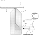
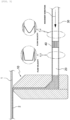
FIG. 4 is a cross-sectional view of an electrode coating apparatus in the related art, illustrating a path through which electrode slurry moves to a tip of the slot die and a flow velocity in a flow path. -
FIG. 5 is a cross-sectional view of the electrode coating apparatus according to the embodiment, illustrating a path through which electrode slurry moves to a tip of the slot die and a change in flow velocity in a flow path caused by the turbulent flow generator. -
FIG. 6A is a perspective view and a vertical cross-sectional view illustrating a turbulent flow generator having a mesh pattern according to still another embodiment, andFIG. 6B is a perspective view and a vertical cross-sectional view illustrating a turbulent flow generator having a honeycomb structure according to yet another embodiment. -
- 1: Substrate
- 2: Electrode slurry
- 10: Die coater
- 20: Injection port
- 30: Flow path
- 40 Turbulent flow generator
- 41: Minimum unit
- 50: Supply tank
- 60: Supply pipe for electrode slurry
- 100: Electrode coating apparatus
- Hereinafter, the present invention will be described in detail with reference to the drawings. However, the drawings are intended to illustratively describe the present invention, and the scope of the present invention is not limited by the drawings.
-
FIG. 1 is a schematic view illustrating an electrode coating apparatus 100. The electrode coating apparatus 100 includes asupply tank 50, adie coater 10, aninjection port 20, aflow path 30, and aturbulent flow generator 40. One end of theinjection port 20 may be fastened to the electrodeslurry flow path 30 through which electrode slurry moves from thesupply tank 50. By such fastening, aflow path 30 through which the electrode slurry moves from thesupply tank 50 to thedie coater 10 is formed, and a turbulent flow generator40 is provided in theflow path 30. -
FIG. 3 is an exploded perspective view illustrating the electrode coating apparatus 100. As illustrated inFIG. 3 , theinjection port 20 is a pipe protruding from a lateral surface of the die coater. One end of theturbulent flow generator 40 is fastened to an end of the pipe, and the other end of theturbulent flow generator 40 is fastened to an end of asupply pipe 60 for the electrode slurry. Theflow path 30 may be a path through which the electrode slurry moved from the supply pipe for the electrode slurry passes through the turbulent flow generator and is injected into the pipe. -
FIG. 2A is a perspective view and a vertical cross-sectional view illustrating the turbulent flow generator having a mesh pattern according to the embodiment, andFIG. 2B is a perspective view and a vertical cross-sectional view illustrating a turbulent flow generator having a honeycomb structure according to another embodiment. - The
turbulent flow generator 40 is provided in theflow path 30. Theturbulent flow generator 40 may be mounted as a module integrated with theflow path 30. Alternatively, theturbulent flow generator 40 may be mounted as a replaceable module and separable from theflow path 30. In particular, in case that theturbulent flow generator 40 is mounted as a replaceable module, theturbulent flow generator 40 is conveniently installed and easily replaced and maintained. In contrast, in case that theturbulent flow generator 40 is positioned in thedie coater 10, there is an inconvenience of having to disassemble and separate thedie coater 10 or replacing thedie coater 10 to replace theturbulent flow generator 40 in thedie coater 10. - The
turbulent flow generator 40 generates a turbulent flow in the electrode slurry moving along theflow path 30. Theturbulent flow generator 40 may have a shape selected to minimize a pressure drop caused by an additional structure in theflow path 30. The use of a shape, which blocks fluidity in theflow path 30, i.e., the use of a plate, which is not parallel to a flow direction, is not preferable. Specifically, theturbulent flow generator 40 may uniformize a distribution of the velocity while minimizing a pressure drop as long as theturbulent flow generator 40 may form a turbulent flow that is separated by an additional structure. The structure constituting theturbulent flow generator 40 is provided in the form of a thin metal yarn or a plate parallel to the flow direction to uniformize the distribution of the velocity while minimizing the pressure drop, such that the movingelectrode slurry 2 is affected by the edge of the plate, that is, the thickness of the plate, and the flow is divided, reducing the velocity deviation. - As illustrated in a cross-sectional view of an electrode coating apparatus in the related art in
FIG. 4 , it can be ascertained that a deviation between a flow velocity at a wall side of the flow path and a flow velocity at a central portion increases as theelectrode slurry 2 moves to the tip of the slot die. In case that the deviation between the flow velocities is large as described above, the pressure at the central portion increases, and theelectrode slurry 2 is not equally applied onto thesubstrate 1. - In contrast, the electrode coating apparatus 100 according to the present specification includes the
turbulent flow generator 40 to uniformize the distribution of the velocity of the coating material transferred to aninjection port 20 of the slot die. Specifically, as illustrated inFIG. 5 , when theelectrode slurry 2 passes through the turbulent flow generator while moving to the tip of the slot die, a turbulent flow reduces a deviation between the flow velocities, and theelectrode slurry 2 with the uniformized distribution of the velocity is more equally applied. - A cross-section of the
turbulent flow generator 40 may have a pattern having a plurality of polygons disposed adjacent to one another in a direction perpendicular to a longitudinal direction of the flow path. The polygon in the pattern, which has the plurality of polygons disposed adjacent to one another, is a figure having three or more vertices in a plan view. Specifically, the polygon may have three to ten vertices. For example, the polygon may be a triangle, a quadrangle, a pentagon, a hexagon, or the like. - The
turbulent flow generator 40 may include a plate for defining the polygon or include a metal yarn for defining the polygon. - The plate may be a metal plate. The material of the plate is not particularly limited as long as the plate may maintain sufficient strength for maintaining a shape of the plate without affecting the electrode slurry or being affected by the electrode slurry. The material of the plate may be stainless steel such as SUS304. A thickness of the plate is not particularly limited as long as the plate may maintain sufficient strength for maintaining a shape of the plate. For example, a thickness of the plate may be 0.1 mm or more and 10 mm or less.
- The material of the metal yarn is not particularly limited as long as the metal yarn may maintain sufficient strength for maintaining a shape of the metal yarn without affecting the electrode slurry or being affected by the electrode slurry. The material of the metal yarn may be stainless steel such as SUS304. A thickness of the metal yarn, i.e., a diameter of a vertical cross-section of the metal yarn in a longitudinal direction is not particularly limited as long as the metal yarn may maintain sufficient strength for maintaining a shape of the metal yarn. For example, a thickness of the metal yarn may be 0.1 mm or more and 10 mm or less.
- As illustrated in
FIG. 2 , a cross-section of theturbulent flow generator 40 may have a mesh pattern or honeycomb structure in a direction perpendicular to the longitudinal direction of the flow path. - As illustrated in
FIG. 2A , a cross-section of theturbulent flow generator 40 has a mesh pattern in the direction perpendicular to the longitudinal direction of theflow path 30. In this case, in case that a density of the mesh pattern is too high, i.e., in case that a quadrangular area of aminimum unit 41 is too small, a pressure drop increases. Therefore, a density of the mesh pattern may be low. The quadrangular area of theminimum unit 41 of the mesh pattern may be 3% or more, 4% or more, 5% or more, 6% or more, 7% or more, 8% or more, 9% or more, or 10% or more, and 20% or less, and specifically, 10% or more and 20% or less of an overall area of the cross-section of theflow path 30. In case that the above-mentioned range is satisfied, it is possible to uniformize the flow velocity by means of the turbulent flow generator while minimizing the pressure drop. In the cross-section of theflow path 30 in the longitudinal direction, the number ofminimum units 41, i.e., the number of quadrangles is ten or less. In this case, the number of minimum units is the number of closed figures that maintains the repeated quadrangular shapes. - As illustrated in
FIG. 6A , in the cross-section of theflow path 30 in the longitudinal direction, the number ofminimum units 41, i.e., the number of quadrangles may be ten. In this case, the number of minimum units is the number of closed figures that maintains the repeated quadrangular shapes. - As illustrated in
FIG. 2B , the cross-section of theturbulent flow generator 40 has a honeycomb structure in a direction perpendicular to the longitudinal direction of the flow path. In this case, in case that a density of the honeycomb structure is too high, i.e., an area of the hexagon of theminimum unit 41 is too small, a pressure drop increases. Therefore, a density of the honeycomb structure may be low. Specifically, an area of the hexagon of theminimum unit 41 of the honeycomb structure may be 3% or more, 4% or more, 5% or more, 6% or more, 7% or more, 8% or more, 9% or more, or 10% or more, and 20% or less, and specifically, 10% or more and 20% or less of the overall area of the cross-section of theflow path 30. In case that the above-mentioned range is satisfied, it is possible to uniformize the flow velocity by means of theturbulent flow generator 40 while minimizing the pressure drop. In the cross-section of theflow path 30 in the longitudinal direction, the number ofminimum units 41, i.e., the number of hexagons is ten or less. In this case, the number of minimum units is the number of closed figures that maintains the repeated hexagonal shapes. - As illustrated in
FIG. 6B , in the cross-section of theflow path 30 in the longitudinal direction, the number ofminimum units 41, i.e., the number of hexagons may be seven. In this case, the number of minimum units is the number of closed figures that maintains the repeated hexagonal shapes. - The
die coater 10 applies theelectrode slurry 2 onto thesubstrate 1. The configuration of the die coater includes a first die, a second die, and a shim provided between the first and second dies and configured to discharge the electrode slurry. Theinjection port 20 for the electrode slurry penetrates a lateral surface of at least one of the first and second dies. Theinjection port 20 may be a simple hole or protrude from the lateral surface of the die coater. Theinjection port 20 may be a pipe that penetrates the lateral surface of at least one of the first and second dies and protrudes from the lateral surface. - One end of the
injection port 20 may be fastened to the electrodeslurry supply pipe 60 through which the electrode slurry moves from thesupply tank 50. By such fastening, aflow path 30 through which the electrode slurry moves from thesupply tank 50 to thedie coater 10 is formed. In this flow path, aturbulent flow generator 40 may be provided in a pipe protruding from a lateral surface of the die coater or asupply pipe 60 for the electrode slurry. - Another embodiment of the present specification provides an electrode coating method, which uses the
die coater 10 configured to apply theelectrode slurry 2 onto thesubstrate 1, the electrode coating method including: generating a turbulent flow in a flow of the electrode slurry by allowing the electrode slurry to pass through theturbulent flow generator 40 before the electrode slurry is injected into thedie coater 10; injecting the electrode slurry, which has passed through the turbulent flow generator, into thedie coater 10; and applying, by thedie coater 10, theelectrode slurry 2 onto thesubstrate 1. - The description of the electrode coating method may be replaced with the description of the electrode coating apparatus.
- A person skilled in the art may understand that the present invention may be carried out in other specific forms without changing the technical spirit or the essential characteristics of the present invention. Therefore, it should be understood that the above-described embodiments are illustrative in all aspects and do not limit the present invention. The scope of the present invention is represented by the claims rather than the detailed description, and it should be interpreted that the meaning and scope of the claims and various embodiments derived from the equivalent concepts thereto fall within the scope of the present invention.
Claims (9)
- An electrode coating apparatus comprising:a die coater configured to apply electrode slurry onto a substrate;an injection port configured to supply the electrode slurry to the die coater;a flow path having an end coupled to the injection port so that the electrode slurry moves to the die coater; anda turbulent flow generator provided in the flow path and configured to generate a turbulent flow in the electrode slurry moving along the flow path.
- The electrode coating apparatus of claim 1, wherein a cross-section of the turbulent flow generator has a pattern having a plurality of polygons disposed adjacent to one another in a direction perpendicular to a longitudinal direction of the flow path.
- The electrode coating apparatus of claim 1, wherein a cross-section of the turbulent flow generator has a mesh pattern or a honeycomb structure in a direction perpendicular to a longitudinal direction of the flow path.
- The electrode coating apparatus of claim 2, wherein the turbulent flow generator comprises a plate that forms the polygon.
- The electrode coating apparatus of claim 2, wherein the turbulent flow generator comprises a metal yarn that forms the polygon.
- The electrode coating apparatus of claim 1, wherein the injection port is a pipe protruding from a lateral surface of the die coater,wherein one end of the turbulent flow generator is fastened to an end of the pipe, and the other end of the turbulent flow generator is fastened to an end of a supply pipe for the electrode slurry, andwherein the flow path is a path through which the electrode slurry moved from the supply pipe for the electrode slurry passes through the turbulent flow generator and is injected into the pipe.
- An electrode coating method, which uses a die coater configured to apply electrode slurry onto a substrate, the electrode coating method comprising:generating a turbulent flow in a flow of the electrode slurry by allowing the electrode slurry to pass through a turbulent flow generator before the electrode slurry is injected into the die coater;injecting the electrode slurry, which has passed through the turbulent flow generator, into the die coater; andapplying, by the die coater, the electrode slurry onto the substrate.
- The electrode coating method of claim 7, wherein a cross-section of the turbulent flow generator has a pattern having a plurality of polygons disposed adjacent to one another.
- The electrode coating method of claim 7, wherein a cross-section of the turbulent flow generator has a mesh pattern or a honeycomb structure.
Applications Claiming Priority (2)
| Application Number | Priority Date | Filing Date | Title |
|---|---|---|---|
| KR1020210153050A KR20230067200A (en) | 2021-11-09 | 2021-11-09 | Apparatus and method for coating electrode |
| PCT/KR2022/017550 WO2023085770A1 (en) | 2021-11-09 | 2022-11-09 | Apparatus and method for coating electrode |
Publications (3)
| Publication Number | Publication Date |
|---|---|
| EP4261917A1 true EP4261917A1 (en) | 2023-10-18 |
| EP4261917A4 EP4261917A4 (en) | 2024-10-02 |
| EP4261917B1 EP4261917B1 (en) | 2026-02-04 |
Family
ID=86336247
Family Applications (1)
| Application Number | Title | Priority Date | Filing Date |
|---|---|---|---|
| EP22893190.3A Active EP4261917B1 (en) | 2021-11-09 | 2022-11-09 | Apparatus and method for coating electrode |
Country Status (7)
| Country | Link |
|---|---|
| US (1) | US20240075494A1 (en) |
| EP (1) | EP4261917B1 (en) |
| JP (1) | JP7655627B2 (en) |
| KR (1) | KR20230067200A (en) |
| CN (1) | CN116801990A (en) |
| ES (1) | ES3062782T3 (en) |
| WO (1) | WO2023085770A1 (en) |
Families Citing this family (1)
| Publication number | Priority date | Publication date | Assignee | Title |
|---|---|---|---|---|
| EP4570391A1 (en) * | 2023-12-14 | 2025-06-18 | CUSTOMCELLS Holding GmbH | System for manufacturing an electrode |
Family Cites Families (16)
| Publication number | Priority date | Publication date | Assignee | Title |
|---|---|---|---|---|
| JP2005213732A (en) * | 2004-01-27 | 2005-08-11 | Chubu Shokusei:Kk | Mortar or concrete spraying apparatus |
| JP4446915B2 (en) * | 2004-08-09 | 2010-04-07 | 富士フイルム株式会社 | Dope manufacturing method and apparatus, and film forming method |
| JP2008055145A (en) * | 2006-08-03 | 2008-03-13 | Mitsuaki Kato | Method for haircutting/hairdressing and washing_water supplying apparatus therefor |
| JP4377904B2 (en) * | 2006-10-31 | 2009-12-02 | 株式会社東芝 | Electrode manufacturing method and non-aqueous electrolyte battery manufacturing method |
| US9597837B1 (en) * | 2007-11-15 | 2017-03-21 | Robocasting Enterprises, LLC | Method for making a fluidic device |
| WO2009080120A1 (en) * | 2007-12-21 | 2009-07-02 | Norgren Gmbh | Thermal flow sensor with turbulence inducers |
| KR101212201B1 (en) * | 2010-07-02 | 2012-12-13 | 삼성에스디아이 주식회사 | Active material coating apparatus |
| KR101285999B1 (en) * | 2011-04-14 | 2013-07-15 | 삼성에스디아이 주식회사 | Coating Apparatus for Electrode Plate of Secondary Battery |
| JP2013146644A (en) * | 2012-01-17 | 2013-08-01 | Toyota Motor Corp | Coating device, and method for producing electrode |
| JPWO2013121692A1 (en) * | 2012-02-17 | 2015-05-11 | パナソニックIpマネジメント株式会社 | Filler dispersion method and micro dispersion mixer |
| JP2015058368A (en) * | 2013-09-17 | 2015-03-30 | トヨタ自動車株式会社 | Coating die and coating device having the same |
| JP2016060044A (en) * | 2014-09-12 | 2016-04-25 | 富士フイルム株式会社 | Mixing apparatus and method, solution casting method |
| JP6472139B2 (en) * | 2015-06-15 | 2019-02-20 | 富士フイルム株式会社 | Orifice, liquid feeding device using the same, coating device, and optical film manufacturing method |
| US11547134B2 (en) * | 2019-03-21 | 2023-01-10 | Plant Tap, Inc. | Food and beverage product |
| EP3958357B1 (en) | 2019-04-18 | 2024-04-17 | Zeon Corporation | Binder composition for non-aqueous secondary battery electrode, slurry composition for non-aqueous secondary battery positive electrode, positive electrode for non-aqueous secondary battery, and non-aqueous secondary battery |
| CN214261426U (en) * | 2020-09-16 | 2021-09-24 | 上海威派格智慧水务股份有限公司 | Static mixing device |
-
2021
- 2021-11-09 KR KR1020210153050A patent/KR20230067200A/en active Pending
-
2022
- 2022-11-09 ES ES22893190T patent/ES3062782T3/en active Active
- 2022-11-09 WO PCT/KR2022/017550 patent/WO2023085770A1/en not_active Ceased
- 2022-11-09 EP EP22893190.3A patent/EP4261917B1/en active Active
- 2022-11-09 JP JP2023541349A patent/JP7655627B2/en active Active
- 2022-11-09 US US18/273,688 patent/US20240075494A1/en active Pending
- 2022-11-09 CN CN202280008944.6A patent/CN116801990A/en active Pending
Also Published As
| Publication number | Publication date |
|---|---|
| CN116801990A (en) | 2023-09-22 |
| ES3062782T3 (en) | 2026-04-14 |
| KR20230067200A (en) | 2023-05-16 |
| JP2024502456A (en) | 2024-01-19 |
| JP7655627B2 (en) | 2025-04-02 |
| EP4261917A4 (en) | 2024-10-02 |
| WO2023085770A1 (en) | 2023-05-19 |
| EP4261917B1 (en) | 2026-02-04 |
| US20240075494A1 (en) | 2024-03-07 |
Similar Documents
| Publication | Publication Date | Title |
|---|---|---|
| US20240222807A1 (en) | Tab plate and wound battery | |
| EP3471175A3 (en) | Negative electrode plate and secondary battery comprising the same | |
| JP7632946B2 (en) | Coating die for lithium secondary batteries including removable spacer shim | |
| KR102301210B1 (en) | Slot die for coating | |
| EP3915687B1 (en) | Slot die coating device having air vent | |
| EP3370280B1 (en) | Electrode for secondary battery having fine holes | |
| EP4261917B1 (en) | Apparatus and method for coating electrode | |
| CN102593482A (en) | Collector plate and flow battery and flow battery stack containing same | |
| CN116864600A (en) | Electrode components, battery cells, batteries and electrical devices | |
| CN202275888U (en) | Metal Bipolar Plates for Proton Exchange Membrane Fuel Cells Facilitating Improved Fluid Distribution | |
| KR20210147306A (en) | Slot die coating device | |
| KR20170067362A (en) | Slot Die for Coating of Electrode Mix Comprising Shim for Controlling Flux of Electrode Mix | |
| CN216648376U (en) | Flow battery stack structure | |
| WO2024113484A1 (en) | Electrode sheet, roller part, electrode assembly, battery cell, battery, and electric device | |
| CN102082281A (en) | Fuel cell | |
| CN207834413U (en) | A module box for placing cylindrical batteries | |
| US20220080451A1 (en) | Slot Die Coating Device Having Air Vent | |
| CN107887566B (en) | Drive control method of lithium ion flow battery system | |
| KR102089306B1 (en) | Secondary Battery Comprising Battery Case Having Fixing Protrusion Coupled to Fixing Hole of Electrode Tab in Rivet Structure | |
| KR102956337B1 (en) | Die coater | |
| EP4246604A1 (en) | Electrode slurry-supplying apparatus, coating apparatus, and die coater | |
| CN113675364A (en) | Negative plate and preparation method and application thereof | |
| KR102801794B1 (en) | Magnetic Alignment device | |
| KR102159530B1 (en) | Electrode Assembly Stack Comprising Unit Cell Having Fixing Hole | |
| CN215527906U (en) | A kind of electrolyte diversion device for lead-acid battery |
Legal Events
| Date | Code | Title | Description |
|---|---|---|---|
| STAA | Information on the status of an ep patent application or granted ep patent |
Free format text: STATUS: THE INTERNATIONAL PUBLICATION HAS BEEN MADE |
|
| PUAI | Public reference made under article 153(3) epc to a published international application that has entered the european phase |
Free format text: ORIGINAL CODE: 0009012 |
|
| STAA | Information on the status of an ep patent application or granted ep patent |
Free format text: STATUS: REQUEST FOR EXAMINATION WAS MADE |
|
| 17P | Request for examination filed |
Effective date: 20230713 |
|
| AK | Designated contracting states |
Kind code of ref document: A1 Designated state(s): AL AT BE BG CH CY CZ DE DK EE ES FI FR GB GR HR HU IE IS IT LI LT LU LV MC ME MK MT NL NO PL PT RO RS SE SI SK SM TR |
|
| A4 | Supplementary search report drawn up and despatched |
Effective date: 20240903 |
|
| RIC1 | Information provided on ipc code assigned before grant |
Ipc: B05B 1/34 20060101ALI20240828BHEP Ipc: B05C 11/10 20060101ALI20240828BHEP Ipc: B05C 5/02 20060101ALI20240828BHEP Ipc: H01M 4/04 20060101AFI20240828BHEP |
|
| DAV | Request for validation of the european patent (deleted) | ||
| DAX | Request for extension of the european patent (deleted) | ||
| STAA | Information on the status of an ep patent application or granted ep patent |
Free format text: STATUS: EXAMINATION IS IN PROGRESS |
|
| 17Q | First examination report despatched |
Effective date: 20250319 |
|
| GRAP | Despatch of communication of intention to grant a patent |
Free format text: ORIGINAL CODE: EPIDOSNIGR1 |
|
| STAA | Information on the status of an ep patent application or granted ep patent |
Free format text: STATUS: GRANT OF PATENT IS INTENDED |
|
| INTG | Intention to grant announced |
Effective date: 20251002 |
|
| P01 | Opt-out of the competence of the unified patent court (upc) registered |
Free format text: CASE NUMBER: UPC_APP_0012168_4261917/2025 Effective date: 20251105 |
|
| GRAS | Grant fee paid |
Free format text: ORIGINAL CODE: EPIDOSNIGR3 |
|
| GRAA | (expected) grant |
Free format text: ORIGINAL CODE: 0009210 |
|
| STAA | Information on the status of an ep patent application or granted ep patent |
Free format text: STATUS: THE PATENT HAS BEEN GRANTED |
|
| AK | Designated contracting states |
Kind code of ref document: B1 Designated state(s): AL AT BE BG CH CY CZ DE DK EE ES FI FR GB GR HR HU IE IS IT LI LT LU LV MC ME MK MT NL NO PL PT RO RS SE SI SK SM TR |
|
| REG | Reference to a national code |
Ref country code: CH Ref legal event code: F10 Free format text: ST27 STATUS EVENT CODE: U-0-0-F10-F00 (AS PROVIDED BY THE NATIONAL OFFICE) Effective date: 20260204 Ref country code: GB Ref legal event code: FG4D |
|
| REG | Reference to a national code |
Ref country code: DE Ref legal event code: R096 Ref document number: 602022029936 Country of ref document: DE |
|
| REG | Reference to a national code |
Ref country code: IE Ref legal event code: FG4D |
|
| REG | Reference to a national code |
Ref country code: ES Ref legal event code: FG2A Ref document number: 3062782 Country of ref document: ES Kind code of ref document: T3 Effective date: 20260414 |