EP4261719A1 - Falsification detection device, falsification detection method, and falsification detection program - Google Patents
Falsification detection device, falsification detection method, and falsification detection program Download PDFInfo
- Publication number
- EP4261719A1 EP4261719A1 EP21919304.2A EP21919304A EP4261719A1 EP 4261719 A1 EP4261719 A1 EP 4261719A1 EP 21919304 A EP21919304 A EP 21919304A EP 4261719 A1 EP4261719 A1 EP 4261719A1
- Authority
- EP
- European Patent Office
- Prior art keywords
- file
- monitoring target
- unit
- scan pattern
- tampering detection
- Prior art date
- Legal status (The legal status is an assumption and is not a legal conclusion. Google has not performed a legal analysis and makes no representation as to the accuracy of the status listed.)
- Granted
Links
Images



Classifications
-
- G—PHYSICS
- G06—COMPUTING OR CALCULATING; COUNTING
- G06F—ELECTRIC DIGITAL DATA PROCESSING
- G06F21/00—Security arrangements for protecting computers, components thereof, programs or data against unauthorised activity
- G06F21/60—Protecting data
- G06F21/64—Protecting data integrity, e.g. using checksums, certificates or signatures
-
- G—PHYSICS
- G06—COMPUTING OR CALCULATING; COUNTING
- G06F—ELECTRIC DIGITAL DATA PROCESSING
- G06F21/00—Security arrangements for protecting computers, components thereof, programs or data against unauthorised activity
- G06F21/50—Monitoring users, programs or devices to maintain the integrity of platforms, e.g. of processors, firmware or operating systems
- G06F21/55—Detecting local intrusion or implementing counter-measures
- G06F21/56—Computer malware detection or handling, e.g. anti-virus arrangements
- G06F21/562—Static detection
- G06F21/565—Static detection by checking file integrity
-
- G—PHYSICS
- G06—COMPUTING OR CALCULATING; COUNTING
- G06F—ELECTRIC DIGITAL DATA PROCESSING
- G06F21/00—Security arrangements for protecting computers, components thereof, programs or data against unauthorised activity
- G06F21/50—Monitoring users, programs or devices to maintain the integrity of platforms, e.g. of processors, firmware or operating systems
- G06F21/55—Detecting local intrusion or implementing counter-measures
- G06F21/56—Computer malware detection or handling, e.g. anti-virus arrangements
- G06F21/566—Dynamic detection, i.e. detection performed at run-time, e.g. emulation, suspicious activities
-
- G—PHYSICS
- G06—COMPUTING OR CALCULATING; COUNTING
- G06F—ELECTRIC DIGITAL DATA PROCESSING
- G06F21/00—Security arrangements for protecting computers, components thereof, programs or data against unauthorised activity
- G06F21/50—Monitoring users, programs or devices to maintain the integrity of platforms, e.g. of processors, firmware or operating systems
- G06F21/57—Certifying or maintaining trusted computer platforms, e.g. secure boots or power-downs, version controls, system software checks, secure updates or assessing vulnerabilities
-
- G—PHYSICS
- G06—COMPUTING OR CALCULATING; COUNTING
- G06F—ELECTRIC DIGITAL DATA PROCESSING
- G06F2221/00—Indexing scheme relating to security arrangements for protecting computers, components thereof, programs or data against unauthorised activity
- G06F2221/03—Indexing scheme relating to G06F21/50, monitoring users, programs or devices to maintain the integrity of platforms
- G06F2221/033—Test or assess software
Definitions
- the present invention relates to a tampering detection device, a tampering detection method, and a tampering detection program.
- the software tampering detection technique is a technique of acquiring a digest (a hash value or the like) of a monitoring target file at a certain point of time when the file can be regarded as normal, and periodically comparing the acquired digest with the current digest of the monitoring target file to check whether or not the target file has been illicitly tampered with.
- this tampering detection technique is installed in a certain device, and is used for the purpose of securing authenticity of the device by periodically scanning the entire monitoring target file in the device. As a method of this scanning, the three methods described below have been conventionally used.
- the first method is a cyclic scan method.
- the entire monitoring target file is scanned in a fixed order based on a certain rule such as ascending order of path names and node number order.
- the second method is a random scan method.
- a file to be scanned next is uniformly and randomly selected from all monitoring target files, and the file is scanned.
- the third method is an on-access scan method.
- a function of an operating system (OS) such as fanotify is utilized, an access to a file is detected and hooked, scanning is performed, and file access is permitted when tampering is not performed.
- OS operating system
- cyclic scan method which is the first method
- a file that has been scanned once is not scanned again until scanning of all the other files is completed. Therefore, in a situation where available resources such as a central processing unit (CPU) and memory are limited, a time taken until all the files are scanned in one cycle often becomes long. Thus, even when tampering is performed, it is difficult to immediately find the tampering, and there is a possibility that an authorized program executes an illicitly tampered file without noticing the tampering.
- CPU central processing unit
- the on-access scan method which is the third method
- the possibility that an authorized program unintentionally executes an illicitly tampered file can be almost completely zeroed, but monitoring and file access hooking in the OS consume considerable memory and CPU resources, and a response of an input/output (I/O) is reduced, so that an operation of the device is considerably affected.
- I/O input/output
- a tampering detection device includes: an acquisition unit that acquires an access frequency of a monitoring target file; a calculation unit that calculates a number of times of scanning in a scan pattern for each monitoring target file on the basis of the access frequency acquired by the acquisition unit; and a determination unit that determines the scan pattern on the basis of the number of times of scanning calculated by the calculation unit.
- a tampering detection method is a tampering detection method executed by a tampering detection device, the method including: an acquisition process of acquiring an access frequency of a monitoring target file; a calculation process of calculating a number of times of scanning in a scan pattern for each monitoring target file on the basis of the access frequency acquired by the acquisition process; and a determination process of determining the scan pattern on the basis of the number of times of scanning calculated by the calculation process.
- a tampering detection program causes a computer to execute: an acquisition step of acquiring an access frequency of a monitoring target file; a calculation step of calculating a number of times of scanning in a scan pattern for each monitoring target file on the basis of the access frequency acquired by the acquisition step; and a determination step of determining the scan pattern on the basis of the number of times of scanning calculated by the calculation step.
- the present invention can reduce the possibility that an authorized program executes an illicitly tampered file while suppressing use resources in a monitoring target device.
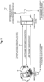
- Fig. 1 is a diagram illustrating a configuration example of the tampering detection system according to the first embodiment.
- the tampering detection system 100 includes a tampering detection device 10 such as a server and a monitoring target device 20 such as various terminals.
- the tampering detection device 10 and the monitoring target device 20 are connected to be communicable by wire or wirelessly via a predetermined communication network, which is not illustrated.
- tampering detection system 100 illustrated in Fig. 1 may include a plurality of tampering detection devices 10 and a plurality of monitoring target devices 20.
- the monitoring target device 20 transmits an access frequency, a file size, or the like of the monitoring target file to the tampering detection device 10 as information for determining a scan pattern (step S1).
- the information for determining the scan pattern is information regarding the monitoring target device ("monitoring target device information" as appropriate) and information regarding the monitoring target file ("file information" as appropriate).
- the monitoring target device information is information regarding resources of the monitoring target device or the like, and is, for example, but is not particularly limited to, information regarding a processing speed and a use amount of the CPU, a memory capacity, a storage capacity, and hash calculation, information regarding communication, and the like.
- the monitoring target device information is basic information of the monitoring target file stored in the monitoring target device or the like, and is, for example, but is not particularly limited to, a file name, a file type, a file size indicating a data size of the file, a list thereof, the number of files stored in the monitoring target device, or the like.
- the file information is information regarding access of the monitoring target file stored in the monitoring target device or the like, and includes, for example, information acquired or calculated by the tampering detection device 10 in addition to information such as the number of times of access, an access frequency, and an access source for each file included in an access log, but is not particularly limited thereto.
- the tampering detection device 10 determines a scan pattern on the basis of the acquired access frequency or the like (step S2).
- the scan pattern indicates an order of one cycle of processing (scan processing) in which the monitoring target device 20 generates a digest of each file ("file digest" as appropriate) for the monitoring target file stored in the monitoring target device 20, but is not particularly limited thereto.
- the scan pattern may indicate a time, an interval, or the like at which each scan processing is performed.
- the digest of the file generated by the monitoring target device 20 is, but particularly not limited to, data generated through hash calculation or the like.
- the tampering detection device 10 can determine the scan pattern not including a specific file by static or dynamic setting. Detailed scan pattern determination processing by the tampering detection device 10 will be described below in [Flow of Scan Pattern Determination Processing] .
- the tampering detection device 10 transmits the determined scan pattern to the monitoring target device 20 (step S3). Then, the monitoring target device 20 generates the digest of the file according to the acquired scan pattern (step S4). Further, the monitoring target device 20 transmits the generated digest of the file to the tampering detection device 10 (step S5).
- the tampering detection device 10 verifies whether the file has been tampered with on basis of the acquired digest of the file (step S6). At this time, the tampering detection device 10 compares the digest of the correct file stored in the tampering detection device 10 with the acquired digest of the file, and determines that the file has been tampered with when the digests are different.
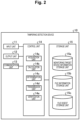
- Fig. 2 is a block diagram illustrating a configuration example of the tampering detection device according to the present embodiment.
- the tampering detection device 10 includes an input unit 11, an output unit 12, a communication unit 13, a control unit 14, and a storage unit 15.
- the input unit 11 controls inputting various types of information to the tampering detection device 10.
- the input unit 11 is, for example, a mouse, a keyboard, or the like, and accepts input of setting information or the like to the tampering detection device 10.
- the output unit 12 controls outputting various types of information from the tampering detection device 10.
- the output unit 12 is, for example, a display or the like and outputs the setting information or the like stored in the tampering detection device 10.
- the communication unit 13 controls data communication with other devices. For example, the communication unit 13 performs data communication with each communication device. In addition, the communication unit 13 can perform data communication with a terminal of an operator, which is not illustrated.
- the storage unit 15 stores various types of information referred to when the control unit 14 operates and various types of information acquired when the control unit 14 operates.
- the storage unit 15 includes a monitoring target device information storage unit 15a, a file information storage unit 15b, and a file digest storage unit 15c.
- the storage unit 15 is, for example, a semiconductor memory element such as random access memory (RAM) or flash memory, a storage device such as a hard disk, an optical disc, or the like. Note that, in the example of Fig. 2 , the storage unit 15 is installed inside the tampering detection device 10, but may be installed outside the tampering detection device 10, or a plurality of storage units may be installed.
- the monitoring target device information storage unit 15a stores monitoring target device information such as information regarding resources of the monitoring target device acquired by an acquisition unit 14a of the control unit 14 and basic information of the monitoring target file.
- the monitoring target device information storage unit 15a stores, for example, information regarding a processing speed of the CPU, a memory capacity, a storage capacity, and hash calculation as information regarding resources of the monitoring target device, and stores a file name of the file, a file type, a file size indicating a data size of the file, a list thereof, the number of files stored in the monitoring target device, and the like as basic information of the monitoring target file.
- the file information storage unit 15b stores, as file information, information included in the access log acquired by the acquisition unit 14a of the control unit 14.
- the file information storage unit 15b stores information such as the number of times of access, an access frequency, and an access source for each file as information included in the access log described above.
- the file information storage unit 15b may store the time ("scan pattern set time" as appropriate) ⁇ all for one scan processing cycle acquired by the acquisition unit 14a.
- the file information storage unit 15b stores information calculated by a calculation unit 14b of the control unit 14 as file information.
- the file information storage unit 15b stores, as the information calculated by the calculation unit 14b described above, the time ("time required for hash calculation" as appropriate) ⁇ i required to calculate the hash value of a file i and the number of times of scanning k i in the scan pattern for each monitoring target file that minimizes an evaluation index E[ ⁇ attack ] to be described below.
- the file information storage unit 15b may store the scan pattern determined by a determination unit 14c.
- the file digest storage unit 15c stores information regarding a correct monitoring target file for verifying tampering acquired by the acquisition unit 14a of the control unit 14.
- the file digest storage unit 15c stores a file digest generated using hash calculation from a file stored in the monitoring target device as information regarding a correct monitoring target file for verifying tampering.
- the control unit 14 controls the entire tampering detection device 10.
- the control unit 14 includes the acquisition unit 14a, the calculation unit 14b, the determination unit 14c, a transmission unit 14d, and a verification unit 14e.
- the control unit 14 is, for example, an electronic circuit such as a CPU or a micro processing unit (MPU), or an integrated circuit such as an application specific integrated circuit (ASIC) or a field programmable gate array (FPGA).
- the acquisition unit 14a acquires the access frequency of the monitoring target file. For example, the acquisition unit 14a acquires the access frequency from the monitoring target device 20 that stores the monitoring target file. In addition, the acquisition unit 14a acquires the access frequency included in the access log of the monitoring target file of the monitoring target device 20. In addition, the acquisition unit 14a acquires the file size of the monitoring target file and the scan pattern set time. In addition, the acquisition unit 14a calculates and acquires a time required for hash calculation for each file from the acquired file size. Further, the acquisition unit 14a acquires the digest of the file generated by the monitoring target device 20.
- the acquisition unit 14a stores the acquired monitoring target device information such as resources of the monitoring target device 20 in the monitoring target device information storage unit 15a.
- the acquisition unit 14a stores the acquired file information such as the access frequency in the file information storage unit 15b. Further, the acquisition unit 14a transmits the acquired digest of the file to the verification unit 15e.
- the calculation unit 14b calculates the number of times of scanning in the scan pattern for each monitoring target file on the basis of the access frequency acquired by the acquisition unit 14a. For example, the calculation unit 14b calculates the number of times of scanning in the scan pattern for each monitoring target file on the basis of the access frequency, the file size, and the scan pattern set time acquired by the acquisition unit 14a. In addition, the calculation unit 14b calculates, for each monitoring target file, the number of times of scanning in the scan pattern that minimizes an average time from scanning of the monitoring target file to the latest access. On the other hand, the calculation unit 14b stores the file information such as the calculated number of times of scanning in the file information storage unit 15b. Note that detailed calculation processing of the information acquired by the tampering detection device 10 will be described below in [Flow of Scan Pattern Determination Processing].
- the determination unit 14c determines a scan pattern on the basis of the number of times of scanning calculated by the calculation unit 14b. In addition, the determination unit 14c randomly determines a scan pattern in which all the monitoring target files are included at least once on the basis of the number of times of scanning calculated by the calculation unit 14b. At this time, the determination unit 14c refers to the monitoring target device information stored in the monitoring target device information storage unit 15a. In addition, the determination unit 14c refers to the file information stored in the file information storage unit 15b. Note that detailed scan pattern determination processing by the tampering detection device 10 will be described below in [Flow of Scan Pattern Determination Processing].
- the transmission unit 14d transmits the scan pattern determined by the determination unit 14c to the monitoring target device 20.
- the transmission unit 14d may transmit whether the file verified by the verification unit 14e has been tampered with to the monitoring target device 20 or another terminal.
- the verification unit 14e verifies whether the file has been tampered with by using the digest of the file generated on the basis of the scan pattern by the monitoring target device 20. At this time, the verification unit 14e refers to the file digest of the correct monitoring target file stored in the file digest storage unit 15c.
- FIG. 3 is a block diagram illustrating a configuration example of a monitoring target device according to the present embodiment.
- the monitoring target device 20 includes an input unit 21, an output unit 22, a communication unit 23, a control unit 24, and a storage unit 25.
- the input unit 21 controls inputting various types of information to the monitoring target device 20.
- the input unit 21 is, for example, a mouse, a keyboard, or the like, and accepts input of setting information or the like to the monitoring target device 20.
- the output unit 22 controls outputting various types of information from the monitoring target device 20.
- the output unit 22 is, for example, a display or the like and outputs the setting information or the like stored in the monitoring target device 20.
- the communication unit 23 controls data communication with other devices. For example, the communication unit 23 performs data communication with each communication device. In addition, the communication unit 23 can perform data communication with a terminal of an operator, which is not illustrated.
- the storage unit 25 stores various types of information referred to when the control unit 24 operates and various types of information acquired when the control unit 24 operates.
- the storage unit 25 includes, for example, a monitoring target file storage unit 25a.
- the storage unit 25 is, for example, a semiconductor memory element such as RAM or flash memory, or a storage device such as a hard disk or an optical disc. Note that, in the example of Fig. 3 , the storage unit 25 is installed inside the monitoring target device 20, but may be installed outside the monitoring target device 20, or a plurality of storage units may be installed.
- the monitoring target file storage unit 25a stores a monitoring target file that can be accessed from the outside or tampered with.
- the control unit 24 controls the entire monitoring target device 20.
- the control unit 24 includes an acquisition unit 24a, a generation unit 24b, and a transmission unit 24c.
- the control unit 24 is, for example, an electronic circuit such as a CPU or an MPU, or an integrated circuit such as an ASIC or an FPGA.
- the acquisition unit 24a acquires a scan pattern of files from the tampering detection device 10. In addition, the acquisition unit 24a may acquire information regarding whether or not the file has been tampered with from the tampering detection device 10.
- the generation unit 24b generates the digest of the file according to the scan pattern of the file acquired by the acquisition unit 24a. In addition, the generation unit 24b may store the generated digest of the file in the storage unit 25.
- the transmission unit 24c transmits the digest of the file generated by the generation unit 24b to the tampering detection device 10. In addition, the transmission unit 24c may transmit the digest of the file to a terminal other than the tampering detection device 10.
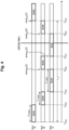
- Fig. 4 is a diagram for describing a definition of each constant according to the first embodiment.
- N files ⁇ 1, 2, ..., N ⁇ of a monitoring target file group in the monitoring target device 20 there are N files ⁇ 1, 2, ..., N ⁇ of a monitoring target file group in the monitoring target device 20, and an i-th file is referred to as a file i.
- ⁇ i represents a time required for hash calculation of the file i, and a numerical value thereof is obtained by Formula (1).
- ⁇ av represents an average time required for hash calculation of the file, and a numerical value thereof is obtained by Formula (2) .
- Formula (3) represents a scan pattern for the file i.
- s i j represents a j-th scan start time for the file i
- k i represents the number of times of scanning in the scan pattern for the file i, that is, the number of times of scanning per scan processing cycle.
- Fig. 4 illustrates first scan start times of the first and second cycles for "file A”, first to third scan start times of the first cycle for "file B", and first and second scan start times of the first cycle for "file C”.
- “next i (t)” is a time at which scanning of the file i is started for the first time after a certain time t, and is determined by a scan pattern. Note that, in Fig. 4 , “next i (t)” is illustrated for each of scans of "file A” and “file B” after a certain time t.
- prev i (t) is a time at which scanning of the file i is started immediately before a certain time t, and is determined by a scan pattern. Note that, in Fig. 4 , “prev i (t)” is illustrated for each of scans of "file B" and “file C” immediately before a certain time t.
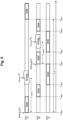
- Fig. 5 is a diagram for describing an evaluation index of a scan pattern according to the first embodiment.
- E[ ⁇ attack ] is introduced as an evaluation index for determining whether a scan pattern is good or bad in order to formulate a "possibility that an authorized program unintentionally executes an illicitly tampered file".
- the definition and optimization of the evaluation index E[ ⁇ attack ] will be described.
- ⁇ attack represents a time until another process uses the file i after the file i is scanned, that is, a time from scanning to the latest access, and a numerical value thereof is obtained by Formula (5).
- t access is a time at which the file i is read by another process, that is, a time at which the file i is accessed, and it is assumed that all accesses occur instantaneously without time width.
- q i (t) represents a probability that an access to the file i occurs at a certain time t.
- the evaluation index E[ ⁇ attack ] represents an average time until another process reads the monitoring target file after scanning, that is, an average time from scanning of the monitoring target file to the latest access, and is expressed by Formula (6) .
- the evaluation index E[ ⁇ attack ] can also be defined as "an unprotected time of the monitoring target file" or "a tamperable time of the monitoring target file”.
- E ⁇ attack 1 N ⁇ i ⁇ t ⁇ prev i t q i t dt
- E[ ⁇ attack ] can be expressed as Formula (9) .
- E ⁇ attack ⁇ 1 N ⁇ i q i k i
- the optimization of the evaluation index E[ ⁇ attack ] is a method of "generating a random scan pattern in which scan is performed more frequently as access frequency of file is higher in consideration of time required for scan according to file size".
- Fig. 6 is a flowchart illustrating an example of a flow of tampering detection processing according to the first embodiment.
- the acquisition unit 14a of the tampering detection device 10 acquires information such as information of an access frequency and a file size of a monitoring target file from the monitoring target device 20 (step S101).
- the acquisition unit 14a may acquire the information from a device other than the monitoring target device 20.
- the acquisition unit 14a may acquire information directly input via the input unit 11.
- the determination unit 14c determines an optimum scan pattern on the basis of the information acquired from the monitoring target device 20 such as access frequency (step S102).
- the calculation unit 14b may perform calculation processing for information necessary for the determination unit 14c to determine the scan pattern.
- the determination unit 14c can also adopt this scan pattern.
- the determination unit 14c can adopt one or a plurality of scan patterns from the scan patterns.
- the transmission unit 14d transmits the scan pattern to the monitoring target device 20 (step S103).
- the transmission unit 14d may transmit the scan patterns in bulk (collectively) or may transmit the scan patterns one by one.
- the transmission unit 14d may transmit a plurality of scan patterns.
- the acquisition unit 14a acquires a digest of a file generated by the generation unit 24b of the monitoring target device 20 and transmitted by the transmission unit 24c (step S104).
- the verification unit 14e verifies whether the file has been tampered with on the basis of the digest of the file acquired by the acquisition unit 14a (step S105), and the tampering detection processing ends.
- the transmission unit 14d may transmit whether the file has been tampered with verified by the verification unit 14e to the monitoring target device 20 or another terminal.
- Fig. 7 is a flowchart illustrating an example of a flow of scan pattern determination processing according to the first embodiment.
- the acquisition unit 14a of the tampering detection device 10 acquires an access log of a monitoring target file in the monitoring target device 20 for a certain period from the monitoring target device 20 (step S201), and acquires an access frequency for each monitoring target file from the access log (step S202).
- the acquisition unit 14a may acquire the access log from a device other than the monitoring target device 20.
- the acquisition unit 14a may acquire the access log directly input via the input unit 11. Note that in a certain period regarding the acquisition of the access log, the monitoring target device 20 may perform the scan processing by an arbitrary method or may not perform the scan processing.
- the acquisition unit 14a of the tampering detection device 10 acquires the file size of the monitoring target file from the monitoring target device 20 (step S203). At this time, the acquisition unit 14a may acquire the file size from a device other than the monitoring target device 20. In addition, the acquisition unit 14a may acquire the file size directly input via the input unit 11.
- the acquisition unit 14a calculates and acquires a time ⁇ i required for hash calculation for each file from the file size described above and the like (step S204). Note that the acquisition unit 14a uses above Formula (1) when calculating ⁇ i described above. In addition, the acquisition unit 14a may calculate and acquire an average time ⁇ av required for hash calculation of the file represented by Formula (2) described above.
- the acquisition unit 14a acquires a set time ⁇ all of one scan processing cycle (step S205).
- ⁇ all is a numerical value given as a set value from the outside, but is not particularly limited.
- the acquisition unit 14a may acquire ⁇ all from the monitoring target device 20 or another terminal, or may acquire ⁇ all directly input via the input unit 11.
- steps S201 to S205 are exemplary, and the acquisition unit 14a can also perform the processing in a different order. In addition, the acquisition unit 14a can omit part of the processing of steps S201 to S205.
- the calculation unit 14b calculates the number of times of scanning k i of one cycle that minimizes the evaluation index E[ ⁇ attack ] using acquired ⁇ i and ⁇ all (step S206). At this time, when it is desired to generate a scan pattern so as to scan all the files at least once in one cycle, the calculation unit 14b sets the minimum value of k i for an arbitrary file to one (step S207). Finally, the determination unit 14c randomly determines a scan pattern that satisfies k i (step S208), and the processing ends.
- the access frequency of the monitoring target file is acquired, the number of times of scanning in the scan pattern is calculated for each monitoring target file on the basis of the acquired access frequency, and the scan pattern is determined on the basis of the calculated number of times of scanning.
- the file size of the monitoring target file and the scan pattern set time are further acquired, and the number of times of scanning is calculated on the basis of the access frequency, the file size, and the set time.
- the number of times of scanning that minimizes an average time from scanning of the monitoring target file to the latest access is calculated.
- a scan pattern in which all the monitoring target files are included at least once is randomly determined on the basis of the number of times of scanning.
- the access frequency is acquired from the monitoring target device that stores the monitoring target file, the scan pattern is transmitted to the monitoring target device, and whether or not the file has been tampered with is verified using the digest of the file generated on the basis of the scan pattern by the monitoring target device.
- each component of each device that has been illustrated according to the embodiment described above is functionally conceptual and does not necessarily have to be physically configured as illustrated.
- a specific form of distribution and integration of individual devices is not limited to the illustrated form, and all or part of the configuration can be functionally or physically distributed and integrated in any unit according to various loads, usage conditions, and the like.
- all or any part of each processing function performed in each device can be implemented by a CPU and a program to be analyzed and executed by the CPU or can be implemented as hardware by wired logic.
- Fig. 8 is a diagram illustrating a computer that executes a program.
- a computer 1000 includes, for example, memory 1010, a CPU 1020, a hard disk drive interface 1030, a disk drive interface 1040, a serial port interface 1050, a video adapter 1060, and a network interface 1070. These units are connected by a bus 1080.
- the memory 1010 includes a read only memory (ROM) 1011 and a RAM 1012.
- the ROM 1011 stores, for example, a boot program such as a basic input output system (BIOS).
- BIOS basic input output system
- the hard disk drive interface 1030 is connected to a hard disk drive 1090 as exemplified in Fig. 8 .
- the disk drive interface 1040 is connected to a disk drive 1100 as exemplified in Fig. 8 .
- a removable storage medium such as a magnetic disk or an optical disk is inserted into the disk drive 1100.
- the serial port interface 1050 is connected to, for example, a mouse 1110 and a keyboard 1120.
- the video adapter 1060 is connected to, for example, a display 1130.
- the hard disk drive 1090 stores, for example, an OS 1091, an application program 1092, a program module 1093, and program data 1094.
- the above program is stored, for example, in the hard disk drive 1090 as a program module in which a command to be executed by the computer 1000 is described.
- various data described in the embodiment described above is stored as program data in, for example, the memory 1010 and the hard disk drive 1090.
- the CPU 1020 reads out the program module 1093 and the program data 1094 stored in the memory 1010 and the hard disk drive 1090 to the RAM 1012 as necessary and executes various processing procedures.
- program module 1093 and the program data 1094 related to the program are not limited to being stored in the hard disk drive 1090 and may be stored in, for example, a removable storage medium and may be read by the CPU 1020 via a disk drive, or the like.
- the program module 1093 and the program data 1094 related to the program may be stored in another computer connected via a network (such as a local area network (LAN) or a wide area network (WAN)) and may be read by the CPU 1020 via the network interface 1070.
- LAN local area network
- WAN wide area network
Landscapes
- Engineering & Computer Science (AREA)
- Computer Security & Cryptography (AREA)
- Theoretical Computer Science (AREA)
- Software Systems (AREA)
- Computer Hardware Design (AREA)
- General Engineering & Computer Science (AREA)
- General Physics & Mathematics (AREA)
- Physics & Mathematics (AREA)
- Health & Medical Sciences (AREA)
- General Health & Medical Sciences (AREA)
- Virology (AREA)
- Bioethics (AREA)
- Storage Device Security (AREA)
- Burglar Alarm Systems (AREA)
- Inspection Of Paper Currency And Valuable Securities (AREA)
Abstract
Description
- The present invention relates to a tampering detection device, a tampering detection method, and a tampering detection program.
- The software tampering detection technique is a technique of acquiring a digest (a hash value or the like) of a monitoring target file at a certain point of time when the file can be regarded as normal, and periodically comparing the acquired digest with the current digest of the monitoring target file to check whether or not the target file has been illicitly tampered with. In general, this tampering detection technique is installed in a certain device, and is used for the purpose of securing authenticity of the device by periodically scanning the entire monitoring target file in the device. As a method of this scanning, the three methods described below have been conventionally used.
- The first method is a cyclic scan method. In this method, the entire monitoring target file is scanned in a fixed order based on a certain rule such as ascending order of path names and node number order.
- The second method is a random scan method. In this method, a file to be scanned next is uniformly and randomly selected from all monitoring target files, and the file is scanned.
- The third method is an on-access scan method. In this method, a function of an operating system (OS) such as fanotify is utilized, an access to a file is detected and hooked, scanning is performed, and file access is permitted when tampering is not performed.
-
- Patent Literature 1:
JP 2019-008376 A - Patent Literature 2:
JP 2019-008732 A - Patent Literature 3:
JP 2019-207661 A - However, in the conventional technique, it is not possible to reduce the possibility that an authorized program executes an illicitly tampered file while suppressing use resources in a monitoring target device. This is because the above-described three scan methods have the problems described below.
- In the cyclic scan method, which is the first method, a file that has been scanned once is not scanned again until scanning of all the other files is completed. Therefore, in a situation where available resources such as a central processing unit (CPU) and memory are limited, a time taken until all the files are scanned in one cycle often becomes long. Thus, even when tampering is performed, it is difficult to immediately find the tampering, and there is a possibility that an authorized program executes an illicitly tampered file without noticing the tampering.
- In the random scan method, which is the second method, since a file to be scanned is selected completely randomly, there is a possibility that it takes an enormous amount of time from when a certain file is scanned to when the file is scanned next.
- In the on-access scan method, which is the third method, the possibility that an authorized program unintentionally executes an illicitly tampered file can be almost completely zeroed, but monitoring and file access hooking in the OS consume considerable memory and CPU resources, and a response of an input/output (I/O) is reduced, so that an operation of the device is considerably affected.
- In order to solve the above-described problems and achieve the object, a tampering detection device according to the present invention includes: an acquisition unit that acquires an access frequency of a monitoring target file; a calculation unit that calculates a number of times of scanning in a scan pattern for each monitoring target file on the basis of the access frequency acquired by the acquisition unit; and a determination unit that determines the scan pattern on the basis of the number of times of scanning calculated by the calculation unit.
- In addition, a tampering detection method according to the present invention is a tampering detection method executed by a tampering detection device, the method including: an acquisition process of acquiring an access frequency of a monitoring target file; a calculation process of calculating a number of times of scanning in a scan pattern for each monitoring target file on the basis of the access frequency acquired by the acquisition process; and a determination process of determining the scan pattern on the basis of the number of times of scanning calculated by the calculation process.
- In addition, a tampering detection program according to the present invention causes a computer to execute: an acquisition step of acquiring an access frequency of a monitoring target file; a calculation step of calculating a number of times of scanning in a scan pattern for each monitoring target file on the basis of the access frequency acquired by the acquisition step; and a determination step of determining the scan pattern on the basis of the number of times of scanning calculated by the calculation step.
- The present invention can reduce the possibility that an authorized program executes an illicitly tampered file while suppressing use resources in a monitoring target device.
-
-
Fig. 1 is a diagram illustrating a configuration example of a tampering detection system according to a first embodiment. -
Fig. 2 is a block diagram illustrating a configuration example of a tampering detection device according to the first embodiment. -
Fig. 3 is a block diagram illustrating a configuration example of a monitoring target device according to the first embodiment. -
Fig. 4 is a diagram for describing a definition of each constant according to the first embodiment. -
Fig. 5 is a diagram for describing an evaluation index of a scan pattern according to the first embodiment. -
Fig. 6 is a flowchart illustrating an example of a flow of tampering detection processing according to the first embodiment. -
Fig. 7 is a flowchart illustrating an example of a flow of scan pattern determination processing according to the first embodiment. -
Fig. 8 is a diagram illustrating a computer that executes a program. - Hereinafter, an embodiment of a tampering detection device, a tampering detection method, and a tampering detection program according to the present invention will be described in detail with reference to the drawings. Note that the present invention is not limited to the embodiment described below.
- Hereinafter, a configuration of a tampering detection system, a configuration of a tampering detection device, a configuration of a monitoring target device, the definition of each constant, an evaluation index of a scan pattern, a flow of tampering detection processing, and a flow of scan pattern determination processing according to the present embodiment will be described in order, and finally, the effects of the present embodiment will be described.
- A configuration of a tampering detection system (appropriately referred to as the present system) 100 according to the present embodiment will be described in detail with reference to
Fig. 1. Fig. 1 is a diagram illustrating a configuration example of the tampering detection system according to the first embodiment. Thetampering detection system 100 includes atampering detection device 10 such as a server and amonitoring target device 20 such as various terminals. Here, thetampering detection device 10 and themonitoring target device 20 are connected to be communicable by wire or wirelessly via a predetermined communication network, which is not illustrated. Note thattampering detection system 100 illustrated inFig. 1 may include a plurality oftampering detection devices 10 and a plurality of monitoringtarget devices 20. - First, the
monitoring target device 20 transmits an access frequency, a file size, or the like of the monitoring target file to thetampering detection device 10 as information for determining a scan pattern (step S1). Here, the information for determining the scan pattern is information regarding the monitoring target device ("monitoring target device information" as appropriate) and information regarding the monitoring target file ("file information" as appropriate). - The monitoring target device information is information regarding resources of the monitoring target device or the like, and is, for example, but is not particularly limited to, information regarding a processing speed and a use amount of the CPU, a memory capacity, a storage capacity, and hash calculation, information regarding communication, and the like. In addition, the monitoring target device information is basic information of the monitoring target file stored in the monitoring target device or the like, and is, for example, but is not particularly limited to, a file name, a file type, a file size indicating a data size of the file, a list thereof, the number of files stored in the monitoring target device, or the like.
- The file information is information regarding access of the monitoring target file stored in the monitoring target device or the like, and includes, for example, information acquired or calculated by the
tampering detection device 10 in addition to information such as the number of times of access, an access frequency, and an access source for each file included in an access log, but is not particularly limited thereto. - Next, the
tampering detection device 10 determines a scan pattern on the basis of the acquired access frequency or the like (step S2). Here, the scan pattern indicates an order of one cycle of processing (scan processing) in which themonitoring target device 20 generates a digest of each file ("file digest" as appropriate) for the monitoring target file stored in themonitoring target device 20, but is not particularly limited thereto. The scan pattern may indicate a time, an interval, or the like at which each scan processing is performed. - Note that the digest of the file generated by the
monitoring target device 20 is, but particularly not limited to, data generated through hash calculation or the like. In addition, thetampering detection device 10 can determine the scan pattern not including a specific file by static or dynamic setting. Detailed scan pattern determination processing by thetampering detection device 10 will be described below in [Flow of Scan Pattern Determination Processing] . - Subsequently, the
tampering detection device 10 transmits the determined scan pattern to the monitoring target device 20 (step S3). Then, themonitoring target device 20 generates the digest of the file according to the acquired scan pattern (step S4). Further, themonitoring target device 20 transmits the generated digest of the file to the tampering detection device 10 (step S5). - Finally, the
tampering detection device 10 verifies whether the file has been tampered with on basis of the acquired digest of the file (step S6). At this time, thetampering detection device 10 compares the digest of the correct file stored in thetampering detection device 10 with the acquired digest of the file, and determines that the file has been tampered with when the digests are different. - The
tampering detection system 100 according to the present embodiment acquires a file access log and the file size of a monitoring target file from the monitoring target device, calculates a time required for scanning a target file (= digest acquisition) from the file size on the basis of these pieces of information, and generates a scan pattern in consideration of the time required for scanning for each file and the frequency of access to the target file. Therefore, it is possible to reduce the possibility that an authorized program executes an illicitly tampered file while suppressing use resources in a device. - A configuration of the
tampering detection device 10 according to the present embodiment will be described in detail with reference toFig. 2. Fig. 2 is a block diagram illustrating a configuration example of the tampering detection device according to the present embodiment. Thetampering detection device 10 includes an input unit 11, anoutput unit 12, a communication unit 13, acontrol unit 14, and astorage unit 15. - The input unit 11 controls inputting various types of information to the
tampering detection device 10. The input unit 11 is, for example, a mouse, a keyboard, or the like, and accepts input of setting information or the like to thetampering detection device 10. In addition, theoutput unit 12 controls outputting various types of information from thetampering detection device 10. Theoutput unit 12 is, for example, a display or the like and outputs the setting information or the like stored in thetampering detection device 10. - The communication unit 13 controls data communication with other devices. For example, the communication unit 13 performs data communication with each communication device. In addition, the communication unit 13 can perform data communication with a terminal of an operator, which is not illustrated.
- The
storage unit 15 stores various types of information referred to when thecontrol unit 14 operates and various types of information acquired when thecontrol unit 14 operates. Thestorage unit 15 includes a monitoring target deviceinformation storage unit 15a, a fileinformation storage unit 15b, and a file digeststorage unit 15c. Here, thestorage unit 15 is, for example, a semiconductor memory element such as random access memory (RAM) or flash memory, a storage device such as a hard disk, an optical disc, or the like. Note that, in the example ofFig. 2 , thestorage unit 15 is installed inside thetampering detection device 10, but may be installed outside thetampering detection device 10, or a plurality of storage units may be installed. - The monitoring target device
information storage unit 15a stores monitoring target device information such as information regarding resources of the monitoring target device acquired by anacquisition unit 14a of thecontrol unit 14 and basic information of the monitoring target file. The monitoring target deviceinformation storage unit 15a stores, for example, information regarding a processing speed of the CPU, a memory capacity, a storage capacity, and hash calculation as information regarding resources of the monitoring target device, and stores a file name of the file, a file type, a file size indicating a data size of the file, a list thereof, the number of files stored in the monitoring target device, and the like as basic information of the monitoring target file. - The file
information storage unit 15b stores, as file information, information included in the access log acquired by theacquisition unit 14a of thecontrol unit 14. For example, the fileinformation storage unit 15b stores information such as the number of times of access, an access frequency, and an access source for each file as information included in the access log described above. Further, the fileinformation storage unit 15b may store the time ("scan pattern set time" as appropriate) τall for one scan processing cycle acquired by theacquisition unit 14a. - In addition, the file
information storage unit 15b stores information calculated by acalculation unit 14b of thecontrol unit 14 as file information. For example, the fileinformation storage unit 15b stores, as the information calculated by thecalculation unit 14b described above, the time ("time required for hash calculation" as appropriate) τi required to calculate the hash value of a file i and the number of times of scanning ki in the scan pattern for each monitoring target file that minimizes an evaluation index E[τattack] to be described below. Further, the fileinformation storage unit 15b may store the scan pattern determined by a determination unit 14c. - The file digest
storage unit 15c stores information regarding a correct monitoring target file for verifying tampering acquired by theacquisition unit 14a of thecontrol unit 14. For example, the file digeststorage unit 15c stores a file digest generated using hash calculation from a file stored in the monitoring target device as information regarding a correct monitoring target file for verifying tampering. - The
control unit 14 controls the entiretampering detection device 10. Thecontrol unit 14 includes theacquisition unit 14a, thecalculation unit 14b, the determination unit 14c, atransmission unit 14d, and averification unit 14e. Here, thecontrol unit 14 is, for example, an electronic circuit such as a CPU or a micro processing unit (MPU), or an integrated circuit such as an application specific integrated circuit (ASIC) or a field programmable gate array (FPGA). - The
acquisition unit 14a acquires the access frequency of the monitoring target file. For example, theacquisition unit 14a acquires the access frequency from themonitoring target device 20 that stores the monitoring target file. In addition, theacquisition unit 14a acquires the access frequency included in the access log of the monitoring target file of themonitoring target device 20. In addition, theacquisition unit 14a acquires the file size of the monitoring target file and the scan pattern set time. In addition, theacquisition unit 14a calculates and acquires a time required for hash calculation for each file from the acquired file size. Further, theacquisition unit 14a acquires the digest of the file generated by themonitoring target device 20. - On the other hand, the
acquisition unit 14a stores the acquired monitoring target device information such as resources of themonitoring target device 20 in the monitoring target deviceinformation storage unit 15a. In addition, theacquisition unit 14a stores the acquired file information such as the access frequency in the fileinformation storage unit 15b. Further, theacquisition unit 14a transmits the acquired digest of the file to the verification unit 15e. - The
calculation unit 14b calculates the number of times of scanning in the scan pattern for each monitoring target file on the basis of the access frequency acquired by theacquisition unit 14a. For example, thecalculation unit 14b calculates the number of times of scanning in the scan pattern for each monitoring target file on the basis of the access frequency, the file size, and the scan pattern set time acquired by theacquisition unit 14a. In addition, thecalculation unit 14b calculates, for each monitoring target file, the number of times of scanning in the scan pattern that minimizes an average time from scanning of the monitoring target file to the latest access. On the other hand, thecalculation unit 14b stores the file information such as the calculated number of times of scanning in the fileinformation storage unit 15b. Note that detailed calculation processing of the information acquired by thetampering detection device 10 will be described below in [Flow of Scan Pattern Determination Processing]. - The determination unit 14c determines a scan pattern on the basis of the number of times of scanning calculated by the
calculation unit 14b. In addition, the determination unit 14c randomly determines a scan pattern in which all the monitoring target files are included at least once on the basis of the number of times of scanning calculated by thecalculation unit 14b. At this time, the determination unit 14c refers to the monitoring target device information stored in the monitoring target deviceinformation storage unit 15a. In addition, the determination unit 14c refers to the file information stored in the fileinformation storage unit 15b. Note that detailed scan pattern determination processing by thetampering detection device 10 will be described below in [Flow of Scan Pattern Determination Processing]. - The
transmission unit 14d transmits the scan pattern determined by the determination unit 14c to themonitoring target device 20. In addition, thetransmission unit 14d may transmit whether the file verified by theverification unit 14e has been tampered with to themonitoring target device 20 or another terminal. - The
verification unit 14e verifies whether the file has been tampered with by using the digest of the file generated on the basis of the scan pattern by themonitoring target device 20. At this time, theverification unit 14e refers to the file digest of the correct monitoring target file stored in the file digeststorage unit 15c. - A configuration of the
monitoring target device 20 according to the present embodiment will be described in detail with reference toFig. 3. Fig. 3 is a block diagram illustrating a configuration example of a monitoring target device according to the present embodiment. Themonitoring target device 20 includes an input unit 21, an output unit 22, acommunication unit 23, a control unit 24, and astorage unit 25. - The input unit 21 controls inputting various types of information to the
monitoring target device 20. The input unit 21 is, for example, a mouse, a keyboard, or the like, and accepts input of setting information or the like to themonitoring target device 20. In addition, the output unit 22 controls outputting various types of information from themonitoring target device 20. The output unit 22 is, for example, a display or the like and outputs the setting information or the like stored in themonitoring target device 20. - The
communication unit 23 controls data communication with other devices. For example, thecommunication unit 23 performs data communication with each communication device. In addition, thecommunication unit 23 can perform data communication with a terminal of an operator, which is not illustrated. - The
storage unit 25 stores various types of information referred to when the control unit 24 operates and various types of information acquired when the control unit 24 operates. Thestorage unit 25 includes, for example, a monitoring target file storage unit 25a. Here, thestorage unit 25 is, for example, a semiconductor memory element such as RAM or flash memory, or a storage device such as a hard disk or an optical disc. Note that, in the example ofFig. 3 , thestorage unit 25 is installed inside themonitoring target device 20, but may be installed outside themonitoring target device 20, or a plurality of storage units may be installed. The monitoring target file storage unit 25a stores a monitoring target file that can be accessed from the outside or tampered with. - The control unit 24 controls the entire
monitoring target device 20. The control unit 24 includes an acquisition unit 24a, ageneration unit 24b, and a transmission unit 24c. Here, the control unit 24 is, for example, an electronic circuit such as a CPU or an MPU, or an integrated circuit such as an ASIC or an FPGA. - The acquisition unit 24a acquires a scan pattern of files from the
tampering detection device 10. In addition, the acquisition unit 24a may acquire information regarding whether or not the file has been tampered with from thetampering detection device 10. - The
generation unit 24b generates the digest of the file according to the scan pattern of the file acquired by the acquisition unit 24a. In addition, thegeneration unit 24b may store the generated digest of the file in thestorage unit 25. - The transmission unit 24c transmits the digest of the file generated by the
generation unit 24b to thetampering detection device 10. In addition, the transmission unit 24c may transmit the digest of the file to a terminal other than thetampering detection device 10. - The definition of each constant according to the present embodiment will be described in detail with reference to
Fig. 4. Fig. 4 is a diagram for describing a definition of each constant according to the first embodiment. - It is assumed that there are N files {1, 2, ..., N} of a monitoring target file group in the
monitoring target device 20, and an i-th file is referred to as a file i. In addition, the symbol i is also used as a symbol indicating a file name of an arbitrary file as appropriate, such as "i = file A". - "τi" represents a time required for hash calculation of the file i, and a numerical value thereof is obtained by Formula (1). Here, the constant determined by the hash calculation method is a calculation amount for each byte of the file depending on the hash algorithm.
[Math. 1]
- Note that, in
Fig. 4 , the time required for the hash calculation of "file A", "file B", and "file C" is illustrated. - "τav" represents an average time required for hash calculation of the file, and a numerical value thereof is obtained by Formula (2) .
[Math. 2]
- Formula (3) represents a scan pattern for the file i. Here, "si j" represents a j-th scan start time for the file i, and "ki" represents the number of times of scanning in the scan pattern for the file i, that is, the number of times of scanning per scan processing cycle.
[Math. 3]
- Note that
Fig. 4 illustrates first scan start times of the first and second cycles for "file A", first to third scan start times of the first cycle for "file B", and first and second scan start times of the first cycle for "file C". - "τall" represents the time required to execute the scan pattern, that is, the time for one scan processing cycle, and is expressed by Formula (4).
[Math. 4]
- Note that, in
Fig. 4 , the time from the first scan start time for "file A" to the third scan end time for "file B" corresponds to "τall". - "nexti(t)" is a time at which scanning of the file i is started for the first time after a certain time t, and is determined by a scan pattern. Note that, in
Fig. 4 , "nexti(t)" is illustrated for each of scans of "file A" and "file B" after a certain time t. - "previ(t)" is a time at which scanning of the file i is started immediately before a certain time t, and is determined by a scan pattern. Note that, in
Fig. 4 , "previ(t)" is illustrated for each of scans of "file B" and "file C" immediately before a certain time t. - The evaluation index of the scan pattern according to the present embodiment will be described in detail with reference to
Fig. 5. Fig. 5 is a diagram for describing an evaluation index of a scan pattern according to the first embodiment. In the present embodiment, E[τattack] is introduced as an evaluation index for determining whether a scan pattern is good or bad in order to formulate a "possibility that an authorized program unintentionally executes an illicitly tampered file". Hereinafter, the definition and optimization of the evaluation index E[τattack] will be described. - First, the definition of the evaluation index E[τattack] will be described. "τattack" represents a time until another process uses the file i after the file i is scanned, that is, a time from scanning to the latest access, and a numerical value thereof is obtained by Formula (5). Here, "taccess" is a time at which the file i is read by another process, that is, a time at which the file i is accessed, and it is assumed that all accesses occur instantaneously without time width.
[Math. 5]
- Note that, in
Fig. 5 , an access to "file A" occurs at time t1, and time τattack until "file A" is accessed after scanning is illustrated. In addition, an access to "file B" occurs at time t2, and time τattack until "file B" is accessed after scanning is illustrated. - In addition, "qi(t)" represents a probability that an access to the file i occurs at a certain time t.
- As described above, the evaluation index E[τattack] represents an average time until another process reads the monitoring target file after scanning, that is, an average time from scanning of the monitoring target file to the latest access, and is expressed by Formula (6) . Note that the evaluation index E[τattack] can also be defined as "an unprotected time of the monitoring target file" or "a tamperable time of the monitoring target file".
[Math. 6]
- When the evaluation index E[τattack] is reduced, even if tampering occurs, scanning is performed before the file is used. Note that, in the on-access scan method, this index is zero.
- Next, optimization of the evaluation index E[τattack] according to the present embodiment will be described. First, at the time of tampering detection, it is desired to generate a scan pattern that reduces the evaluation index E[τattack]. However, in general, a probability qi(t) that an access from an authorized program occurs to the file i at a certain time t is unknown. Therefore, in Formula (6) above, various optimization methods are conceivable depending on how to handle qi(t). Hereinafter, an optimization method in which qi(t) is constant without depending on the time t and only the access frequency of each file is taken into account will be described.
- In Formula (6), when qi(t) is constant without depending on the time t and is set to "qi", it can be expressed as Formula (7).
[Math. 7]
- In addition, in above Formula (7), "fi(t)" (integration calculation part) related to the time t is expressed as in Formula (8) .
[Math. 8]
- Here, assuming that the monitoring target file is randomly scanned, fi(t) can be approximated to "proportional to a reciprocal (1/ki) of the number of times of accessing the file i in one scan processing cycle". Therefore, E[τattack] can be expressed as Formula (9) .
[Math. 9]
- ki that minimizes E[τattack] of above Formula (9) is obtained under the constraint conditions represented by Formulae (10) and (11) below.
[Math. 10]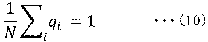
[Math. 11]
- When it is assumed that the time τi required for the hash calculation is constant regardless of the file, Formula (12) is a solution.
[Math. 12]
- As described above, since ki is proportional to the scan frequency for the file i, the optimization of the evaluation index E[τattack] according to the present embodiment is a method of "generating a random scan pattern in which scan is performed more frequently as access frequency of file is higher in consideration of time required for scan according to file size".
- A flow of the tampering detection processing according to the present embodiment will be described in detail with reference to
Fig. 6. Fig. 6 is a flowchart illustrating an example of a flow of tampering detection processing according to the first embodiment. First, theacquisition unit 14a of thetampering detection device 10 acquires information such as information of an access frequency and a file size of a monitoring target file from the monitoring target device 20 (step S101). At this time, theacquisition unit 14a may acquire the information from a device other than themonitoring target device 20. In addition, theacquisition unit 14a may acquire information directly input via the input unit 11. - Next, the determination unit 14c determines an optimum scan pattern on the basis of the information acquired from the
monitoring target device 20 such as access frequency (step S102). At this time, thecalculation unit 14b may perform calculation processing for information necessary for the determination unit 14c to determine the scan pattern. In addition, when there is a scan pattern created in advance, the determination unit 14c can also adopt this scan pattern. Further, when a plurality of scan patterns can be determined, the determination unit 14c can adopt one or a plurality of scan patterns from the scan patterns. - Subsequently, the
transmission unit 14d transmits the scan pattern to the monitoring target device 20 (step S103). At this time, thetransmission unit 14d may transmit the scan patterns in bulk (collectively) or may transmit the scan patterns one by one. In addition, thetransmission unit 14d may transmit a plurality of scan patterns. - Then, the
acquisition unit 14a acquires a digest of a file generated by thegeneration unit 24b of themonitoring target device 20 and transmitted by the transmission unit 24c (step S104). Finally, theverification unit 14e verifies whether the file has been tampered with on the basis of the digest of the file acquired by theacquisition unit 14a (step S105), and the tampering detection processing ends. Note that thetransmission unit 14d may transmit whether the file has been tampered with verified by theverification unit 14e to themonitoring target device 20 or another terminal. - The flow of the scan pattern determination processing according to the present embodiment will be described in detail with reference to
Fig. 7. Fig. 7 is a flowchart illustrating an example of a flow of scan pattern determination processing according to the first embodiment. - First, the
acquisition unit 14a of thetampering detection device 10 acquires an access log of a monitoring target file in themonitoring target device 20 for a certain period from the monitoring target device 20 (step S201), and acquires an access frequency for each monitoring target file from the access log (step S202). - At this time, the
acquisition unit 14a may acquire the access log from a device other than themonitoring target device 20. In addition, theacquisition unit 14a may acquire the access log directly input via the input unit 11. Note that in a certain period regarding the acquisition of the access log, themonitoring target device 20 may perform the scan processing by an arbitrary method or may not perform the scan processing. - Next, the
acquisition unit 14a of thetampering detection device 10 acquires the file size of the monitoring target file from the monitoring target device 20 (step S203). At this time, theacquisition unit 14a may acquire the file size from a device other than themonitoring target device 20. In addition, theacquisition unit 14a may acquire the file size directly input via the input unit 11. - Then, the
acquisition unit 14a calculates and acquires a time τi required for hash calculation for each file from the file size described above and the like (step S204). Note that theacquisition unit 14a uses above Formula (1) when calculating τi described above. In addition, theacquisition unit 14a may calculate and acquire an average time τav required for hash calculation of the file represented by Formula (2) described above. - Subsequently, the
acquisition unit 14a acquires a set time τall of one scan processing cycle (step S205). Here, τall is a numerical value given as a set value from the outside, but is not particularly limited. Theacquisition unit 14a may acquire τall from themonitoring target device 20 or another terminal, or may acquire τall directly input via the input unit 11. - Note that the order of the processing of steps S201 to S205 is exemplary, and the
acquisition unit 14a can also perform the processing in a different order. In addition, theacquisition unit 14a can omit part of the processing of steps S201 to S205. - Thereafter, the
calculation unit 14b calculates the number of times of scanning ki of one cycle that minimizes the evaluation index E[τattack] using acquired τi and τall (step S206). At this time, when it is desired to generate a scan pattern so as to scan all the files at least once in one cycle, thecalculation unit 14b sets the minimum value of ki for an arbitrary file to one (step S207). Finally, the determination unit 14c randomly determines a scan pattern that satisfies ki (step S208), and the processing ends. - First, in the tampering detection processing according to the present embodiment described above, the access frequency of the monitoring target file is acquired, the number of times of scanning in the scan pattern is calculated for each monitoring target file on the basis of the acquired access frequency, and the scan pattern is determined on the basis of the calculated number of times of scanning. Thus, in the present processing, it is possible to reduce the possibility that an authorized program executes an illicitly tampered file while suppressing use resources in a monitoring target device.
- Second, in the tampering detection processing according to the present embodiment described above, the file size of the monitoring target file and the scan pattern set time are further acquired, and the number of times of scanning is calculated on the basis of the access frequency, the file size, and the set time. Thus, in the present processing, it is possible to more efficiently reduce the possibility that an authorized program executes an illicitly tampered file while suppressing use resources in a monitoring target device.
- Third, in the tampering detection processing according to the present embodiment described above, the number of times of scanning that minimizes an average time from scanning of the monitoring target file to the latest access is calculated. Thus, in the present processing, it is possible to more effectively reduce the possibility that an authorized program executes an illicitly tampered file while suppressing use resources in a monitoring target device.
- Fourth, in the tampering detection processing according to the present embodiment described above, a scan pattern in which all the monitoring target files are included at least once is randomly determined on the basis of the number of times of scanning. Thus, in the present processing, it is possible to more comprehensively reduce the possibility that an authorized program executes an illicitly tampered file while suppressing use resources in a monitoring target device.
- Fifth, in the tampering detection processing according to the present embodiment described above, the access frequency is acquired from the monitoring target device that stores the monitoring target file, the scan pattern is transmitted to the monitoring target device, and whether or not the file has been tampered with is verified using the digest of the file generated on the basis of the scan pattern by the monitoring target device. Thus, in the present processing, in software tampering detection, it is possible to optimally and comprehensively monitor all the files, and it is possible to reduce the possibility that an authorized program executes an illicitly tampered file while suppressing use resources in the monitoring target device.
- Each component of each device that has been illustrated according to the embodiment described above is functionally conceptual and does not necessarily have to be physically configured as illustrated. In other words, a specific form of distribution and integration of individual devices is not limited to the illustrated form, and all or part of the configuration can be functionally or physically distributed and integrated in any unit according to various loads, usage conditions, and the like. Further, all or any part of each processing function performed in each device can be implemented by a CPU and a program to be analyzed and executed by the CPU or can be implemented as hardware by wired logic.
- In addition, among the individual processing described in the embodiment described above, all or part of the processing described as being automatically performed can be manually performed, or all or part of the processing described as being manually performed can be automatically performed by a known method. Additionally, the processing procedures, the control procedures, the specific names, and the information including various data and parameters illustrated in the specification and the drawings can be arbitrarily changed unless otherwise specified.
- In addition, it is also possible to create a program in which the processing executed by the
tampering detection device 10 described in the foregoing embodiment is described in a language which can be executed by a computer. In this case, the computer executes the program, and thus, the effects similar to those of the embodiment described above can be obtained. Further, the program may be recorded in a computer-readable recording medium, and the program recorded in the recording medium may be read and executed by the computer. Thereby, processing similar to the embodiment described above may be realized. -
Fig. 8 is a diagram illustrating a computer that executes a program. As illustrated inFig. 8 , acomputer 1000 includes, for example,memory 1010, aCPU 1020, a harddisk drive interface 1030, adisk drive interface 1040, aserial port interface 1050, avideo adapter 1060, and anetwork interface 1070. These units are connected by a bus 1080. - As exemplified in
Fig. 8 , thememory 1010 includes a read only memory (ROM) 1011 and aRAM 1012. TheROM 1011 stores, for example, a boot program such as a basic input output system (BIOS). The harddisk drive interface 1030 is connected to ahard disk drive 1090 as exemplified inFig. 8 . Thedisk drive interface 1040 is connected to adisk drive 1100 as exemplified inFig. 8 . For example, a removable storage medium such as a magnetic disk or an optical disk is inserted into thedisk drive 1100. As exemplified inFig. 8 , theserial port interface 1050 is connected to, for example, amouse 1110 and akeyboard 1120. As exemplified inFig. 8 , thevideo adapter 1060 is connected to, for example, adisplay 1130. - Here, as exemplified in
Fig. 8 , thehard disk drive 1090 stores, for example, anOS 1091, anapplication program 1092, aprogram module 1093, andprogram data 1094. In other words, the above program is stored, for example, in thehard disk drive 1090 as a program module in which a command to be executed by thecomputer 1000 is described. - In addition, various data described in the embodiment described above is stored as program data in, for example, the
memory 1010 and thehard disk drive 1090. Then, theCPU 1020 reads out theprogram module 1093 and theprogram data 1094 stored in thememory 1010 and thehard disk drive 1090 to theRAM 1012 as necessary and executes various processing procedures. - Note that the
program module 1093 and theprogram data 1094 related to the program are not limited to being stored in thehard disk drive 1090 and may be stored in, for example, a removable storage medium and may be read by theCPU 1020 via a disk drive, or the like. Alternatively, theprogram module 1093 and theprogram data 1094 related to the program may be stored in another computer connected via a network (such as a local area network (LAN) or a wide area network (WAN)) and may be read by theCPU 1020 via thenetwork interface 1070. - The embodiment described above and modifications thereof are included in the inventions recited in the claims and the equivalent scope thereof, similarly to being included in the technique disclosed in the present application.
-
- 10
- Tampering detection device
- 11
- Input unit
- 12
- Output unit
- 13
- Communication unit
- 14
- Control unit
- 14a
- Acquisition unit
- 14b
- Calculation unit
- 14c
- Determination unit
- 14d
- Transmission unit
- 14e
- Verification unit
- 15
- Storage unit
- 15a
- Monitoring target device information storage unit
- 15b
- File information storage unit
- 15c
- File digest storage unit
- 20
- Monitoring target device
- 21
- Input unit
- 22
- Output unit
- 23
- Communication unit
- 24
- Control unit
- 24a
- Acquisition unit
- 24b
- Generation unit
- 24c
- Transmission unit
- 25
- Storage unit
- 25a
- Monitoring target file storage unit
- 100
- Tampering detection system
Claims (7)
- A tampering detection device comprising:an acquisition unit that acquires an access frequency of a monitoring target file;a calculation unit that calculates a number of times of scanning in a scan pattern for each monitoring target file on a basis of the access frequency acquired by the acquisition unit; anda determination unit that determines the scan pattern on a basis of the number of times of scanning calculated by the calculation unit.
- The tampering detection device according to claim 1, whereinthe acquisition unit further acquires a file size of the monitoring target file and a set time of the scan pattern, andthe calculation unit calculates the number of times of scanning on a basis of the access frequency, the file size, and the set time.
- The tampering detection device according to claim 1 or 2, wherein
the calculation unit calculates the number of times of scanning that minimizes an average time from scanning of the monitoring target file to a latest access. - The tampering detection device according to any one of claims 1 to 3, wherein
the determination unit randomly determines a scan pattern in which all the monitoring target files are included at least once on a basis of the number of times of scanning. - The tampering detection device according to any one of claims 1 to 4, whereinthe acquisition unit acquires the access frequency from a monitoring target device that stores the monitoring target file, andthe tampering detection device further comprises:a transmission unit that transmits the scan pattern to the monitoring target device; anda verification unit that verifies whether or not the file has been tampered by using a digest of a file generated on a basis of the scan pattern by the monitoring target device.
- A tampering detection method executed by a tampering detection device, the method comprising:an acquisition process of acquiring an access frequency of a monitoring target file;a calculation process of calculating a number of times of scanning in a scan pattern for each monitoring target file on a basis of the access frequency acquired by the acquisition process; anda determination process of determining the scan pattern on a basis of the number of times of scanning calculated by the calculation process.
- A tampering detection program causing a computer to execute:an acquisition step of acquiring an access frequency of a monitoring target file;a calculation step of calculating a number of times of scanning in a scan pattern for each monitoring target file on a basis of the access frequency acquired by the acquisition step; anda determination step of determining the scan pattern on a basis of the number of times of scanning calculated by the calculation step.
Applications Claiming Priority (1)
| Application Number | Priority Date | Filing Date | Title |
|---|---|---|---|
| PCT/JP2021/000909 WO2022153410A1 (en) | 2021-01-13 | 2021-01-13 | Falsification detection device, falsification detection method, and falsification detection program |
Publications (3)
| Publication Number | Publication Date |
|---|---|
| EP4261719A1 true EP4261719A1 (en) | 2023-10-18 |
| EP4261719A4 EP4261719A4 (en) | 2024-08-28 |
| EP4261719B1 EP4261719B1 (en) | 2026-03-04 |
Family
ID=82448018
Family Applications (1)
| Application Number | Title | Priority Date | Filing Date |
|---|---|---|---|
| EP21919304.2A Active EP4261719B1 (en) | 2021-01-13 | 2021-01-13 | Falsification detection device, falsification detection method, and falsification detection program |
Country Status (6)
| Country | Link |
|---|---|
| US (1) | US12386961B2 (en) |
| EP (1) | EP4261719B1 (en) |
| JP (1) | JP7509242B2 (en) |
| CN (1) | CN116783595A (en) |
| AU (1) | AU2021419833B2 (en) |
| WO (1) | WO2022153410A1 (en) |
Family Cites Families (11)
| Publication number | Priority date | Publication date | Assignee | Title |
|---|---|---|---|---|
| JP2004013607A (en) * | 2002-06-07 | 2004-01-15 | Hitachi Ltd | File monitoring device |
| US7475427B2 (en) * | 2003-12-12 | 2009-01-06 | International Business Machines Corporation | Apparatus, methods and computer programs for identifying or managing vulnerabilities within a data processing network |
| JP2010211453A (en) | 2009-03-10 | 2010-09-24 | Yamatake Corp | File tampering check method and device |
| US8392379B2 (en) * | 2009-03-17 | 2013-03-05 | Sophos Plc | Method and system for preemptive scanning of computer files |
| US10733183B2 (en) * | 2015-12-06 | 2020-08-04 | Innominds Inc. | Method for searching for reliable, significant and relevant patterns |
| JP6713954B2 (en) | 2017-06-20 | 2020-06-24 | 日本電信電話株式会社 | File management device and file management method |
| JP6787841B2 (en) | 2017-06-28 | 2020-11-18 | 日本電信電話株式会社 | Access control device, access control method and access control program |
| JP6700337B2 (en) * | 2018-05-30 | 2020-05-27 | 日本電信電話株式会社 | Protection device and protection method |
| US11593480B2 (en) * | 2018-07-24 | 2023-02-28 | EMC IP Holding Company LLC | Predictive scheduled anti-virus scanning |
| CN109583204B (en) * | 2018-11-20 | 2021-03-02 | 国网陕西省电力公司 | Method for monitoring static object tampering in mixed environment |
| CN116685974A (en) * | 2021-01-13 | 2023-09-01 | 日本电信电话株式会社 | Tamper detection device, tamper detection method and tamper detection program |
-
2021
- 2021-01-13 AU AU2021419833A patent/AU2021419833B2/en active Active
- 2021-01-13 US US18/272,094 patent/US12386961B2/en active Active
- 2021-01-13 WO PCT/JP2021/000909 patent/WO2022153410A1/en not_active Ceased
- 2021-01-13 EP EP21919304.2A patent/EP4261719B1/en active Active
- 2021-01-13 JP JP2022574924A patent/JP7509242B2/en active Active
- 2021-01-13 CN CN202180090273.8A patent/CN116783595A/en active Pending
Also Published As
| Publication number | Publication date |
|---|---|
| EP4261719B1 (en) | 2026-03-04 |
| AU2021419833B2 (en) | 2024-04-11 |
| US20240303332A1 (en) | 2024-09-12 |
| AU2021419833A1 (en) | 2023-07-13 |
| AU2021419833A9 (en) | 2024-08-01 |
| JP7509242B2 (en) | 2024-07-02 |
| JPWO2022153410A1 (en) | 2022-07-21 |
| CN116783595A (en) | 2023-09-19 |
| US12386961B2 (en) | 2025-08-12 |
| EP4261719A4 (en) | 2024-08-28 |
| WO2022153410A1 (en) | 2022-07-21 |
Similar Documents
| Publication | Publication Date | Title |
|---|---|---|
| EP4261720B1 (en) | Falsification detecting device, falsification detecting method, and falsification detecting program | |
| CN111967016B (en) | Dynamic monitoring method of baseboard management controller and baseboard management controller | |
| US11928208B2 (en) | Calculation device, calculation method, and calculation program | |
| JP2015108898A (en) | Abnormality detection system and abnormality detection method | |
| JP7211429B2 (en) | Information processing device, control method, and program | |
| EP4261719B1 (en) | Falsification detection device, falsification detection method, and falsification detection program | |
| CN110443035B (en) | Method and apparatus for calibrating a system for identifying intrusion attempts | |
| CN108197498A (en) | Obtain the method and device of data | |
| CN113158177A (en) | Dynamic measurement method, device, equipment and storage medium | |
| CN119766538B (en) | A server access control method and system based on network security protection | |
| CN113806737A (en) | Malicious process risk level evaluation method, terminal device and storage medium | |
| JP6204318B2 (en) | Similarity Evaluation Device, Similarity Evaluation System, Similarity Evaluation Device Method, and Similarity Evaluation Program | |
| JP2024041711A (en) | Information processing device, control method and program for information processing device | |
| EP4333377A1 (en) | Analysis device, analysis method, and analysis program | |
| WO2022102110A1 (en) | Falsification detection device, falsification detection method, and falsification detection program | |
| JP2017102566A (en) | Unauthorized file detection device, unauthorized file detection method and unauthorized file detection program | |
| EP4009210A1 (en) | Verification device, verification system, verification method, and verification program | |
| CN114491551B (en) | Multi-metric system trustworthy verification method, device, computer equipment and storage medium | |
| CN113030558A (en) | Method, device and equipment for identifying data abnormity and readable storage medium | |
| CN117043770A (en) | Communication service sensors, analysis methods and analysis procedures | |
| JP7287093B2 (en) | Learning program, learning method and learning device | |
| CN115080578B (en) | Web page evidence implementation method and device based on blockchain, and computer storage medium | |
| JP2018067126A (en) | Similarity evaluating device, similarity evaluating system, similarity evaluating method, and similarity evaluating program | |
| CN119862564A (en) | Startup security detection method, device, medium and program product for embedded system | |
| JP2019008470A (en) | Management device, simulation system, and simulation method |
Legal Events
| Date | Code | Title | Description |
|---|---|---|---|
| STAA | Information on the status of an ep patent application or granted ep patent |
Free format text: STATUS: THE INTERNATIONAL PUBLICATION HAS BEEN MADE |
|
| PUAI | Public reference made under article 153(3) epc to a published international application that has entered the european phase |
Free format text: ORIGINAL CODE: 0009012 |
|
| STAA | Information on the status of an ep patent application or granted ep patent |
Free format text: STATUS: REQUEST FOR EXAMINATION WAS MADE |
|
| 17P | Request for examination filed |
Effective date: 20230712 |
|
| AK | Designated contracting states |
Kind code of ref document: A1 Designated state(s): AL AT BE BG CH CY CZ DE DK EE ES FI FR GB GR HR HU IE IS IT LI LT LU LV MC MK MT NL NO PL PT RO RS SE SI SK SM TR |
|
| DAV | Request for validation of the european patent (deleted) | ||
| DAX | Request for extension of the european patent (deleted) | ||
| REG | Reference to a national code |
Ref country code: DE Ref legal event code: R079 Free format text: PREVIOUS MAIN CLASS: G06F0021550000 Ipc: G06F0021570000 Ref country code: DE Ref legal event code: R079 Ref document number: 602021049513 Country of ref document: DE Free format text: PREVIOUS MAIN CLASS: G06F0021550000 Ipc: G06F0021570000 |
|
| A4 | Supplementary search report drawn up and despatched |
Effective date: 20240729 |
|
| RIC1 | Information provided on ipc code assigned before grant |
Ipc: G06F 21/64 20130101ALI20240723BHEP Ipc: G06F 21/57 20130101AFI20240723BHEP |
|
| STAA | Information on the status of an ep patent application or granted ep patent |
Free format text: STATUS: EXAMINATION IS IN PROGRESS |
|
| 17Q | First examination report despatched |
Effective date: 20250507 |
|
| GRAP | Despatch of communication of intention to grant a patent |
Free format text: ORIGINAL CODE: EPIDOSNIGR1 |
|
| STAA | Information on the status of an ep patent application or granted ep patent |
Free format text: STATUS: GRANT OF PATENT IS INTENDED |
|
| RAP3 | Party data changed (applicant data changed or rights of an application transferred) |
Owner name: NTT, INC. |
|
| RIC1 | Information provided on ipc code assigned before grant |
Ipc: G06F 21/57 20130101AFI20250904BHEP |
|
| INTG | Intention to grant announced |
Effective date: 20250926 |
|
| GRAS | Grant fee paid |
Free format text: ORIGINAL CODE: EPIDOSNIGR3 |
|
| GRAA | (expected) grant |
Free format text: ORIGINAL CODE: 0009210 |
|
| STAA | Information on the status of an ep patent application or granted ep patent |
Free format text: STATUS: THE PATENT HAS BEEN GRANTED |
|
| AK | Designated contracting states |
Kind code of ref document: B1 Designated state(s): AL AT BE BG CH CY CZ DE DK EE ES FI FR GB GR HR HU IE IS IT LI LT LU LV MC MK MT NL NO PL PT RO RS SE SI SK SM TR |
|
| REG | Reference to a national code |
Ref country code: CH Ref legal event code: F10 Free format text: ST27 STATUS EVENT CODE: U-0-0-F10-F00 (AS PROVIDED BY THE NATIONAL OFFICE) Effective date: 20260304 Ref country code: GB Ref legal event code: FG4D |
|
| REG | Reference to a national code |
Ref country code: IE Ref legal event code: FG4D |
|
| REG | Reference to a national code |
Ref country code: DE Ref legal event code: R096 Ref document number: 602021049513 Country of ref document: DE |
|
| PG25 | Lapsed in a contracting state [announced via postgrant information from national office to epo] |
Ref country code: RS Free format text: LAPSE BECAUSE OF FAILURE TO SUBMIT A TRANSLATION OF THE DESCRIPTION OR TO PAY THE FEE WITHIN THE PRESCRIBED TIME-LIMIT Effective date: 20260604 |
|
| PG25 | Lapsed in a contracting state [announced via postgrant information from national office to epo] |
Ref country code: ES Free format text: LAPSE BECAUSE OF FAILURE TO SUBMIT A TRANSLATION OF THE DESCRIPTION OR TO PAY THE FEE WITHIN THE PRESCRIBED TIME-LIMIT Effective date: 20260304 |
|
| REG | Reference to a national code |
Ref country code: NL Ref legal event code: MP Effective date: 20260304 |
|
| PG25 | Lapsed in a contracting state [announced via postgrant information from national office to epo] |
Ref country code: PL Free format text: LAPSE BECAUSE OF FAILURE TO SUBMIT A TRANSLATION OF THE DESCRIPTION OR TO PAY THE FEE WITHIN THE PRESCRIBED TIME-LIMIT Effective date: 20260304 |
|
| PG25 | Lapsed in a contracting state [announced via postgrant information from national office to epo] |
Ref country code: GR Free format text: LAPSE BECAUSE OF FAILURE TO SUBMIT A TRANSLATION OF THE DESCRIPTION OR TO PAY THE FEE WITHIN THE PRESCRIBED TIME-LIMIT Effective date: 20260605 |
|
| REG | Reference to a national code |
Ref country code: LT Ref legal event code: MG9D |
|
| PG25 | Lapsed in a contracting state [announced via postgrant information from national office to epo] |
Ref country code: LT Free format text: LAPSE BECAUSE OF FAILURE TO SUBMIT A TRANSLATION OF THE DESCRIPTION OR TO PAY THE FEE WITHIN THE PRESCRIBED TIME-LIMIT Effective date: 20260304 |
|
| PG25 | Lapsed in a contracting state [announced via postgrant information from national office to epo] |
Ref country code: NO Free format text: LAPSE BECAUSE OF FAILURE TO SUBMIT A TRANSLATION OF THE DESCRIPTION OR TO PAY THE FEE WITHIN THE PRESCRIBED TIME-LIMIT Effective date: 20260604 |
|
| PG25 | Lapsed in a contracting state [announced via postgrant information from national office to epo] |
Ref country code: FI Free format text: LAPSE BECAUSE OF FAILURE TO SUBMIT A TRANSLATION OF THE DESCRIPTION OR TO PAY THE FEE WITHIN THE PRESCRIBED TIME-LIMIT Effective date: 20260304 Ref country code: SE Free format text: LAPSE BECAUSE OF FAILURE TO SUBMIT A TRANSLATION OF THE DESCRIPTION OR TO PAY THE FEE WITHIN THE PRESCRIBED TIME-LIMIT Effective date: 20260304 |
|
| PG25 | Lapsed in a contracting state [announced via postgrant information from national office to epo] |
Ref country code: HR Free format text: LAPSE BECAUSE OF FAILURE TO SUBMIT A TRANSLATION OF THE DESCRIPTION OR TO PAY THE FEE WITHIN THE PRESCRIBED TIME-LIMIT Effective date: 20260304 |
|
| PG25 | Lapsed in a contracting state [announced via postgrant information from national office to epo] |
Ref country code: LV Free format text: LAPSE BECAUSE OF FAILURE TO SUBMIT A TRANSLATION OF THE DESCRIPTION OR TO PAY THE FEE WITHIN THE PRESCRIBED TIME-LIMIT Effective date: 20260304 |
|
| PG25 | Lapsed in a contracting state [announced via postgrant information from national office to epo] |
Ref country code: BG Free format text: LAPSE BECAUSE OF FAILURE TO SUBMIT A TRANSLATION OF THE DESCRIPTION OR TO PAY THE FEE WITHIN THE PRESCRIBED TIME-LIMIT Effective date: 20260304 |