EP4261431A1 - Slotted torque plate barrel - Google Patents
Slotted torque plate barrel Download PDFInfo
- Publication number
- EP4261431A1 EP4261431A1 EP23166740.3A EP23166740A EP4261431A1 EP 4261431 A1 EP4261431 A1 EP 4261431A1 EP 23166740 A EP23166740 A EP 23166740A EP 4261431 A1 EP4261431 A1 EP 4261431A1
- Authority
- EP
- European Patent Office
- Prior art keywords
- torque
- barrel
- elongated hole
- width
- disposed
- Prior art date
- Legal status (The legal status is an assumption and is not a legal conclusion. Google has not performed a legal analysis and makes no representation as to the accuracy of the status listed.)
- Granted
Links
Images




Classifications
-
- F—MECHANICAL ENGINEERING; LIGHTING; HEATING; WEAPONS; BLASTING
- F16—ENGINEERING ELEMENTS AND UNITS; GENERAL MEASURES FOR PRODUCING AND MAINTAINING EFFECTIVE FUNCTIONING OF MACHINES OR INSTALLATIONS; THERMAL INSULATION IN GENERAL
- F16D—COUPLINGS FOR TRANSMITTING ROTATION; CLUTCHES; BRAKES
- F16D65/00—Parts or details
- F16D65/02—Braking members; Mounting thereof
- F16D65/04—Bands, shoes or pads; Pivots or supporting members therefor
- F16D65/092—Bands, shoes or pads; Pivots or supporting members therefor for axially-engaging brakes, e.g. disc brakes
- F16D65/095—Pivots or supporting members therefor
-
- B—PERFORMING OPERATIONS; TRANSPORTING
- B64—AIRCRAFT; AVIATION; COSMONAUTICS
- B64C—AEROPLANES; HELICOPTERS
- B64C25/00—Alighting gear
- B64C25/32—Alighting gear characterised by elements which contact the ground or similar surface
- B64C25/42—Arrangement or adaptation of brakes
-
- B—PERFORMING OPERATIONS; TRANSPORTING
- B64—AIRCRAFT; AVIATION; COSMONAUTICS
- B64C—AEROPLANES; HELICOPTERS
- B64C25/00—Alighting gear
- B64C25/32—Alighting gear characterised by elements which contact the ground or similar surface
- B64C25/42—Arrangement or adaptation of brakes
- B64C25/44—Actuating mechanisms
-
- F—MECHANICAL ENGINEERING; LIGHTING; HEATING; WEAPONS; BLASTING
- F16—ENGINEERING ELEMENTS AND UNITS; GENERAL MEASURES FOR PRODUCING AND MAINTAINING EFFECTIVE FUNCTIONING OF MACHINES OR INSTALLATIONS; THERMAL INSULATION IN GENERAL
- F16D—COUPLINGS FOR TRANSMITTING ROTATION; CLUTCHES; BRAKES
- F16D55/00—Brakes with substantially-radial braking surfaces pressed together in axial direction, e.g. disc brakes
- F16D55/24—Brakes with substantially-radial braking surfaces pressed together in axial direction, e.g. disc brakes with a plurality of axially-movable discs, lamellae, or pads, pressed from one side towards an axially-located member
- F16D55/26—Brakes with substantially-radial braking surfaces pressed together in axial direction, e.g. disc brakes with a plurality of axially-movable discs, lamellae, or pads, pressed from one side towards an axially-located member without self-tightening action
- F16D55/36—Brakes with a plurality of rotating discs all lying side by side
-
- F—MECHANICAL ENGINEERING; LIGHTING; HEATING; WEAPONS; BLASTING
- F16—ENGINEERING ELEMENTS AND UNITS; GENERAL MEASURES FOR PRODUCING AND MAINTAINING EFFECTIVE FUNCTIONING OF MACHINES OR INSTALLATIONS; THERMAL INSULATION IN GENERAL
- F16D—COUPLINGS FOR TRANSMITTING ROTATION; CLUTCHES; BRAKES
- F16D65/00—Parts or details
- F16D65/14—Actuating mechanisms for brakes; Means for initiating operation at a predetermined position
- F16D65/16—Actuating mechanisms for brakes; Means for initiating operation at a predetermined position arranged in or on the brake
- F16D65/18—Actuating mechanisms for brakes; Means for initiating operation at a predetermined position arranged in or on the brake adapted for drawing members together, e.g. for disc brakes
- F16D65/186—Actuating mechanisms for brakes; Means for initiating operation at a predetermined position arranged in or on the brake adapted for drawing members together, e.g. for disc brakes with full-face force-applying member, e.g. annular
-
- F—MECHANICAL ENGINEERING; LIGHTING; HEATING; WEAPONS; BLASTING
- F16—ENGINEERING ELEMENTS AND UNITS; GENERAL MEASURES FOR PRODUCING AND MAINTAINING EFFECTIVE FUNCTIONING OF MACHINES OR INSTALLATIONS; THERMAL INSULATION IN GENERAL
- F16D—COUPLINGS FOR TRANSMITTING ROTATION; CLUTCHES; BRAKES
- F16D65/00—Parts or details
- F16D65/78—Features relating to cooling
- F16D65/84—Features relating to cooling for disc brakes
- F16D65/847—Features relating to cooling for disc brakes with open cooling system, e.g. cooled by air
-
- F—MECHANICAL ENGINEERING; LIGHTING; HEATING; WEAPONS; BLASTING
- F16—ENGINEERING ELEMENTS AND UNITS; GENERAL MEASURES FOR PRODUCING AND MAINTAINING EFFECTIVE FUNCTIONING OF MACHINES OR INSTALLATIONS; THERMAL INSULATION IN GENERAL
- F16D—COUPLINGS FOR TRANSMITTING ROTATION; CLUTCHES; BRAKES
- F16D55/00—Brakes with substantially-radial braking surfaces pressed together in axial direction, e.g. disc brakes
- F16D2055/0004—Parts or details of disc brakes
- F16D2055/0008—Brake supports
-
- F—MECHANICAL ENGINEERING; LIGHTING; HEATING; WEAPONS; BLASTING
- F16—ENGINEERING ELEMENTS AND UNITS; GENERAL MEASURES FOR PRODUCING AND MAINTAINING EFFECTIVE FUNCTIONING OF MACHINES OR INSTALLATIONS; THERMAL INSULATION IN GENERAL
- F16D—COUPLINGS FOR TRANSMITTING ROTATION; CLUTCHES; BRAKES
- F16D55/00—Brakes with substantially-radial braking surfaces pressed together in axial direction, e.g. disc brakes
- F16D2055/0004—Parts or details of disc brakes
- F16D2055/0058—Fully lined, i.e. braking surface extending over the entire disc circumference
-
- F—MECHANICAL ENGINEERING; LIGHTING; HEATING; WEAPONS; BLASTING
- F16—ENGINEERING ELEMENTS AND UNITS; GENERAL MEASURES FOR PRODUCING AND MAINTAINING EFFECTIVE FUNCTIONING OF MACHINES OR INSTALLATIONS; THERMAL INSULATION IN GENERAL
- F16D—COUPLINGS FOR TRANSMITTING ROTATION; CLUTCHES; BRAKES
- F16D65/00—Parts or details
- F16D65/02—Braking members; Mounting thereof
- F16D2065/13—Parts or details of discs or drums
- F16D2065/134—Connection
- F16D2065/1356—Connection interlocking
- F16D2065/1364—Connection interlocking with relative movement axially
-
- F—MECHANICAL ENGINEERING; LIGHTING; HEATING; WEAPONS; BLASTING
- F16—ENGINEERING ELEMENTS AND UNITS; GENERAL MEASURES FOR PRODUCING AND MAINTAINING EFFECTIVE FUNCTIONING OF MACHINES OR INSTALLATIONS; THERMAL INSULATION IN GENERAL
- F16D—COUPLINGS FOR TRANSMITTING ROTATION; CLUTCHES; BRAKES
- F16D2250/00—Manufacturing; Assembly
Definitions
- the present disclosure generally relates to aircraft wheel and brake systems and, more particularly, to torque plates and barrels for brake assemblies.
- Aircraft typically utilize brake systems on wheels to slow or stop the aircraft during landings, taxiing, and rejected takeoffs.
- the brake systems generally employ a brake stack comprising a series of friction disks that may be forced into sliding contact with one another during brake actuation to slow or stop the aircraft.
- a torque plate and barrel is employed to support the series of friction disks.
- the torque barrel may include a torque barrel having a cylindrical structure including an inner surface, an outer surface, a first opening at a first end, and a second opening at an opposing second end; and a longitudinal hole disposed through the outer surface of the barrel between a first spline of the plurality of splines and a second spline of the plurality of splines.
- the longitudinal hole has a first end having a tear drop shape.
- the first end has a length and a width, the length to width ratio being about 1.5:1.
- the longitudinal hole has a width in a circumferential direction and a length in an axial direction and the width of the longitudinal hole at a first end is greater than the width at the second end.
- the one or more longitudinal holes have a first end, an opposing second end, and a center portion, the center portion having a first width and the first end having a second width that is greater than the first width.
- the torque barrel may further include a second longitudinal hole disposed between the longitudinal hole and the first end of the barrel.
- the second longitudinal hole is axially in line with and aft of the longitudinal hole.
- the longitudinal hole has a first length and the second longitudinal hole has a second length that is less than the first length.
- the torque barrel may further include a plurality of longitudinal holes disposed through the outer surface of the torque barrel, the plurality of longitudinal holes being disposed symmetrically.
- the torque barrel may further include a plurality of splines disposed around a circumference of the barrel and extending from the first end to the second end along the outer surface of the barrel.
- the torque barrel may further include a torque plate coupled to the second end of the barrel, the torque plate including a plurality of back legs, each back leg of the plurality of back legs having a hole disposed therein.
- the brake assembly may include a torque barrel having an outer surface and an axial length; an elongated hole disposed in the outer surface along the axial length, the elongated hole having a rounded first end and an opposing rounded second end; a heat sink disposed around the torque tube; and a plurality of stator disks mounted to the torque barrel.
- the rounded first end has a length and a width, the length being greater than the width.
- the elongated hole has a center portion extending between the first end and the second end, the center portion having a second width that is less than the width.
- the elongated hole is a first elongated hole
- the brake assembly may further include a second elongated hole disposed in the outer surface of the torque tube, the second elongated hole being disposed along the axial length of the torque tube and circumferentially adjacent the first elongated hole.
- the second elongated hole is longer than the first elongated hole.
- the brake assembly may further include a spline disposed along the outer surface of the torque tube adjacent the elongated hole.
- the elongated hole is a first elongated hole and the brake assembly further include a second elongated hole disposed axially in line with the first elongated hole.
- the elongated hole is a first elongated hole and the brake assembly may further include a second elongated hole disposed in the outer surface of the torque tube, the second elongated hole having a first end and a second end, the first end of the second elongated being axially offset from the first elongated hole.
- a method of forming a torque barrel is disclosed herein.
- the method may include forming a barrel having an outer surface having a first end and an opposing second end; and forming an elongated hole in the outer surface of the barrel, the elongated hole having a first end, an opposing second end, and a center portion, the elongated hole extending between the first end and the second end.
- references to "a,” “an” or “the” may include one or more than one and that reference to an item in the singular may also include the item in the plural. Further, all ranges may include upper and lower values and all ranges and ratio limits disclosed herein may be combined.
- an aircraft 10 is illustrated.
- the aircraft 10 includes landing gear, which may include a left main landing gear 12, a right main landing gear 14 and a nose landing gear 16.
- the landing gear support the aircraft 10 when it is not flying, allowing the aircraft 10 to taxi, take off and land without damage. While the disclosure refers to the three landing gear configurations just referred, the disclosure nevertheless contemplates any number of landing gear configurations.
- FIG. 1B there is schematically depicted a brake mechanism 100 that may be used by the aircraft 10 of Figure 1A or any other appropriate aircraft.
- the brake mechanism 100 is mounted on an axle 102 for use with a wheel 104 disposed on and configured to rotate about the axle 102 via one or more bearing assemblies 103.
- the wheel 104 includes a hub 106, a wheel well 108 concentric about the hub 106 and a web portion 110 interconnecting the hub 106 and the wheel well 108.
- a central axis 112 extends through the axle 102 and defines a center of rotation of the wheel 104.
- a torque plate barrel 114 (sometimes referred to as a torque tube or barrel or a torque plate or back leg) is aligned concentrically with the hub 106, and the wheel 104 is rotatable relative to the torque plate barrel 114.
- the brake mechanism 100 includes a piston assembly 116, a pressure plate 118 disposed adjacent the piston assembly 116, an end plate 120 positioned a distal location from the piston assembly 116, and a plurality of rotor disks 122 interleaved with a plurality of stator disks 124 positioned intermediate the pressure plate 118 and the end plate 120.
- the pressure plate 118, the plurality of rotor disks 122, the plurality of stator disks 124 and the end plate 120 together form a brake heat sink or brake stack 126.
- the pressure plate 118, the end plate 120 and the plurality of stator disks 124 are mounted to the torque plate barrel 114 and remain rotationally stationary relative to the axle 102.
- the torque plate barrel 114 may include an annular barrel or torque tube 128 and an annular plate or back leg 130.
- the back leg 130 is disposed at an end distal from the piston assembly 116 and may be made monolithic with the torque tube 128, as illustrated in Figure 1B , or may be made as a separate annular piece and suitably connected to the torque tube 128.
- the torque tube 128 has a plurality of circumferentially spaced and axially extending splines 132 disposed on an outer surface of the torque tube 128.
- the plurality of stator disks 124 and the pressure plate 118 include notches or stator slots 134 on an inner periphery of the disks and the plate for engagement with the splines 132, such that each disk and the plate are axially slidable with respect to the torque tube 128.
- the end plate 120 is suitably connected to the back leg 130 of the torque plate barrel 114 and is held non-rotatable, together with the plurality of stator disks 124 and the pressure plate 118, during a braking action.
- An actuating mechanism for the brake mechanism 100 includes a plurality of piston assemblies, including the piston assembly 116, circumferentially spaced around an annular piston housing 156 (only one piston assembly is illustrated in Figure 1B ).
- the plurality of piston assemblies affect a braking action by urging the pressure plate 118 and the plurality of stator disks 124 into frictional engagement with the plurality of rotor disks 122 and against the end plate 120.
- Fluid or hydraulic pressure, mechanical springs or electric actuators, among other mechanisms, may be used to actuate the plurality of piston assemblies.
- the plurality of rotor disks 122 and the plurality of stator disks 124 are fabricated from various materials, such as ceramic matrix composites, that enable the brake disks to withstand and dissipate the heat generated during and following a braking action.
- the torque plate barrel 114 is secured to a stationary portion of the landing gear such as the axle 102, preventing the torque plate barrel 114 and the plurality of stator disks 124 from rotating during braking of the aircraft.
- the torque tube 128 portion of the torque plate barrel 114 may be attached to the annular piston housing 156 via an annular mounting surface 158, wherein bolt fasteners 160 secure the torque plate barrel 114 to the annular piston housing 156.
- a spacer member or pedestal 162 is positioned between an inner diameter surface 164 of the torque tube 128 and an outer diameter surface 166 of the axle 102.
- the pedestal 162 includes a radially inner surface or foot 168 for engaging the axle 102, a web portion 170 radially outward of the foot 168 and a head portion 172 for engaging the inner diameter surface 164 of the torque tube 128.
- the pedestal 162 augments support of the torque plate barrel 114 within the brake mechanism 100 generally and, more particularly, against the axle 102.
- the pedestal 162 may be made monolithic with the torque tube 128 portion of the torque plate barrel 114.
- a heat shield 140 is secured directly or indirectly to the wheel 104 between a radially inward surface of the wheel well 108 and the plurality of torque bars 138. As illustrated in Figure 1B , the heat shield 140 is concentric with the wheel well 108 and may have a plurality of heat shield sections 142 disposed between respective, adjacent pairs of the plurality of torque bars 138.
- the heat shield 140 is spaced from the radially inward surface of the wheel well 108 and secured in place by heat shield tabs 190, such that the heat shield 140, or heat shield sections 142, is disposed generally parallel to the axis of rotation or central axis 112 of the wheel 104 and intermediate the plurality of torque bars 138 and the radially inward surface of the wheel well 108.
- the heat shield 140, or heat shield sections 142 may be further secured in place by heat shield carriers 144.
- the plurality of torque bars 138 is attached at axially inboard ends to the wheel 104 by torque bar bolts 146.
- the torque bar bolts 146 extend through respective holes in a flange 150 provided on the wheel 104 as shown, which flange 150 for purposes of the present description is intended to be considered as part of the wheel well 108.
- Each of the plurality of torque bars 138 may include a pin 152 or similar member at its axially outboard end (i.e., the end opposite the torque bar bolts 146) that is received within a hole 154 disposed proximate the web portion 110 of the wheel 104.
- the heat shield 140, or heat shield sections 142 is positioned adjacent a radially inward surface of the wheel well 108 and secured in place by the heat shield tabs 190.
- Each brake assembly including the torque plate barrel 114, is designed for a specific application and modes of operation.
- the size (e.g., length, diameter, thickness, etc.) and material of the torque plate barrel 114 may be modified to suit a particular application or improve a mode of operation. Different modes of operation that are considered include whirl, squeal, and disc squeal, just to name a few. Additional design considerations include dynamic stability, such as torsional compliance, axial compliance, and structural asymmetry, and cooling of the brake assembly, including the torque plate barrel 114.
- the torque plate barrel 200 may be an example of the torque plate barrel 114 described above.
- the torque plate barrel 200 includes a torque plate 202 and a torque barrel 204.
- the torque barrel 204 has a cylindrical, or tubular, structure having an opening at a first end 204a with an opening at an opposing second end 204b.
- the second end 204b of the torque barrel 204 is coupled to the torque plate 202.
- the torque plate barrel 200, the torque plate 202 and the torque barrel 204 may be formed as single unit.
- the torque plate barrel 200 may be formed from separate pieces where the torque barrel 204 and the torque plate 202 are coupled through other means such as welding, riveting, etc.
- FIG. 2A depicts a perspective view of the torque plate barrel 200 from the first end 204a of the torque barrel 204.
- FIG. 2B depicts an enlarged perspective view of the torque barrel 204 from the first end 204a of the torque barrel 204.
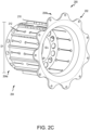
- FIG. 2C depicts a perspective view of the torque plate barrel 200 from the second end 204b of the torque barrel 204.
- the torque plate 202 includes back legs 206 that are circumferentially disposed around the outer edge of the torque plate 202.
- Each back leg 206 has a hole 208 disposed therein for mounting the torque plate barrel 200, specifically the torque plate 202, to a brake assembly.
- Each back leg 206 may be uniformly spaced around the circumference of the torque plate 202 to provide uniform support when mounting to the brake assembly.
- the torque barrel 204 extends from the torque plate 202 at the second end 204b.
- the torque barrel has a first length L1 that extends axially from the first end 204a to the second end 204b of the torque barrel 204. Additionally, the torque barrel 204 has a diameter D1 and a thickness t1.
- One or more splines 210 are circumferentially disposed around the exterior of the torque barrel 204.
- the one or more splines 210 may be uniformly spaced around the circumference of the torque barrel 204.
- each spline 210 may have a length that is equal to the length L1 of the torque barrel 204. In the depicted embodiment, each spline 210 has a length that is less than the length L1 of the torque barrel 204.
- One or more engineered slots 212 are formed in, and extending through, the surface the torque barrel 204 in strategic locations to achieve dynamic stability and convective cooling of the heatsink.
- the slots 212 may alternatively be referred to as elongated holes or longitudinal holes.
- the slots 212 extend through the thickness t1 of the torque barrel 204.
- the shape, size, space, and location can be tailored to shift a particular problematic frequency to a more benign frequency and/or achieve tailored convective cooling or thermal balance.
- the slots 212 allow increased air flow around and through the torque barrel 204 which accelerates the cooling of the heat sink disposed around the outer diameter of the torque barrel 204.
- thermal modeling showed a decrease in operating temperatures of the brake mechanism during peak operation when using the torque plate barrel 200 with the slots 212 as compared a torque plate barrel without slots 212.
- thermal modeling of the brake mechanism 100 showed a decrease of 7° F at the axle flange, 3° F at the piston housing 156, and 1° F at the hub 106 among other components, when using the torque plate barrel 200 with the slots 212 as compared to using a torque plate barrel without slots 212.
- slots 212 may increase stress and/or stress concentration, the increases are not significant and can be mitigated through design changes. In some cases, introducing slots 212 improves dynamic stability which may allow for weight reduction and part count reduction. The slots 212 further decrease axial heat flow into the piston housing 156 and the axel flange and increase the cooling rate of the heatsink.
- Each slot 212 has a length L2, a first end 212a, a second end 212b, and a center portion 212c extending from the first end 212a to the second end 212b.
- the length L2 of slot 212 is less than the length L1 of the torque barrel 204.
- a single slot 212 may be formed extending in an axial direction between the first end 204a and the second end 204b of the torque barrel 204.
- two slots 212 are formed with the first slot 212 being axially in line with the second slot 212 and the slots 212 being circumferentially centered between a pair of splines 210.
- first slot 212 is depicted as having a length L2 that is greater than the length L2 of the second slot 212.
- the first and second ends 212a, 212b have a length L3 in the axial direction of the torque barrel 204 and a width W1 in the circumferential direction of the torque barrel 204.
- the length L3 and width W1 of the ends 212a, 212b are equal to one another.
- the length L3 and/or W1 of the first end 212a may be different length L3 and/or the width W1 of the second end 212b.
- the center portion 212c has a length L4 and a width W2 which may be increased or decreased to suit a particular need.
- the slots 212 are symmetrically disposed around the outer circumference of the torque barrel 204. In various embodiments, when the width W2 is increased the thickness t1 of the torque barrel may be increased by up to about 0.01 inches.
- Each of the lengths L2, L3, L4 and widths W1, W2 are adjustable to achieve a desired shape and characteristics of the slots 212.
- ends 212a, 212b may be round or rounded, square, hexagonal, tear drop, just to name a few.
- the center portion 212c may be longer or shorter and/or wider than depicted.
- Different slot end shapes and distance between slot ends provide different characteristics of the torque barrel 204. For example, as depicted in FIGS.
- ends 212a, 212b are a tear drop shape where the outer portion of the tear drop shape is semi-circular in shape with the inner portion (i.e., toward the center portion 212) is elongated and comes to a point such that the length L3 is greater than the width W1.
- the length L3 to width W1 ratio may be about 1:1 to about 2:1.
- the length L3 to width W1 ratio may be about 1.2:1 to about 1.8:1.
- the length L3 to width W1 ration may be about 1.4: 1 to about 1.6:1.
- the tear drop shape reduces stresses in the torque barrel 204 that are introduced by the slots 212.
- maximum torsional deflection of torque plate barrel 200 at peak torque increased from -0.0032975 inches without slots 212 to -0.010398 inches with slots 212 while axial deflection of torque plate barrel 200 only increased from 0.038256 inches without slots 212 to 0.039935 inches with slots 212. That is, the torsion compliance at peak torque increases the torsional compliance by a factor of 3.2 while the axial compliance at maximum operational pressure increased by only 4.4%.
- analysis of various embodiments saw no appreciable change to the strength of torque plate barrel 200 with respect to proof pressure, burst pressure, peak torque, and structural torque.
- the proof pressure stresses increased slightly from 141.7 kilo pound-per-square-inch (KSI) without slots 212 to 144.7 KSI with slots 212.
- Burst pressure stresses decreased slightly from 145.5 KSI without slots 212 to 144.5 KSI with slots 212.
- Peak torque stresses pressure increased slightly from 149.5 KSI without slots 212 to 154.5 KSI with slots 212.
- Structural torque pressure stresses increased slightly from 154.4 KSI without slots 212 to 158.7 KSI with slots 212.
- ends 212a, 212b of slots 212 may have a hexagonal shape such as depicted in FIG. 3 .
- the hexagonal shape may have six edges and five vertices. Four of the edges may be equal length with the other two edges connecting to the center portion 212c, thereby being shorter than the four edges.
- the connection to center portion 212c further removes one of the vertices resulting in the five vertices of the hexagonal shaped ends 212a, 212b.
- slots 212 may be added or removed and/or shifted in both the axial direction and the circumferential direction with respect to the torque barrel 204.
- slots 212 may be formed around one half circumferentially of the torque barrel 204 but not around the other half, an asymmetrical distribution.
- slots 212 may be formed around one half axially of the torque barrel 204 but not around the other half, as depicted in FIG. 5 , a symmetrical distribution.
- the slots 212 may also be modified to improve characteristics and modes of the brake assembly.
- the slots 212 may alternate positions along the axial length, length L1, of the torque barrel 204 as they are formed around the circumference of the torque barrels.
- a first slot 212 may have a length L2 that is half of L1 and be positioned with the second end 212b closer to the second end 204b than the first end 212a is to the first end 204a.
- a second slot 212 may then have a length L2 that is half of L1 and be positioned with the first end 212a closer to the first end 204a than the second end 212b is to the second end 204b.
- the first slot 212 is axially offset from the second slot 212.
- Slots 212 may be formed around exterior of the torque barrel 204 in this manner. Other combinations of spacing are possible.
- references to "one embodiment,” “an embodiment,” “various embodiments,” etc. indicate that the embodiment described may include a particular feature, structure, or characteristic, but every embodiment may not necessarily include the particular feature, structure, or characteristic. Moreover, such phrases are not necessarily referring to the same embodiment. Further, when a particular feature, structure, or characteristic is described in connection with an embodiment, it is submitted that it is within the knowledge of one skilled in the art to affect such feature, structure, or characteristic in connection with other embodiments whether or not explicitly described. After reading the description, it will be apparent to one skilled in the relevant art(s) how to implement the disclosure in alternative embodiments.
- Numbers, percentages, or other values stated herein are intended to include that value, and also other values that are about or approximately equal to the stated value, as would be appreciated by one of ordinary skill in the art encompassed by various embodiments of the present disclosure.
- a stated value should therefore be interpreted broadly enough to encompass values that are at least close enough to the stated value to perform a desired function or achieve a desired result.
- the stated values include at least the variation to be expected in a suitable industrial process, and may include values that are within 10%, within 5%, within 1%, within 0.1%, or within 0.01% of a stated value.
- the terms “substantially,” “about” or “approximately” as used herein represent an amount close to the stated amount that still performs a desired function or achieves a desired result.
- the term “substantially,” “about” or “approximately” may refer to an amount that is within 10% of, within 5% of, within 1% of, within 0.1% of, and within 0.01% of a stated amount or value
Landscapes
- Engineering & Computer Science (AREA)
- General Engineering & Computer Science (AREA)
- Mechanical Engineering (AREA)
- Aviation & Aerospace Engineering (AREA)
- Braking Arrangements (AREA)
Abstract
Description
- The present disclosure generally relates to aircraft wheel and brake systems and, more particularly, to torque plates and barrels for brake assemblies.
- Aircraft typically utilize brake systems on wheels to slow or stop the aircraft during landings, taxiing, and rejected takeoffs. The brake systems generally employ a brake stack comprising a series of friction disks that may be forced into sliding contact with one another during brake actuation to slow or stop the aircraft. A torque plate and barrel is employed to support the series of friction disks.
- A torque barrel for a brake system is disclosed herein. The torque barrel may include a torque barrel having a cylindrical structure including an inner surface, an outer surface, a first opening at a first end, and a second opening at an opposing second end; and a longitudinal hole disposed through the outer surface of the barrel between a first spline of the plurality of splines and a second spline of the plurality of splines.
- In various embodiments, the longitudinal hole has a first end having a tear drop shape.
- In various embodiments, the first end has a length and a width, the length to width ratio being about 1.5:1.
- In various embodiments, the longitudinal hole has a width in a circumferential direction and a length in an axial direction and the width of the longitudinal hole at a first end is greater than the width at the second end.
- In various embodiments, the one or more longitudinal holes have a first end, an opposing second end, and a center portion, the center portion having a first width and the first end having a second width that is greater than the first width.
- In various embodiments, the torque barrel may further include a second longitudinal hole disposed between the longitudinal hole and the first end of the barrel.
- In various embodiments, the second longitudinal hole is axially in line with and aft of the longitudinal hole.
- In various embodiments, the longitudinal hole has a first length and the second longitudinal hole has a second length that is less than the first length.
- In various embodiments, the torque barrel may further include a plurality of longitudinal holes disposed through the outer surface of the torque barrel, the plurality of longitudinal holes being disposed symmetrically.
- In various embodiments, the torque barrel may further include a plurality of splines disposed around a circumference of the barrel and extending from the first end to the second end along the outer surface of the barrel.
- In various embodiments, the torque barrel may further include a torque plate coupled to the second end of the barrel, the torque plate including a plurality of back legs, each back leg of the plurality of back legs having a hole disposed therein.
- A brake assembly attached to a wheel is disclosed herein. The brake assembly may include a torque barrel having an outer surface and an axial length; an elongated hole disposed in the outer surface along the axial length, the elongated hole having a rounded first end and an opposing rounded second end; a heat sink disposed around the torque tube; and a plurality of stator disks mounted to the torque barrel.
- In various embodiments, the rounded first end has a length and a width, the length being greater than the width.
- In various embodiments, the elongated hole has a center portion extending between the first end and the second end, the center portion having a second width that is less than the width.
- In various embodiments, the elongated hole is a first elongated hole, and the brake assembly may further include a second elongated hole disposed in the outer surface of the torque tube, the second elongated hole being disposed along the axial length of the torque tube and circumferentially adjacent the first elongated hole.
- In various embodiments, the second elongated hole is longer than the first elongated hole.
- In various embodiments, the brake assembly may further include a spline disposed along the outer surface of the torque tube adjacent the elongated hole.
- In various embodiments, the elongated hole is a first elongated hole and the brake assembly further include a second elongated hole disposed axially in line with the first elongated hole.
- In various embodiments, the elongated hole is a first elongated hole and the brake assembly may further include a second elongated hole disposed in the outer surface of the torque tube, the second elongated hole having a first end and a second end, the first end of the second elongated being axially offset from the first elongated hole.
- A method of forming a torque barrel is disclosed herein. The method may include forming a barrel having an outer surface having a first end and an opposing second end; and forming an elongated hole in the outer surface of the barrel, the elongated hole having a first end, an opposing second end, and a center portion, the elongated hole extending between the first end and the second end.
- The foregoing features and elements may be combined in any combination, without exclusivity, unless expressly indicated herein otherwise. These features and elements as well as the operation of the disclosed embodiments will become more apparent in light of the following description and accompanying drawings.
- The subject matter of the present disclosure is particularly pointed out and distinctly claimed in the concluding portion of the specification. A more complete understanding of the present disclosure, however, may best be obtained by referring to the following detailed description and claims in connection with the following drawings. While the drawings illustrate various embodiments employing the principles described herein, the drawings do not limit the scope of the claims.
-
FIG. 1A illustrates an exemplary aircraft having a brake system, in accordance with various embodiments; -
FIG. 1B illustrates a cross-sectional view of a brake assembly, in accordance with various embodiments; and -
FIGS. 2A-2C illustrates perspective views of a torque plate and barrel, in accordance with various embodiments. -
FIGS. 3-4 illustrate perspective views of a torque plate and barrel having slots with various geometries, in accordance with various embodiments. -
FIGS. 5-6 illustrate perspective views of a torque plate and barrel having slots with various positions, in accordance with various embodiments. - The following detailed description of various embodiments herein makes reference to the accompanying drawings, which show various embodiments by way of illustration. While these various embodiments are described in sufficient detail to enable those skilled in the art to practice the disclosure, it should be understood that other embodiments may be realized and that changes may be made without departing from the scope of the disclosure. Thus, the detailed description herein is presented for purposes of illustration only and not of limitation. Furthermore, any reference to singular includes plural embodiments, and any reference to more than one component or step may include a singular embodiment or step. Also, any reference to attached, fixed, connected, or the like may include permanent, removable, temporary, partial, full or any other possible attachment option. Additionally, any reference to without contact (or similar phrases) may also include reduced contact or minimal contact. It should also be understood that unless specifically stated otherwise, references to "a," "an" or "the" may include one or more than one and that reference to an item in the singular may also include the item in the plural. Further, all ranges may include upper and lower values and all ranges and ratio limits disclosed herein may be combined.
- Referring to
Figure 1A , in accordance with various embodiments, anaircraft 10 is illustrated. Theaircraft 10 includes landing gear, which may include a leftmain landing gear 12, a right main landing gear 14 and anose landing gear 16. The landing gear support theaircraft 10 when it is not flying, allowing theaircraft 10 to taxi, take off and land without damage. While the disclosure refers to the three landing gear configurations just referred, the disclosure nevertheless contemplates any number of landing gear configurations. - Referring now to
Figure 1B , there is schematically depicted abrake mechanism 100 that may be used by theaircraft 10 ofFigure 1A or any other appropriate aircraft. Thebrake mechanism 100 is mounted on anaxle 102 for use with awheel 104 disposed on and configured to rotate about theaxle 102 via one or more bearingassemblies 103. Thewheel 104 includes ahub 106, a wheel well 108 concentric about thehub 106 and aweb portion 110 interconnecting thehub 106 and the wheel well 108. Acentral axis 112 extends through theaxle 102 and defines a center of rotation of thewheel 104. A torque plate barrel 114 (sometimes referred to as a torque tube or barrel or a torque plate or back leg) is aligned concentrically with thehub 106, and thewheel 104 is rotatable relative to thetorque plate barrel 114. - The
brake mechanism 100 includes apiston assembly 116, apressure plate 118 disposed adjacent thepiston assembly 116, anend plate 120 positioned a distal location from thepiston assembly 116, and a plurality ofrotor disks 122 interleaved with a plurality ofstator disks 124 positioned intermediate thepressure plate 118 and theend plate 120. Thepressure plate 118, the plurality ofrotor disks 122, the plurality ofstator disks 124 and theend plate 120 together form a brake heat sink orbrake stack 126. Thepressure plate 118, theend plate 120 and the plurality ofstator disks 124 are mounted to thetorque plate barrel 114 and remain rotationally stationary relative to theaxle 102. - The
torque plate barrel 114 may include an annular barrel ortorque tube 128 and an annular plate orback leg 130. Theback leg 130 is disposed at an end distal from thepiston assembly 116 and may be made monolithic with thetorque tube 128, as illustrated inFigure 1B , or may be made as a separate annular piece and suitably connected to thetorque tube 128. Thetorque tube 128 has a plurality of circumferentially spaced and axially extendingsplines 132 disposed on an outer surface of thetorque tube 128. The plurality ofstator disks 124 and thepressure plate 118 include notches orstator slots 134 on an inner periphery of the disks and the plate for engagement with thesplines 132, such that each disk and the plate are axially slidable with respect to thetorque tube 128. - The
end plate 120 is suitably connected to theback leg 130 of thetorque plate barrel 114 and is held non-rotatable, together with the plurality ofstator disks 124 and thepressure plate 118, during a braking action. The plurality ofrotor disks 122, interleaved between thepressure plate 118, theend plate 120 and the plurality ofstator disks 124, each have a plurality of circumferentially spaced notches or rotor lugs 136 along an outer periphery of each disk for engagement with a plurality oftorque bars 138 that is secured to or made monolithic with an inner periphery of thewheel 104. - An actuating mechanism for the
brake mechanism 100 includes a plurality of piston assemblies, including thepiston assembly 116, circumferentially spaced around an annular piston housing 156 (only one piston assembly is illustrated inFigure 1B ). Upon actuation, the plurality of piston assemblies affect a braking action by urging thepressure plate 118 and the plurality ofstator disks 124 into frictional engagement with the plurality ofrotor disks 122 and against theend plate 120. Fluid or hydraulic pressure, mechanical springs or electric actuators, among other mechanisms, may be used to actuate the plurality of piston assemblies. Through compression of the plurality ofrotor disks 122 and the plurality ofstator disks 124 between thepressure plate 118 and theend plate 120, the resulting frictional contact slows or stops or otherwise prevents rotation of thewheel 104. The plurality ofrotor disks 122 and the plurality ofstator disks 124 are fabricated from various materials, such as ceramic matrix composites, that enable the brake disks to withstand and dissipate the heat generated during and following a braking action. - The
torque plate barrel 114 is secured to a stationary portion of the landing gear such as theaxle 102, preventing thetorque plate barrel 114 and the plurality ofstator disks 124 from rotating during braking of the aircraft. Thetorque tube 128 portion of thetorque plate barrel 114 may be attached to theannular piston housing 156 via anannular mounting surface 158, whereinbolt fasteners 160 secure thetorque plate barrel 114 to theannular piston housing 156. A spacer member orpedestal 162 is positioned between aninner diameter surface 164 of thetorque tube 128 and anouter diameter surface 166 of theaxle 102. Thepedestal 162 includes a radially inner surface orfoot 168 for engaging theaxle 102, aweb portion 170 radially outward of thefoot 168 and ahead portion 172 for engaging theinner diameter surface 164 of thetorque tube 128. Thepedestal 162 augments support of thetorque plate barrel 114 within thebrake mechanism 100 generally and, more particularly, against theaxle 102. Thepedestal 162 may be made monolithic with thetorque tube 128 portion of thetorque plate barrel 114. - A
heat shield 140 is secured directly or indirectly to thewheel 104 between a radially inward surface of the wheel well 108 and the plurality of torque bars 138. As illustrated inFigure 1B , theheat shield 140 is concentric with the wheel well 108 and may have a plurality ofheat shield sections 142 disposed between respective, adjacent pairs of the plurality of torque bars 138. Theheat shield 140, orheat shield sections 142, is spaced from the radially inward surface of the wheel well 108 and secured in place byheat shield tabs 190, such that theheat shield 140, orheat shield sections 142, is disposed generally parallel to the axis of rotation orcentral axis 112 of thewheel 104 and intermediate the plurality oftorque bars 138 and the radially inward surface of thewheel well 108. In various embodiments, including for heavy-duty applications, theheat shield 140, orheat shield sections 142, may be further secured in place byheat shield carriers 144. - The plurality of torque bars 138 is attached at axially inboard ends to the
wheel 104 bytorque bar bolts 146. Thetorque bar bolts 146 extend through respective holes in aflange 150 provided on thewheel 104 as shown, which flange 150 for purposes of the present description is intended to be considered as part of thewheel well 108. Each of the plurality oftorque bars 138 may include apin 152 or similar member at its axially outboard end (i.e., the end opposite the torque bar bolts 146) that is received within ahole 154 disposed proximate theweb portion 110 of thewheel 104. Theheat shield 140, orheat shield sections 142, is positioned adjacent a radially inward surface of the wheel well 108 and secured in place by theheat shield tabs 190. - Each brake assembly, including the
torque plate barrel 114, is designed for a specific application and modes of operation. The size (e.g., length, diameter, thickness, etc.) and material of thetorque plate barrel 114 may be modified to suit a particular application or improve a mode of operation. Different modes of operation that are considered include whirl, squeal, and disc squeal, just to name a few. Additional design considerations include dynamic stability, such as torsional compliance, axial compliance, and structural asymmetry, and cooling of the brake assembly, including thetorque plate barrel 114. - Referring now to
FIGS. 2A-2C , there is depicted perspective views of an exemplarytorque plate barrel 200. Thetorque plate barrel 200 may be an example of thetorque plate barrel 114 described above. Thetorque plate barrel 200 includes atorque plate 202 and atorque barrel 204. Thetorque barrel 204 has a cylindrical, or tubular, structure having an opening at afirst end 204a with an opening at an opposingsecond end 204b. Thesecond end 204b of thetorque barrel 204 is coupled to thetorque plate 202. In the depicted embodiment, thetorque plate barrel 200, thetorque plate 202 and thetorque barrel 204, may be formed as single unit. In various embodiments, thetorque plate barrel 200 may be formed from separate pieces where thetorque barrel 204 and thetorque plate 202 are coupled through other means such as welding, riveting, etc.FIG. 2A depicts a perspective view of thetorque plate barrel 200 from thefirst end 204a of thetorque barrel 204.FIG. 2B depicts an enlarged perspective view of thetorque barrel 204 from thefirst end 204a of thetorque barrel 204.FIG. 2C depicts a perspective view of thetorque plate barrel 200 from thesecond end 204b of thetorque barrel 204. - The
torque plate 202 includes backlegs 206 that are circumferentially disposed around the outer edge of thetorque plate 202. Eachback leg 206 has ahole 208 disposed therein for mounting thetorque plate barrel 200, specifically thetorque plate 202, to a brake assembly. Eachback leg 206 may be uniformly spaced around the circumference of thetorque plate 202 to provide uniform support when mounting to the brake assembly. - The
torque barrel 204 extends from thetorque plate 202 at thesecond end 204b. The torque barrel has a first length L1 that extends axially from thefirst end 204a to thesecond end 204b of thetorque barrel 204. Additionally, thetorque barrel 204 has a diameter D1 and a thickness t1. - One or
more splines 210 are circumferentially disposed around the exterior of thetorque barrel 204. The one ormore splines 210 may be uniformly spaced around the circumference of thetorque barrel 204. In some embodiments, eachspline 210 may have a length that is equal to the length L1 of thetorque barrel 204. In the depicted embodiment, eachspline 210 has a length that is less than the length L1 of thetorque barrel 204. - One or more
engineered slots 212 are formed in, and extending through, the surface thetorque barrel 204 in strategic locations to achieve dynamic stability and convective cooling of the heatsink. Theslots 212 may alternatively be referred to as elongated holes or longitudinal holes. Theslots 212 extend through the thickness t1 of thetorque barrel 204. The shape, size, space, and location can be tailored to shift a particular problematic frequency to a more benign frequency and/or achieve tailored convective cooling or thermal balance. Theslots 212 allow increased air flow around and through thetorque barrel 204 which accelerates the cooling of the heat sink disposed around the outer diameter of thetorque barrel 204. In various embodiments, thermal modeling showed a decrease in operating temperatures of the brake mechanism during peak operation when using thetorque plate barrel 200 with theslots 212 as compared a torque plate barrel withoutslots 212. For example, thermal modeling of thebrake mechanism 100 showed a decrease of 7° F at the axle flange, 3° F at thepiston housing 156, and 1° F at thehub 106 among other components, when using thetorque plate barrel 200 with theslots 212 as compared to using a torque plate barrel withoutslots 212. - While the
slots 212 may increase stress and/or stress concentration, the increases are not significant and can be mitigated through design changes. In some cases, introducingslots 212 improves dynamic stability which may allow for weight reduction and part count reduction. Theslots 212 further decrease axial heat flow into thepiston housing 156 and the axel flange and increase the cooling rate of the heatsink. - Each
slot 212 has a length L2, afirst end 212a, asecond end 212b, and acenter portion 212c extending from thefirst end 212a to thesecond end 212b. The length L2 ofslot 212 is less than the length L1 of thetorque barrel 204. In some embodiments, asingle slot 212 may be formed extending in an axial direction between thefirst end 204a and thesecond end 204b of thetorque barrel 204. In the depicted embodiment, twoslots 212 are formed with thefirst slot 212 being axially in line with thesecond slot 212 and theslots 212 being circumferentially centered between a pair ofsplines 210. Additionally, thefirst slot 212 is depicted as having a length L2 that is greater than the length L2 of thesecond slot 212. The first andsecond ends torque barrel 204 and a width W1 in the circumferential direction of thetorque barrel 204. In the depicted embodiment, the length L3 and width W1 of theends first end 212a may be different length L3 and/or the width W1 of thesecond end 212b. Thecenter portion 212c has a length L4 and a width W2 which may be increased or decreased to suit a particular need. As depicted, theslots 212 are symmetrically disposed around the outer circumference of thetorque barrel 204. In various embodiments, when the width W2 is increased the thickness t1 of the torque barrel may be increased by up to about 0.01 inches. - Each of the lengths L2, L3, L4 and widths W1, W2 are adjustable to achieve a desired shape and characteristics of the
slots 212. For example, ends 212a, 212b may be round or rounded, square, hexagonal, tear drop, just to name a few. As another example, thecenter portion 212c may be longer or shorter and/or wider than depicted. Different slot end shapes and distance between slot ends provide different characteristics of thetorque barrel 204. For example, as depicted inFIGS. 2A-2C , ends 212a, 212b are a tear drop shape where the outer portion of the tear drop shape is semi-circular in shape with the inner portion (i.e., toward the center portion 212) is elongated and comes to a point such that the length L3 is greater than the width W1. In various embodiments, the length L3 to width W1 ratio may be about 1:1 to about 2:1. In various embodiments, the length L3 to width W1 ratio may be about 1.2:1 to about 1.8:1. In various embodiments, the length L3 to width W1 ration may be about 1.4: 1 to about 1.6:1. The tear drop shape reduces stresses in thetorque barrel 204 that are introduced by theslots 212. - For example, in various embodiments, maximum torsional deflection of
torque plate barrel 200 at peak torque increased from -0.0032975 inches withoutslots 212 to -0.010398 inches withslots 212 while axial deflection oftorque plate barrel 200 only increased from 0.038256 inches withoutslots 212 to 0.039935 inches withslots 212. That is, the torsion compliance at peak torque increases the torsional compliance by a factor of 3.2 while the axial compliance at maximum operational pressure increased by only 4.4%. Similarly, analysis of various embodiments saw no appreciable change to the strength oftorque plate barrel 200 with respect to proof pressure, burst pressure, peak torque, and structural torque. For example, the proof pressure stresses increased slightly from 141.7 kilo pound-per-square-inch (KSI) withoutslots 212 to 144.7 KSI withslots 212. Burst pressure stresses decreased slightly from 145.5 KSI withoutslots 212 to 144.5 KSI withslots 212. Peak torque stresses pressure increased slightly from 149.5 KSI withoutslots 212 to 154.5 KSI withslots 212. Structural torque pressure stresses increased slightly from 154.4 KSI withoutslots 212 to 158.7 KSI withslots 212. - In various embodiments, ends 212a, 212b of
slots 212 may have a hexagonal shape such as depicted inFIG. 3 . The hexagonal shape may have six edges and five vertices. Four of the edges may be equal length with the other two edges connecting to thecenter portion 212c, thereby being shorter than the four edges. The connection tocenter portion 212c further removes one of the vertices resulting in the five vertices of the hexagonal shaped ends 212a, 212b. - Spacing of the
slots 212 around the exterior of thetorque barrel 204 may be modified to improve characteristics and modes of the brake assembly. That is,slots 212 may be added or removed and/or shifted in both the axial direction and the circumferential direction with respect to thetorque barrel 204. For example, in various embodiments, there may be fourslots 212 that formed in thetorque barrel 204 with each slot being circumferentially offset 90° from each of theother slots 212. In various embodiments,slots 212 may be formed around one half circumferentially of thetorque barrel 204 but not around the other half, an asymmetrical distribution. In various embodiments,slots 212 may be formed around one half axially of thetorque barrel 204 but not around the other half, as depicted inFIG. 5 , a symmetrical distribution. - Location of the
slots 212 may also be modified to improve characteristics and modes of the brake assembly. For example, in various embodiments, theslots 212 may alternate positions along the axial length, length L1, of thetorque barrel 204 as they are formed around the circumference of the torque barrels. For example, as depicted inFIG. 6 , afirst slot 212 may have a length L2 that is half of L1 and be positioned with thesecond end 212b closer to thesecond end 204b than thefirst end 212a is to thefirst end 204a. Asecond slot 212 may then have a length L2 that is half of L1 and be positioned with thefirst end 212a closer to thefirst end 204a than thesecond end 212b is to thesecond end 204b. In other words, thefirst slot 212 is axially offset from thesecond slot 212.Slots 212 may be formed around exterior of thetorque barrel 204 in this manner. Other combinations of spacing are possible. - Benefits, other advantages, and solutions to problems have been described herein with regard to specific embodiments. Furthermore, the connecting lines shown in the various figures contained herein are intended to represent exemplary functional relationships and/or physical couplings between the various elements. It should be noted that many alternative or additional functional relationships or physical connections may be present in a practical system. However, the benefits, advantages, solutions to problems, and any elements that may cause any benefit, advantage, or solution to occur or become more pronounced are not to be construed as critical, required, or essential features or elements of the disclosure. The scope of the disclosure is accordingly to be limited by nothing other than the appended claims, in which reference to an element in the singular is not intended to mean "one and only one" unless explicitly so stated, but rather "one or more." Moreover, where a phrase similar to "at least one of A, B, or C" is used in the claims, it is intended that the phrase be interpreted to mean that A alone may be present in an embodiment, B alone may be present in an embodiment, C alone may be present in an embodiment, or that any combination of the elements A, B and C may be present in a single embodiment; for example, A and B, A and C, B and C, or A and B and C. Different cross-hatching is used throughout the figures to denote different parts but not necessarily to denote the same or different materials.
- Systems, methods and apparatus are provided herein. In the detailed description herein, references to "one embodiment," "an embodiment," "various embodiments," etc., indicate that the embodiment described may include a particular feature, structure, or characteristic, but every embodiment may not necessarily include the particular feature, structure, or characteristic. Moreover, such phrases are not necessarily referring to the same embodiment. Further, when a particular feature, structure, or characteristic is described in connection with an embodiment, it is submitted that it is within the knowledge of one skilled in the art to affect such feature, structure, or characteristic in connection with other embodiments whether or not explicitly described. After reading the description, it will be apparent to one skilled in the relevant art(s) how to implement the disclosure in alternative embodiments.
- Numbers, percentages, or other values stated herein are intended to include that value, and also other values that are about or approximately equal to the stated value, as would be appreciated by one of ordinary skill in the art encompassed by various embodiments of the present disclosure. A stated value should therefore be interpreted broadly enough to encompass values that are at least close enough to the stated value to perform a desired function or achieve a desired result. The stated values include at least the variation to be expected in a suitable industrial process, and may include values that are within 10%, within 5%, within 1%, within 0.1%, or within 0.01% of a stated value. Additionally, the terms "substantially," "about" or "approximately" as used herein represent an amount close to the stated amount that still performs a desired function or achieves a desired result. For example, the term "substantially," "about" or "approximately" may refer to an amount that is within 10% of, within 5% of, within 1% of, within 0.1% of, and within 0.01% of a stated amount or value.
- Furthermore, no element, component, or method step in the present disclosure is intended to be dedicated to the public regardless of whether the element, component, or method step is explicitly recited in the claims. As used herein, the terms "comprises," "comprising," or any other variation thereof, are intended to cover a non-exclusive inclusion, such that a process, method, article, or apparatus that comprises a list of elements does not include only those elements but may include other elements not expressly listed or inherent to such process, method, article, or apparatus.
- Finally, it should be understood that any of the above described concepts can be used alone or in combination with any or all of the other above described concepts. Although various embodiments have been disclosed and described, one of ordinary skill in this art would recognize that certain modifications would come within the scope of this disclosure. Accordingly, the description is not intended to be exhaustive or to limit the principles described or illustrated herein to any precise form. Many modifications and variations are possible in light of the above teaching.
Claims (15)
- A torque barrel for use with a brake system, comprising:a torque barrel body having a cylindrical structure including an inner surface, an outer surface, a first opening at a first end (204a), and a second opening at an opposing second end (204b); anda longitudinal hole (212) disposed through the outer surface of the torque barrel body between a first spline (210) of a plurality of splines and a second spline of the plurality of splines.
- The torque barrel of claim 1, wherein the longitudinal hole (212) has a first end (212a) having a tear drop shape, and preferably wherein the first end (212a) has a length and a width, the length to width ratio being about 1.5:1.
- The torque barrel of claim 1, wherein the longitudinal hole (212) has a width in a circumferential direction and a length in an axial direction and the width of the longitudinal hole at a first end (212a) is greater than the width at the second end (212b).
- The torque barrel of claim 1, wherein the longitudinal hole has a first end (212a), an opposing second end (212b), and a center portion, the center portion having a first width and the first end having a second width that is greater than the first width.
- The torque barrel of any preceding claim, further comprising:
a second longitudinal hole (212) disposed between the longitudinal hole and the first end (204a) of the barrel, and preferably wherein the second longitudinal hole is axially in line with and aft of the longitudinal hole, and more preferably wherein the longitudinal hole has a first length and the second longitudinal hole has a second length that is less than the first length. - The torque barrel of any preceding claim, further comprising:
a plurality of longitudinal holes (212) disposed through the outer surface of the torque barrel body, the plurality of longitudinal holes being disposed symmetrically around an outer circumference of the torque barrel body. - The torque barrel of any preceding claim, wherein the plurality of splines (210) is disposed around a circumference of the barrel and each spline of the plurality of splines extends from the first end (204a) to the second end (204b) along the outer surface of the barrel.
- The torque barrel of any preceding claim, further comprising:
a torque plate (202) coupled to the second end (204b) of the torque barrel body, the torque plate (202) including a plurality of back legs (206), each back leg of the plurality of back legs having a hole disposed therein. - A brake assembly attached to a wheel, comprising:a torque barrel (204) having an outer surface and an axial length;an elongated hole (212) disposed in the outer surface along the axial length, the elongated hole having a rounded first end (212a) and an opposing rounded second end (212b);a heat sink (126) disposed around the torque tube; anda plurality of stator disks (124) mounted to the torque barrel.
- The brake assembly of claim 9, wherein the rounded first end (212a) has a length and a width, the length being greater than the width, and preferably wherein the elongated hole has a center portion extending between the first end and the second end, the center portion having a second width that is less than the width.
- The brake assembly of claim 9, wherein the elongated hole (212) is a first elongated hole, the brake assembly further comprising:
a second elongated hole disposed in the outer surface of the torque body, the second elongated hole being disposed along the axial length of the torque body and circumferentially adjacent the first elongated hole, and preferably wherein the second elongated hole is longer than the first elongated hole. - The brake assembly of any of claims 9-11, further comprising:
a spline (210) disposed along the outer surface of the torque tube adjacent the elongated hole. - The brake assembly of claim 9, wherein the elongated hole (212) is a first elongated hole, the brake assembly further comprising:
a second elongated hole disposed axially in line with the first elongated hole. - The brake assembly of claim 9, wherein the elongated hole (212) is a first elongated hole, the brake assembly further comprising:
a second elongated hole disposed in the outer surface of the torque tube, the second elongated hole having a first end and a second end, the first end of the second elongated being axially offset from the first elongated hole. - A method of forming a torque barrel, comprising:forming a barrel having an outer surface having a first end and an opposing second end; andforming an elongated hole in the outer surface of the barrel, the elongated hole having a first end, an opposing second end, and a center portion, the elongated hole extending between the first end and the second end.
Applications Claiming Priority (1)
| Application Number | Priority Date | Filing Date | Title |
|---|---|---|---|
| US17/719,171 US11946518B2 (en) | 2022-04-12 | 2022-04-12 | Slotted torque plate barrel |
Publications (2)
| Publication Number | Publication Date |
|---|---|
| EP4261431A1 true EP4261431A1 (en) | 2023-10-18 |
| EP4261431B1 EP4261431B1 (en) | 2026-02-04 |
Family
ID=85979454
Family Applications (1)
| Application Number | Title | Priority Date | Filing Date |
|---|---|---|---|
| EP23166740.3A Active EP4261431B1 (en) | 2022-04-12 | 2023-04-05 | Slotted torque plate barrel |
Country Status (2)
| Country | Link |
|---|---|
| US (1) | US11946518B2 (en) |
| EP (1) | EP4261431B1 (en) |
Citations (3)
| Publication number | Priority date | Publication date | Assignee | Title |
|---|---|---|---|---|
| GB669438A (en) * | 1949-10-20 | 1952-04-02 | Plessey Co Ltd | An improved overspeed control means for rotary motion |
| US20040206595A1 (en) * | 2003-04-04 | 2004-10-21 | Honda Motor Co., Ltd. | Dry multi-disc clutch |
| CN215596254U (en) * | 2021-07-23 | 2022-01-21 | 中国商用飞机有限责任公司 | Braking torque barrel and aircraft wheel braking system |
Family Cites Families (9)
| Publication number | Priority date | Publication date | Assignee | Title |
|---|---|---|---|---|
| US4102438A (en) * | 1976-10-18 | 1978-07-25 | The Dolphin Brake Corp. | Disc brake assembly |
| US5323881A (en) * | 1992-04-17 | 1994-06-28 | Aircraft Braking Systems Corporation | Configuration for a disk brake torque tube |
| FR2764352B1 (en) * | 1997-06-05 | 1999-09-10 | Messier Bugatti | DISC FRICTION ASSEMBLY, ESPECIALLY FOR HEAVYWEIGHT |
| US7909146B2 (en) * | 2005-03-10 | 2011-03-22 | Meggitt Aircraft Braking Systems | Brake housing and torque tube assembly |
| US9759278B2 (en) | 2015-12-21 | 2017-09-12 | Goodrich Corporation | Multi-piece torque tube assembly to mitigate vibration |
| FR3054524B1 (en) * | 2016-07-27 | 2022-08-26 | Safran Landing Systems | HEAT SCREEN FOR BRAKED WHEEL OF OBSTACLED AIRCRAFT |
| US10598209B2 (en) * | 2017-09-08 | 2020-03-24 | Goodrich Corporation | Aircraft brake torque load reaction through landing gear bogie structure |
| CN208578906U (en) * | 2018-05-17 | 2019-03-05 | 湖南世鑫新材料有限公司 | A kind of bullet train complete disc brake with high-efficiency heat radiation structure |
| FR3112755B1 (en) * | 2020-07-21 | 2022-07-29 | Safran Landing Systems | Heat shield assembly |
-
2022
- 2022-04-12 US US17/719,171 patent/US11946518B2/en active Active
-
2023
- 2023-04-05 EP EP23166740.3A patent/EP4261431B1/en active Active
Patent Citations (3)
| Publication number | Priority date | Publication date | Assignee | Title |
|---|---|---|---|---|
| GB669438A (en) * | 1949-10-20 | 1952-04-02 | Plessey Co Ltd | An improved overspeed control means for rotary motion |
| US20040206595A1 (en) * | 2003-04-04 | 2004-10-21 | Honda Motor Co., Ltd. | Dry multi-disc clutch |
| CN215596254U (en) * | 2021-07-23 | 2022-01-21 | 中国商用飞机有限责任公司 | Braking torque barrel and aircraft wheel braking system |
Also Published As
| Publication number | Publication date |
|---|---|
| US11946518B2 (en) | 2024-04-02 |
| EP4261431B1 (en) | 2026-02-04 |
| US20230323927A1 (en) | 2023-10-12 |
Similar Documents
| Publication | Publication Date | Title |
|---|---|---|
| US11274715B2 (en) | Heat shield retainer and methods | |
| EP3670955B1 (en) | Heat shield retainer and method | |
| EP3480072B1 (en) | Shield attachment device | |
| EP3647622B1 (en) | Segmented heat shield with reduced interlayer thermal conduction | |
| US10544844B2 (en) | Plate assemblies including floating wear linings for multi-disk brake systems and methods for reducing vibration in a multi-disk brake system | |
| EP4283154B1 (en) | Stator clip for brake assembly | |
| EP3228896A1 (en) | Multi-piece torque tube assembly to mitigate vibration | |
| US11946518B2 (en) | Slotted torque plate barrel | |
| US10309468B2 (en) | Torque plate barrel having blended barrel support pedestal | |
| EP4321768B1 (en) | Tapered torque plate barrel for improving dynamic stability | |
| US20230124506A1 (en) | Torque button bushing | |
| US12545398B2 (en) | Use of profiled reaction face in hybrid torque bar applications | |
| EP4289689B1 (en) | Multi-layer aircraft brake insulator | |
| US12545397B2 (en) | Heat shield retaining clasp | |
| US12331801B2 (en) | Stator clip for brake assembly |
Legal Events
| Date | Code | Title | Description |
|---|---|---|---|
| PUAI | Public reference made under article 153(3) epc to a published international application that has entered the european phase |
Free format text: ORIGINAL CODE: 0009012 |
|
| STAA | Information on the status of an ep patent application or granted ep patent |
Free format text: STATUS: THE APPLICATION HAS BEEN PUBLISHED |
|
| AK | Designated contracting states |
Kind code of ref document: A1 Designated state(s): AL AT BE BG CH CY CZ DE DK EE ES FI FR GB GR HR HU IE IS IT LI LT LU LV MC ME MK MT NL NO PL PT RO RS SE SI SK SM TR |
|
| STAA | Information on the status of an ep patent application or granted ep patent |
Free format text: STATUS: REQUEST FOR EXAMINATION WAS MADE |
|
| 17P | Request for examination filed |
Effective date: 20240416 |
|
| RBV | Designated contracting states (corrected) |
Designated state(s): AL AT BE BG CH CY CZ DE DK EE ES FI FR GB GR HR HU IE IS IT LI LT LU LV MC ME MK MT NL NO PL PT RO RS SE SI SK SM TR |
|
| GRAP | Despatch of communication of intention to grant a patent |
Free format text: ORIGINAL CODE: EPIDOSNIGR1 |
|
| STAA | Information on the status of an ep patent application or granted ep patent |
Free format text: STATUS: GRANT OF PATENT IS INTENDED |
|
| RIC1 | Information provided on ipc code assigned before grant |
Ipc: B64C 25/42 20060101ALI20250320BHEP Ipc: F16D 55/36 20060101AFI20250320BHEP |
|
| INTG | Intention to grant announced |
Effective date: 20250414 |
|
| RAP3 | Party data changed (applicant data changed or rights of an application transferred) |
Owner name: GOODRICH CORPORATION |
|
| RIN1 | Information on inventor provided before grant (corrected) |
Inventor name: DICKEL, JACOB ALLEN Inventor name: COOLEY, PHILLIP E. Inventor name: FRENCH, ROBERT L. Inventor name: HERRMANN, NATHANIEL J. |
|
| GRAJ | Information related to disapproval of communication of intention to grant by the applicant or resumption of examination proceedings by the epo deleted |
Free format text: ORIGINAL CODE: EPIDOSDIGR1 |
|
| STAA | Information on the status of an ep patent application or granted ep patent |
Free format text: STATUS: REQUEST FOR EXAMINATION WAS MADE |
|
| GRAP | Despatch of communication of intention to grant a patent |
Free format text: ORIGINAL CODE: EPIDOSNIGR1 |
|
| STAA | Information on the status of an ep patent application or granted ep patent |
Free format text: STATUS: GRANT OF PATENT IS INTENDED |
|
| INTC | Intention to grant announced (deleted) | ||
| INTG | Intention to grant announced |
Effective date: 20250820 |
|
| GRAS | Grant fee paid |
Free format text: ORIGINAL CODE: EPIDOSNIGR3 |
|
| GRAA | (expected) grant |
Free format text: ORIGINAL CODE: 0009210 |
|
| STAA | Information on the status of an ep patent application or granted ep patent |
Free format text: STATUS: THE PATENT HAS BEEN GRANTED |
|
| AK | Designated contracting states |
Kind code of ref document: B1 Designated state(s): AL AT BE BG CH CY CZ DE DK EE ES FI FR GB GR HR HU IE IS IT LI LT LU LV MC ME MK MT NL NO PL PT RO RS SE SI SK SM TR |
|
| REG | Reference to a national code |
Ref country code: CH Ref legal event code: F10 Free format text: ST27 STATUS EVENT CODE: U-0-0-F10-F00 (AS PROVIDED BY THE NATIONAL OFFICE) Effective date: 20260204 Ref country code: GB Ref legal event code: FG4D |
|
| REG | Reference to a national code |
Ref country code: DE Ref legal event code: R096 Ref document number: 602023011465 Country of ref document: DE |
|
| REG | Reference to a national code |
Ref country code: IE Ref legal event code: FG4D |
|
| PGFP | Annual fee paid to national office [announced via postgrant information from national office to epo] |
Ref country code: FR Payment date: 20260320 Year of fee payment: 4 |