EP4261180B1 - Reach truck with structure for lithium battery - Google Patents
Reach truck with structure for lithium battery Download PDFInfo
- Publication number
- EP4261180B1 EP4261180B1 EP22209796.6A EP22209796A EP4261180B1 EP 4261180 B1 EP4261180 B1 EP 4261180B1 EP 22209796 A EP22209796 A EP 22209796A EP 4261180 B1 EP4261180 B1 EP 4261180B1
- Authority
- EP
- European Patent Office
- Prior art keywords
- lithium battery
- way valve
- reach truck
- special structure
- panel
- Prior art date
- Legal status (The legal status is an assumption and is not a legal conclusion. Google has not performed a legal analysis and makes no representation as to the accuracy of the status listed.)
- Active
Links
Images



Classifications
-
- B—PERFORMING OPERATIONS; TRANSPORTING
- B60—VEHICLES IN GENERAL
- B60K—ARRANGEMENT OR MOUNTING OF PROPULSION UNITS OR OF TRANSMISSIONS IN VEHICLES; ARRANGEMENT OR MOUNTING OF PLURAL DIVERSE PRIME-MOVERS IN VEHICLES; AUXILIARY DRIVES FOR VEHICLES; INSTRUMENTATION OR DASHBOARDS FOR VEHICLES; ARRANGEMENTS IN CONNECTION WITH COOLING, AIR INTAKE, GAS EXHAUST OR FUEL SUPPLY OF PROPULSION UNITS IN VEHICLES
- B60K1/00—Arrangement or mounting of electrical propulsion units
- B60K1/04—Arrangement or mounting of electrical propulsion units of the electric storage means for propulsion
-
- B—PERFORMING OPERATIONS; TRANSPORTING
- B60—VEHICLES IN GENERAL
- B60L—PROPULSION OF ELECTRICALLY-PROPELLED VEHICLES; SUPPLYING ELECTRIC POWER FOR AUXILIARY EQUIPMENT OF ELECTRICALLY-PROPELLED VEHICLES; ELECTRODYNAMIC BRAKE SYSTEMS FOR VEHICLES IN GENERAL; MAGNETIC SUSPENSION OR LEVITATION FOR VEHICLES; MONITORING OPERATING VARIABLES OF ELECTRICALLY-PROPELLED VEHICLES; ELECTRIC SAFETY DEVICES FOR ELECTRICALLY-PROPELLED VEHICLES
- B60L50/00—Electric propulsion with power supplied within the vehicle
- B60L50/50—Electric propulsion with power supplied within the vehicle using propulsion power supplied by batteries or fuel cells
- B60L50/60—Electric propulsion with power supplied within the vehicle using propulsion power supplied by batteries or fuel cells using power supplied by batteries
- B60L50/66—Arrangements of batteries
-
- B—PERFORMING OPERATIONS; TRANSPORTING
- B60—VEHICLES IN GENERAL
- B60L—PROPULSION OF ELECTRICALLY-PROPELLED VEHICLES; SUPPLYING ELECTRIC POWER FOR AUXILIARY EQUIPMENT OF ELECTRICALLY-PROPELLED VEHICLES; ELECTRODYNAMIC BRAKE SYSTEMS FOR VEHICLES IN GENERAL; MAGNETIC SUSPENSION OR LEVITATION FOR VEHICLES; MONITORING OPERATING VARIABLES OF ELECTRICALLY-PROPELLED VEHICLES; ELECTRIC SAFETY DEVICES FOR ELECTRICALLY-PROPELLED VEHICLES
- B60L53/00—Methods of charging batteries, specially adapted for electric vehicles; Charging stations or on-board charging equipment therefor; Exchange of energy storage elements in electric vehicles
- B60L53/80—Exchanging energy storage elements, e.g. removable batteries
-
- B—PERFORMING OPERATIONS; TRANSPORTING
- B66—HOISTING; LIFTING; HAULING
- B66F—HOISTING, LIFTING, HAULING OR PUSHING, NOT OTHERWISE PROVIDED FOR, e.g. DEVICES WHICH APPLY A LIFTING OR PUSHING FORCE DIRECTLY TO THE SURFACE OF A LOAD
- B66F9/00—Devices for lifting or lowering bulky or heavy goods for loading or unloading purposes
- B66F9/06—Devices for lifting or lowering bulky or heavy goods for loading or unloading purposes movable, with their loads, on wheels or the like, e.g. fork-lift trucks
- B66F9/075—Constructional features or details
- B66F9/07513—Details concerning the chassis
-
- B—PERFORMING OPERATIONS; TRANSPORTING
- B66—HOISTING; LIFTING; HAULING
- B66F—HOISTING, LIFTING, HAULING OR PUSHING, NOT OTHERWISE PROVIDED FOR, e.g. DEVICES WHICH APPLY A LIFTING OR PUSHING FORCE DIRECTLY TO THE SURFACE OF A LOAD
- B66F9/00—Devices for lifting or lowering bulky or heavy goods for loading or unloading purposes
- B66F9/06—Devices for lifting or lowering bulky or heavy goods for loading or unloading purposes movable, with their loads, on wheels or the like, e.g. fork-lift trucks
- B66F9/075—Constructional features or details
- B66F9/07513—Details concerning the chassis
- B66F9/07527—Covers for, e.g. engines or batteries
-
- B—PERFORMING OPERATIONS; TRANSPORTING
- B66—HOISTING; LIFTING; HAULING
- B66F—HOISTING, LIFTING, HAULING OR PUSHING, NOT OTHERWISE PROVIDED FOR, e.g. DEVICES WHICH APPLY A LIFTING OR PUSHING FORCE DIRECTLY TO THE SURFACE OF A LOAD
- B66F9/00—Devices for lifting or lowering bulky or heavy goods for loading or unloading purposes
- B66F9/06—Devices for lifting or lowering bulky or heavy goods for loading or unloading purposes movable, with their loads, on wheels or the like, e.g. fork-lift trucks
- B66F9/075—Constructional features or details
- B66F9/07513—Details concerning the chassis
- B66F9/07531—Battery compartments
-
- B—PERFORMING OPERATIONS; TRANSPORTING
- B66—HOISTING; LIFTING; HAULING
- B66F—HOISTING, LIFTING, HAULING OR PUSHING, NOT OTHERWISE PROVIDED FOR, e.g. DEVICES WHICH APPLY A LIFTING OR PUSHING FORCE DIRECTLY TO THE SURFACE OF A LOAD
- B66F9/00—Devices for lifting or lowering bulky or heavy goods for loading or unloading purposes
- B66F9/06—Devices for lifting or lowering bulky or heavy goods for loading or unloading purposes movable, with their loads, on wheels or the like, e.g. fork-lift trucks
- B66F9/075—Constructional features or details
- B66F9/07554—Counterweights
-
- B—PERFORMING OPERATIONS; TRANSPORTING
- B66—HOISTING; LIFTING; HAULING
- B66F—HOISTING, LIFTING, HAULING OR PUSHING, NOT OTHERWISE PROVIDED FOR, e.g. DEVICES WHICH APPLY A LIFTING OR PUSHING FORCE DIRECTLY TO THE SURFACE OF A LOAD
- B66F9/00—Devices for lifting or lowering bulky or heavy goods for loading or unloading purposes
- B66F9/06—Devices for lifting or lowering bulky or heavy goods for loading or unloading purposes movable, with their loads, on wheels or the like, e.g. fork-lift trucks
- B66F9/075—Constructional features or details
- B66F9/07586—Suspension or mounting of wheels on chassis
-
- B—PERFORMING OPERATIONS; TRANSPORTING
- B66—HOISTING; LIFTING; HAULING
- B66F—HOISTING, LIFTING, HAULING OR PUSHING, NOT OTHERWISE PROVIDED FOR, e.g. DEVICES WHICH APPLY A LIFTING OR PUSHING FORCE DIRECTLY TO THE SURFACE OF A LOAD
- B66F9/00—Devices for lifting or lowering bulky or heavy goods for loading or unloading purposes
- B66F9/06—Devices for lifting or lowering bulky or heavy goods for loading or unloading purposes movable, with their loads, on wheels or the like, e.g. fork-lift trucks
- B66F9/075—Constructional features or details
- B66F9/0759—Details of operating station, e.g. seats, levers, operator platforms, cabin suspension
-
- B—PERFORMING OPERATIONS; TRANSPORTING
- B66—HOISTING; LIFTING; HAULING
- B66F—HOISTING, LIFTING, HAULING OR PUSHING, NOT OTHERWISE PROVIDED FOR, e.g. DEVICES WHICH APPLY A LIFTING OR PUSHING FORCE DIRECTLY TO THE SURFACE OF A LOAD
- B66F9/00—Devices for lifting or lowering bulky or heavy goods for loading or unloading purposes
- B66F9/06—Devices for lifting or lowering bulky or heavy goods for loading or unloading purposes movable, with their loads, on wheels or the like, e.g. fork-lift trucks
- B66F9/075—Constructional features or details
- B66F9/20—Means for actuating or controlling masts, platforms, or forks
- B66F9/22—Hydraulic devices or systems
-
- H—ELECTRICITY
- H01—ELECTRIC ELEMENTS
- H01M—PROCESSES OR MEANS, e.g. BATTERIES, FOR THE DIRECT CONVERSION OF CHEMICAL ENERGY INTO ELECTRICAL ENERGY
- H01M10/00—Secondary cells; Manufacture thereof
- H01M10/05—Accumulators with non-aqueous electrolyte
- H01M10/052—Li-accumulators
-
- H—ELECTRICITY
- H01—ELECTRIC ELEMENTS
- H01M—PROCESSES OR MEANS, e.g. BATTERIES, FOR THE DIRECT CONVERSION OF CHEMICAL ENERGY INTO ELECTRICAL ENERGY
- H01M50/00—Constructional details or processes of manufacture of the non-active parts of electrochemical cells other than fuel cells, e.g. hybrid cells
- H01M50/20—Mountings; Secondary casings or frames; Racks, modules or packs; Suspension devices; Shock absorbers; Transport or carrying devices; Holders
- H01M50/244—Secondary casings; Racks; Suspension devices; Carrying devices; Holders characterised by their mounting method
-
- H—ELECTRICITY
- H01—ELECTRIC ELEMENTS
- H01M—PROCESSES OR MEANS, e.g. BATTERIES, FOR THE DIRECT CONVERSION OF CHEMICAL ENERGY INTO ELECTRICAL ENERGY
- H01M50/00—Constructional details or processes of manufacture of the non-active parts of electrochemical cells other than fuel cells, e.g. hybrid cells
- H01M50/20—Mountings; Secondary casings or frames; Racks, modules or packs; Suspension devices; Shock absorbers; Transport or carrying devices; Holders
- H01M50/249—Mountings; Secondary casings or frames; Racks, modules or packs; Suspension devices; Shock absorbers; Transport or carrying devices; Holders specially adapted for aircraft or vehicles, e.g. cars or trains
-
- B—PERFORMING OPERATIONS; TRANSPORTING
- B60—VEHICLES IN GENERAL
- B60K—ARRANGEMENT OR MOUNTING OF PROPULSION UNITS OR OF TRANSMISSIONS IN VEHICLES; ARRANGEMENT OR MOUNTING OF PLURAL DIVERSE PRIME-MOVERS IN VEHICLES; AUXILIARY DRIVES FOR VEHICLES; INSTRUMENTATION OR DASHBOARDS FOR VEHICLES; ARRANGEMENTS IN CONNECTION WITH COOLING, AIR INTAKE, GAS EXHAUST OR FUEL SUPPLY OF PROPULSION UNITS IN VEHICLES
- B60K1/00—Arrangement or mounting of electrical propulsion units
- B60K1/04—Arrangement or mounting of electrical propulsion units of the electric storage means for propulsion
- B60K2001/0405—Arrangement or mounting of electrical propulsion units of the electric storage means for propulsion characterised by their position
- B60K2001/0422—Arrangement under the front seats
-
- B—PERFORMING OPERATIONS; TRANSPORTING
- B60—VEHICLES IN GENERAL
- B60L—PROPULSION OF ELECTRICALLY-PROPELLED VEHICLES; SUPPLYING ELECTRIC POWER FOR AUXILIARY EQUIPMENT OF ELECTRICALLY-PROPELLED VEHICLES; ELECTRODYNAMIC BRAKE SYSTEMS FOR VEHICLES IN GENERAL; MAGNETIC SUSPENSION OR LEVITATION FOR VEHICLES; MONITORING OPERATING VARIABLES OF ELECTRICALLY-PROPELLED VEHICLES; ELECTRIC SAFETY DEVICES FOR ELECTRICALLY-PROPELLED VEHICLES
- B60L2200/00—Type of vehicles
- B60L2200/40—Working vehicles
- B60L2200/42—Fork lift trucks
-
- B—PERFORMING OPERATIONS; TRANSPORTING
- B60—VEHICLES IN GENERAL
- B60Y—INDEXING SCHEME RELATING TO ASPECTS CROSS-CUTTING VEHICLE TECHNOLOGY
- B60Y2200/00—Type of vehicle
- B60Y2200/40—Special vehicles
- B60Y2200/41—Construction vehicles, e.g. graders, excavators
-
- H—ELECTRICITY
- H01—ELECTRIC ELEMENTS
- H01M—PROCESSES OR MEANS, e.g. BATTERIES, FOR THE DIRECT CONVERSION OF CHEMICAL ENERGY INTO ELECTRICAL ENERGY
- H01M2220/00—Batteries for particular applications
- H01M2220/20—Batteries in motive systems, e.g. vehicle, ship, plane
-
- Y—GENERAL TAGGING OF NEW TECHNOLOGICAL DEVELOPMENTS; GENERAL TAGGING OF CROSS-SECTIONAL TECHNOLOGIES SPANNING OVER SEVERAL SECTIONS OF THE IPC; TECHNICAL SUBJECTS COVERED BY FORMER USPC CROSS-REFERENCE ART COLLECTIONS [XRACs] AND DIGESTS
- Y02—TECHNOLOGIES OR APPLICATIONS FOR MITIGATION OR ADAPTATION AGAINST CLIMATE CHANGE
- Y02E—REDUCTION OF GREENHOUSE GAS [GHG] EMISSIONS, RELATED TO ENERGY GENERATION, TRANSMISSION OR DISTRIBUTION
- Y02E60/00—Enabling technologies; Technologies with a potential or indirect contribution to GHG emissions mitigation
- Y02E60/10—Energy storage using batteries
Definitions
- the present application relates to the technical field of industrial trucks, and in particular to a reach truck with a structure for lithium battery.
- lead-acid batteries which are mainly divided into two parts from top to bottom.
- the upper part is mainly equipped with main components such as multi-way valve, controller assembly and cover, and the lower part is lead-acid battery.
- the lead-acid battery has two functions for the vehicle: first, as a power source to provide electricity; second, because the lead-acid battery is heavy, it serves as the counterweight of the whole vehicle to prevent the vehicle from tipping over.
- the existing reach truck with lithium battery 200 is mainly divided into three parts from top to bottom.
- the upper part remains unchanged at which main components such as multi-way valve, controller assembly, and cover are mainly arranged.
- the middle part is lithium battery 200, and the lower part is additional counterweight.
- the middle part of the lithium battery 200 and the lower part of the additional weight may also be integrated as an assembly of lithium battery 200 (including the additional weight).
- the assembly of lithium battery 200 (including the additional weight) is equivalent to or even the same as the original lead-acid battery in terms of external dimensions. Therefore, compared with the existing lead-acid battery reach truck with lithium battery 200, this reach truck with lithium battery 200 is the same or similar except for some changes regarding the lithium battery.
- the reach truck with lithium battery 200 in the conventional technology although both the lithium batteries 200 are with a small size, after adding additional weights, the overall size is equivalent to the overall size of the existing lead-acid battery. Therefore, the advantage with small size of the lithium battery 200 is not that obviously.
- the structure and size of the whole vehicle are still the same as those with the conventional lead-acid battery, especially for the size of the battery compartment, which is very high, affecting the vision and space in the cab accordingly.
- the patent of US11165116B2 discloses a battery for an industrial truck, which comprises a battery body with a first base body and a second base body.
- the second base body is positioned adjacent to the first base body.
- the first base body and the second base body extend a same length in one dimension and the first base body has a greater height than the second base body.
- the patent of US20190225469A1 discloses a truck, which comprises two wheel arms each coupled to a load wheel, a thrust mast positioned between the wheel arms, a drive unit comprising a steerable drive wheel, and a counterweight comprised of cast iron and positioned in a front region of the reach truck.
- the patent of CN211496821U discloses a forward forklift, which comprises a forklift body assembly and a portal assembly.
- a forward-moving type battery unit is arranged below the front part of the vehicle body assembly; a driving system is arranged on one side of the rear left side; a balance wheel assembly is arranged on the other side; a control system is arranged below an operating system; a power system is arranged above the driving system; the battery unit is detachably connected with the portal assembly; the portal frame moves forwards to drive the battery to move out; a balance suspension system is connected between the driving system and the balance wheel assembly to achieve dynamic balance.
- the patent of CN215626569U discloses a mounting structure of a forklift hydraulic oil tank, which comprises an oil tank body, a base, a fastener and a shock pad, the oil tank body and the base are detachably connected together through the fastener, and the shock pad is installed between the oil tank body and the base.
- a plurality of grooves with cylindrical inner surfaces are formed in the bottom of the oil tank body, the shock pads are installed in the grooves, the fasteners are connected with the shock pads through die vulcanization pressing films, the fasteners comprise bolts and steel plates, the bolts are connected with the steel plates in a welded mode, and external threads of the bolts are connected with internal threads of corresponding screw holes in the base.
- An object according to the present application is to provide a reach truck with a special structure for lithium battery, which can effectively save space with a stable structure, a low center of gravity and a wide vision for operators.
- a reach truck with a special structure for lithium battery including a frame and a lithium battery and a controller assembly mounted on the frame;
- the frame includes a bottom plate, side plates and a partition plate located on an upper side of the bottom plate, the side plates are located on the left and right sides of the bottom plate and the partition plate, a battery compartment for receiving the lithium battery is formed between the partition plate, the bottom plate and the side plates; a concave portion is arranged on the partition plate.
- the controller assembly is placed at the position of the concave portion of the partition plate.
- the shape of the lithium battery corresponds to the shape of the battery compartment.
- the reach truck with a special structure for lithium battery further comprises a multi-way valve operating assembly and a multi-way valve mounting bracket, the multi-way valve mounting bracket is fixedly mounted on the partition plate, and the multi-way valve mounting bracket is suspended above the concave portion of the partition plate, the multi-way valve operating assembly is mounted on the multi-way valve mounting bracket, the multi-way valve mounting bracket comprises a multi-way valve mounting panel and an oil pipe fixing panel, a height of the oil pipe fixing panel is lower than a height of the multi-way valve mounting panel, and baffles are arranged at the periphery of the multi-way valve mounting panel and the oil pipe fixing panel, a gap for oil to flow down is provided between the multi-way valve mounting panel and the oil pipe fixing panel.
- the multi-way valve mounting bracket is suspended above the concave portion of the partition plate, so that the multi-way valve operating assembly is arranged on the upper part of the controller assembly, the space of the multi-way valve operating assembly in the conventional technology can be made free, which can effectively improve the space and field of view of the cab.
- the battery compartment is in a concave shape.
- a step is provided at a top of the lithium battery, and the low-step surface of the lithium battery corresponds to the position of the concave portion of the partition plate.
- a wire harness is provided on a side of the low-step surface of the lithium battery away from the high-step surface of the lithium battery; the battery compartment is provided with space for the wire harness into which the wire harness is placed.
- the frame further includes a rear panel located on a rear side of the bottom plate.
- the rear panel includes a panel body, a main plate and a steering wheel baffle.
- the panel body, the main plate and the steering wheel baffle are all solid counterweight plates.
- the number of the steering wheel baffles is at least two, and the baffles are arc-shaped; all the steering wheel baffles surrounds to form an annular structure.
- the frame further includes a left leg portion and a right leg portion, and the rear panel is connected between the left leg portion and the right leg portion; the left leg portion is a weighted left leg with a solid structure, and the right leg portion is a weighted right leg with a solid structure.
- an oil pipe is provided on a side of the oil pipe fixing panel.
- the reach truck with a special structure for lithium battery includes a frame and a lithium battery and controller assembly mounted on the frame; the frame includes a bottom plate, side plates and a partition plate located on an upper side of the bottom plate, the side plates are located on the left and right sides of the bottom plate and the partition plate, a battery compartment for receiving the lithium battery is formed between the partition plate, the bottom plate and the side plates; a concave portion is arranged on the partition plate.
- the controller assembly is placed at the position of the concave portion of the partition plate.
- the shape of the lithium battery corresponds to the shape of the battery compartment.
- the controller assembly is placed in the concave portion, which can effectively save space, reduce the installation height of the controller assembly, and effectively improve the driver's field of vision.
- references numerals in the figures 100 frame; 101 partition plate; 102 side plate; 103 bottom plate; 104 right leg portion; 105 left leg portion; 106 rear panel; 106-1 panel body; 106-2 main plate; 106-3 steering wheel baffle; 200 lithium battery; 300 counterweight; 400 controller assembly; 500 multi-way valve operating assembly; 501 electromagnetic multi-way valve; 502 manipulating part; 600 multi-way valve mounting bracket; 601 oil pipe; 602 baffle; 700 sliding frame.
- a core of the present application is to provide a reach truck with a special structure for lithium battery, which may effectively save space, and improve the driver's operating field of vision.
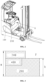
- FIG. 2 is a schematic structural diagram of a specific embodiment of a reach truck with a special structure for lithium battery provided by the present application
- FIG. 3 is a schematic diagram of the structure of the reach truck with a special structure for lithium battery shown in FIG. 2 in an A-direction
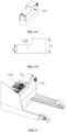
- FIG. 4-1 is a schematic structural diagram of a lithium battery in a reach truck with a special structure for lithium battery provided by the present application
- FIG. 4-2 is a front view of the lithium battery in the reach truck with a special structure for lithium battery provided by the present application
- FIG. 5 is a schematic diagram of the position and structure of the lithium battery in the reach truck with a special structure for lithium battery provided by the present application
- FIG. 1 is a schematic structural diagram of a specific embodiment of a reach truck with a special structure for lithium battery provided by the present application
- FIG. 3 is a schematic diagram of the structure of the reach truck with a special structure for lithium battery shown in FIG. 2 in an A-direction
- FIG. 4-1 is a schematic structural diagram of
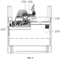
- FIG. 6 is a schematic diagram of the position of a multi-way valve and an operating assembly in the reach truck with a special structure for lithium battery provided by the present application
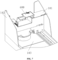
- FIG. 7 is a schematic diagram of a multi-way valve mounting bracket and a frame in the reach truck with a special structure for lithium battery provided by the present application
- FIG. 8-1 is a schematic diagram of the upper part of the frame of the reach truck with a special structure for lithium battery provided by the present application
- FIG. 8-2 is a schematic diagram of the lower part of the frame of the reach truck with a special structure for lithium battery provided by the present application
- FIG. 9-1 is a side view of a right leg of the counterweight in the reach truck with a special structure for lithium battery provided by the present application
- FIG. 9-2 is a A-A cross-sectional view of the right leg of the counterweight in the reach truck with a special structure for lithium battery shown in FIG. 9-1;
- FIG. 9-3 is a front view of the right leg of the counterweight in the reach truck with a special structure for lithium battery provided by the present application;
- FIG. 10-1 is an axonometric view of a rear panel in the reach truck with a special structure for lithium battery provided by the present application;
- FIG. 10-2 is a front view of the rear panel of the reach truck with a special structure for lithium battery provided by the present application;
- FIG. 10-3 is a sectional view of A-A in the rear panel shown in FIG. 10-2 ;
- FIG. 10-4 is a sectional view of B-B in the rear panel shown in FIG.
- FIG. 10-2 is a sectional view of C-C in the rear panel shown in FIG. 10-2 ;
- FIG. 11 is a front view of the frame of the reach truck with a special structure for lithium battery provided by the present application;
- FIG. 12 is a schematic diagram of the regional functions of the frame of the reach truck with a special structure for lithium battery provided by the present application;
- FIG. 13 is a schematic structural diagram of a multi-way valve mounting bracket in the reach truck with a special structure for lithium battery provided by the present application;
- FIG. 14 is a schematic structural diagram of another reach truck with a special structure for lithium battery provided by the present application.
- the reach truck with a special structure for lithium battery includes a frame 100, a lithium battery 200 and a controller assembly 400.
- the lithium battery 200 and the controller assembly 400 are both mounted on the frame 100;
- the frame 100 includes a bottom plate 103, a side plate 102 and a partition plate 101 located on the upper side of the bottom plate 103.
- the number of side plates 102 is at least two, and the side plates 102 are located on the left and right sides of the bottom plate 103 and the partition plate 101.
- a battery compartment into which the lithium battery 200 is placed is formed between the partition plates 101, the bottom plate 103 and the side plate 102.
- a concave portion is arranged on the partition plate 101.
- the partition plate 101 can be formed by bending, and the partition plate 101 is preferably sheet metal; the controller assembly 400 is placed at the position of the upper concave portion of the partition plate 101. That is, the position of the controller assembly 400 is lowered to the position of the concave portion.
- the shape of the lithium battery 200 corresponds to the shape of the battery compartment.
- the upper part of the lithium battery 200 is also provided with a concave portion corresponding to the position of the concave portion of the partition plate 101.
- the height n of one side of the lithium battery 200 is less than the height N of the other side of the lithium battery 200.
- the lithium battery can be in a laterally placed L-shaped structure.
- the lithium battery 200 is configured in a stepped special shape, which can be effectively fitted with the position of the concave portion under the premise of satisfying the capacity of the lithium battery 200.
- the reach truck with a special structure for lithium batteries provided by the present application, by adjusting the structure of the partition plate 101, the space of the battery compartment is changed, and the structure of the lithium battery 200 is adjusted.
- the controller assembly 400 is placed in the concave portion, which can effectively save space, reduce the installation height of the controller assembly 400, and effectively improve the driver's field of vision.
- the truck has better ergonomics, which is mainly in respect of a wider operating field of vision and a more spacious operating space.
- the battery compartment is in a concave shape, as shown in FIG. 6 and FIG. 11 .
- the above arrangement can meet the installation requirements of the controller assembly 400.
- the area B shown in FIG. 12 is used as the arrangement space of the controller assembly 400 while the installation space of the lithium battery 200 is sufficient.
- the area C shown in FIG. 12 is used as the space for receiving the lithium battery 200, and components, mainly the controller assembly 400, are arranged above the lithium battery 200, i.e., above the upper part of the concave portion of the lithium battery 200, so as to be complementary to the stepped shape of the lithium battery 200, forming a complete rectangular parallelepiped as a whole.
- the battery compartment is designed with a special-shaped structure, such as a concave-shaped structure, so that the component layout can make full use of the space.
- the battery compartment may also be in other shapes, any structure that may facilitate the arrangement of the controller assembly and save space can be used.
- the top of the lithium battery 200 is provided with a step.
- the lower-surface portion of the step of the lithium battery 200 corresponds to the position of the concave portion of the partition plate 101, which facilitates the installation of the lithium battery 200 and maximizes the utilization rate of the battery compartment.
- a wire harness is provided on a side of the lower-surface portion of the step of the lithium battery 200 away from the high-surface portion of the step of the lithium battery; a wire harness area for placing wire harnesses is provided in the battery compartment, such as area A shown in FIG. 12 , which is used as the wire harness space for the lithium battery 200.
- the frame 100 further includes a rear panel 106 located on the rear side of the bottom plate 103.
- the rear panel 106 includes a panel body 106-1, a main plate 106-2 and a steering wheel baffle 106-3.
- the panel body 106-1, the main plate 106-2 and the steering wheel baffle 106-3 are all solid counterweight plates. As shown in FIG. 10-1 to FIG. 10-4 , the panel body 106-1 extends in the longitudinal direction; the main plate 106-2 extends in the horizontal direction. The thickness of the panel body 106-1, the main plate 106-2 and the steering wheel baffle 106-3 can be increased in order to increase the counterweight.
- the counterweight of the rear panel 106 makes an improvement compared with the rear panel 106 of the frame structure in the vehicle of conventional technology. In order to achieve the effect of counterweight and make full use of the space, this part of the structure is made into a special shape so as to increase the weight as much as possible without affecting the layout of other components.
- the structure of the rear panel 106 can be made by tailor-welding many small-piece iron plates, or can be cast as a whole.
- the number of the steering wheel baffles 106-3 is at least two, and the baffles are arc-shaped; all of the steering wheel baffles 106-3 are surrounded to form an annular structure.
- the rotating shaft of the steering wheel of the truck can pass through the annular structure.
- the steering wheel baffle 106-3 is set in an arc shape because the panel body 106-1, the main plate 106-2 and the steering wheel baffle 106-3 are all solid counterweight plates, which are thick and occupy large space. Therefore, the steering wheel baffle plates 106-3 are configured in an arc shape so as to provide more space on both sides of the surface of the rear panel 106 in order to mount accessories such as a hydraulic oil tank.
- the frame 100 further includes a left leg portion 105 and a right leg portion 104, and the rear panel 106 is connected between the left leg portion 105 and the right leg portion 104; the left leg portion 105 is a weighted left leg with a solid structure, and the right leg portion 104 is a weighted right leg with a solid structure, thereby effectively increasing the bottom weight of the frame 100 and improving the stability of the frame 100 without occupying too much space.
- the reach truck with a special structure for lithium battery further includes a multi-way valve operating assembly 500 and a multi-way valve mounting bracket 600, the multi-way valve mounting bracket 600 is fixedly mounted on the partition plate 101, and the multi-way valve mounting bracket 600 is suspended above the concave portion of the partition plate 101.
- the multi-way valve operating assembly 500 is mounted on the multi-way valve mounting bracket 600.
- the multi-way valve mounting bracket 600 is suspended above the concave portion of the partition plate 101, so that the multi-way valve operating assembly 500 is arranged on the upper part of the controller assembly 400.
- the space of the multi-way valve operating assembly 500 in the conventional technology can be made free, which can effectively improve the space and field of view of the cab.
- both the height m of the operating platform and the height h of the battery compartment of the electric truck are greatly reduced compared with the conventional technology. More importantly, a visible area F is obtained, which is the position of the driver's knee, and it is also the position of the driver's line of sight at the lower right front, and thus this visible area F expands the driver's operating space and visual field.
- the multi-way valve operating assembly 500 is arranged above the controller assembly 400.
- the multi-way valve operating assembly 500 is separated from the controller assembly 400 by the multi-way valve mounting bracket 600 to realize electro-hydraulic separation, as shown in FIG. 6 .
- the multi-way valve operating assembly 500 is fixedly mounted on the multi-way valve mounting bracket 600, and the multi-way valve mounting bracket 600 is fixedly mounted on the frame 100, as shown in FIG. 7 .
- the multi-way valve mounting bracket 600 includes a multi-way valve mounting panel and an oil pipe fixing panel.
- the height of the oil pipe fixing panel is lower than the height of the multi-way valve mounting panel.
- baffles 602 are provided on the periphery of the multi-way valve mounting panel and the oil pipe fixing panel, and a gap for the oil to flow down is provided between the multi-way valve mounting panel and the oil pipe fixing panel.
- an oil pipe 601 is provided on a side of the oil pipe fixing panel.
- the shape of the multi-way valve mounting bracket 600 is shown in FIG. 13 .
- the multi-way valve mounting bracket 600 is in a stepped shape, and a multi-way valve mounting panel is arranged at the high-step position.
- the oil pipe fixing panel is located at the low-step position.
- Baffles 602 are arranged around the high-step surface and low-step surface to prevent the oil from flowing out.
- the hole through which the bolt passes is mounted with a gasket to prevent oil leakage from the through hole.
- an oil pipe 601 is provided on the low-step surface of the multi-way valve mounting bracket 600, and an extra pipe can be connected to the outside of the oil pipe 601 to guide the leaked oil to other locations. In this way, even if the multi-way valve leaks, the oil is not able to flow to the lower controller assembly 400, which realizes "electro-hydraulic separation".
- the multi-way valve operating assembly 500 and the controller assembly 400 are arranged up and down, and the structure is compact, which provides the aforementioned visual area F for the cab, and improves the space and field of view of the cab.
- the electric truck provided by this embodiment integrates the required counterweight into the frame 100, which are mainly distributed on the rear panel 106, the left leg portion 105 and the right leg portion 104, so that the center of gravity of the whole vehicle is lower and the stability of the whole vehicle is better.
- the counterweight is integrated into the frame 100, and thus the lithium battery 200 will no longer require additional counterweights. Therefore, the advantage of the small size of the lithium battery 200 can be used to reduce the height of the battery compartment, thereby reducing the height of the operating platform, which may improve the comfort of operation and reduce the center of gravity of the driver's operation.
- the low-step part can be used to arrange components such as the controller assembly, making full use of the space.
- the multi-way valve operating assembly 500 is stacked and arranged above the controller assembly 400 through the multi-way valve mounting bracket 600.
- the space is fully utilized.
- the advantages are as follow: it frees a large space in front of the driver's right side, which not only improves the driver's operating space, especially the leg room, but also improves the driver's operating field of vision and the overall driving sense of openness.
- the multi-way valve operating assembly 500 includes a finger switch operating component and an electromagnetic multi-way valve 501.
- the finger switch manipulating part is located on the seat, and is connected with the electromagnetic multi-way valve 501 by electrical signals.
- the operation sequence is as follows: the finger switch manipulating part 502 ⁇ the controller assembly 400 ⁇ the electromagnetic multi-way valve 501 acts, for the above vehicle models, the structure of the frame 100 provided in this embodiment is also applicable.
- the structure of the frame 100 remains unchanged, and the position of the controller assembly 400 remains unchanged.
- the electromagnetic multi-way valve 501 is arranged on the sliding frame 700, and the sliding frame 700 is configured as a sub-frame, which can be moved forward and backward; the finger switch manipulating part 502 is above the controller assembly 400, which constitutes a complete set of mechanisms, the mechanism is connected and mounted with the seat, and floats with the up and down of the seat, which has good ergonomics.
- the structure of the frame 100 provided above, there is also sufficient space between the controller assembly 400 and the finger switch manipulating part 502, so that the finger switch manipulating part 502 cannot interfere with the controller assembly 400 when floating with the seat.
- the finger switch manipulating part 502 is connected with the seat and floats with the seat, which greatly improves the driver's operating comfort, and has a wide field of vision and operating space.
Landscapes
- Engineering & Computer Science (AREA)
- Transportation (AREA)
- Structural Engineering (AREA)
- Mechanical Engineering (AREA)
- Life Sciences & Earth Sciences (AREA)
- Civil Engineering (AREA)
- Geology (AREA)
- Chemical & Material Sciences (AREA)
- General Chemical & Material Sciences (AREA)
- Electrochemistry (AREA)
- Chemical Kinetics & Catalysis (AREA)
- Combustion & Propulsion (AREA)
- Aviation & Aerospace Engineering (AREA)
- Power Engineering (AREA)
- Manufacturing & Machinery (AREA)
- Sustainable Energy (AREA)
- Sustainable Development (AREA)
- Body Structure For Vehicles (AREA)
- Forklifts And Lifting Vehicles (AREA)
- Electric Propulsion And Braking For Vehicles (AREA)
Description
- The present application relates to the technical field of industrial trucks, and in particular to a reach truck with a structure for lithium battery.
- Most of the existing lithium battery reach trucks are powered by lead-acid batteries, which are mainly divided into two parts from top to bottom. The upper part is mainly equipped with main components such as multi-way valve, controller assembly and cover, and the lower part is lead-acid battery. The lead-acid battery has two functions for the vehicle: first, as a power source to provide electricity; second, because the lead-acid battery is heavy, it serves as the counterweight of the whole vehicle to prevent the vehicle from tipping over. Although the reach truck with lithium battery is gradually emerging, even for the model of lithium battery, the lead-acid battery is only replaced with lithium battery.
- As shown in
FIG. 1 , after replacing the battery from a lead-acid battery with alithium battery 200, due to the small size and light weight of thelithium battery 200, anadditional counterweight 300 needs to be added to reach the weight of the basic lead-acid battery model. Therefore, the existing reach truck withlithium battery 200 is mainly divided into three parts from top to bottom. The upper part remains unchanged at which main components such as multi-way valve, controller assembly, and cover are mainly arranged. The middle part islithium battery 200, and the lower part is additional counterweight. Of course, the middle part of thelithium battery 200 and the lower part of the additional weight may also be integrated as an assembly of lithium battery 200 (including the additional weight). In that case, the assembly of lithium battery 200 (including the additional weight) is equivalent to or even the same as the original lead-acid battery in terms of external dimensions. Therefore, compared with the existing lead-acid battery reach truck withlithium battery 200, this reach truck withlithium battery 200 is the same or similar except for some changes regarding the lithium battery. For the reach truck withlithium battery 200 in the conventional technology, although both thelithium batteries 200 are with a small size, after adding additional weights, the overall size is equivalent to the overall size of the existing lead-acid battery. Therefore, the advantage with small size of thelithium battery 200 is not that obviously. For the whole vehicle, although the power is replaced by alithium battery 200, the structure and size of the whole vehicle are still the same as those with the conventional lead-acid battery, especially for the size of the battery compartment, which is very high, affecting the vision and space in the cab accordingly. - Therefore, how to adjust the battery compartment layout of the lithium battery reach truck and improve the driver's operating vision is a technical problem that the technicians in this field need to be solved at present.
- The patent of
US11165116B2 US20190225469A1 discloses a truck, which comprises two wheel arms each coupled to a load wheel, a thrust mast positioned between the wheel arms, a drive unit comprising a steerable drive wheel, and a counterweight comprised of cast iron and positioned in a front region of the reach truck. The patent ofCN211496821U discloses a forward forklift, which comprises a forklift body assembly and a portal assembly. A forward-moving type battery unit is arranged below the front part of the vehicle body assembly; a driving system is arranged on one side of the rear left side; a balance wheel assembly is arranged on the other side; a control system is arranged below an operating system; a power system is arranged above the driving system; the battery unit is detachably connected with the portal assembly; the portal frame moves forwards to drive the battery to move out; a balance suspension system is connected between the driving system and the balance wheel assembly to achieve dynamic balance. The patent ofCN215626569U discloses a mounting structure of a forklift hydraulic oil tank, which comprises an oil tank body, a base, a fastener and a shock pad, the oil tank body and the base are detachably connected together through the fastener, and the shock pad is installed between the oil tank body and the base. A plurality of grooves with cylindrical inner surfaces are formed in the bottom of the oil tank body, the shock pads are installed in the grooves, the fasteners are connected with the shock pads through die vulcanization pressing films, the fasteners comprise bolts and steel plates, the bolts are connected with the steel plates in a welded mode, and external threads of the bolts are connected with internal threads of corresponding screw holes in the base. - An object according to the present application is to provide a reach truck with a special structure for lithium battery, which can effectively save space with a stable structure, a low center of gravity and a wide vision for operators.
- In order to achieve the above object, the following technical solutions are provided according to the present application.
- A reach truck with a special structure for lithium battery, including a frame and a lithium battery and a controller assembly mounted on the frame; the frame includes a bottom plate, side plates and a partition plate located on an upper side of the bottom plate, the side plates are located on the left and right sides of the bottom plate and the partition plate, a battery compartment for receiving the lithium battery is formed between the partition plate, the bottom plate and the side plates; a concave portion is arranged on the partition plate. The controller assembly is placed at the position of the concave portion of the partition plate. The shape of the lithium battery corresponds to the shape of the battery compartment. The reach truck with a special structure for lithium battery further comprises a multi-way valve operating assembly and a multi-way valve mounting bracket, the multi-way valve mounting bracket is fixedly mounted on the partition plate, and the multi-way valve mounting bracket is suspended above the concave portion of the partition plate, the multi-way valve operating assembly is mounted on the multi-way valve mounting bracket, the multi-way valve mounting bracket comprises a multi-way valve mounting panel and an oil pipe fixing panel, a height of the oil pipe fixing panel is lower than a height of the multi-way valve mounting panel, and baffles are arranged at the periphery of the multi-way valve mounting panel and the oil pipe fixing panel, a gap for oil to flow down is provided between the multi-way valve mounting panel and the oil pipe fixing panel. In the above arrangement, the multi-way valve mounting bracket is suspended above the concave portion of the partition plate, so that the multi-way valve operating assembly is arranged on the upper part of the controller assembly, the space of the multi-way valve operating assembly in the conventional technology can be made free, which can effectively improve the space and field of view of the cab.
- Preferably, the battery compartment is in a concave shape.
- Preferably, a step is provided at a top of the lithium battery, and the low-step surface of the lithium battery corresponds to the position of the concave portion of the partition plate.
- Preferably, a wire harness is provided on a side of the low-step surface of the lithium battery away from the high-step surface of the lithium battery; the battery compartment is provided with space for the wire harness into which the wire harness is placed.
- Preferably, the frame further includes a rear panel located on a rear side of the bottom plate. The rear panel includes a panel body, a main plate and a steering wheel baffle. The panel body, the main plate and the steering wheel baffle are all solid counterweight plates.
- Preferably, the number of the steering wheel baffles is at least two, and the baffles are arc-shaped; all the steering wheel baffles surrounds to form an annular structure.
- Preferably, the frame further includes a left leg portion and a right leg portion, and the rear panel is connected between the left leg portion and the right leg portion; the left leg portion is a weighted left leg with a solid structure, and the right leg portion is a weighted right leg with a solid structure.
- Preferably, an oil pipe is provided on a side of the oil pipe fixing panel.
- The reach truck with a special structure for lithium battery provided by the present application includes a frame and a lithium battery and controller assembly mounted on the frame; the frame includes a bottom plate, side plates and a partition plate located on an upper side of the bottom plate, the side plates are located on the left and right sides of the bottom plate and the partition plate, a battery compartment for receiving the lithium battery is formed between the partition plate, the bottom plate and the side plates; a concave portion is arranged on the partition plate. The controller assembly is placed at the position of the concave portion of the partition plate. The shape of the lithium battery corresponds to the shape of the battery compartment. In the reach truck with a special structure for lithium batteries provided by the present application, by adjusting the structure of the partition plate, the space of the battery compartment is changed, and the structure of the lithium battery is adjusted. The controller assembly is placed in the concave portion, which can effectively save space, reduce the installation height of the controller assembly, and effectively improve the driver's field of vision.
- For more clearly illustrating the technical solutions of embodiments of the present application or in the conventional technology, drawings referred to for describing the embodiments or the conventional technology will be briefly described hereinafter. Apparently, the drawings in the following description are only several examples of the present application, and for those skilled in the art, other drawings may be obtained based on these drawings without any creative efforts.
-
FIG. 1 is a schematic structural diagram of a lithium battery reach truck in the conventional technology; -
FIG. 2 is a schematic structural diagram of a specific embodiment of a reach truck with a special structure for lithium battery provided by the present application; -
FIG. 3 is a schematic diagram of structure of the reach truck with a special structure for lithium battery shown inFIG. 2 in an A-direction; -
FIG. 4-1 is a schematic structural diagram of a lithium battery in a reach truck with a special structure for lithium battery provided by the present application; -
FIG. 4-2 is a front view of the lithium battery in the reach truck with a special structure for lithium battery provided by the present application; -
FIG. 5 is a schematic diagram of the position and structure of the lithium battery in the reach truck with a special structure for lithium battery provided by the present application; -
FIG. 6 is a schematic diagram of the position of a multi-way valve and an operating assembly in the reach truck with a special structure for lithium battery provided by the present application; -
FIG. 7 is a schematic diagram of a multi-way valve mounting bracket and a frame in the reach truck with a special structure for lithium battery provided by the present application; -
FIG. 8-1 is a schematic diagram of the upper part of the frame of the reach truck with a special structure for lithium battery provided by the present application; -
FIG. 8-2 is a schematic diagram of the lower part of the frame of the reach truck with a special structure for lithium battery provided by the present application; -
FIG. 9-1 is a side view of a right leg of the counterweight in the reach truck with a special structure for lithium battery provided by the present application; -
FIG. 9-2 is a A-A cross-sectional view of the right leg of the counterweight in the reach truck with a special structure for lithium battery shown inFIG. 9-1 ; -
FIG. 9-3 is a front view of the right leg of the counterweight in the reach truck with a special structure for lithium battery provided by the present application; -
FIG. 10-1 is an axonometric view of a rear panel in the reach truck with a special structure for lithium battery provided by the present application; -
FIG. 10-2 is a front view of the rear panel of the reach truck with a special structure for lithium battery provided by the present application; -
FIG. 10-3 is a sectional view of A-A in the rear panel shown inFIG. 10-2 ; -
FIG. 10-4 is a sectional view of B-B in the rear panel shown inFIG. 10-2 ; -
FIG. 10-5 is a sectional view of C-C in the rear panel shown inFIG. 10-2 ; -
FIG. 11 is a front view of the frame of the reach truck with a special structure for lithium battery provided by the present application; -
FIG. 12 is a schematic diagram of the regional functions of the frame of the reach truck with a special structure for lithium battery provided by the present application; -
FIG. 13 is a schematic structural diagram of a multi-way valve mounting bracket in the reach truck with a special structure for lithium battery provided by the present application; -
FIG. 14 is a schematic structural diagram of another reach truck with a special structure for lithium battery provided by the present application; - Reference numerals in the figures: 100 frame; 101 partition plate; 102 side plate; 103 bottom plate; 104 right leg portion; 105 left leg portion; 106 rear panel; 106-1 panel body; 106-2 main plate; 106-3 steering wheel baffle; 200 lithium battery; 300 counterweight; 400 controller assembly; 500 multi-way valve operating assembly; 501 electromagnetic multi-way valve; 502 manipulating part; 600 multi-way valve mounting bracket; 601 oil pipe; 602 baffle; 700 sliding frame.
- A core of the present application is to provide a reach truck with a special structure for lithium battery, which may effectively save space, and improve the driver's operating field of vision.
- Technical solutions in the embodiments of the present application are clearly and completely described hereinafter in conjunction with the drawings in the embodiments of the present application. Apparently, the embodiments described in the following are only some embodiments of the present application, rather than all embodiments. Based on the embodiments in the present application, all of other embodiments, made by the person skilled in the art without any creative efforts, fall into the scope of protection of the present application.
- Referring to
FIG. 2 to FIG. 14 ,FIG. 2 is a schematic structural diagram of a specific embodiment of a reach truck with a special structure for lithium battery provided by the present application;FIG. 3 is a schematic diagram of the structure of the reach truck with a special structure for lithium battery shown inFIG. 2 in an A-direction;FIG. 4-1 is a schematic structural diagram of a lithium battery in a reach truck with a special structure for lithium battery provided by the present application;FIG. 4-2 is a front view of the lithium battery in the reach truck with a special structure for lithium battery provided by the present application;FIG. 5 is a schematic diagram of the position and structure of the lithium battery in the reach truck with a special structure for lithium battery provided by the present application;FIG. 6 is a schematic diagram of the position of a multi-way valve and an operating assembly in the reach truck with a special structure for lithium battery provided by the present application;FIG. 7 is a schematic diagram of a multi-way valve mounting bracket and a frame in the reach truck with a special structure for lithium battery provided by the present application;FIG. 8-1 is a schematic diagram of the upper part of the frame of the reach truck with a special structure for lithium battery provided by the present application;FIG. 8-2 is a schematic diagram of the lower part of the frame of the reach truck with a special structure for lithium battery provided by the present application;FIG. 9-1 is a side view of a right leg of the counterweight in the reach truck with a special structure for lithium battery provided by the present application;FIG. 9-2 is a A-A cross-sectional view of the right leg of the counterweight in the reach truck with a special structure for lithium battery shown inFIG. 9-1; FIG. 9-3 is a front view of the right leg of the counterweight in the reach truck with a special structure for lithium battery provided by the present application;FIG. 10-1 is an axonometric view of a rear panel in the reach truck with a special structure for lithium battery provided by the present application;FIG. 10-2 is a front view of the rear panel of the reach truck with a special structure for lithium battery provided by the present application;FIG. 10-3 is a sectional view of A-A in the rear panel shown inFIG. 10-2 ;FIG. 10-4 is a sectional view of B-B in the rear panel shown inFIG. 10-2 ;FIG. 10-5 is a sectional view of C-C in the rear panel shown inFIG. 10-2 ;FIG. 11 is a front view of the frame of the reach truck with a special structure for lithium battery provided by the present application;FIG. 12 is a schematic diagram of the regional functions of the frame of the reach truck with a special structure for lithium battery provided by the present application;FIG. 13 is a schematic structural diagram of a multi-way valve mounting bracket in the reach truck with a special structure for lithium battery provided by the present application;FIG. 14 is a schematic structural diagram of another reach truck with a special structure for lithium battery provided by the present application. - In this embodiment, the reach truck with a special structure for lithium battery includes a
frame 100, alithium battery 200 and acontroller assembly 400. Thelithium battery 200 and thecontroller assembly 400 are both mounted on theframe 100; - Specifically, the
frame 100 includes abottom plate 103, aside plate 102 and apartition plate 101 located on the upper side of thebottom plate 103. The number ofside plates 102 is at least two, and theside plates 102 are located on the left and right sides of thebottom plate 103 and thepartition plate 101. A battery compartment into which thelithium battery 200 is placed is formed between thepartition plates 101, thebottom plate 103 and theside plate 102. - Further, a concave portion is arranged on the
partition plate 101. Specifically, thepartition plate 101 can be formed by bending, and thepartition plate 101 is preferably sheet metal; thecontroller assembly 400 is placed at the position of the upper concave portion of thepartition plate 101. That is, the position of thecontroller assembly 400 is lowered to the position of the concave portion. The shape of thelithium battery 200 corresponds to the shape of the battery compartment. The upper part of thelithium battery 200 is also provided with a concave portion corresponding to the position of the concave portion of thepartition plate 101. As shown inFIG. 4-1 and FIG. 4-2 , the height n of one side of thelithium battery 200 is less than the height N of the other side of thelithium battery 200. For example, the lithium battery can be in a laterally placed L-shaped structure. Thelithium battery 200 is configured in a stepped special shape, which can be effectively fitted with the position of the concave portion under the premise of satisfying the capacity of thelithium battery 200. - In the reach truck with a special structure for lithium batteries provided by the present application, by adjusting the structure of the
partition plate 101, the space of the battery compartment is changed, and the structure of thelithium battery 200 is adjusted. Thecontroller assembly 400 is placed in the concave portion, which can effectively save space, reduce the installation height of thecontroller assembly 400, and effectively improve the driver's field of vision. The truck has better ergonomics, which is mainly in respect of a wider operating field of vision and a more spacious operating space. - On the basis of the above-mentioned embodiments, the battery compartment is in a concave shape, as shown in
FIG. 6 andFIG. 11 . The above arrangement can meet the installation requirements of thecontroller assembly 400. The area B shown inFIG. 12 is used as the arrangement space of thecontroller assembly 400 while the installation space of thelithium battery 200 is sufficient. The area C shown inFIG. 12 is used as the space for receiving thelithium battery 200, and components, mainly thecontroller assembly 400, are arranged above thelithium battery 200, i.e., above the upper part of the concave portion of thelithium battery 200, so as to be complementary to the stepped shape of thelithium battery 200, forming a complete rectangular parallelepiped as a whole. - Specifically, the battery compartment is designed with a special-shaped structure, such as a concave-shaped structure, so that the component layout can make full use of the space. Of course, the battery compartment may also be in other shapes, any structure that may facilitate the arrangement of the controller assembly and save space can be used.
- On the basis of the above-mentioned embodiments, the top of the
lithium battery 200 is provided with a step. The lower-surface portion of the step of thelithium battery 200 corresponds to the position of the concave portion of thepartition plate 101, which facilitates the installation of thelithium battery 200 and maximizes the utilization rate of the battery compartment. - On the basis of the above-mentioned embodiments, a wire harness is provided on a side of the lower-surface portion of the step of the
lithium battery 200 away from the high-surface portion of the step of the lithium battery; a wire harness area for placing wire harnesses is provided in the battery compartment, such as area A shown inFIG. 12 , which is used as the wire harness space for thelithium battery 200. - Further, due to the small size and light weight of the
lithium battery 200, an additional counterweight is required to complement for the weight. No additional counterweight is provided in the battery compartment, but the height of the whole battery compartment and operating platform is reduced with the advantage of the small-sized battery, and the counterweight is transferred and distributed on theframe 100. - Specifically, on the basis of the above-mentioned embodiments, the
frame 100 further includes arear panel 106 located on the rear side of thebottom plate 103. Therear panel 106 includes a panel body 106-1, a main plate 106-2 and a steering wheel baffle 106-3. The panel body 106-1, the main plate 106-2 and the steering wheel baffle 106-3 are all solid counterweight plates. As shown inFIG. 10-1 toFIG. 10-4 , the panel body 106-1 extends in the longitudinal direction; the main plate 106-2 extends in the horizontal direction. The thickness of the panel body 106-1, the main plate 106-2 and the steering wheel baffle 106-3 can be increased in order to increase the counterweight. The counterweight of therear panel 106 makes an improvement compared with therear panel 106 of the frame structure in the vehicle of conventional technology. In order to achieve the effect of counterweight and make full use of the space, this part of the structure is made into a special shape so as to increase the weight as much as possible without affecting the layout of other components. The structure of therear panel 106 can be made by tailor-welding many small-piece iron plates, or can be cast as a whole. - On the basis of the above-mentioned embodiments, the number of the steering wheel baffles 106-3 is at least two, and the baffles are arc-shaped; all of the steering wheel baffles 106-3 are surrounded to form an annular structure. The rotating shaft of the steering wheel of the truck can pass through the annular structure. The steering wheel baffle 106-3 is set in an arc shape because the panel body 106-1, the main plate 106-2 and the steering wheel baffle 106-3 are all solid counterweight plates, which are thick and occupy large space. Therefore, the steering wheel baffle plates 106-3 are configured in an arc shape so as to provide more space on both sides of the surface of the
rear panel 106 in order to mount accessories such as a hydraulic oil tank. - On the basis of the above-mentioned embodiments, the
frame 100 further includes aleft leg portion 105 and aright leg portion 104, and therear panel 106 is connected between theleft leg portion 105 and theright leg portion 104; theleft leg portion 105 is a weighted left leg with a solid structure, and theright leg portion 104 is a weighted right leg with a solid structure, thereby effectively increasing the bottom weight of theframe 100 and improving the stability of theframe 100 without occupying too much space. - On the basis of the above-mentioned embodiments, the reach truck with a special structure for lithium battery further includes a multi-way valve operating assembly 500 and a multi-way
valve mounting bracket 600, the multi-wayvalve mounting bracket 600 is fixedly mounted on thepartition plate 101, and the multi-wayvalve mounting bracket 600 is suspended above the concave portion of thepartition plate 101. The multi-wayvalve operating assembly 500 is mounted on the multi-wayvalve mounting bracket 600. The multi-wayvalve mounting bracket 600 is suspended above the concave portion of thepartition plate 101, so that the multi-wayvalve operating assembly 500 is arranged on the upper part of thecontroller assembly 400. In that case, the space of the multi-way valve operating assembly 500 in the conventional technology can be made free, which can effectively improve the space and field of view of the cab. - Specifically, by adjusting the structure of the battery compartment and configuring the multi-way
valve mounting bracket 600, both the height m of the operating platform and the height h of the battery compartment of the electric truck are greatly reduced compared with the conventional technology. More importantly, a visible area F is obtained, which is the position of the driver's knee, and it is also the position of the driver's line of sight at the lower right front, and thus this visible area F expands the driver's operating space and visual field. - Further, the multi-way
valve operating assembly 500 is arranged above thecontroller assembly 400. The multi-wayvalve operating assembly 500 is separated from thecontroller assembly 400 by the multi-wayvalve mounting bracket 600 to realize electro-hydraulic separation, as shown inFIG. 6 . The multi-wayvalve operating assembly 500 is fixedly mounted on the multi-wayvalve mounting bracket 600, and the multi-wayvalve mounting bracket 600 is fixedly mounted on theframe 100, as shown inFIG. 7 . - On the basis of the above-mentioned embodiments, the multi-way
valve mounting bracket 600 includes a multi-way valve mounting panel and an oil pipe fixing panel. The height of the oil pipe fixing panel is lower than the height of the multi-way valve mounting panel. In addition, baffles 602 are provided on the periphery of the multi-way valve mounting panel and the oil pipe fixing panel, and a gap for the oil to flow down is provided between the multi-way valve mounting panel and the oil pipe fixing panel. - On the basis of the above-mentioned embodiments, an
oil pipe 601 is provided on a side of the oil pipe fixing panel. - Specifically, the shape of the multi-way
valve mounting bracket 600 is shown inFIG. 13 . The multi-wayvalve mounting bracket 600 is in a stepped shape, and a multi-way valve mounting panel is arranged at the high-step position. The oil pipe fixing panel is located at the low-step position.Baffles 602 are arranged around the high-step surface and low-step surface to prevent the oil from flowing out. There are multiple through holes in the high-step position, which are suitable for the installation of multi-way valves and other components. The hole through which the bolt passes is mounted with a gasket to prevent oil leakage from the through hole. In addition, anoil pipe 601 is provided on the low-step surface of the multi-wayvalve mounting bracket 600, and an extra pipe can be connected to the outside of theoil pipe 601 to guide the leaked oil to other locations. In this way, even if the multi-way valve leaks, the oil is not able to flow to thelower controller assembly 400, which realizes "electro-hydraulic separation". In addition, the multi-way valve operating assembly 500 and thecontroller assembly 400 are arranged up and down, and the structure is compact, which provides the aforementioned visual area F for the cab, and improves the space and field of view of the cab. - The electric truck provided by this embodiment integrates the required counterweight into the
frame 100, which are mainly distributed on therear panel 106, theleft leg portion 105 and theright leg portion 104, so that the center of gravity of the whole vehicle is lower and the stability of the whole vehicle is better. The counterweight is integrated into theframe 100, and thus thelithium battery 200 will no longer require additional counterweights. Therefore, the advantage of the small size of thelithium battery 200 can be used to reduce the height of the battery compartment, thereby reducing the height of the operating platform, which may improve the comfort of operation and reduce the center of gravity of the driver's operation. Due to the innovative shape and structure of thelithium battery 200, which adopts a stepped shape, the low-step part can be used to arrange components such as the controller assembly, making full use of the space. On this basis, the multi-wayvalve operating assembly 500 is stacked and arranged above thecontroller assembly 400 through the multi-wayvalve mounting bracket 600. In that case, under the premise of realizing "electro-hydraulic separation", the space is fully utilized. The advantages are as follow: it frees a large space in front of the driver's right side, which not only improves the driver's operating space, especially the leg room, but also improves the driver's operating field of vision and the overall driving sense of openness. - It should be noted that the above introduction is based on the model of the mechanical valve, that is, the model with the manipulating
part 502 in a manual operating lever. Of course, the structure of theframe 100 provided in this embodiment may also be applied to other electric truck models, as shown inFIG. 14 . For a vehicle model using an electro-proportional valve, the multi-wayvalve operating assembly 500 includes a finger switch operating component and an electromagneticmulti-way valve 501. The finger switch manipulating part is located on the seat, and is connected with the electromagneticmulti-way valve 501 by electrical signals. The operation sequence is as follows: the fingerswitch manipulating part 502→ thecontroller assembly 400→ the electromagneticmulti-way valve 501 acts, for the above vehicle models, the structure of theframe 100 provided in this embodiment is also applicable. Specifically, the structure of theframe 100 remains unchanged, and the position of thecontroller assembly 400 remains unchanged. The electromagneticmulti-way valve 501 is arranged on the slidingframe 700, and the slidingframe 700 is configured as a sub-frame, which can be moved forward and backward; the fingerswitch manipulating part 502 is above thecontroller assembly 400, which constitutes a complete set of mechanisms, the mechanism is connected and mounted with the seat, and floats with the up and down of the seat, which has good ergonomics. With the structure of theframe 100 provided above, there is also sufficient space between thecontroller assembly 400 and the fingerswitch manipulating part 502, so that the fingerswitch manipulating part 502 cannot interfere with thecontroller assembly 400 when floating with the seat. For this type of electric truck, as the fingerswitch manipulating part 502 is connected with the seat and floats with the seat, which greatly improves the driver's operating comfort, and has a wide field of vision and operating space. - The above embodiments are described in a progressive manner. Each of the embodiments is mainly focused on describing its differences from other embodiments, and reference may be made among these embodiments with respect to the same or similar parts. The reach truck with a special structure for lithium battery provided by the present application is introduced in detail hereinbefore. The principle and embodiments of the present application are described through specific examples herein. The description of the above-described embodiments is merely used to facilitate understanding the method and core idea of the present application. It should be noted that, for those skilled in the art, many improvements and modifications may be further made to the present disclosure without departing from the scope of appended claims.
Claims (8)
- A reach truck with a special structure for lithium battery, comprising a frame (100) and a lithium battery (200) and a controller assembly (400) mounted on the frame (100); wherein the frame (100) comprises a bottom plate (103), side plates (102) and a partition plate (101) located on an upper side of the bottom plate (103), wherein the side plates (102) are located on the left and right sides of the bottom plate (103) and the partition plate (101), wherein a battery compartment for receiving the lithium battery (200) is formed between the partition plate (101), the bottom plate (103) and the side plates (102); wherein a concave portion is arranged on the partition plate (101), wherein the controller assembly (400) is placed at the position of the concave portion of the partition plate (101), wherein the shape of the lithium battery (200) corresponds to the shape of the battery compartment,
characterized in that,the reach truck with a special structure for lithium battery further comprises a multi-way valve operating assembly (500) and a multi-way valve mounting bracket (600), wherein the multi-way valve mounting bracket (600) is fixedly mounted on the partition plate (101), and the multi-way valve mounting bracket (600) is suspended above the concave portion of the partition plate (101), wherein the multi-way valve operating assembly (500) is mounted on the multi-way valve mounting bracket (600),and in thatthe multi-way valve mounting bracket (600) comprises a multi-way valve mounting panel and an oil pipe fixing panel, wherein a height of the oil pipe fixing panel is lower than a height of the multi-way valve mounting panel, and baffles (602) are arranged at the periphery of the multi-way valve mounting panel and the oil pipe fixing panel, wherein a gap for oil to flow down is provided between the multi-way valve mounting panel and the oil pipe fixing panel. - The reach truck with a special structure for lithium battery according to claim 1, wherein the battery compartment is in a concave shape.
- The reach truck with a special structure for lithium battery according to claim 1, wherein a step is provided at a top of the lithium battery (200), and the low-step surface of the lithium battery (200) corresponds to the position of the concave portion of the partition plate (101).
- The reach truck with a special structure for lithium battery according to claim 2 or 3, wherein a wire harness is provided on a side of the low-step surface of the lithium battery (200) away from the high-step surface of the lithium battery; wherein the battery compartment is provided with space for the wire harness into which the wire harness is placed.
- The reach truck with a special structure for lithium battery according to any one of the preceding claims, wherein the frame (100) further comprises a rear panel (106) located on a rear side of the bottom plate (103), wherein the rear panel (106) comprises an panel body (106-1), a main plate (106-2) and a steering wheel baffle (106-3), wherein the panel body (106-1), the main plate (106-2) and the steering wheel baffle (106-3) are all solid counterweight plates.
- The reach truck with a special structure for lithium battery according to claim 5, wherein the number of the steering wheel baffles (106-3) is at least two, and the baffles are arc-shaped; wherein all the steering wheel baffles (106-3) surround to form an annular structure.
- The reach truck with a special structure for lithium battery according to claim 5 or 6, wherein the frame (100) further comprises a left leg portion (105) and a right leg portion (104), and the rear panel (106) is connected between the left leg portion (105) and the right leg portion (104); wherein the left leg portion (105) is a weighted left leg with a solid structure, and the right leg portion (104) is a weighted right leg with a solid structure.
- The reach truck with a special structure for lithium battery according to any one of the preceding claims, wherein an oil pipe (601) is provided on a side of the oil pipe fixing panel.
Applications Claiming Priority (1)
| Application Number | Priority Date | Filing Date | Title |
|---|---|---|---|
| CN202210370919.4A CN114436174B (en) | 2022-04-11 | 2022-04-11 | Framework forward-moving type forklift special for lithium battery |
Publications (2)
| Publication Number | Publication Date |
|---|---|
| EP4261180A1 EP4261180A1 (en) | 2023-10-18 |
| EP4261180B1 true EP4261180B1 (en) | 2025-02-26 |
Family
ID=81359618
Family Applications (1)
| Application Number | Title | Priority Date | Filing Date |
|---|---|---|---|
| EP22209796.6A Active EP4261180B1 (en) | 2022-04-11 | 2022-11-28 | Reach truck with structure for lithium battery |
Country Status (2)
| Country | Link |
|---|---|
| EP (1) | EP4261180B1 (en) |
| CN (1) | CN114436174B (en) |
Families Citing this family (1)
| Publication number | Priority date | Publication date | Assignee | Title |
|---|---|---|---|---|
| WO2025226791A1 (en) * | 2024-04-26 | 2025-10-30 | Crown Equipment Corporation | Battery system for an industrial vehicle |
Family Cites Families (21)
| Publication number | Priority date | Publication date | Assignee | Title |
|---|---|---|---|---|
| GB977289A (en) * | 1962-06-26 | 1964-12-02 | Ransomes Sims & Jefferies Ltd | Improvements in or relating to battery driven masted fork lift trucks |
| JP3400261B2 (en) * | 1996-08-26 | 2003-04-28 | 日本輸送機株式会社 | Battery case of counter type battery forklift |
| DE102018101530A1 (en) * | 2018-01-24 | 2019-07-25 | Jungheinrich Aktiengesellschaft | Battery for a truck |
| DE102018101529A1 (en) * | 2018-01-24 | 2019-07-25 | Jungheinrich Aktiengesellschaft | Industrial truck with an electrical connector |
| EP3517483B1 (en) * | 2018-01-24 | 2025-12-17 | Jungheinrich Aktiengesellschaft | Reach truck with a counterweight |
| DE102018201892A1 (en) * | 2018-02-07 | 2019-08-08 | Jungheinrich Aktiengesellschaft | battery lock |
| CN208378331U (en) * | 2018-03-12 | 2019-01-15 | 浙江加力仓储设备股份有限公司 | A kind of compact-sized type storage-battery balancing weight fork truck |
| DE102018112548A1 (en) * | 2018-04-10 | 2019-10-10 | Still S.P.A. | Industrial truck with a driver's workplace comprising a driver's platform |
| CN108502812B (en) * | 2018-04-19 | 2023-08-18 | 浙江中力机械股份有限公司 | Fork truck and integral type battery box thereof |
| AU2019213323B2 (en) * | 2018-08-08 | 2024-08-29 | The Raymond Corporation | Systems and methods for a modular battery system |
| CN209797387U (en) * | 2018-11-23 | 2019-12-17 | 韶关比亚迪实业有限公司 | Forklift truck |
| US11233291B2 (en) * | 2019-04-03 | 2022-01-25 | The Raymond Corporation | Systems and methods for a modular battery system |
| WO2021072726A1 (en) * | 2019-10-18 | 2021-04-22 | 淄博火炬能源有限责任公司 | Lithium ion battery module for electric forklift truck, and power supply box |
| CN211004398U (en) * | 2019-12-05 | 2020-07-14 | 浙江吉鑫祥叉车制造有限公司 | Lithium battery forklift's electrical system mounting structure |
| CN211470668U (en) * | 2019-12-09 | 2020-09-11 | 海米之星(苏州)电动科技股份有限公司 | Fork truck with rear-mounted battery |
| CN211496821U (en) * | 2020-01-11 | 2020-09-15 | 浙江加力仓储设备股份有限公司 | Simple forward forklift |
| CN212161899U (en) * | 2020-05-07 | 2020-12-15 | 安徽合力股份有限公司 | Fork truck general type lithium battery box |
| CN214243670U (en) * | 2020-11-23 | 2021-09-21 | 浙江中力机械股份有限公司 | Counter-balanced forklift |
| CN214411415U (en) * | 2021-03-08 | 2021-10-15 | 浙江中力机械股份有限公司 | General battery package and have its electric fork truck |
| CN113501468B (en) * | 2021-07-22 | 2024-05-07 | 浙江加力仓储设备股份有限公司 | Three-fulcrum counterweight type forklift |
| CN215626569U (en) * | 2021-07-22 | 2022-01-25 | 杭叉集团股份有限公司 | Mounting structure of forklift hydraulic oil tank |
-
2022
- 2022-04-11 CN CN202210370919.4A patent/CN114436174B/en active Active
- 2022-11-28 EP EP22209796.6A patent/EP4261180B1/en active Active
Also Published As
| Publication number | Publication date |
|---|---|
| CN114436174B (en) | 2022-07-05 |
| CN114436174A (en) | 2022-05-06 |
| EP4261180A1 (en) | 2023-10-18 |
Similar Documents
| Publication | Publication Date | Title |
|---|---|---|
| CN114571976B (en) | Integrated structure of automobile body and battery package under integrated electric automobile | |
| EP4470812B1 (en) | Electric all-terrain vehicle | |
| EP4261180A1 (en) | Reach truck with structure for lithium battery | |
| EP4647279A1 (en) | Power assembly and vehicle having same | |
| CN219303839U (en) | Battery pack box, battery pack and vehicle | |
| CN111216795A (en) | A New Type Aluminum Full Frame Rear Subframe | |
| CN114684303B (en) | Frame of inverted motor tricycle and inverted motor tricycle | |
| CN213682281U (en) | Electric loader | |
| CN114687403A (en) | Electric construction machine and vehicle body thereof | |
| CN211004398U (en) | Lithium battery forklift's electrical system mounting structure | |
| EP4292848A1 (en) | Middle section structure of ctb vehicle lower body and vehicle | |
| CN221141105U (en) | Balance weight of electric forklift | |
| CN213623164U (en) | Lithium battery electric forklift frame | |
| CN213649320U (en) | Trackless rubber-tyred car | |
| CN213682282U (en) | Electric loader | |
| CN215949911U (en) | Fan shaft adopting semi-solid die-casting aluminum process | |
| CN221608975U (en) | Multifunctional balancing weight for electric loader | |
| CN112249987A (en) | Lithium battery electric forklift frame | |
| CN223864958U (en) | Beam assembly, frame and wide body vehicle | |
| CN221343847U (en) | Fork truck frame | |
| CN220692932U (en) | Large-tonnage high-voltage lithium battery forklift double-pump motor assembly | |
| CN114701592B (en) | Three-wheeled electric motorcycle | |
| CN206765809U (en) | A kind of aluminium alloy gearshift support | |
| CN209505462U (en) | A kind of selector mounting structure | |
| CN217478999U (en) | Balancing weight and forklift |
Legal Events
| Date | Code | Title | Description |
|---|---|---|---|
| PUAI | Public reference made under article 153(3) epc to a published international application that has entered the european phase |
Free format text: ORIGINAL CODE: 0009012 |
|
| STAA | Information on the status of an ep patent application or granted ep patent |
Free format text: STATUS: THE APPLICATION HAS BEEN PUBLISHED |
|
| AK | Designated contracting states |
Kind code of ref document: A1 Designated state(s): AL AT BE BG CH CY CZ DE DK EE ES FI FR GB GR HR HU IE IS IT LI LT LU LV MC ME MK MT NL NO PL PT RO RS SE SI SK SM TR |
|
| STAA | Information on the status of an ep patent application or granted ep patent |
Free format text: STATUS: REQUEST FOR EXAMINATION WAS MADE |
|
| 17P | Request for examination filed |
Effective date: 20240305 |
|
| RBV | Designated contracting states (corrected) |
Designated state(s): AL AT BE BG CH CY CZ DE DK EE ES FI FR GB GR HR HU IE IS IT LI LT LU LV MC ME MK MT NL NO PL PT RO RS SE SI SK SM TR |
|
| GRAP | Despatch of communication of intention to grant a patent |
Free format text: ORIGINAL CODE: EPIDOSNIGR1 |
|
| STAA | Information on the status of an ep patent application or granted ep patent |
Free format text: STATUS: GRANT OF PATENT IS INTENDED |
|
| RIC1 | Information provided on ipc code assigned before grant |
Ipc: H01M 50/244 20210101ALI20240906BHEP Ipc: H01M 10/052 20100101ALI20240906BHEP Ipc: H01M 50/249 20210101ALI20240906BHEP Ipc: B66F 9/22 20060101ALI20240906BHEP Ipc: B60L 50/60 20190101ALI20240906BHEP Ipc: B60L 53/80 20190101ALI20240906BHEP Ipc: B60K 1/04 20190101ALI20240906BHEP Ipc: B66F 9/075 20060101AFI20240906BHEP |
|
| INTG | Intention to grant announced |
Effective date: 20241010 |
|
| GRAS | Grant fee paid |
Free format text: ORIGINAL CODE: EPIDOSNIGR3 |
|
| GRAA | (expected) grant |
Free format text: ORIGINAL CODE: 0009210 |
|
| STAA | Information on the status of an ep patent application or granted ep patent |
Free format text: STATUS: THE PATENT HAS BEEN GRANTED |
|
| AK | Designated contracting states |
Kind code of ref document: B1 Designated state(s): AL AT BE BG CH CY CZ DE DK EE ES FI FR GB GR HR HU IE IS IT LI LT LU LV MC ME MK MT NL NO PL PT RO RS SE SI SK SM TR |
|
| REG | Reference to a national code |
Ref country code: GB Ref legal event code: FG4D |
|
| REG | Reference to a national code |
Ref country code: CH Ref legal event code: EP |
|
| REG | Reference to a national code |
Ref country code: DE Ref legal event code: R096 Ref document number: 602022011065 Country of ref document: DE |
|
| REG | Reference to a national code |
Ref country code: IE Ref legal event code: FG4D |
|
| REG | Reference to a national code |
Ref country code: NL Ref legal event code: MP Effective date: 20250226 |
|
| PG25 | Lapsed in a contracting state [announced via postgrant information from national office to epo] |
Ref country code: RS Free format text: LAPSE BECAUSE OF FAILURE TO SUBMIT A TRANSLATION OF THE DESCRIPTION OR TO PAY THE FEE WITHIN THE PRESCRIBED TIME-LIMIT Effective date: 20250526 |
|
| PG25 | Lapsed in a contracting state [announced via postgrant information from national office to epo] |
Ref country code: FI Free format text: LAPSE BECAUSE OF FAILURE TO SUBMIT A TRANSLATION OF THE DESCRIPTION OR TO PAY THE FEE WITHIN THE PRESCRIBED TIME-LIMIT Effective date: 20250226 |
|
| PG25 | Lapsed in a contracting state [announced via postgrant information from national office to epo] |
Ref country code: PL Free format text: LAPSE BECAUSE OF FAILURE TO SUBMIT A TRANSLATION OF THE DESCRIPTION OR TO PAY THE FEE WITHIN THE PRESCRIBED TIME-LIMIT Effective date: 20250226 |
|
| PG25 | Lapsed in a contracting state [announced via postgrant information from national office to epo] |
Ref country code: ES Free format text: LAPSE BECAUSE OF FAILURE TO SUBMIT A TRANSLATION OF THE DESCRIPTION OR TO PAY THE FEE WITHIN THE PRESCRIBED TIME-LIMIT Effective date: 20250226 |
|
| REG | Reference to a national code |
Ref country code: LT Ref legal event code: MG9D |
|
| PG25 | Lapsed in a contracting state [announced via postgrant information from national office to epo] |
Ref country code: NO Free format text: LAPSE BECAUSE OF FAILURE TO SUBMIT A TRANSLATION OF THE DESCRIPTION OR TO PAY THE FEE WITHIN THE PRESCRIBED TIME-LIMIT Effective date: 20250526 Ref country code: IS Free format text: LAPSE BECAUSE OF FAILURE TO SUBMIT A TRANSLATION OF THE DESCRIPTION OR TO PAY THE FEE WITHIN THE PRESCRIBED TIME-LIMIT Effective date: 20250626 |
|
| PG25 | Lapsed in a contracting state [announced via postgrant information from national office to epo] |
Ref country code: NL Free format text: LAPSE BECAUSE OF FAILURE TO SUBMIT A TRANSLATION OF THE DESCRIPTION OR TO PAY THE FEE WITHIN THE PRESCRIBED TIME-LIMIT Effective date: 20250226 |
|
| PG25 | Lapsed in a contracting state [announced via postgrant information from national office to epo] |
Ref country code: HR Free format text: LAPSE BECAUSE OF FAILURE TO SUBMIT A TRANSLATION OF THE DESCRIPTION OR TO PAY THE FEE WITHIN THE PRESCRIBED TIME-LIMIT Effective date: 20250226 |
|
| PG25 | Lapsed in a contracting state [announced via postgrant information from national office to epo] |
Ref country code: PT Free format text: LAPSE BECAUSE OF FAILURE TO SUBMIT A TRANSLATION OF THE DESCRIPTION OR TO PAY THE FEE WITHIN THE PRESCRIBED TIME-LIMIT Effective date: 20250626 Ref country code: LV Free format text: LAPSE BECAUSE OF FAILURE TO SUBMIT A TRANSLATION OF THE DESCRIPTION OR TO PAY THE FEE WITHIN THE PRESCRIBED TIME-LIMIT Effective date: 20250226 |
|
| PG25 | Lapsed in a contracting state [announced via postgrant information from national office to epo] |
Ref country code: GR Free format text: LAPSE BECAUSE OF FAILURE TO SUBMIT A TRANSLATION OF THE DESCRIPTION OR TO PAY THE FEE WITHIN THE PRESCRIBED TIME-LIMIT Effective date: 20250527 Ref country code: BG Free format text: LAPSE BECAUSE OF FAILURE TO SUBMIT A TRANSLATION OF THE DESCRIPTION OR TO PAY THE FEE WITHIN THE PRESCRIBED TIME-LIMIT Effective date: 20250226 |
|
| REG | Reference to a national code |
Ref country code: AT Ref legal event code: MK05 Ref document number: 1770498 Country of ref document: AT Kind code of ref document: T Effective date: 20250226 |
|
| PG25 | Lapsed in a contracting state [announced via postgrant information from national office to epo] |
Ref country code: SE Free format text: LAPSE BECAUSE OF FAILURE TO SUBMIT A TRANSLATION OF THE DESCRIPTION OR TO PAY THE FEE WITHIN THE PRESCRIBED TIME-LIMIT Effective date: 20250226 |
|
| PG25 | Lapsed in a contracting state [announced via postgrant information from national office to epo] |
Ref country code: SM Free format text: LAPSE BECAUSE OF FAILURE TO SUBMIT A TRANSLATION OF THE DESCRIPTION OR TO PAY THE FEE WITHIN THE PRESCRIBED TIME-LIMIT Effective date: 20250226 |
|
| PG25 | Lapsed in a contracting state [announced via postgrant information from national office to epo] |
Ref country code: DK Free format text: LAPSE BECAUSE OF FAILURE TO SUBMIT A TRANSLATION OF THE DESCRIPTION OR TO PAY THE FEE WITHIN THE PRESCRIBED TIME-LIMIT Effective date: 20250226 |
|
| PG25 | Lapsed in a contracting state [announced via postgrant information from national office to epo] |
Ref country code: IT Free format text: LAPSE BECAUSE OF FAILURE TO SUBMIT A TRANSLATION OF THE DESCRIPTION OR TO PAY THE FEE WITHIN THE PRESCRIBED TIME-LIMIT Effective date: 20250226 |
|
| PG25 | Lapsed in a contracting state [announced via postgrant information from national office to epo] |
Ref country code: AT Free format text: LAPSE BECAUSE OF FAILURE TO SUBMIT A TRANSLATION OF THE DESCRIPTION OR TO PAY THE FEE WITHIN THE PRESCRIBED TIME-LIMIT Effective date: 20250226 |
|
| PG25 | Lapsed in a contracting state [announced via postgrant information from national office to epo] |
Ref country code: EE Free format text: LAPSE BECAUSE OF FAILURE TO SUBMIT A TRANSLATION OF THE DESCRIPTION OR TO PAY THE FEE WITHIN THE PRESCRIBED TIME-LIMIT Effective date: 20250226 Ref country code: CZ Free format text: LAPSE BECAUSE OF FAILURE TO SUBMIT A TRANSLATION OF THE DESCRIPTION OR TO PAY THE FEE WITHIN THE PRESCRIBED TIME-LIMIT Effective date: 20250226 |
|
| PG25 | Lapsed in a contracting state [announced via postgrant information from national office to epo] |
Ref country code: RO Free format text: LAPSE BECAUSE OF FAILURE TO SUBMIT A TRANSLATION OF THE DESCRIPTION OR TO PAY THE FEE WITHIN THE PRESCRIBED TIME-LIMIT Effective date: 20250226 |
|
| PG25 | Lapsed in a contracting state [announced via postgrant information from national office to epo] |
Ref country code: SK Free format text: LAPSE BECAUSE OF FAILURE TO SUBMIT A TRANSLATION OF THE DESCRIPTION OR TO PAY THE FEE WITHIN THE PRESCRIBED TIME-LIMIT Effective date: 20250226 |
|
| REG | Reference to a national code |
Ref country code: DE Ref legal event code: R097 Ref document number: 602022011065 Country of ref document: DE |
|
| PLBE | No opposition filed within time limit |
Free format text: ORIGINAL CODE: 0009261 |
|
| STAA | Information on the status of an ep patent application or granted ep patent |
Free format text: STATUS: NO OPPOSITION FILED WITHIN TIME LIMIT |
|
| PGFP | Annual fee paid to national office [announced via postgrant information from national office to epo] |
Ref country code: FR Payment date: 20251128 Year of fee payment: 4 |
|
| 26N | No opposition filed |
Effective date: 20251127 |
|
| PGFP | Annual fee paid to national office [announced via postgrant information from national office to epo] |
Ref country code: DE Payment date: 20251231 Year of fee payment: 4 |