EP4261141B1 - Synchronous spacing-changing conveyor device and blister cartoning integrated machine using the same - Google Patents
Synchronous spacing-changing conveyor device and blister cartoning integrated machine using the same Download PDFInfo
- Publication number
- EP4261141B1 EP4261141B1 EP22871103.2A EP22871103A EP4261141B1 EP 4261141 B1 EP4261141 B1 EP 4261141B1 EP 22871103 A EP22871103 A EP 22871103A EP 4261141 B1 EP4261141 B1 EP 4261141B1
- Authority
- EP
- European Patent Office
- Prior art keywords
- conveyor device
- pushing
- blister
- grid
- cartoning
- Prior art date
- Legal status (The legal status is an assumption and is not a legal conclusion. Google has not performed a legal analysis and makes no representation as to the accuracy of the status listed.)
- Active
Links
Images


Classifications
-
- B—PERFORMING OPERATIONS; TRANSPORTING
- B65—CONVEYING; PACKING; STORING; HANDLING THIN OR FILAMENTARY MATERIAL
- B65B—MACHINES, APPARATUS OR DEVICES FOR, OR METHODS OF, PACKAGING ARTICLES OR MATERIALS; UNPACKING
- B65B35/00—Supplying, feeding, arranging or orientating articles to be packaged
- B65B35/30—Arranging and feeding articles in groups
- B65B35/36—Arranging and feeding articles in groups by grippers
- B65B35/38—Arranging and feeding articles in groups by grippers by suction-operated grippers
-
- B—PERFORMING OPERATIONS; TRANSPORTING
- B65—CONVEYING; PACKING; STORING; HANDLING THIN OR FILAMENTARY MATERIAL
- B65B—MACHINES, APPARATUS OR DEVICES FOR, OR METHODS OF, PACKAGING ARTICLES OR MATERIALS; UNPACKING
- B65B35/00—Supplying, feeding, arranging or orientating articles to be packaged
- B65B35/30—Arranging and feeding articles in groups
- B65B35/40—Arranging and feeding articles in groups by reciprocating or oscillatory pushers
- B65B35/405—Arranging and feeding articles in groups by reciprocating or oscillatory pushers linked to endless conveyors
-
- B—PERFORMING OPERATIONS; TRANSPORTING
- B65—CONVEYING; PACKING; STORING; HANDLING THIN OR FILAMENTARY MATERIAL
- B65B—MACHINES, APPARATUS OR DEVICES FOR, OR METHODS OF, PACKAGING ARTICLES OR MATERIALS; UNPACKING
- B65B35/00—Supplying, feeding, arranging or orientating articles to be packaged
- B65B35/30—Arranging and feeding articles in groups
- B65B35/44—Arranging and feeding articles in groups by endless belts or chains
-
- B—PERFORMING OPERATIONS; TRANSPORTING
- B65—CONVEYING; PACKING; STORING; HANDLING THIN OR FILAMENTARY MATERIAL
- B65B—MACHINES, APPARATUS OR DEVICES FOR, OR METHODS OF, PACKAGING ARTICLES OR MATERIALS; UNPACKING
- B65B59/00—Arrangements to enable machines to handle articles of different sizes, to produce packages of different sizes, to vary the contents of packages, to handle different types of packaging material, or to give access for cleaning or maintenance purposes
- B65B59/001—Arrangements to enable adjustments related to the product to be packaged
-
- B—PERFORMING OPERATIONS; TRANSPORTING
- B65—CONVEYING; PACKING; STORING; HANDLING THIN OR FILAMENTARY MATERIAL
- B65B—MACHINES, APPARATUS OR DEVICES FOR, OR METHODS OF, PACKAGING ARTICLES OR MATERIALS; UNPACKING
- B65B59/00—Arrangements to enable machines to handle articles of different sizes, to produce packages of different sizes, to vary the contents of packages, to handle different types of packaging material, or to give access for cleaning or maintenance purposes
- B65B59/005—Adjustable conveying means
-
- B—PERFORMING OPERATIONS; TRANSPORTING
- B65—CONVEYING; PACKING; STORING; HANDLING THIN OR FILAMENTARY MATERIAL
- B65B—MACHINES, APPARATUS OR DEVICES FOR, OR METHODS OF, PACKAGING ARTICLES OR MATERIALS; UNPACKING
- B65B65/00—Details peculiar to packaging machines and not otherwise provided for; Arrangements of such details
- B65B65/02—Driving gear
-
- B—PERFORMING OPERATIONS; TRANSPORTING
- B65—CONVEYING; PACKING; STORING; HANDLING THIN OR FILAMENTARY MATERIAL
- B65G—TRANSPORT OR STORAGE DEVICES, e.g. CONVEYORS FOR LOADING OR TIPPING, SHOP CONVEYOR SYSTEMS OR PNEUMATIC TUBE CONVEYORS
- B65G47/00—Article or material-handling devices associated with conveyors; Methods employing such devices
- B65G47/22—Devices influencing the relative position or the attitude of articles during transit by conveyors
- B65G47/26—Devices influencing the relative position or the attitude of articles during transit by conveyors arranging the articles, e.g. varying spacing between individual articles
- B65G47/30—Devices influencing the relative position or the attitude of articles during transit by conveyors arranging the articles, e.g. varying spacing between individual articles during transit by a series of conveyors
- B65G47/32—Applications of transfer devices
-
- B—PERFORMING OPERATIONS; TRANSPORTING
- B65—CONVEYING; PACKING; STORING; HANDLING THIN OR FILAMENTARY MATERIAL
- B65G—TRANSPORT OR STORAGE DEVICES, e.g. CONVEYORS FOR LOADING OR TIPPING, SHOP CONVEYOR SYSTEMS OR PNEUMATIC TUBE CONVEYORS
- B65G47/00—Article or material-handling devices associated with conveyors; Methods employing such devices
- B65G47/52—Devices for transferring articles or materials between conveyors i.e. discharging or feeding devices
-
- B—PERFORMING OPERATIONS; TRANSPORTING
- B65—CONVEYING; PACKING; STORING; HANDLING THIN OR FILAMENTARY MATERIAL
- B65G—TRANSPORT OR STORAGE DEVICES, e.g. CONVEYORS FOR LOADING OR TIPPING, SHOP CONVEYOR SYSTEMS OR PNEUMATIC TUBE CONVEYORS
- B65G47/00—Article or material-handling devices associated with conveyors; Methods employing such devices
- B65G47/74—Feeding, transfer, or discharging devices of particular kinds or types
- B65G47/90—Devices for picking-up and depositing articles or materials
- B65G47/91—Devices for picking-up and depositing articles or materials incorporating pneumatic, e.g. suction, grippers
-
- B—PERFORMING OPERATIONS; TRANSPORTING
- B65—CONVEYING; PACKING; STORING; HANDLING THIN OR FILAMENTARY MATERIAL
- B65B—MACHINES, APPARATUS OR DEVICES FOR, OR METHODS OF, PACKAGING ARTICLES OR MATERIALS; UNPACKING
- B65B11/00—Wrapping, e.g. partially or wholly enclosing, articles or quantities of material, in strips, sheets or blanks, of flexible material
- B65B11/50—Enclosing articles, or quantities of material, by disposing contents between two sheets, e.g. pocketed sheets, and securing their opposed free margins
- B65B11/52—Enclosing articles, or quantities of material, by disposing contents between two sheets, e.g. pocketed sheets, and securing their opposed free margins one sheet being rendered plastic, e.g. by heating, and forced by fluid pressure, e.g. vacuum, into engagement with the other sheet and contents, e.g. skin-, blister-, or bubble- packaging
-
- B—PERFORMING OPERATIONS; TRANSPORTING
- B65—CONVEYING; PACKING; STORING; HANDLING THIN OR FILAMENTARY MATERIAL
- B65B—MACHINES, APPARATUS OR DEVICES FOR, OR METHODS OF, PACKAGING ARTICLES OR MATERIALS; UNPACKING
- B65B2220/00—Specific aspects of the packaging operation
- B65B2220/16—Packaging contents into primary and secondary packaging
-
- B—PERFORMING OPERATIONS; TRANSPORTING
- B65—CONVEYING; PACKING; STORING; HANDLING THIN OR FILAMENTARY MATERIAL
- B65B—MACHINES, APPARATUS OR DEVICES FOR, OR METHODS OF, PACKAGING ARTICLES OR MATERIALS; UNPACKING
- B65B5/00—Packaging individual articles in containers or receptacles, e.g. bags, sacks, boxes, cartons, cans, jars
- B65B5/06—Packaging groups of articles, the groups being treated as single articles
Definitions
- the present disclosure relates to a machine for packaging a medical article, and in particular, to a synchronous spacing-changing conveyor device and a blister cartoning integrated machine using the same.
- plastic blister supports packaged by a blister packaging machine are conveyed to a hopper of a cartoning machine through a conveyor belt or to a feeding station of the cartoning machine through a conveyor chain.
- the plastic blister supports are conveyed forward by a frictional force of the conveyor belt.
- the plastic blister supports have a slipping phenomenon on the conveyor belt. Particularly in the high-speed conveying process, due to the frictional force and inertial slipping, the plastic blister supports cannot accurately enter the feeding region of the hopper in the cartoning machine. Hence, large-scale synchronous linkage integrated packaging cannot be effectively realized.
- the conveyor chain usually uses a synchronous belt as a conveying base material. Stops are equidistantly provided on a surface of the synchronous belt to form the annular conveyor chain.
- the pitch changing device includes N holding units capable of holding the preforms and arranged at a predetermined pitch in a predetermined direction, N being an integer equal to or larger than 2; a coupling unit coupling the holding units adjacent to each other such that the pitch is changeable; drive unit configured to generate a predetermined drive force; and a drive force transmission unit configured to transmit the drive force to each of one end-side and the other end-side, in the predetermined direction, of the coupled N holding units, in which the one end-side and the other end-side are configured to be moved in the predetermined direction by the drive force to change the pitch.
- the present disclosure provides a synchronous spacing-changing conveyor device for realizing spacing-changing conveyance and a blister cartoning integrated machine using the synchronous spacing-changing conveyor device.
- a synchronous spacing-changing conveyor device includes a base, where a first slideway and a second slideway are provided side by side on the base; a plurality of first sliding seats are slidably provided on the first slideway; a first tray is provided on each of the first sliding seats; a plurality of second sliding seats are slidably provided on the second slideway; a second tray is provided on each of the second sliding seats; the first sliding seat is connected to a first hinge shaft with a rotation axis provided on the first sliding seat (311); two cross-connecting rods are hinged crosswise on the first hinge shaft; the second sliding seat is connected to a second hinge shaft with a rotation axis provided on the second sliding seat (312); two cross-connecting rods are hinged crosswise on the second hinge shaft; cross-connecting rods on two adjacent first sliding seat and second sliding seat are hinged crosswise in one-to-one correspondence; one of the first sliding seats is connected to a first transmission belt; the first transmission belt is in transmission connection with a first power source; one
- a first supporting seat is provided on the first sliding seat; the first tray is provided on the first supporting seat; a first locating pin is provided on the first supporting seat; a first locating hole for allowing the first locating pin to insert into is formed in the first tray; a second supporting seat is provided on the second sliding seat; the second tray is provided on the second supporting seat; a second locating pin is provided on the second supporting seat; and a second locating hole for allowing the second locating pin to insert into is formed in the second tray.
- a first locating fixture is provided on the first supporting seat; a first locating groove for allowing the first locating fixture to enter is formed at a bottom of the first tray; a second locating fixture is provided on the second supporting seat; and a second locating groove for allowing the second locating fixture to enter is formed at a bottom of the second tray.
- a blister cartoning integrated machine includes a blister packaging machine and a cartoning machine, where the blister packaging machine includes a discharging grid conveyor device for conveying packaged blisters out through the discharging grid conveyor device; the synchronous spacing-changing conveyor device is provided in front of the discharging grid conveyor device; a blister discharging transfer manipulator for transferring blisters on the discharging grid conveyor device to the synchronous spacing-changing conveyor device is provided above the discharging grid conveyor device; the blister discharging transfer manipulator includes a discharging vacuum nozzle; the cartoning machine comprises a feeding grid conveyor device for transferring packaged blisters from the synchronous spacing-changing conveyor device to the cartoning station of the cartoning machine for cartoning; the synchronous spacing-changing conveyor device is provided side by side with the feeding grid conveyor device; a blister feeding transfer manipulator for transferring blisters on the synchronous spacing-changing conveyor device to the feeding grid conveyor device is provided above the feeding grid conveyor device; and the blister feeding transfer manipulator includes a feeding vacuum nozzle.
- the discharging grid conveyor device includes a conveyor rack, a grid plate, first pushing plates, a first pushing plate transmission mechanism, and a pushing power source;
- the grid plate is provided with a feeding channel;
- the first pushing plates each are provided with a pushing portion capable of being located in the feeding channel;
- the first pushing plate transmission mechanism includes a first conveyor belt;
- the first pushing plates are connected to the first conveyor belt;
- the first conveyor belt is in transmission connection with the pushing power source, such that during operation blisters fall into the feeding channel of the grid plate, the pushing power source is configured to drive the first conveyor belt to move, the first conveyor belt is configured to drive the first pushing plates to move, and the pushing portions of the first pushing plates are configured to push the blisters in the feeding channel of the grid plate to move forward.
- the discharging grid conveyor device includes second pushing plates and a second pushing plate transmission mechanism; the second pushing plates and the first pushing plates are arranged at intervals; the second pushing plates each are provided with a pushing portion capable of being located in the feeding channel; the second pushing plate transmission mechanism includes a second conveyor belt; the second conveyor belt is provided side by side with the first conveyor belt; the second pushing plates are connected to the second conveyor belt; and the second conveyor belt is in transmission connection with the pushing power source, such that during operation blisters fall into the feeding channel of the grid plate, the pushing power source is configured to drive the second conveyor belt to move, the second conveyor belt (14) is configured to drive the second pushing plates (12) to move, and the pushing portions of the second pushing plates (12) are configured to push the blisters (C) in the feeding channel (150) of the grid plate (15) to move forward.
- an end of each of the second pushing plates and the first pushing plates is connected to a roller, and a roller walkway for allowing the roller to move is provided on the conveyor rack, such that the rollers are configured to move on the roller walkway while the pushing plates move.
- the discharging vacuum nozzle of the blister discharging transfer manipulator is provided on a rotating power source.
- the blister feeding transfer manipulator is configured to track blister suction and placement for realizing continuous conveyance between the synchronous spacing-changing conveyor device and the feeding grid conveyor device.
- the synchronous spacing-changing conveyor device provided by the present disclosure can realize spacing-changing conveyance. Therefore, the blister cartoning integrated machine using the synchronous spacing-changing conveyor device realizes linkage more conveniently.
- a blister cartoning integrated machine includes a blister packaging machine and a cartoning machine.
- the blister packaging machine includes discharging grid conveyor device 1.
- the blister packaging machine packages articles (such as prefilled syringes, penicillin bottles, and ampoule bottles) into blisters, and then conveys the blisters out through the discharging grid conveyor device 1.
- the cartoning machine includes feeding grid conveyor device 5.
- Packaged blisters are placed onto the feeding grid conveyor device 5, and conveyed by the feeding grid conveyor device 5 to a cartoning station of the cartoning machine for cartoning (carton packaging).
- the discharging grid conveyor device 1 has a different grid spacing from the feeding grid conveyor device.
- synchronous spacing-changing conveyor device 3 is provided in front of the discharging grid conveyor device 1.
- the synchronous spacing-changing conveyor device 3 is provided side by side with the feeding grid conveyor device 5.
- Blister discharging transfer manipulator 2 for transferring blisters on the discharging grid conveyor device 1 to the synchronous spacing-changing conveyor device 3 is provided above the discharging grid conveyor device 1.
- the blister discharging transfer manipulator 2 includes discharging vacuum nozzle 20.
- Blister feeding transfer manipulator 4 for transferring blisters on the synchronous spacing-changing conveyor device 3 to the feeding grid conveyor device 5 is provided above the feeding grid conveyor device 5.
- the blister feeding transfer manipulator 4 includes feeding vacuum nozzle 40.
- the blister cartoning integrated machine has the following working principle: Blisters are conveyed out from the discharging grid conveyor device 1 of the blister packaging machine.
- the blister discharging transfer manipulator 2 sucks the blisters on the discharging grid conveyor device 1 through the discharging vacuum nozzle 20, and transfers them to the synchronous spacing-changing conveyor device 3. While moving forward, the synchronous spacing-changing conveyor device 3 changes a spacing between the blisters (as shown in FIG. 6 ), until the spacing is the same as the spacing of the feeding grid conveyor device 5.
- the blister feeding transfer manipulator 4 sucks the blisters on the synchronous spacing-changing conveyor device 3 through the feeding vacuum nozzle 40, and transfers them to the feeding grid conveyor device 5.
- the feeding grid conveyor device 5 transfers the blisters to the cartoning station of the cartoning machine for cartoning.
- the present disclosure can greatly improve the linkage production efficiency between the blister packaging machine and the cartoning machine, and solves the problem of hard matching between blister packaging and cartoning in a specification change.
- Both the blister packaging machine and the cartoning machine are the prior art (refer to the patent application No. 201520906465.3 ).
- the blister discharging transfer manipulator is also the prior art (refer to the patent application No. 201910076327.X , in which the structure is the same, but the material to be sucked is different).
- the blister feeding transfer manipulator is also the prior art (refer to the patent application No. 202120863286.1 ).
- the blister cartoning integrated machine is novel for the synchronous spacing-changing conveyor device and the linkage layout using the synchronous spacing-changing conveyor device.
- the synchronous spacing-changing conveyor device 3 includes base 30. As shown in FIG. 5 , first slideway 301 and second slideway 302 are provided side by side on the base 30. A plurality of first sliding seats 311 are slidably provided on the first slideway 301. First tray 321 (the first tray 321 is provided with a placement groove into which a blister can be placed) is provided on each of the first sliding seats 311. A plurality of second sliding seats 312 are slidably provided on the second slideway 302. Second tray 322 (the second tray 321 is provided with a placement groove into which a blister can be placed) is provided on each of the second sliding seats 312. The first sliding seat 311 is connected to a hinge shaft.
- Two cross-connecting rods 31 are hinged crosswise on the hinge shaft.
- the second sliding seat 312 is also connected to a hinge shaft.
- Two cross-connecting rods 31 are hinged crosswise on the hinge shaft.
- Cross-connecting rods 31 on two adjacent first sliding seat 311 and second sliding seat 312 are hinged crosswise in one-to-one correspondence (to form a scissor-type structure).
- One of the first sliding seats 311 is connected to first transmission belt 351.
- the first transmission belt 351 is in transmission connection with first power source 361.
- One of the second sliding seats 312 is connected to second transmission belt 352.
- the second transmission belt 352 is in transmission connection with second power source 362.
- the synchronous spacing-changing conveyor device 3 has a following working principle: As shown in FIG. 6 and FIG. 7 , after blisters are placed onto the first tray 321 and the second tray 322, the first power source 361 drives the first transmission belt 351 to rotate. Since one of the first sliding seats 311 is connected to the first transmission belt 351, the first sliding seats 311 move on the first slideway 301. Likewise, the second power source 362 drives the second transmission belt 352 to rotate. Since one of the second sliding seats 312 is connected to the second transmission belt 352, the second sliding seats 312 move on the second slideway 302. The first sliding seats 311 are connected to the second sliding seats 312 through the cross-connecting rods 31, so all of the first sliding seats 311 and all of the second sliding seats 312 move.
- the discharging grid conveyor device 1 of the preceding blister packaging machine can be matched with the feeding grid conveyor device 5 of the following cartoning machine, no matter how the specification of the discharging grid conveyor device changes.
- first supporting seat 331 is provided on the first sliding seat 311.
- the first tray 321 is provided on the first supporting seat 311.
- First locating pin 371 is provided on the first supporting seat 331.
- a first locating hole for allowing the first locating pin 371 to insert into is formed in the first tray 321.
- a second supporting seat is provided on the second sliding seat 312.
- the second tray is provided on the second supporting seat.
- a second locating pin is provided on the second supporting seat.
- a second locating hole for allowing the second locating pin to insert into is formed in the second tray. When the second tray is replaced necessarily, the second locating pin is pulled out, and the second tray is taken down, which is very convenient.
- first locating fixture 341 is provided on the first supporting seat 321.
- a first locating groove for allowing the first locating fixture 341 to enter is formed at a bottom of the first tray 321.
- the first supporting seat 321 is clamped onto the first locating fixture 341 through the first locating groove, thereby preventing the rotation of the first tray 321.
- the second supporting seat is connected to a second locating fixture.
- a second locating groove for allowing the second locating fixture to enter is formed at a bottom of the second tray 322.
- the second tray 322 is clamped onto the second locating fixture through the second locating groove, thereby preventing the rotation of the second tray 322.
- the discharging grid conveyor device 1 of the blister packaging machine may use a common grid conveyor device.
- the present disclosure provides a novel grid conveyor device.
- the discharging grid conveyor device 1 includes conveyor rack 10, grid plate 15, first pushing plates 11, a first pushing plate transmission mechanism, and pushing power source 19.
- the grid plate 15 is provided with feeding channel 150.
- the first pushing plates 15 each are provided with pushing portion 110 capable of being located in the feeding channel 150.
- the first pushing plate transmission mechanism includes first conveyor belt 13.
- the first pushing plates 11 are connected to the first conveyor belt 13.
- the first conveyor belt 13 is in transmission connection with the pushing power source 19.
- trimmed blisters C fall into the feeding channel 150 of the grid plate 15.
- the pushing power source 19 drives the first conveyor belt 13 to move. Since the first pushing plates 11 are connected to the first conveyor belt 13, the first conveyor belt 13 drives the first pushing plates 11 to move, and the pushing portions 110 of the first pushing plates 11 push the blisters C to move forward.
- the discharging grid conveyor device 1 further includes second pushing plates 12 and a second pushing plate transmission mechanism.
- the second pushing plates 12 and the first pushing plates 11 are arranged at intervals.
- the second pushing plates 12 each are provided with a pushing portion located in the feeding channel 150.
- the second pushing plate transmission mechanism includes second conveyor belt 14.
- the second conveyor belt 14 is provided side by side with the first conveyor belt 13.
- the second pushing plates 12 are connected to the second conveyor belt 14.
- the second conveyor belt 14 is in transmission connection with the pushing power source 19.
- the second pushing plate 12 a same pushing principle as the first pushing plate 11, which is not repeated herein.
- roller 16 To support the pushing plates, an end of each of the second pushing plates 12 and the first pushing plates 11 is connected to roller 16.
- Roller walkway 17 for allowing the roller 16 to walk is provided on the conveyor rack 10. While the pushing plates move, the rollers 16 walk on the roller walkway 17 of the conveyor rack 10, thereby supporting the pushing plates and making the pushing plates walk more stably.
- the discharging vacuum nozzle 20 of the blister discharging transfer manipulator 2 is provided on a rotating power source, such that the blisters from the discharging grid conveyor device 1 to the synchronous spacing-changing conveyor device 3 are rotated by 90°, and the transverse blisters are placed longitudinally to meet requirements on cartoning positions.
- the rotating power source With the rotating power source, the discharging vacuum nozzle 20 is rotated by 90° in movement.
- the manipulator is rotated when there are many blisters in a longitudinal direction. In case of a small number of blisters in the longitudinal direction, the manipulator is unnecessarily rotated.
- the blister feeding transfer manipulator 4 can track blister suction and placement, such that the synchronous spacing-changing conveyor device 3 and the feeding grid conveyor device 5 realize continuous conveyance to improve the packaging efficiency.
Landscapes
- Engineering & Computer Science (AREA)
- Mechanical Engineering (AREA)
- Auxiliary Devices For And Details Of Packaging Control (AREA)
Description
- The present disclosure relates to a machine for packaging a medical article, and in particular, to a synchronous spacing-changing conveyor device and a blister cartoning integrated machine using the same.
- In pharmaceutical packaging and packaging technological process, and particularly in linkage packaging from blister packaging to cartoning for liquid preparations (prefilled syringes, penicillin bottles, and ampoule bottles), how to realize high-speed integrated linkage operation between the preceding blister packaging machine (for blister forming and packaging) and the following cartoning machine (for blister cartoning) in a relatively compact pharmaceutical packaging workshop has become a technical problem to the current core process in the pharmaceutical packaging industry. According to original solutions, plastic blister supports packaged by a blister packaging machine are conveyed to a hopper of a cartoning machine through a conveyor belt or to a feeding station of the cartoning machine through a conveyor chain. For the former method combined with the conveyor belt and the hopper, the plastic blister supports are conveyed forward by a frictional force of the conveyor belt. In this process, the plastic blister supports have a slipping phenomenon on the conveyor belt. Particularly in the high-speed conveying process, due to the frictional force and inertial slipping, the plastic blister supports cannot accurately enter the feeding region of the hopper in the cartoning machine. Hence, large-scale synchronous linkage integrated packaging cannot be effectively realized. For the latter method using the conveyor chain, the conveyor chain usually uses a synchronous belt as a conveying base material. Stops are equidistantly provided on a surface of the synchronous belt to form the annular conveyor chain. In case of a specification change in the preceding blister packaging, after a production batch and a packaging specification are changed, spacings between the plastic blister supports packaged by the blister packaging machine are not always the same, and the number of trimmed blister plastic supports also changes with an actual size of medicines, such that the whole conveyor chain is to be replaced. Moreover, the conventional conveyor chain using the synchronous belt that is difficult to be replaced needs to be calibrated for its origin in each replacement. This is inconvenient for the large-scale synchronous integrated linkage production in the pharmaceutical packaging and hardly adaptable to the integrated linkage packaging technological process in the whole pharmaceutical industry.
US2021/268714A1 discloses a pitch changing device, a molding device having the same and a molding method capable of addressing diverse pitches between preforms. The pitch changing device includes N holding units capable of holding the preforms and arranged at a predetermined pitch in a predetermined direction, N being an integer equal to or larger than 2; a coupling unit coupling the holding units adjacent to each other such that the pitch is changeable; drive unit configured to generate a predetermined drive force; and a drive force transmission unit configured to transmit the drive force to each of one end-side and the other end-side, in the predetermined direction, of the coupled N holding units, in which the one end-side and the other end-side are configured to be moved in the predetermined direction by the drive force to change the pitch. - In view of shortages in the prior art, the present disclosure provides a synchronous spacing-changing conveyor device for realizing spacing-changing conveyance and a blister cartoning integrated machine using the synchronous spacing-changing conveyor device.
- A synchronous spacing-changing conveyor device includes a base, where a first slideway and a second slideway are provided side by side on the base; a plurality of first sliding seats are slidably provided on the first slideway; a first tray is provided on each of the first sliding seats; a plurality of second sliding seats are slidably provided on the second slideway; a second tray is provided on each of the second sliding seats; the first sliding seat is connected to a first hinge shaft with a rotation axis provided on the first sliding seat (311); two cross-connecting rods are hinged crosswise on the first hinge shaft; the second sliding seat is connected to a second hinge shaft with a rotation axis provided on the second sliding seat (312); two cross-connecting rods are hinged crosswise on the second hinge shaft; cross-connecting rods on two adjacent first sliding seat and second sliding seat are hinged crosswise in one-to-one correspondence; one of the first sliding seats is connected to a first transmission belt; the first transmission belt is in transmission connection with a first power source; one of the second sliding seats is connected to a second transmission belt; and the second transmission belt is in transmission connection with a second power source.
- Preferably, a first supporting seat is provided on the first sliding seat; the first tray is provided on the first supporting seat; a first locating pin is provided on the first supporting seat; a first locating hole for allowing the first locating pin to insert into is formed in the first tray; a second supporting seat is provided on the second sliding seat; the second tray is provided on the second supporting seat; a second locating pin is provided on the second supporting seat; and a second locating hole for allowing the second locating pin to insert into is formed in the second tray.
- Preferably, a first locating fixture is provided on the first supporting seat; a first locating groove for allowing the first locating fixture to enter is formed at a bottom of the first tray; a second locating fixture is provided on the second supporting seat; and a second locating groove for allowing the second locating fixture to enter is formed at a bottom of the second tray.
- A blister cartoning integrated machine includes a blister packaging machine and a cartoning machine, where the blister packaging machine includes a discharging grid conveyor device for conveying packaged blisters out through the discharging grid conveyor device; the synchronous spacing-changing conveyor device is provided in front of the discharging grid conveyor device; a blister discharging transfer manipulator for transferring blisters on the discharging grid conveyor device to the synchronous spacing-changing conveyor device is provided above the discharging grid conveyor device; the blister discharging transfer manipulator includes a discharging vacuum nozzle; the cartoning machine comprises a feeding grid conveyor device for transferring packaged blisters from the synchronous spacing-changing conveyor device to the cartoning station of the cartoning machine for cartoning; the synchronous spacing-changing conveyor device is provided side by side with the feeding grid conveyor device; a blister feeding transfer manipulator for transferring blisters on the synchronous spacing-changing conveyor device to the feeding grid conveyor device is provided above the feeding grid conveyor device; and the blister feeding transfer manipulator includes a feeding vacuum nozzle.
- Preferably, the discharging grid conveyor device includes a conveyor rack, a grid plate, first pushing plates, a first pushing plate transmission mechanism, and a pushing power source; the grid plate is provided with a feeding channel; the first pushing plates each are provided with a pushing portion capable of being located in the feeding channel; the first pushing plate transmission mechanism includes a first conveyor belt; the first pushing plates are connected to the first conveyor belt; and the first conveyor belt is in transmission connection with the pushing power source, such that during operation blisters fall into the feeding channel of the grid plate, the pushing power source is configured to drive the first conveyor belt to move, the first conveyor belt is configured to drive the first pushing plates to move, and the pushing portions of the first pushing plates are configured to push the blisters in the feeding channel of the grid plate to move forward.
- Preferably, the discharging grid conveyor device includes second pushing plates and a second pushing plate transmission mechanism; the second pushing plates and the first pushing plates are arranged at intervals; the second pushing plates each are provided with a pushing portion capable of being located in the feeding channel; the second pushing plate transmission mechanism includes a second conveyor belt; the second conveyor belt is provided side by side with the first conveyor belt; the second pushing plates are connected to the second conveyor belt; and the second conveyor belt is in transmission connection with the pushing power source, such that during operation blisters fall into the feeding channel of the grid plate, the pushing power source is configured to drive the second conveyor belt to move, the second conveyor belt (14) is configured to drive the second pushing plates (12) to move, and the pushing portions of the second pushing plates (12) are configured to push the blisters (C) in the feeding channel (150) of the grid plate (15) to move forward.
- Preferably, an end of each of the second pushing plates and the first pushing plates is connected to a roller, and a roller walkway for allowing the roller to move is provided on the conveyor rack, such that the rollers are configured to move on the roller walkway while the pushing plates move.
- Preferably, the discharging vacuum nozzle of the blister discharging transfer manipulator is provided on a rotating power source.
- Preferably, the blister feeding transfer manipulator is configured to track blister suction and placement for realizing continuous conveyance between the synchronous spacing-changing conveyor device and the feeding grid conveyor device.
- The synchronous spacing-changing conveyor device provided by the present disclosure can realize spacing-changing conveyance. Therefore, the blister cartoning integrated machine using the synchronous spacing-changing conveyor device realizes linkage more conveniently.
-
-
FIG. 1 is a partial schematic view of a blister cartoning integrated machine according to the present disclosure; -
FIG. 2 is a partial front view of a blister cartoning integrated machine according to the present disclosure; -
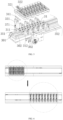
FIG. 3 is a stereoscopic view of a synchronous spacing-changing conveyor device; -
FIG. 4 is a front view of a synchronous spacing-changing conveyor device; -
FIG. 5 is an exploded view of a synchronous spacing-changing conveyor device; -
FIG. 6 illustrates a spacing changing process of a synchronous spacing-changing conveyor device (a top view); -
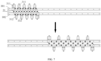
FIG. 7 illustrates a spacing changing process of a synchronous spacing-changing conveyor device (an internal structure); -
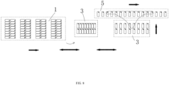
FIG. 8 illustrates a process of blisters from a blister packaging machine to a synchronous spacing-changing conveyor device and then to a cartoning machine; -
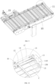
FIG. 9 is a stereoscopic view of a discharging grid conveyor device; and -
FIG. 10 is a partial enlarged view of A inFIG. 9 . - As shown in
FIG. 1 and FIG. 2 , a blister cartoning integrated machine includes a blister packaging machine and a cartoning machine. The blister packaging machine includes discharginggrid conveyor device 1. The blister packaging machine packages articles (such as prefilled syringes, penicillin bottles, and ampoule bottles) into blisters, and then conveys the blisters out through the discharginggrid conveyor device 1. - The cartoning machine includes feeding
grid conveyor device 5. Packaged blisters are placed onto the feedinggrid conveyor device 5, and conveyed by the feedinggrid conveyor device 5 to a cartoning station of the cartoning machine for cartoning (carton packaging). The discharginggrid conveyor device 1 has a different grid spacing from the feeding grid conveyor device. For the sake of matching between the two devices, synchronous spacing-changingconveyor device 3 is provided in front of the discharginggrid conveyor device 1. The synchronous spacing-changingconveyor device 3 is provided side by side with the feedinggrid conveyor device 5. Blisterdischarging transfer manipulator 2 for transferring blisters on the discharginggrid conveyor device 1 to the synchronous spacing-changingconveyor device 3 is provided above the discharginggrid conveyor device 1. The blisterdischarging transfer manipulator 2 includes dischargingvacuum nozzle 20. Blisterfeeding transfer manipulator 4 for transferring blisters on the synchronous spacing-changingconveyor device 3 to the feedinggrid conveyor device 5 is provided above the feedinggrid conveyor device 5. The blisterfeeding transfer manipulator 4 includesfeeding vacuum nozzle 40. - The blister cartoning integrated machine has the following working principle: Blisters are conveyed out from the discharging
grid conveyor device 1 of the blister packaging machine. The blisterdischarging transfer manipulator 2 sucks the blisters on the discharginggrid conveyor device 1 through thedischarging vacuum nozzle 20, and transfers them to the synchronous spacing-changingconveyor device 3. While moving forward, the synchronous spacing-changingconveyor device 3 changes a spacing between the blisters (as shown inFIG. 6 ), until the spacing is the same as the spacing of the feedinggrid conveyor device 5. The blisterfeeding transfer manipulator 4 sucks the blisters on the synchronous spacing-changingconveyor device 3 through thefeeding vacuum nozzle 40, and transfers them to the feedinggrid conveyor device 5. The feedinggrid conveyor device 5 transfers the blisters to the cartoning station of the cartoning machine for cartoning. With the synchronous spacing-changing conveyor device, the present disclosure can greatly improve the linkage production efficiency between the blister packaging machine and the cartoning machine, and solves the problem of hard matching between blister packaging and cartoning in a specification change. - Both the blister packaging machine and the cartoning machine are the prior art (refer to the patent application No.
201520906465.3 201910076327.X 202120863286.1 - The following descriptions are made to the structure and working principle of the synchronous spacing-changing
conveyor device 3. - As shown in
FIG. 3 , the synchronous spacing-changingconveyor device 3 includesbase 30. As shown inFIG. 5 ,first slideway 301 andsecond slideway 302 are provided side by side on thebase 30. A plurality of first slidingseats 311 are slidably provided on thefirst slideway 301. First tray 321 (thefirst tray 321 is provided with a placement groove into which a blister can be placed) is provided on each of the first slidingseats 311. A plurality of second slidingseats 312 are slidably provided on thesecond slideway 302. Second tray 322 (thesecond tray 321 is provided with a placement groove into which a blister can be placed) is provided on each of the second slidingseats 312. The first slidingseat 311 is connected to a hinge shaft. Twocross-connecting rods 31 are hinged crosswise on the hinge shaft. The second slidingseat 312 is also connected to a hinge shaft. Twocross-connecting rods 31 are hinged crosswise on the hinge shaft.Cross-connecting rods 31 on two adjacent first slidingseat 311 and second slidingseat 312 are hinged crosswise in one-to-one correspondence (to form a scissor-type structure). One of the first slidingseats 311 is connected tofirst transmission belt 351. Thefirst transmission belt 351 is in transmission connection withfirst power source 361. One of the second slidingseats 312 is connected tosecond transmission belt 352. As shown inFIG. 4 , thesecond transmission belt 352 is in transmission connection withsecond power source 362. - The synchronous spacing-changing
conveyor device 3 has a following working principle: As shown inFIG. 6 andFIG. 7 , after blisters are placed onto thefirst tray 321 and thesecond tray 322, thefirst power source 361 drives thefirst transmission belt 351 to rotate. Since one of the first slidingseats 311 is connected to thefirst transmission belt 351, the first slidingseats 311 move on thefirst slideway 301. Likewise, thesecond power source 362 drives thesecond transmission belt 352 to rotate. Since one of the second slidingseats 312 is connected to thesecond transmission belt 352, the second slidingseats 312 move on thesecond slideway 302. The first slidingseats 311 are connected to the second slidingseats 312 through thecross-connecting rods 31, so all of the first slidingseats 311 and all of the second slidingseats 312 move. Meanwhile, by adjusting outputs of the power sources, a certain difference is kept between a transfer speed of thefirst transmission belt 351 and a transfer speed of thesecond transmission belt 352, and thus spacings between two adjacent ones of the first slidingseats 311 and the second slidingseats 312 change equidistantly, as shown inFIG. 8 . The blisters have a same spacing as the following feedinggrid conveyor device 5. After the blisters on the trays are taken away, the transmission belts move reversely, and the sliding seats are restored quickly for next receiving. The above process is repeated. With the synchronous spacing-changingconveyor device 3, the discharginggrid conveyor device 1 of the preceding blister packaging machine can be matched with the feedinggrid conveyor device 5 of the following cartoning machine, no matter how the specification of the discharging grid conveyor device changes. - For the blisters of different specifications, different trays are required. For the convenience of replacement of the trays to place the blisters of different specifications, as shown in
FIG. 5 , first supportingseat 331 is provided on the first slidingseat 311. Thefirst tray 321 is provided on the first supportingseat 311. First locatingpin 371 is provided on the first supportingseat 331. A first locating hole for allowing thefirst locating pin 371 to insert into is formed in thefirst tray 321. When thefirst tray 321 is replaced necessarily, thefirst locating pin 371 is pulled out, and thefirst tray 321 is taken down, which is very convenient. Likewise, a second supporting seat is provided on the second slidingseat 312. The second tray is provided on the second supporting seat. A second locating pin is provided on the second supporting seat. A second locating hole for allowing the second locating pin to insert into is formed in the second tray. When the second tray is replaced necessarily, the second locating pin is pulled out, and the second tray is taken down, which is very convenient. - To avoid rotation of the trays, first locating
fixture 341 is provided on the first supportingseat 321. A first locating groove for allowing thefirst locating fixture 341 to enter is formed at a bottom of thefirst tray 321. The first supportingseat 321 is clamped onto thefirst locating fixture 341 through the first locating groove, thereby preventing the rotation of thefirst tray 321. Likewise, the second supporting seat is connected to a second locating fixture. A second locating groove for allowing the second locating fixture to enter is formed at a bottom of thesecond tray 322. Thesecond tray 322 is clamped onto the second locating fixture through the second locating groove, thereby preventing the rotation of thesecond tray 322. - The discharging
grid conveyor device 1 of the blister packaging machine may use a common grid conveyor device. However, the present disclosure provides a novel grid conveyor device. As shown inFIG. 9 and FIG. 10 , the discharginggrid conveyor device 1 includesconveyor rack 10,grid plate 15, first pushingplates 11, a first pushing plate transmission mechanism, and pushingpower source 19. Thegrid plate 15 is provided with feedingchannel 150. The first pushingplates 15 each are provided with pushingportion 110 capable of being located in thefeeding channel 150. The first pushing plate transmission mechanism includesfirst conveyor belt 13. The first pushingplates 11 are connected to thefirst conveyor belt 13. Thefirst conveyor belt 13 is in transmission connection with the pushingpower source 19. During operation, trimmed blisters C fall into the feedingchannel 150 of thegrid plate 15. The pushingpower source 19 drives thefirst conveyor belt 13 to move. Since the first pushingplates 11 are connected to thefirst conveyor belt 13, thefirst conveyor belt 13 drives the first pushingplates 11 to move, and the pushingportions 110 of the first pushingplates 11 push the blisters C to move forward. - For the blisters of different specifications, the grid spacing of the discharging
grid conveyor device 1 can also be adjusted as required, so as to realize a most efficient output. The discharginggrid conveyor device 1 in the present disclosure further includes second pushingplates 12 and a second pushing plate transmission mechanism. The second pushingplates 12 and the first pushingplates 11 are arranged at intervals. The second pushingplates 12 each are provided with a pushing portion located in thefeeding channel 150. The second pushing plate transmission mechanism includessecond conveyor belt 14. Thesecond conveyor belt 14 is provided side by side with thefirst conveyor belt 13. The second pushingplates 12 are connected to thesecond conveyor belt 14. Thesecond conveyor belt 14 is in transmission connection with the pushingpower source 19. The second pushing plate 12 a same pushing principle as the first pushingplate 11, which is not repeated herein. When the grid spacing is adjusted necessarily, either or both of thefirst conveyor belt 13 and thesecond conveyor belt 14 are adjusted to change a spacing between the first pushingplate 11 and the second pushingplate 12, thereby conveying the blisters of the different specifications. - To support the pushing plates, an end of each of the second pushing
plates 12 and the first pushingplates 11 is connected toroller 16.Roller walkway 17 for allowing theroller 16 to walk is provided on theconveyor rack 10. While the pushing plates move, therollers 16 walk on theroller walkway 17 of theconveyor rack 10, thereby supporting the pushing plates and making the pushing plates walk more stably. - Finally, as shown in
FIG. 8 , the dischargingvacuum nozzle 20 of the blister dischargingtransfer manipulator 2 is provided on a rotating power source, such that the blisters from the discharginggrid conveyor device 1 to the synchronous spacing-changingconveyor device 3 are rotated by 90°, and the transverse blisters are placed longitudinally to meet requirements on cartoning positions. With the rotating power source, the dischargingvacuum nozzle 20 is rotated by 90° in movement. The manipulator is rotated when there are many blisters in a longitudinal direction. In case of a small number of blisters in the longitudinal direction, the manipulator is unnecessarily rotated. In addition, the blister feedingtransfer manipulator 4 can track blister suction and placement, such that the synchronous spacing-changingconveyor device 3 and the feedinggrid conveyor device 5 realize continuous conveyance to improve the packaging efficiency.
Claims (9)
- A synchronous spacing-changing conveyor device, comprising a base (30), wherein a first slideway (301) and a second slideway (302) are provided side by side on the base (30); a plurality of first sliding seats (311) are slidably provided on the first slideway (301); a first tray (321) is provided on each of the first sliding seats (311); a plurality of second sliding seats (312) are slidably provided on the second slideway (302); a second tray (322) is provided on each of the second sliding seats (312); one of the first sliding seats (311) is connected to a first transmission belt (351); the first transmission belt (351) is in transmission connection with a first power source (361); one of the second sliding seats (312) is connected to a second transmission belt (352); and the second transmission belt (352) is in transmission connection with a second power source (362); characterized in that the first sliding seat (311) is connected to a first hinge shaft with a rotation axis provided on the first sliding seat (311); two cross-connecting rods (31) are hinged crosswise on the first hinge shaft; the second sliding seat (312) is connected to a second hinge shaft with a rotation axis provided on the second sliding seat (312); two cross-connecting rods (31) are hinged crosswise on the second hinge shaft; cross-connecting rods (31) on two adjacent first sliding seat (311) and second sliding seat (312) are hinged crosswise in one-to-one correspondence.
- The synchronous spacing-changing conveyor device according to claim 1, wherein a first supporting seat (331) is provided on the first sliding seat (311); the first tray (321) is provided on the first supporting seat (331); a first locating pin (371) is provided on the first supporting seat (331); a first locating hole for allowing the first locating pin (371) to insert into is formed in the first tray (321); a second supporting seat is provided on the second sliding seat (312); the second tray is provided on the second supporting seat; a second locating pin is provided on the second supporting seat; and a second locating hole for allowing the second locating pin to insert into is formed in the second tray.
- The synchronous spacing-changing conveyor device according to claim 2, wherein a first locating fixture (341) is provided on the first supporting seat (331); a first locating groove for allowing the first locating fixture (341) to enter is formed at a bottom of the first tray (321); a second locating fixture is provided on the second supporting seat; and a second locating groove for allowing the second locating fixture to enter is formed at a bottom of the second tray.
- A blister cartoning integrated machine, comprising a blister packaging machine and a cartoning machine, wherein the blister packaging machine comprises a discharging grid conveyor device (1) for conveying packaged blisters out through the discharging grid conveyor device (1); the synchronous spacing-changing conveyor device (3) according to any one of claims 1 to 3 is provided in front of the discharging grid conveyor device (1); a blister discharging transfer manipulator (2) for transferring blisters on the discharging grid conveyor device (1) to the synchronous spacing-changing conveyor device (3) is provided above the discharging grid conveyor device (1); the blister discharging transfer manipulator (2) comprises a discharging vacuum nozzle (20); the cartoning machine comprises a feeding grid conveyor device (5) for transferring packaged blisters from the synchronous spacing-changing conveyor device (3) to the cartoning station of the cartoning machine for cartoning; the synchronous spacing-changing conveyor device (3) is provided side by side with the feeding grid conveyor device (5); a blister feeding transfer manipulator (4) for transferring blisters on the synchronous spacing-changing conveyor device (3) to the feeding grid conveyor device (5) is provided above the feeding grid conveyor device (5); and the blister feeding transfer manipulator (4) comprises a feeding vacuum nozzle (40).
- The blister cartoning integrated machine according to claim 4, wherein the discharging grid conveyor device (1) comprises a conveyor rack (10), a grid plate (15), first pushing plates (11), a first pushing plate transmission mechanism, and a pushing power source (19); the grid plate (15) is provided with a feeding channel (150); the first pushing plates (11) each are provided with a pushing portion (110) capable of being located in the feeding channel (150); the first pushing plate transmission mechanism comprises a first conveyor belt (13); the first pushing plates (11) are connected to the first conveyor belt (13); and the first conveyor belt (13) is in transmission connection with the pushing power source (19), such that during operation blisters (C) fall into the feeding channel (150) of the grid plate (15), the pushing power source (19) is configured to drive the first conveyor belt (13) to move, the first conveyor belt (13) is configured to drive the first pushing plates (11) to move, and the pushing portions (110) of the first pushing plates (11) are configured to push the blisters (C) in the feeding channel (150) of the grid plate (15) to move forward.
- The blister cartoning integrated machine according to claim 5, wherein the discharging grid conveyor device (1) comprises second pushing plates (12) and a second pushing plate transmission mechanism; the second pushing plates (12) and the first pushing plates (11) are arranged at intervals; the second pushing plates (12) each are provided with a pushing portion capable of being located in the feeding channel (150); the second pushing plate transmission mechanism comprises a second conveyor belt (14); the second conveyor belt (14) is provided side by side with the first conveyor belt (13); the second pushing plates (12) are connected to the second conveyor belt (14); and the second conveyor belt (14) is in transmission connection with the pushing power source (19), such that during operation blisters (C) fall into the feeding channel (150) of the grid plate (15), the pushing power source (19) is configured to drive the second conveyor belt (14) to move, the second conveyor belt (14) is configured to drive the second pushing plates (12) to move, and the pushing portions of the second pushing plates (12) are configured to push the blisters (C) in the feeding channel (150) of the grid plate (15) to move forward.
- The blister cartoning integrated machine according to claim 6, wherein an end of each of the second pushing plates (12) and the first pushing plates (11) is connected to a roller (16), and a roller walkway (17) for allowing the roller (16) to move is provided on the conveyor rack (10), such that the rollers (16) are configured to move on the roller walkway (17) while the pushing plates (11, 12) move.
- The blister cartoning integrated machine according to claim 4, wherein the discharging vacuum nozzle (20) of the blister discharging transfer manipulator (2) is provided on a rotating power source.
- The blister cartoning integrated machine according to claim 4, wherein the blister feeding transfer manipulator (4) is configured to track blister suction and placement for realizing continuous conveyance between the synchronous spacing-changing conveyor device (3) and the feeding grid conveyor device (5).
Applications Claiming Priority (2)
| Application Number | Priority Date | Filing Date | Title |
|---|---|---|---|
| CN202210186906.1A CN114516449A (en) | 2022-02-28 | 2022-02-28 | Synchronous variable-pitch conveying device and bubble cap and box packaging all-in-one machine applying same |
| PCT/CN2022/109327 WO2023159878A1 (en) | 2022-02-28 | 2022-07-31 | Synchronous variable-pitch conveying device, and blister packaging and boxing integrated machine using same |
Publications (3)
| Publication Number | Publication Date |
|---|---|
| EP4261141A1 EP4261141A1 (en) | 2023-10-18 |
| EP4261141A4 EP4261141A4 (en) | 2024-05-15 |
| EP4261141B1 true EP4261141B1 (en) | 2024-11-27 |
Family
ID=81598704
Family Applications (1)
| Application Number | Title | Priority Date | Filing Date |
|---|---|---|---|
| EP22871103.2A Active EP4261141B1 (en) | 2022-02-28 | 2022-07-31 | Synchronous spacing-changing conveyor device and blister cartoning integrated machine using the same |
Country Status (3)
| Country | Link |
|---|---|
| EP (1) | EP4261141B1 (en) |
| CN (1) | CN114516449A (en) |
| WO (1) | WO2023159878A1 (en) |
Families Citing this family (2)
| Publication number | Priority date | Publication date | Assignee | Title |
|---|---|---|---|---|
| CN114516449A (en) * | 2022-02-28 | 2022-05-20 | 浙江希望机械有限公司 | Synchronous variable-pitch conveying device and bubble cap and box packaging all-in-one machine applying same |
| CN117645032B (en) * | 2024-01-29 | 2024-07-05 | 广东浩普智能设备有限公司 | Linkage shifting plate type auxiliary feeding mechanism |
Family Cites Families (20)
| Publication number | Priority date | Publication date | Assignee | Title |
|---|---|---|---|---|
| IT247454Y1 (en) * | 1999-05-05 | 2002-08-22 | Ima Spa | CONVEYOR FOR THE TRANSPORT OF PACKS, OR STACKS OF PACKS, BLISTERS WITH SAID CONVEYOR EQUIPPED WITH HEIGHT-RECEIVING SEATS |
| US6439631B1 (en) * | 2000-03-03 | 2002-08-27 | Micron Technology, Inc. | Variable-pitch pick and place device |
| DE10340270A1 (en) * | 2003-08-29 | 2005-06-23 | Lieder Maschinenbau Gmbh & Co Kg | Conveying device and method for adaptation |
| CN205837787U (en) * | 2016-07-13 | 2016-12-28 | 常州节卡智能装备有限公司 | Chain cyclic conveyor structure |
| CN106584816B (en) * | 2016-11-25 | 2018-12-21 | 台州市黄岩百星塑料机械厂 | Blower for plastic bottle roller type bottle embryo divides spacing mechanism |
| US11642829B2 (en) * | 2018-06-29 | 2023-05-09 | Nissei Asb Machine Co., Ltd. | Pitch changing device, and molding device provided with same and molding method |
| CN109159145A (en) * | 2018-11-08 | 2019-01-08 | 浙江希望机械有限公司 | A kind of tracking mode bubble cap tray transfer robot arm |
| CN211003513U (en) * | 2019-08-27 | 2020-07-14 | 佛山信涵机器人自动化技术有限公司 | Robot clamp |
| CN211520935U (en) * | 2019-12-25 | 2020-09-18 | 苏州黎鼎智能科技有限公司 | Adjustable equal-division pitch-changing mechanism |
| CN111017303B (en) * | 2019-12-26 | 2025-03-04 | 浙江希望机械有限公司 | Blister Cartoning Machine Pushing Device |
| CN111114907B (en) * | 2020-01-18 | 2025-02-18 | 浙江希望机械有限公司 | Material grid conveying device |
| CN111924187B (en) * | 2020-06-24 | 2024-09-17 | 浙江海悦机器人有限公司 | Flexible head mechanism of grabbing for soft bag case packer |
| CN111688963B (en) * | 2020-06-24 | 2024-09-10 | 浙江海悦机器人有限公司 | Soft bag boxing machine |
| CN111824681A (en) * | 2020-07-20 | 2020-10-27 | 合肥柱石科技有限公司 | Conveying device capable of adapting to clamping and conveying of packaging boxes with different sizes |
| CN111776438A (en) * | 2020-08-03 | 2020-10-16 | 广州达意隆包装机械股份有限公司 | A scissor-type spacing adjustment device |
| CN112109966B (en) * | 2020-10-13 | 2024-07-16 | 烟台凯博机械自动化设备有限公司 | Blood taking needle material taking and distance changing device |
| CN214358915U (en) * | 2020-12-23 | 2021-10-08 | 东莞市德镌精密设备有限公司 | Distance adjusting module for pad printing machine |
| CN113023003B (en) * | 2021-05-12 | 2025-02-14 | 浙江海晨机械有限公司 | A fully automatic pre-filled needle packaging production line |
| CN215664348U (en) * | 2021-06-21 | 2022-01-28 | 楚天科技股份有限公司 | Pitch mechanism and bubble cap machine |
| CN114516449A (en) * | 2022-02-28 | 2022-05-20 | 浙江希望机械有限公司 | Synchronous variable-pitch conveying device and bubble cap and box packaging all-in-one machine applying same |
-
2022
- 2022-02-28 CN CN202210186906.1A patent/CN114516449A/en active Pending
- 2022-07-31 WO PCT/CN2022/109327 patent/WO2023159878A1/en not_active Ceased
- 2022-07-31 EP EP22871103.2A patent/EP4261141B1/en active Active
Also Published As
| Publication number | Publication date |
|---|---|
| CN114516449A (en) | 2022-05-20 |
| EP4261141A1 (en) | 2023-10-18 |
| EP4261141A4 (en) | 2024-05-15 |
| WO2023159878A1 (en) | 2023-08-31 |
Similar Documents
| Publication | Publication Date | Title |
|---|---|---|
| US9540127B2 (en) | Drive mechanism and methods of grouping articles | |
| EP4261141A1 (en) | Synchronous variable-pitch conveying device, and blister packaging and boxing integrated machine using same | |
| KR20100126435A (en) | Goods handling systems | |
| US20160362254A1 (en) | Systems, apparatus, and methods for grouping articles into arrays of various configurations | |
| US9580253B2 (en) | Adjustable carriage for transporting articles of various sizes and a grouping apparatus comprising the same | |
| US3721330A (en) | Article timing and feeding mechanism | |
| CN213036168U (en) | Adjustable conveying belt for boxing machine | |
| CN113023003A (en) | Full-automatic pre-filling needle packaging production line | |
| EP4261142B1 (en) | High-speed blister cartoning integrated machine | |
| CN112752722A (en) | Device and method for conveying products | |
| ITBO20060194A1 (en) | APPARATUS FOR FORMING A CONTINUOUS AND FALLED FLOW OF PAPER ROLLS GROUPS AND OTHER PRODUCTS APPROPRIATELY ORIENTED, INITALLY SINGLE OR PRE-PACKAGED, TOWARDS A CONTINUOUS AND HIGH-PRODUCTION OPERATING MACHINE, SUCH AS A BAGER | |
| CN207226476U (en) | A kind of new efficient feeding system | |
| JP6109509B2 (en) | Article alignment supply device | |
| CN109019022B (en) | Glass feeding and discharging device and method | |
| CN214649323U (en) | Bubble cap plate transfer device | |
| CN219821883U (en) | Continuous feeding and distributing device | |
| JP6826905B2 (en) | Transport device and transport method | |
| CN213109915U (en) | Egg product arraying and outputting device of egg loading and supporting machine | |
| AU2011363537A1 (en) | Apparatus, method of operation of same and tools for use with apparatus | |
| CN201520417U (en) | Servo blanking device and packaging equipment | |
| CN223645113U (en) | An automatic cartoning machine for injection production | |
| CN221050927U (en) | Material handling device and production line with same | |
| JP2020100480A (en) | Integrated device and integrated method | |
| CN221776149U (en) | A fully automatic packing device for plastic bottles | |
| CN222274086U (en) | Filling equipment is used in electronic fluoride liquid production and processing |
Legal Events
| Date | Code | Title | Description |
|---|---|---|---|
| STAA | Information on the status of an ep patent application or granted ep patent |
Free format text: STATUS: UNKNOWN |
|
| STAA | Information on the status of an ep patent application or granted ep patent |
Free format text: STATUS: THE INTERNATIONAL PUBLICATION HAS BEEN MADE |
|
| PUAI | Public reference made under article 153(3) epc to a published international application that has entered the european phase |
Free format text: ORIGINAL CODE: 0009012 |
|
| STAA | Information on the status of an ep patent application or granted ep patent |
Free format text: STATUS: REQUEST FOR EXAMINATION WAS MADE |
|
| 17P | Request for examination filed |
Effective date: 20230330 |
|
| AK | Designated contracting states |
Kind code of ref document: A1 Designated state(s): AL AT BE BG CH CY CZ DE DK EE ES FI FR GB GR HR HU IE IS IT LI LT LU LV MC MK MT NL NO PL PT RO RS SE SI SK SM TR |
|
| A4 | Supplementary search report drawn up and despatched |
Effective date: 20240415 |
|
| RIC1 | Information provided on ipc code assigned before grant |
Ipc: B65B 5/06 20060101ALI20240409BHEP Ipc: B65G 47/52 20060101ALI20240409BHEP Ipc: B65G 47/32 20060101ALI20240409BHEP Ipc: B65B 65/02 20060101ALI20240409BHEP Ipc: B65G 47/26 20060101ALI20240409BHEP Ipc: B65B 59/00 20060101ALI20240409BHEP Ipc: B65B 35/44 20060101ALI20240409BHEP Ipc: B65B 35/38 20060101AFI20240409BHEP |
|
| GRAP | Despatch of communication of intention to grant a patent |
Free format text: ORIGINAL CODE: EPIDOSNIGR1 |
|
| STAA | Information on the status of an ep patent application or granted ep patent |
Free format text: STATUS: GRANT OF PATENT IS INTENDED |
|
| DAV | Request for validation of the european patent (deleted) | ||
| DAX | Request for extension of the european patent (deleted) | ||
| INTG | Intention to grant announced |
Effective date: 20240906 |
|
| GRAS | Grant fee paid |
Free format text: ORIGINAL CODE: EPIDOSNIGR3 |
|
| GRAA | (expected) grant |
Free format text: ORIGINAL CODE: 0009210 |
|
| STAA | Information on the status of an ep patent application or granted ep patent |
Free format text: STATUS: THE PATENT HAS BEEN GRANTED |
|
| AK | Designated contracting states |
Kind code of ref document: B1 Designated state(s): AL AT BE BG CH CY CZ DE DK EE ES FI FR GB GR HR HU IE IS IT LI LT LU LV MC MK MT NL NO PL PT RO RS SE SI SK SM TR |
|
| P01 | Opt-out of the competence of the unified patent court (upc) registered |
Free format text: CASE NUMBER: APP_57503/2024 Effective date: 20241022 |
|
| REG | Reference to a national code |
Ref country code: GB Ref legal event code: FG4D |
|
| REG | Reference to a national code |
Ref country code: CH Ref legal event code: EP |
|
| REG | Reference to a national code |
Ref country code: IE Ref legal event code: FG4D |
|
| REG | Reference to a national code |
Ref country code: DE Ref legal event code: R096 Ref document number: 602022008252 Country of ref document: DE |
|
| REG | Reference to a national code |
Ref country code: LT Ref legal event code: MG9D |
|
| REG | Reference to a national code |
Ref country code: NL Ref legal event code: MP Effective date: 20241127 |
|
| PG25 | Lapsed in a contracting state [announced via postgrant information from national office to epo] |
Ref country code: IS Free format text: LAPSE BECAUSE OF FAILURE TO SUBMIT A TRANSLATION OF THE DESCRIPTION OR TO PAY THE FEE WITHIN THE PRESCRIBED TIME-LIMIT Effective date: 20250327 Ref country code: PT Free format text: LAPSE BECAUSE OF FAILURE TO SUBMIT A TRANSLATION OF THE DESCRIPTION OR TO PAY THE FEE WITHIN THE PRESCRIBED TIME-LIMIT Effective date: 20250327 Ref country code: HR Free format text: LAPSE BECAUSE OF FAILURE TO SUBMIT A TRANSLATION OF THE DESCRIPTION OR TO PAY THE FEE WITHIN THE PRESCRIBED TIME-LIMIT Effective date: 20241127 |
|
| PG25 | Lapsed in a contracting state [announced via postgrant information from national office to epo] |
Ref country code: FI Free format text: LAPSE BECAUSE OF FAILURE TO SUBMIT A TRANSLATION OF THE DESCRIPTION OR TO PAY THE FEE WITHIN THE PRESCRIBED TIME-LIMIT Effective date: 20241127 Ref country code: NL Free format text: LAPSE BECAUSE OF FAILURE TO SUBMIT A TRANSLATION OF THE DESCRIPTION OR TO PAY THE FEE WITHIN THE PRESCRIBED TIME-LIMIT Effective date: 20241127 |
|
| REG | Reference to a national code |
Ref country code: AT Ref legal event code: MK05 Ref document number: 1745510 Country of ref document: AT Kind code of ref document: T Effective date: 20241127 |
|
| PG25 | Lapsed in a contracting state [announced via postgrant information from national office to epo] |
Ref country code: BG Free format text: LAPSE BECAUSE OF FAILURE TO SUBMIT A TRANSLATION OF THE DESCRIPTION OR TO PAY THE FEE WITHIN THE PRESCRIBED TIME-LIMIT Effective date: 20241127 |
|
| PG25 | Lapsed in a contracting state [announced via postgrant information from national office to epo] |
Ref country code: ES Free format text: LAPSE BECAUSE OF FAILURE TO SUBMIT A TRANSLATION OF THE DESCRIPTION OR TO PAY THE FEE WITHIN THE PRESCRIBED TIME-LIMIT Effective date: 20241127 |
|
| PG25 | Lapsed in a contracting state [announced via postgrant information from national office to epo] |
Ref country code: NO Free format text: LAPSE BECAUSE OF FAILURE TO SUBMIT A TRANSLATION OF THE DESCRIPTION OR TO PAY THE FEE WITHIN THE PRESCRIBED TIME-LIMIT Effective date: 20250227 |
|
| PG25 | Lapsed in a contracting state [announced via postgrant information from national office to epo] |
Ref country code: AT Free format text: LAPSE BECAUSE OF FAILURE TO SUBMIT A TRANSLATION OF THE DESCRIPTION OR TO PAY THE FEE WITHIN THE PRESCRIBED TIME-LIMIT Effective date: 20241127 Ref country code: LV Free format text: LAPSE BECAUSE OF FAILURE TO SUBMIT A TRANSLATION OF THE DESCRIPTION OR TO PAY THE FEE WITHIN THE PRESCRIBED TIME-LIMIT Effective date: 20241127 Ref country code: GR Free format text: LAPSE BECAUSE OF FAILURE TO SUBMIT A TRANSLATION OF THE DESCRIPTION OR TO PAY THE FEE WITHIN THE PRESCRIBED TIME-LIMIT Effective date: 20250228 |
|
| PG25 | Lapsed in a contracting state [announced via postgrant information from national office to epo] |
Ref country code: PL Free format text: LAPSE BECAUSE OF FAILURE TO SUBMIT A TRANSLATION OF THE DESCRIPTION OR TO PAY THE FEE WITHIN THE PRESCRIBED TIME-LIMIT Effective date: 20241127 |
|
| PG25 | Lapsed in a contracting state [announced via postgrant information from national office to epo] |
Ref country code: RS Free format text: LAPSE BECAUSE OF FAILURE TO SUBMIT A TRANSLATION OF THE DESCRIPTION OR TO PAY THE FEE WITHIN THE PRESCRIBED TIME-LIMIT Effective date: 20250227 |
|
| PG25 | Lapsed in a contracting state [announced via postgrant information from national office to epo] |
Ref country code: SM Free format text: LAPSE BECAUSE OF FAILURE TO SUBMIT A TRANSLATION OF THE DESCRIPTION OR TO PAY THE FEE WITHIN THE PRESCRIBED TIME-LIMIT Effective date: 20241127 |
|
| PG25 | Lapsed in a contracting state [announced via postgrant information from national office to epo] |
Ref country code: DK Free format text: LAPSE BECAUSE OF FAILURE TO SUBMIT A TRANSLATION OF THE DESCRIPTION OR TO PAY THE FEE WITHIN THE PRESCRIBED TIME-LIMIT Effective date: 20241127 |
|
| PG25 | Lapsed in a contracting state [announced via postgrant information from national office to epo] |
Ref country code: EE Free format text: LAPSE BECAUSE OF FAILURE TO SUBMIT A TRANSLATION OF THE DESCRIPTION OR TO PAY THE FEE WITHIN THE PRESCRIBED TIME-LIMIT Effective date: 20241127 |
|
| PG25 | Lapsed in a contracting state [announced via postgrant information from national office to epo] |
Ref country code: RO Free format text: LAPSE BECAUSE OF FAILURE TO SUBMIT A TRANSLATION OF THE DESCRIPTION OR TO PAY THE FEE WITHIN THE PRESCRIBED TIME-LIMIT Effective date: 20241127 |
|
| PG25 | Lapsed in a contracting state [announced via postgrant information from national office to epo] |
Ref country code: SK Free format text: LAPSE BECAUSE OF FAILURE TO SUBMIT A TRANSLATION OF THE DESCRIPTION OR TO PAY THE FEE WITHIN THE PRESCRIBED TIME-LIMIT Effective date: 20241127 |
|
| PG25 | Lapsed in a contracting state [announced via postgrant information from national office to epo] |
Ref country code: CZ Free format text: LAPSE BECAUSE OF FAILURE TO SUBMIT A TRANSLATION OF THE DESCRIPTION OR TO PAY THE FEE WITHIN THE PRESCRIBED TIME-LIMIT Effective date: 20241127 |
|
| REG | Reference to a national code |
Ref country code: DE Ref legal event code: R097 Ref document number: 602022008252 Country of ref document: DE |
|
| PG25 | Lapsed in a contracting state [announced via postgrant information from national office to epo] |
Ref country code: SE Free format text: LAPSE BECAUSE OF FAILURE TO SUBMIT A TRANSLATION OF THE DESCRIPTION OR TO PAY THE FEE WITHIN THE PRESCRIBED TIME-LIMIT Effective date: 20241127 |
|
| PLBE | No opposition filed within time limit |
Free format text: ORIGINAL CODE: 0009261 |
|
| STAA | Information on the status of an ep patent application or granted ep patent |
Free format text: STATUS: NO OPPOSITION FILED WITHIN TIME LIMIT |
|
| REG | Reference to a national code |
Ref country code: CH Ref legal event code: L10 Free format text: ST27 STATUS EVENT CODE: U-0-0-L10-L00 (AS PROVIDED BY THE NATIONAL OFFICE) Effective date: 20251008 |
|
| PGFP | Annual fee paid to national office [announced via postgrant information from national office to epo] |
Ref country code: DE Payment date: 20250627 Year of fee payment: 4 |
|
| PGFP | Annual fee paid to national office [announced via postgrant information from national office to epo] |
Ref country code: IT Payment date: 20250731 Year of fee payment: 4 |
|
| 26N | No opposition filed |
Effective date: 20250828 |
|
| REG | Reference to a national code |
Ref country code: CH Ref legal event code: H13 Free format text: ST27 STATUS EVENT CODE: U-0-0-H10-H13 (AS PROVIDED BY THE NATIONAL OFFICE) Effective date: 20260224 |
|
| PG25 | Lapsed in a contracting state [announced via postgrant information from national office to epo] |
Ref country code: LU Free format text: LAPSE BECAUSE OF NON-PAYMENT OF DUE FEES Effective date: 20250731 |
|
| REG | Reference to a national code |
Ref country code: BE Ref legal event code: MM Effective date: 20250731 |
|
| PG25 | Lapsed in a contracting state [announced via postgrant information from national office to epo] |
Ref country code: BE Free format text: LAPSE BECAUSE OF NON-PAYMENT OF DUE FEES Effective date: 20250731 |
|
| PG25 | Lapsed in a contracting state [announced via postgrant information from national office to epo] |
Ref country code: FR Free format text: LAPSE BECAUSE OF NON-PAYMENT OF DUE FEES Effective date: 20250731 |
|
| PG25 | Lapsed in a contracting state [announced via postgrant information from national office to epo] |
Ref country code: CH Free format text: LAPSE BECAUSE OF NON-PAYMENT OF DUE FEES Effective date: 20250731 |