EP4261071A1 - Display arrangement for video workstation in a vehicle - Google Patents
Display arrangement for video workstation in a vehicle Download PDFInfo
- Publication number
- EP4261071A1 EP4261071A1 EP22382356.8A EP22382356A EP4261071A1 EP 4261071 A1 EP4261071 A1 EP 4261071A1 EP 22382356 A EP22382356 A EP 22382356A EP 4261071 A1 EP4261071 A1 EP 4261071A1
- Authority
- EP
- European Patent Office
- Prior art keywords
- video data
- vehicle
- operator
- movement
- display unit
- Prior art date
- Legal status (The legal status is an assumption and is not a legal conclusion. Google has not performed a legal analysis and makes no representation as to the accuracy of the status listed.)
- Pending
Links
- 230000002093 peripheral effect Effects 0.000 claims description 9
- 230000001720 vestibular Effects 0.000 abstract description 23
- 238000013459 approach Methods 0.000 abstract description 5
- 230000001953 sensory effect Effects 0.000 abstract description 4
- 230000000007 visual effect Effects 0.000 description 35
- 210000003128 head Anatomy 0.000 description 15
- 206010025482 malaise Diseases 0.000 description 14
- 230000003068 static effect Effects 0.000 description 10
- 230000008447 perception Effects 0.000 description 4
- 238000005259 measurement Methods 0.000 description 3
- 230000006870 function Effects 0.000 description 2
- 238000012552 review Methods 0.000 description 2
- 230000016776 visual perception Effects 0.000 description 2
- 230000008859 change Effects 0.000 description 1
- 230000001419 dependent effect Effects 0.000 description 1
- 238000011161 development Methods 0.000 description 1
- 230000018109 developmental process Effects 0.000 description 1
- 230000000694 effects Effects 0.000 description 1
- 230000001788 irregular Effects 0.000 description 1
- 238000000034 method Methods 0.000 description 1
- 230000003287 optical effect Effects 0.000 description 1
- 230000008569 process Effects 0.000 description 1
- 230000004044 response Effects 0.000 description 1
- 210000000697 sensory organ Anatomy 0.000 description 1
- 239000007787 solid Substances 0.000 description 1
Images

Classifications
-
- B—PERFORMING OPERATIONS; TRANSPORTING
- B60—VEHICLES IN GENERAL
- B60K—ARRANGEMENT OR MOUNTING OF PROPULSION UNITS OR OF TRANSMISSIONS IN VEHICLES; ARRANGEMENT OR MOUNTING OF PLURAL DIVERSE PRIME-MOVERS IN VEHICLES; AUXILIARY DRIVES FOR VEHICLES; INSTRUMENTATION OR DASHBOARDS FOR VEHICLES; ARRANGEMENTS IN CONNECTION WITH COOLING, AIR INTAKE, GAS EXHAUST OR FUEL SUPPLY OF PROPULSION UNITS IN VEHICLES
- B60K35/00—Instruments specially adapted for vehicles; Arrangement of instruments in or on vehicles
- B60K35/10—Input arrangements, i.e. from user to vehicle, associated with vehicle functions or specially adapted therefor
-
- B—PERFORMING OPERATIONS; TRANSPORTING
- B60—VEHICLES IN GENERAL
- B60K—ARRANGEMENT OR MOUNTING OF PROPULSION UNITS OR OF TRANSMISSIONS IN VEHICLES; ARRANGEMENT OR MOUNTING OF PLURAL DIVERSE PRIME-MOVERS IN VEHICLES; AUXILIARY DRIVES FOR VEHICLES; INSTRUMENTATION OR DASHBOARDS FOR VEHICLES; ARRANGEMENTS IN CONNECTION WITH COOLING, AIR INTAKE, GAS EXHAUST OR FUEL SUPPLY OF PROPULSION UNITS IN VEHICLES
- B60K35/00—Instruments specially adapted for vehicles; Arrangement of instruments in or on vehicles
- B60K35/20—Output arrangements, i.e. from vehicle to user, associated with vehicle functions or specially adapted therefor
- B60K35/28—Output arrangements, i.e. from vehicle to user, associated with vehicle functions or specially adapted therefor characterised by the type of the output information, e.g. video entertainment or vehicle dynamics information; characterised by the purpose of the output information, e.g. for attracting the attention of the driver
-
- G—PHYSICS
- G02—OPTICS
- G02B—OPTICAL ELEMENTS, SYSTEMS OR APPARATUS
- G02B27/00—Optical systems or apparatus not provided for by any of the groups G02B1/00 - G02B26/00, G02B30/00
- G02B27/01—Head-up displays
- G02B27/017—Head mounted
-
- G—PHYSICS
- G06—COMPUTING; CALCULATING OR COUNTING
- G06F—ELECTRIC DIGITAL DATA PROCESSING
- G06F3/00—Input arrangements for transferring data to be processed into a form capable of being handled by the computer; Output arrangements for transferring data from processing unit to output unit, e.g. interface arrangements
- G06F3/01—Input arrangements or combined input and output arrangements for interaction between user and computer
- G06F3/011—Arrangements for interaction with the human body, e.g. for user immersion in virtual reality
- G06F3/012—Head tracking input arrangements
-
- B—PERFORMING OPERATIONS; TRANSPORTING
- B60—VEHICLES IN GENERAL
- B60K—ARRANGEMENT OR MOUNTING OF PROPULSION UNITS OR OF TRANSMISSIONS IN VEHICLES; ARRANGEMENT OR MOUNTING OF PLURAL DIVERSE PRIME-MOVERS IN VEHICLES; AUXILIARY DRIVES FOR VEHICLES; INSTRUMENTATION OR DASHBOARDS FOR VEHICLES; ARRANGEMENTS IN CONNECTION WITH COOLING, AIR INTAKE, GAS EXHAUST OR FUEL SUPPLY OF PROPULSION UNITS IN VEHICLES
- B60K2360/00—Indexing scheme associated with groups B60K35/00 or B60K37/00 relating to details of instruments or dashboards
- B60K2360/16—Type of output information
- B60K2360/165—Videos and animations
-
- B—PERFORMING OPERATIONS; TRANSPORTING
- B60—VEHICLES IN GENERAL
- B60K—ARRANGEMENT OR MOUNTING OF PROPULSION UNITS OR OF TRANSMISSIONS IN VEHICLES; ARRANGEMENT OR MOUNTING OF PLURAL DIVERSE PRIME-MOVERS IN VEHICLES; AUXILIARY DRIVES FOR VEHICLES; INSTRUMENTATION OR DASHBOARDS FOR VEHICLES; ARRANGEMENTS IN CONNECTION WITH COOLING, AIR INTAKE, GAS EXHAUST OR FUEL SUPPLY OF PROPULSION UNITS IN VEHICLES
- B60K2360/00—Indexing scheme associated with groups B60K35/00 or B60K37/00 relating to details of instruments or dashboards
- B60K2360/16—Type of output information
- B60K2360/177—Augmented reality
-
- G—PHYSICS
- G02—OPTICS
- G02B—OPTICAL ELEMENTS, SYSTEMS OR APPARATUS
- G02B27/00—Optical systems or apparatus not provided for by any of the groups G02B1/00 - G02B26/00, G02B30/00
- G02B27/01—Head-up displays
- G02B27/0101—Head-up displays characterised by optical features
- G02B2027/0138—Head-up displays characterised by optical features comprising image capture systems, e.g. camera
-
- G—PHYSICS
- G02—OPTICS
- G02B—OPTICAL ELEMENTS, SYSTEMS OR APPARATUS
- G02B27/00—Optical systems or apparatus not provided for by any of the groups G02B1/00 - G02B26/00, G02B30/00
- G02B27/01—Head-up displays
- G02B27/0101—Head-up displays characterised by optical features
- G02B2027/014—Head-up displays characterised by optical features comprising information/image processing systems
-
- G—PHYSICS
- G02—OPTICS
- G02B—OPTICAL ELEMENTS, SYSTEMS OR APPARATUS
- G02B27/00—Optical systems or apparatus not provided for by any of the groups G02B1/00 - G02B26/00, G02B30/00
- G02B27/01—Head-up displays
- G02B27/0179—Display position adjusting means not related to the information to be displayed
- G02B2027/0187—Display position adjusting means not related to the information to be displayed slaved to motion of at least a part of the body of the user, e.g. head, eye
-
- G—PHYSICS
- G09—EDUCATION; CRYPTOGRAPHY; DISPLAY; ADVERTISING; SEALS
- G09G—ARRANGEMENTS OR CIRCUITS FOR CONTROL OF INDICATING DEVICES USING STATIC MEANS TO PRESENT VARIABLE INFORMATION
- G09G2320/00—Control of display operating conditions
- G09G2320/02—Improving the quality of display appearance
- G09G2320/0261—Improving the quality of display appearance in the context of movement of objects on the screen or movement of the observer relative to the screen
-
- G—PHYSICS
- G09—EDUCATION; CRYPTOGRAPHY; DISPLAY; ADVERTISING; SEALS
- G09G—ARRANGEMENTS OR CIRCUITS FOR CONTROL OF INDICATING DEVICES USING STATIC MEANS TO PRESENT VARIABLE INFORMATION
- G09G2320/00—Control of display operating conditions
- G09G2320/06—Adjustment of display parameters
- G09G2320/068—Adjustment of display parameters for control of viewing angle adjustment
-
- G—PHYSICS
- G09—EDUCATION; CRYPTOGRAPHY; DISPLAY; ADVERTISING; SEALS
- G09G—ARRANGEMENTS OR CIRCUITS FOR CONTROL OF INDICATING DEVICES USING STATIC MEANS TO PRESENT VARIABLE INFORMATION
- G09G2340/00—Aspects of display data processing
- G09G2340/10—Mixing of images, i.e. displayed pixel being the result of an operation, e.g. adding, on the corresponding input pixels
-
- G—PHYSICS
- G09—EDUCATION; CRYPTOGRAPHY; DISPLAY; ADVERTISING; SEALS
- G09G—ARRANGEMENTS OR CIRCUITS FOR CONTROL OF INDICATING DEVICES USING STATIC MEANS TO PRESENT VARIABLE INFORMATION
- G09G2340/00—Aspects of display data processing
- G09G2340/12—Overlay of images, i.e. displayed pixel being the result of switching between the corresponding input pixels
-
- G—PHYSICS
- G09—EDUCATION; CRYPTOGRAPHY; DISPLAY; ADVERTISING; SEALS
- G09G—ARRANGEMENTS OR CIRCUITS FOR CONTROL OF INDICATING DEVICES USING STATIC MEANS TO PRESENT VARIABLE INFORMATION
- G09G2354/00—Aspects of interface with display user
-
- G—PHYSICS
- G09—EDUCATION; CRYPTOGRAPHY; DISPLAY; ADVERTISING; SEALS
- G09G—ARRANGEMENTS OR CIRCUITS FOR CONTROL OF INDICATING DEVICES USING STATIC MEANS TO PRESENT VARIABLE INFORMATION
- G09G2380/00—Specific applications
- G09G2380/12—Avionics applications
-
- G—PHYSICS
- G09—EDUCATION; CRYPTOGRAPHY; DISPLAY; ADVERTISING; SEALS
- G09G—ARRANGEMENTS OR CIRCUITS FOR CONTROL OF INDICATING DEVICES USING STATIC MEANS TO PRESENT VARIABLE INFORMATION
- G09G3/00—Control arrangements or circuits, of interest only in connection with visual indicators other than cathode-ray tubes
- G09G3/001—Control arrangements or circuits, of interest only in connection with visual indicators other than cathode-ray tubes using specific devices not provided for in groups G09G3/02 - G09G3/36, e.g. using an intermediate record carrier such as a film slide; Projection systems; Display of non-alphanumerical information, solely or in combination with alphanumerical information, e.g. digital display on projected diapositive as background
- G09G3/003—Control arrangements or circuits, of interest only in connection with visual indicators other than cathode-ray tubes using specific devices not provided for in groups G09G3/02 - G09G3/36, e.g. using an intermediate record carrier such as a film slide; Projection systems; Display of non-alphanumerical information, solely or in combination with alphanumerical information, e.g. digital display on projected diapositive as background to produce spatial visual effects
Definitions
- the description relates to a display arrangement for presenting a virtual video scenario to a human operator in a vehicle, and to a vehicle with such a display arrangement.
- the display arrangement may be part of a video workstation of an operator and may be located within an aircraft or any other movable vehicle.
- Video workstations for human operators become more and more relevant in modern working environments. Such workstations present video data to the operator and receive input commands from the operator to carry out certain actions. For example, a video workstation may present information to the operator and receive commands for machines that interact with the environment.
- Such video workstations can be used to remotely command machines, industrial plants, military devices, or other devices without the need for an operator to be physically where the commanded devices are.
- a display arrangement for presenting a virtual video scenario to a human operator in a vehicle.
- the display arrangement comprises a display unit with a housing, a first sensor, and a retaining strap.
- the display unit is configured to be releasably attached to a head of the human operator, and the first sensor is configured to sense first spatial movement information of the display unit.
- the display arrangement further comprises a second sensor that is couplable to the vehicle and configured to sense second spatial movement information of the vehicle.
- the display arrangement further comprises a control unit that is communicatively coupled to the display unit and configured to provide a virtual video scenario to be displayed by the display unit, and to receive the first spatial movement information.
- the control unit is communicatively coupled to the second sensor and configured to receive the second spatial movement information.
- the control unit is configured to generate the virtual video scenario based on background video data and application video data.
- the control unit is further configured to determine a relative movement of the display unit with regard to the vehicle based on the second spatial movement information and the first spatial movement information.
- the control unit is further configured to modify the background video data based on the second spatial movement information, and to modify the application video data based on the second spatial movement information and the relative movement of the display unit with regard to the vehicle.
- the display arrangement described herein may be used for a virtual reality based workplace in vehicle like aircraft, land vehicle, watercraft, submarine vessels, or any other movable platforms.
- a workplace may be a workplace inside a search and rescue aircraft or a full immersive helmet mounted display inside an aircraft cockpit.
- the risk of cyber sickness is reduced by the display arrangement described herein because it combines the presentation of video material (application video data which are required to be presented to the operator) with the presentation of visual cues (background video data) representing the vehicle's movement in the real world.
- This approach may mitigate the effects that cause cyber sickness because the operator is presented background video data that is coupled to the vehicle movement and presents visual information to the operator which correspond to the impressions perceived by the vestibular system.
- the virtual video scenario is presented to the operator in such a way that even when the operator focuses on the application video data, there are still enough visual cues in the peripheral view of the operator representing the vehicle movement to keep the stimuli of the vestibular system and the visual system in line.
- the control unit generates and provides the background video data in such a manner that the background video data is coupled to the second spatial movement (movement of the vehicle). It appears to the operator as if the background video data is a static background and the vehicle moves with respect to the static background. For example, the background video data needs to be moved to compensate for the vehicle movement, especially by moving the background video data in the opposite direction to the movement of the vehicle. That is how the vestibular system and the visual system of the operator are held in line with each other and provide corresponding perceptions.
- the background video data does not include any operational data relevant to the working processes of the operator. Instead, the background video data only provides visual cues to the operator so that the visual system perceives sensual impressions that correspond to the impressions of the vestibular system.
- the background video data represents a virtual scenery like a sphere with a diameter much larger than the operator to create an artificial horizon.
- the background video data may include objects located at regular or irregular distances to each other and being shaped same or different with same or different sizes.
- the background video data includes objects that are static on the artificial horizon, i.e., there is preferably no relative movement between the objects of the artificial horizon, and the objects in the background video data only move when the vehicle performs a rotational movement about one of the spatial axes.
- linear movements of the vehicle along one of the spatial axes are not reflected by the background video data, i.e., the objects of the background video data do not come closer or move away from the position of the operator's eye during linear movement of the vehicle.
- Such linear movement may not be required to be represented by the background video data because linear movement may not have any impact on cyber sickness.
- the purpose of the background video data is to provide a visual environment to the operator so that actual movements of the vehicle are represented by movements of the background video data to avoid differences between vestibular and visual perceptions.
- the center of the sphere is bound to the operator's eyes.
- the sphere may include a polar grid to provide appropriate visual cues to the operator.
- the sphere gives the operator the necessary visual impression about the movement of the operator inside the real world and is in line with the impression of the vestibular system.
- the application video data includes the video data that are presented to the operator for carrying out the operator's tasks.
- Application video data can be any data that is required by the operator to perform an assigned task.
- the application video data is embedded or overlays the background video data. However, the application video data does not entirely overlay the background video data. Rather, the application video data takes only a part of the operator's field of view while the peripheral area of the field of view of the operator still includes visual information of the background video data.
- the application video data are moved in the same direction as the vehicle.
- the operator also gets the visual impression of the vehicle's movement with regard to the background.
- the background video data are modified to move opposite to the vehicle's movement and the application video data are modified to move with the vehicle's movement.
- the vestibular system perceives that movement automatically per its inherent functioning, and the visual system of the operator perceives that movement because the application video data are modified to move with respect to the background video data.
- the application video data is modified based on the relative movement of the display unit with regard to the vehicle.
- this movement of the operator's head also results in modifying the perspective onto the application video data.
- the application video data may also relate to static images or images that are static for a limited period of time.
- the background video data is modified and moved in response to movements of the vehicle.
- the background video data is not moved, too.
- this static image as such is nevertheless moved with respect to the background video data when the vehicle performs a movement about one or more spatial axes (this means that a static image as such is movable with respect to the background video data although its content is not moving).
- the movement of the vehicle and the movement of the operator's head are sensed by respective sensors.
- the first sensor senses the movement of the vehicle.
- the first sensor is configured to sense a rotational movement of the vehicle about one, two, or three spatial axes (roll, pitch, yaw), depending on the type of vehicle.
- the movements about all three spatial axes are preferably sensed.
- sensing the rotational movement about the yaw-axis may be sufficient.
- the second sensor senses the movement of the operator or of the operator's head, similar to what is described with reference to the first sensor and the vehicle's movement. However, since the operator is located within the vehicle, the second sensor senses the overall movement of the operator or the operator's head, i.e., the movement of the vehicle superimposed with the movement of the operator or the operator's head. Therefore, in order to identify the movement of the operator or the operator's head relative to the vehicle, the movement of the vehicle needs to be eliminated from the movement sensed by the second sensor.
- the background video data is modified based on the second spatial movement information (movement of the vehicle)
- the relative movement of the application video data with respect to the background video data is determined based on the second spatial movement information (movement of the vehicle)
- the perspective of the operator onto the application video data is determined based on the relative movement of the display unit with regard to the vehicle (movement of the display unit cleared by the movement of the vehicle).
- the virtual video scenario is the video presented to the operator by a display of the display unit.
- the display may be any kind of display that is suitable for being used in head mounted display units.
- This virtual video scenario is composed of background video data and application video data.
- the background video data and the application video data refer to the optical signals than can be visually perceived by the operator.
- the background video data and the application video data are displayed by the display unit and are based on electronic signals that are generated and provided by the control unit.
- the control unit when saying that the control unit generates and provides the background and application video data to the display unit, this means that the control unit generates any commands and signals which are in a predetermined protocol to instruct the display unit to present visually perceivable information to an operator.
- the control unit may be a computer like a general purpose computer with a graphics unit that generates and outputs video data for the display unit.
- the control unit may be programmed in a certain manner to carry out the functions described with reference to the control unit and to instruct the display unit to present the virtual video scenario as described herein.
- the first and second sensors each may be inertial measuring units which are configured to sense rotational movements about one or more spatial axes.
- the first sensor may be attached to the display unit or one of its components, preferably to the housing of the display unit, and is configured detect movements of the operator's head.
- the second sensor may be attached to the vehicle, e.g., to a fuselage of an aircraft or to a frame member of the vehicle, and is configured to detect movements of the vehicle.
- modifying the background video data and/or the application video data may particularly mean that the background and/or application video data are rotated and/or moved on a display presented to an operator to be in line with the movements of the vehicle and/or the head of the operator and/or to compensate any of these movements.
- it is not necessarily the content of the background and/or application video data, but typically only the orientation and position of the background and/or application video data that is modified as described herein.
- the first sensor is configured to sense a rotational movement of the display unit about at least one spatial axis.
- the relevant movements and/or movement changes for cyber sickness as referred to in this document are rotational movements because those cause a conflict between the vestibular system and the visual system of a human operator.
- the first sensor particularly senses rotational movements of the display unit that is coupled to the operator's head.
- the first sensor is configured to sense a rotational movement of the display unit about each of three orthogonal spatial axes.
- the first sensor of this embodiment senses movements of the operator's head about all spatial axes and can, therefore, vary the perspective onto the application data in accordance with any movement of the operator's head.
- the second sensor is configured to sense a rotational movement of the vehicle about at least one spatial axis.
- the second sensor is configured to sense a rotational movement of the vehicle about each of three orthogonal spatial axes.
- This embodiment is particularly useful for aircraft and submarine vessel applications because these vehicles are free to perform movements about all three spatial axes.
- the background video data represent a spherical artificial horizon that surrounds an eye-point of the operator at a predetermined virtual distance.
- the application video data is embedded within the background video data and overlays the background video data when observed by the operator.
- the application video data is surrounded by a peripheral region represented by background video data not overlaid by the application video data.
- control unit is configured to determine the relative movement of the display unit with regard to the vehicle by subtracting the second spatial movement information from the first spatial movement information.
- control unit is configured to modify the background video data based on the second spatial movement information in a manner that the background video data perform a movement opposite to the second spatial movement.
- the background video data represent a static artificial horizon with respect to which the vehicle moves when performing the second spatial movement.
- the vestibular system of the human operator and the visual impression of the background video data correspond to each other.
- the control unit modifies the background video data such that it rotates counterclockwise at the same amount of the angular velocity at which the vehicle rotates clockwise.
- a similar approach relates to the other two spatial axes (roll- and pitch-axis).
- the background video is concurrently moved in the opposite direction so that the sensory impressions of an operator received from the vestibular systems and the visual impressions of the operator's eyes are congruent.
- the control unit generates and modifies the background video data (and the video represented thereby) such that the operator has the visual impression to move with respect to the background video data in correspondence with the actual movement of the vehicle.
- control unit is configured to modify the application video data based on the second spatial movement information in a manner that the application video data perform a movement with respect to the background video data in the same direction as the second spatial movement.
- the control unit generates and modifies the application video data such that the application video presented to the operator performs a relative movement to the background video in such a manner that the movement of the application video with respect to the background video corresponds to the second spatial movement (movement of the vehicle).
- the operator gets the visual impression that the application video moves in a manner that corresponds to the movement of the vehicle while the background video appears static because it moves opposite to the movement of the vehicle.
- This approach allows for resolving possible conflicts between visual impressions and impressions of the vestibular system when a human operator works in a moving vehicle with a head mounted display that isolates the visual impressions from the surroundings.
- control unit is configured to modify the application video data based on the relative movement of the display unit with regard to the vehicle in a manner that the application video data are shown from a different perspective in accordance with the relative movement of the display unit with regard to the vehicle.
- the movement of the display unit with respect to the vehicle in which the operator is located and operates with the display arrangement is used to determine the perspective or viewpoint of the operator onto the application video.
- the relative movement of the display unit with respect to the vehicle is used because it is this relative movement that is relevant for the perspective onto the application video data.
- the background video data are modified so that the background video moves opposite to the vehicle movements.
- the application video data are modified so that the application video moves with respect to the background video in accordance with the vehicle movement.
- a perspective onto the application video can be modified based on the relative movements of the display unit with respect to the vehicle. This approach may reduce conflicts between sensory impressions of the vestibular system and the eyes of the operator because the movements of the vehicle as well as the movements of the display unit are considered when generating and modifying the background and application video data presented to the operator.
- the display arrangement comprises a position tracking unit that is arranged and configured to detect position changes of the display unit with respect to a reference object.
- the position tracking unit may comprise a camera or other sensors that are able to detect the relative position of the display unit with respect to the camera of the other sensors.
- the position of the display unit is then transmitted to the control unit and the control unit is configured to generate and provide the application video data in additional consideration of the position of the display unit.
- the perspective of the operator onto the application video data may be varied in accordance with the position of the display unit.
- the display unit may include markers that are detected by the position tracking unit in order to determine the position of the display unit.
- a vehicle that comprises a display arrangement as described above and hereinafter, wherein the display arrangement is part of a video workstation for an operator.
- the second sensor is fixedly attached to the vehicle.
- the sensor performs the movements of the vehicle
- the control unit is provided with the respective sensor data in order to generate and provide the virtual video scenario as described above with reference to the display arrangement.
- the vehicle is an aircraft.
- the aircraft may include a workplace for an operator who is provided with video data via a head mounted display.
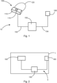
- Fig. 1 shows a display arrangement 10 with a display unit 100, a control unit 150, and a second sensor 160.
- the display unit 100 comprises a housing 110, a first sensor 115 mounted to the housing 110, and a retaining strap 120 attached to the housing 110 and configured to hold the display unit 100 relative to a head of a human operator in front of the operator's eyes so that the operator can visually perceive a virtual video scenario displayed by the display unit 100.
- the control unit 150 is communicatively connected to the display unit 100 via a first data exchange connection 152, and to the second sensor 160 via a second data exchange connection 154.
- the first and second data exchange connections 152, 154 may be wireless or wired connections.
- the control unit 150 provides the video scenario to the display unit 110 for being presented to the operator and receives measurement data sensed by the first sensor 115 relating to rotational movements of the display unit 100 and/or of its housing 110.
- the control unit 150 furthermore receives measurement data sensed by the second sensor 160 relating to rotational movements of the vehicle to which the second sensor 160 is attached.
- control unit 115 Based on the data received from the first and second sensors 115, 160, the control unit 115 generates and provides the video scenario with the background video data and the application video data presented by the display unit 100.
- Fig. 2 shows a vehicle 1 with a video workstation 5 that comprises the components of the display arrangement described with reference to Fig. 1 .
- the video workstation 5 comprises the display unit 100, the control unit 150, and the second sensor 160, which is attached to the vehicle 1.
- the workstation 5 may also include input elements like any known input devices for interacting with a computer, e.g., a keyboard, a mouse, touch-sensitive screens, data gloves, etc.
- the input elements are not shown in Fig. 2 for the sake of simplicity.
- the input elements receive input commands from the operator.
- the control unit 150 performs actions based on the input commands.
- Fig. 3 schematically shows a vehicle 1 and possible rotational movements about the roll-axis 2, and/or the yaw-axis 3, and/or the pitch-axis 4. These rotational movements are the cause for sensory impressions perceived by the vestibular system of an operator located in a vehicle. However, when the visual perceptions do not correspond to the vestibular impressions, this may cause cyber sickness. When the operator wears a head mounted display and is visually decoupled from the environment, the risk for cyber sickness may be high.
- the operator is provided with video data that bring the visual impressions in line with the vestibular impressions, as described with reference to the following Figs.
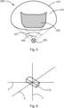
- Fig. 4 schematically shows a virtual video scenario 200 which is composed of background video data 210, application video data 220, and an eye-point 230 of an operator.
- the virtual video scenario 200 is generated by the control unit 150 (see Fig. 1 and 2 ) so that the background video data 210 has a certain distance to the eye-point 230.
- the background video data corresponds to an artificial horizon shaped like a sphere with the radius 235 with the eye-point 230 in the center of that virtual sphere.
- the artificial horizon is spaced apart the same distance from the eye-point 230.
- the background video data 210 serves as a frame for the visual system of the operator within which the physical movements of the vehicle are mapped to bring and/or keep the impressions of the visual and vestibular system in line.
- the video scenario 200 additionally includes a region with application video data 220 which form only a part of the field of view of the operator.
- the application video data do not cover the entire background video data visible to the operator.
- the application video data span over a spatial angle of about 60° while the remainder of the field of view of the operator is background video data.
- the peripheral field of view of the operator visually presents background video data to the operator.
- the display arrangement 10 can provide information about the movement of the aircraft (by the second sensor 160) and about the movement of the display unit 100 (by the first sensor 115).
- the control unit 150 is able to determine the movement of the display unit 100 relative to the aircraft based on the measurement data of both sensors 115, 160.
- the display arrangement 10 provides two different types of visual stimuli to the operator.
- the first one is realized as a sphere, called real world sphere in the following and indicated by reference sign 210, with a diameter or radius 235 much larger than the operator, wherein the sphere surrounds the operator, indicated by eye-point 230.
- the center of the sphere 210 is bound to the position of the operator's eyes, so that the operator's eyes are always in the center of the sphere.
- the sphere represents in its easiest realization an artificial horizon with a polar grid and its orientation is coupled to the vehicle's movement in a way that compensates the vehicle's movement by moving the sphere opposite to the vehicle's movement, so that the sphere seems to be steady to the operator like the operator would expect it from the real world.
- This sphere gives the operator the necessary visual stimuli about the own movement inside the real world which is also in line with his vestibular stimuli.
- an adaptable part of a smaller sphere in the following and indicated by reference sign 220, which is concentric to the real world sphere 210 is used.
- This spherical display segment 220 can in general be of any size and be placed at any direction regarding the normal viewing direction of the operator with the following restriction.
- the spherical display segment 220 is typically steady to the vehicle as well in position as also in size like a real display inside a vehicle.
- the spherical display segment 220 may be resized and repositioned manually by the operator.
- the spherical display segment 220 may serve beside others as visual cue for the movement of the operator relevant to the vehicle.
- an algorithm clips the spherical display segment to a size that enough visual stimuli from the real world sphere 210 are visible in the peripheral view of the operator.
- the same algorithms may also add vehicle steady geometry, if too less of the spherical display segment is visible.
- Fig. 5 shows a schematic view of the perspective of the operator from the eye-point 230.
- the background video data 210 actually span over the entirety of the field of view with a viewing angle 237 that defines the entire field of view.
- the application video data 220 shown at the spherical display segment are visible in a smaller part of the field of view with a viewing angle 239.
- the viewing angles 237 and 239 may be solid angles.
- the viewing angle 237 may be about 110° and the viewing angle 239 may be about 60°, when seen in a two-dimensional projection as shown in Fig. 5 .
- the application video data 220 are surrounded by background video data 210 so that the background video data define a peripheral region 215 that surrounds the application video data.
- the peripheral region 215 provides the visual system of the operator with visual impressions resulting from the movement of the vehicle.
- the housing 110 of the display unit may also perform similar rotational movements in space about the roll-axis 2, and/or the yaw-axis 3, and/or the pitch-axis 4. These movements correspond to the movements of the operator's head and are used to modify the application video data 220 to change the perspective of the operator onto the application video data.
Landscapes
- Engineering & Computer Science (AREA)
- Physics & Mathematics (AREA)
- Theoretical Computer Science (AREA)
- General Engineering & Computer Science (AREA)
- General Physics & Mathematics (AREA)
- Human Computer Interaction (AREA)
- Optics & Photonics (AREA)
- Chemical & Material Sciences (AREA)
- Combustion & Propulsion (AREA)
- Transportation (AREA)
- Mechanical Engineering (AREA)
- Controls And Circuits For Display Device (AREA)
- Aviation & Aerospace Engineering (AREA)
- Computer Hardware Design (AREA)
Abstract
Description
- The description relates to a display arrangement for presenting a virtual video scenario to a human operator in a vehicle, and to a vehicle with such a display arrangement. The display arrangement may be part of a video workstation of an operator and may be located within an aircraft or any other movable vehicle.
- Video workstations for human operators become more and more relevant in modern working environments. Such workstations present video data to the operator and receive input commands from the operator to carry out certain actions. For example, a video workstation may present information to the operator and receive commands for machines that interact with the environment.
- Such video workstations can be used to remotely command machines, industrial plants, military devices, or other devices without the need for an operator to be physically where the commanded devices are.
- However, working on a video workstation may be exhausting for a human operator because the impressions perceived by the human sense organs may be conflicting. Especially when the workstation is located in a moving vehicle, there may be a conflict between the impressions perceived by the vestibular system and the impressions perceived by the visual system of the human operator. For example, when the vehicle moves and changes its directions of movement, the vestibular system perceives those changes while the visual system does not necessarily provide corresponding information. This especially applies when the visual system of the operator is decoupled from the real world outside the moving vehicle. Different perceptions of an operator regarding the own movement relative to the world by the visual system and the vestibular system may cause sickness to the operator. Such sickness may be called cyber sickness or virtual reality sickness.
- It may be seen as an object to provide a display arrangement for a workstation that reduces the risk of cyber sickness when working on that workstation in a movable platform. This object is solved by the subject matter of the independent claims.
- A display arrangement and a vehicle according to the features of the independent claims is provided. Further developments can be derived from the dependent claims and from the following description.
- According to an aspect, a display arrangement for presenting a virtual video scenario to a human operator in a vehicle is provided. The display arrangement comprises a display unit with a housing, a first sensor, and a retaining strap. The display unit is configured to be releasably attached to a head of the human operator, and the first sensor is configured to sense first spatial movement information of the display unit. The display arrangement further comprises a second sensor that is couplable to the vehicle and configured to sense second spatial movement information of the vehicle. The display arrangement further comprises a control unit that is communicatively coupled to the display unit and configured to provide a virtual video scenario to be displayed by the display unit, and to receive the first spatial movement information. The control unit is communicatively coupled to the second sensor and configured to receive the second spatial movement information. The control unit is configured to generate the virtual video scenario based on background video data and application video data. The control unit is further configured to determine a relative movement of the display unit with regard to the vehicle based on the second spatial movement information and the first spatial movement information. The control unit is further configured to modify the background video data based on the second spatial movement information, and to modify the application video data based on the second spatial movement information and the relative movement of the display unit with regard to the vehicle.
- For example, the display arrangement described herein may be used for a virtual reality based workplace in vehicle like aircraft, land vehicle, watercraft, submarine vessels, or any other movable platforms. Such a workplace may be a workplace inside a search and rescue aircraft or a full immersive helmet mounted display inside an aircraft cockpit.
- When different perceptions regarding the own movement of a human operator relative to the real world are provided by the visual and vestibular systems, this may cause cyber sickness to a human operator. As video material presented to the human operator and perceived by the visual system is in almost all cases not related to the movement of the vehicle in which the operator is located and, thus, contradicts the perceptions of the vestibular system, watching video data inside a moving vehicle may cause cyber sickness.
- The risk of cyber sickness is reduced by the display arrangement described herein because it combines the presentation of video material (application video data which are required to be presented to the operator) with the presentation of visual cues (background video data) representing the vehicle's movement in the real world. This approach may mitigate the effects that cause cyber sickness because the operator is presented background video data that is coupled to the vehicle movement and presents visual information to the operator which correspond to the impressions perceived by the vestibular system.
- For example, the virtual video scenario is presented to the operator in such a way that even when the operator focuses on the application video data, there are still enough visual cues in the peripheral view of the operator representing the vehicle movement to keep the stimuli of the vestibular system and the visual system in line.
- The control unit generates and provides the background video data in such a manner that the background video data is coupled to the second spatial movement (movement of the vehicle). It appears to the operator as if the background video data is a static background and the vehicle moves with respect to the static background. For example, the background video data needs to be moved to compensate for the vehicle movement, especially by moving the background video data in the opposite direction to the movement of the vehicle. That is how the vestibular system and the visual system of the operator are held in line with each other and provide corresponding perceptions.
- Typically, the background video data does not include any operational data relevant to the working processes of the operator. Instead, the background video data only provides visual cues to the operator so that the visual system perceives sensual impressions that correspond to the impressions of the vestibular system. For example, the background video data represents a virtual scenery like a sphere with a diameter much larger than the operator to create an artificial horizon.
- The background video data may include objects located at regular or irregular distances to each other and being shaped same or different with same or different sizes. Preferably, the background video data includes objects that are static on the artificial horizon, i.e., there is preferably no relative movement between the objects of the artificial horizon, and the objects in the background video data only move when the vehicle performs a rotational movement about one of the spatial axes. Preferably, linear movements of the vehicle along one of the spatial axes are not reflected by the background video data, i.e., the objects of the background video data do not come closer or move away from the position of the operator's eye during linear movement of the vehicle. Such linear movement may not be required to be represented by the background video data because linear movement may not have any impact on cyber sickness.
- The purpose of the background video data is to provide a visual environment to the operator so that actual movements of the vehicle are represented by movements of the background video data to avoid differences between vestibular and visual perceptions. The center of the sphere is bound to the operator's eyes. The sphere may include a polar grid to provide appropriate visual cues to the operator. The sphere gives the operator the necessary visual impression about the movement of the operator inside the real world and is in line with the impression of the vestibular system.
- The application video data includes the video data that are presented to the operator for carrying out the operator's tasks. Application video data can be any data that is required by the operator to perform an assigned task. The application video data is embedded or overlays the background video data. However, the application video data does not entirely overlay the background video data. Rather, the application video data takes only a part of the operator's field of view while the peripheral area of the field of view of the operator still includes visual information of the background video data.
- In contrast to the background video data (which are moved opposite to the vehicle's movement), the application video data are moved in the same direction as the vehicle. Thus, the operator also gets the visual impression of the vehicle's movement with regard to the background. When the vehicle moves, the background video data are modified to move opposite to the vehicle's movement and the application video data are modified to move with the vehicle's movement. Thus, when the vehicle moves, the vestibular system perceives that movement automatically per its inherent functioning, and the visual system of the operator perceives that movement because the application video data are modified to move with respect to the background video data.
- Additionally, the application video data is modified based on the relative movement of the display unit with regard to the vehicle. Thus, when the operator moves his/her head and changes the perspective onto the application video data, this movement of the operator's head also results in modifying the perspective onto the application video data.
- Generally, when referring to video data in this document, images with moving or movable content are meant. However, the application video data may also relate to static images or images that are static for a limited period of time. The background video data is modified and moved in response to movements of the vehicle. Thus, when the vehicle does not perform any movements, like rotational movements about one or more spatial axes, the background video data is not moved, too. Furthermore, when the application video data show a static image, this static image as such is nevertheless moved with respect to the background video data when the vehicle performs a movement about one or more spatial axes (this means that a static image as such is movable with respect to the background video data although its content is not moving).
- To be able to modify the background video data and the application video data, the movement of the vehicle and the movement of the operator's head are sensed by respective sensors.
- The first sensor senses the movement of the vehicle. Especially, the first sensor is configured to sense a rotational movement of the vehicle about one, two, or three spatial axes (roll, pitch, yaw), depending on the type of vehicle. For a submarine vessel and an aircraft, the movements about all three spatial axes are preferably sensed. For a land vehicle, sensing the rotational movement about the yaw-axis (left/right-movements) may be sufficient.
- The second sensor senses the movement of the operator or of the operator's head, similar to what is described with reference to the first sensor and the vehicle's movement. However, since the operator is located within the vehicle, the second sensor senses the overall movement of the operator or the operator's head, i.e., the movement of the vehicle superimposed with the movement of the operator or the operator's head. Therefore, in order to identify the movement of the operator or the operator's head relative to the vehicle, the movement of the vehicle needs to be eliminated from the movement sensed by the second sensor.
- Summing up, the background video data is modified based on the second spatial movement information (movement of the vehicle), the relative movement of the application video data with respect to the background video data is determined based on the second spatial movement information (movement of the vehicle), and the perspective of the operator onto the application video data is determined based on the relative movement of the display unit with regard to the vehicle (movement of the display unit cleared by the movement of the vehicle).
- The virtual video scenario is the video presented to the operator by a display of the display unit. The display may be any kind of display that is suitable for being used in head mounted display units. This virtual video scenario is composed of background video data and application video data. The background video data and the application video data refer to the optical signals than can be visually perceived by the operator. The background video data and the application video data are displayed by the display unit and are based on electronic signals that are generated and provided by the control unit. Thus, when saying that the control unit generates and provides the background and application video data to the display unit, this means that the control unit generates any commands and signals which are in a predetermined protocol to instruct the display unit to present visually perceivable information to an operator.
- The control unit may be a computer like a general purpose computer with a graphics unit that generates and outputs video data for the display unit. The control unit may be programmed in a certain manner to carry out the functions described with reference to the control unit and to instruct the display unit to present the virtual video scenario as described herein.
- The first and second sensors each may be inertial measuring units which are configured to sense rotational movements about one or more spatial axes. The first sensor may be attached to the display unit or one of its components, preferably to the housing of the display unit, and is configured detect movements of the operator's head. The second sensor may be attached to the vehicle, e.g., to a fuselage of an aircraft or to a frame member of the vehicle, and is configured to detect movements of the vehicle.
- In the context of this document, modifying the background video data and/or the application video data may particularly mean that the background and/or application video data are rotated and/or moved on a display presented to an operator to be in line with the movements of the vehicle and/or the head of the operator and/or to compensate any of these movements. In other words, it is not necessarily the content of the background and/or application video data, but typically only the orientation and position of the background and/or application video data that is modified as described herein.
- According to an embodiment, the first sensor is configured to sense a rotational movement of the display unit about at least one spatial axis.
- The relevant movements and/or movement changes for cyber sickness as referred to in this document are rotational movements because those cause a conflict between the vestibular system and the visual system of a human operator. Thus, the first sensor particularly senses rotational movements of the display unit that is coupled to the operator's head.
- According to a further embodiment, the first sensor is configured to sense a rotational movement of the display unit about each of three orthogonal spatial axes.
- The first sensor of this embodiment senses movements of the operator's head about all spatial axes and can, therefore, vary the perspective onto the application data in accordance with any movement of the operator's head.
- According to a further embodiment, the second sensor is configured to sense a rotational movement of the vehicle about at least one spatial axis.
- According to a further embodiment, the second sensor is configured to sense a rotational movement of the vehicle about each of three orthogonal spatial axes.
- This embodiment is particularly useful for aircraft and submarine vessel applications because these vehicles are free to perform movements about all three spatial axes.
- According to a further embodiment, the background video data represent a spherical artificial horizon that surrounds an eye-point of the operator at a predetermined virtual distance.
- According to a further embodiment, the application video data is embedded within the background video data and overlays the background video data when observed by the operator.
- According to a further embodiment, the application video data is surrounded by a peripheral region represented by background video data not overlaid by the application video data.
- According to a further embodiment, the control unit is configured to determine the relative movement of the display unit with regard to the vehicle by subtracting the second spatial movement information from the first spatial movement information.
- According to a further embodiment, the control unit is configured to modify the background video data based on the second spatial movement information in a manner that the background video data perform a movement opposite to the second spatial movement.
- This compensates the second spatial movement of the vehicle, and the background video data represent a static artificial horizon with respect to which the vehicle moves when performing the second spatial movement. Thereby, the vestibular system of the human operator and the visual impression of the background video data correspond to each other. For example, when the vehicle rotates clockwise about the yaw-axis at a given angular velocity, the control unit modifies the background video data such that it rotates counterclockwise at the same amount of the angular velocity at which the vehicle rotates clockwise. A similar approach relates to the other two spatial axes (roll- and pitch-axis). When the vehicle performs a certain movement, the background video is concurrently moved in the opposite direction so that the sensory impressions of an operator received from the vestibular systems and the visual impressions of the operator's eyes are congruent. In other words, the control unit generates and modifies the background video data (and the video represented thereby) such that the operator has the visual impression to move with respect to the background video data in correspondence with the actual movement of the vehicle.
- According to a further embodiment, the control unit is configured to modify the application video data based on the second spatial movement information in a manner that the application video data perform a movement with respect to the background video data in the same direction as the second spatial movement.
- The control unit generates and modifies the application video data such that the application video presented to the operator performs a relative movement to the background video in such a manner that the movement of the application video with respect to the background video corresponds to the second spatial movement (movement of the vehicle). Thus, the operator gets the visual impression that the application video moves in a manner that corresponds to the movement of the vehicle while the background video appears static because it moves opposite to the movement of the vehicle.
- This approach allows for resolving possible conflicts between visual impressions and impressions of the vestibular system when a human operator works in a moving vehicle with a head mounted display that isolates the visual impressions from the surroundings.
- According to a further embodiment, the control unit is configured to modify the application video data based on the relative movement of the display unit with regard to the vehicle in a manner that the application video data are shown from a different perspective in accordance with the relative movement of the display unit with regard to the vehicle.
- Thus, the movement of the display unit with respect to the vehicle in which the operator is located and operates with the display arrangement is used to determine the perspective or viewpoint of the operator onto the application video. For this purpose, the relative movement of the display unit with respect to the vehicle is used because it is this relative movement that is relevant for the perspective onto the application video data.
- The background video data are modified so that the background video moves opposite to the vehicle movements. The application video data are modified so that the application video moves with respect to the background video in accordance with the vehicle movement. A perspective onto the application video can be modified based on the relative movements of the display unit with respect to the vehicle. This approach may reduce conflicts between sensory impressions of the vestibular system and the eyes of the operator because the movements of the vehicle as well as the movements of the display unit are considered when generating and modifying the background and application video data presented to the operator.
- In some embodiments, the display arrangement comprises a position tracking unit that is arranged and configured to detect position changes of the display unit with respect to a reference object. The position tracking unit may comprise a camera or other sensors that are able to detect the relative position of the display unit with respect to the camera of the other sensors. The position of the display unit is then transmitted to the control unit and the control unit is configured to generate and provide the application video data in additional consideration of the position of the display unit. Thus, when the operator performs a linear movement along one of the spatial axes, the perspective of the operator onto the application video data may be varied in accordance with the position of the display unit. The display unit may include markers that are detected by the position tracking unit in order to determine the position of the display unit.
- According to a further aspect, a vehicle is provided that comprises a display arrangement as described above and hereinafter, wherein the display arrangement is part of a video workstation for an operator.
- According to an embodiment, the second sensor is fixedly attached to the vehicle.
- Thus, the sensor performs the movements of the vehicle, and the control unit is provided with the respective sensor data in order to generate and provide the virtual video scenario as described above with reference to the display arrangement.
- For example, the vehicle is an aircraft. The aircraft may include a workplace for an operator who is provided with video data via a head mounted display.
- The subject matter will hereinafter be described in conjunction with the following drawing figures, wherein like numerals denote like elements, and wherein:
-
Fig. 1 is a schematic representation of a display arrangement. -
Fig. 2 is a schematic representation of a vehicle with a display arrangement. -
Fig. 3 is a schematic representation of a vehicle that performs rotational movements about three spatial axes. -
Fig. 4 is a schematic representation of a virtual video scenario with background video data and application video data. -
Fig. 5 is a schematic representation of a virtual video scenario with background video data and application video data. -
Fig. 6 is a schematic representation of a housing of a display unit that performs rotational movements about three spatial axes. - The following detailed description is merely exemplary in nature and is not intended to limit the invention and uses of the invention. Furthermore, there is no intention to be bound by any theory presented in the preceding background or the following detailed description.
- The representations and illustrations in the drawings are schematic and not to scale. Like numerals denote like elements.
- A greater understanding of the described subject matter may be obtained through a review of the illustrations together with a review of the detailed description that follows.
-
Fig. 1 shows adisplay arrangement 10 with adisplay unit 100, acontrol unit 150, and asecond sensor 160. Thedisplay unit 100 comprises ahousing 110, afirst sensor 115 mounted to thehousing 110, and a retainingstrap 120 attached to thehousing 110 and configured to hold thedisplay unit 100 relative to a head of a human operator in front of the operator's eyes so that the operator can visually perceive a virtual video scenario displayed by thedisplay unit 100. - The
control unit 150 is communicatively connected to thedisplay unit 100 via a firstdata exchange connection 152, and to thesecond sensor 160 via a seconddata exchange connection 154. The first and seconddata exchange connections control unit 150 provides the video scenario to thedisplay unit 110 for being presented to the operator and receives measurement data sensed by thefirst sensor 115 relating to rotational movements of thedisplay unit 100 and/or of itshousing 110. Thecontrol unit 150 furthermore receives measurement data sensed by thesecond sensor 160 relating to rotational movements of the vehicle to which thesecond sensor 160 is attached. - Based on the data received from the first and
second sensors control unit 115 generates and provides the video scenario with the background video data and the application video data presented by thedisplay unit 100. -
Fig. 2 shows avehicle 1 with avideo workstation 5 that comprises the components of the display arrangement described with reference toFig. 1 . Thevideo workstation 5 comprises thedisplay unit 100, thecontrol unit 150, and thesecond sensor 160, which is attached to thevehicle 1. - It is noted that the
workstation 5 may also include input elements like any known input devices for interacting with a computer, e.g., a keyboard, a mouse, touch-sensitive screens, data gloves, etc. The input elements are not shown inFig. 2 for the sake of simplicity. The input elements receive input commands from the operator. Thecontrol unit 150 performs actions based on the input commands. -
Fig. 3 schematically shows avehicle 1 and possible rotational movements about the roll-axis 2, and/or the yaw-axis 3, and/or the pitch-axis 4. These rotational movements are the cause for sensory impressions perceived by the vestibular system of an operator located in a vehicle. However, when the visual perceptions do not correspond to the vestibular impressions, this may cause cyber sickness. When the operator wears a head mounted display and is visually decoupled from the environment, the risk for cyber sickness may be high. - To reduce the risk of cyber sickness, the operator is provided with video data that bring the visual impressions in line with the vestibular impressions, as described with reference to the following Figs.
-
Fig. 4 schematically shows avirtual video scenario 200 which is composed ofbackground video data 210,application video data 220, and an eye-point 230 of an operator. Thevirtual video scenario 200 is generated by the control unit 150 (seeFig. 1 and 2 ) so that thebackground video data 210 has a certain distance to the eye-point 230. For example, the background video data corresponds to an artificial horizon shaped like a sphere with theradius 235 with the eye-point 230 in the center of that virtual sphere. When the perspective of the operator is varied within the sphere, the artificial horizon is spaced apart the same distance from the eye-point 230. Thebackground video data 210 serves as a frame for the visual system of the operator within which the physical movements of the vehicle are mapped to bring and/or keep the impressions of the visual and vestibular system in line. - The
video scenario 200 additionally includes a region withapplication video data 220 which form only a part of the field of view of the operator. Thus, the application video data do not cover the entire background video data visible to the operator. For example, the application video data span over a spatial angle of about 60° while the remainder of the field of view of the operator is background video data. Thus, the peripheral field of view of the operator visually presents background video data to the operator. - The
display arrangement 10 can provide information about the movement of the aircraft (by the second sensor 160) and about the movement of the display unit 100 (by the first sensor 115). Thecontrol unit 150 is able to determine the movement of thedisplay unit 100 relative to the aircraft based on the measurement data of bothsensors - As shown in
Fig. 4 , thedisplay arrangement 10 provides two different types of visual stimuli to the operator. - The first one, referred to above as background video data, is realized as a sphere, called real world sphere in the following and indicated by
reference sign 210, with a diameter orradius 235 much larger than the operator, wherein the sphere surrounds the operator, indicated by eye-point 230. The center of thesphere 210 is bound to the position of the operator's eyes, so that the operator's eyes are always in the center of the sphere. The sphere represents in its easiest realization an artificial horizon with a polar grid and its orientation is coupled to the vehicle's movement in a way that compensates the vehicle's movement by moving the sphere opposite to the vehicle's movement, so that the sphere seems to be steady to the operator like the operator would expect it from the real world. This sphere gives the operator the necessary visual stimuli about the own movement inside the real world which is also in line with his vestibular stimuli. - For the presentation of the video data, referred to above as application video data, an adaptable part of a smaller sphere called spherical display segment in the following and indicated by
reference sign 220, which is concentric to thereal world sphere 210 is used. Thisspherical display segment 220 can in general be of any size and be placed at any direction regarding the normal viewing direction of the operator with the following restriction. Thespherical display segment 220 is typically steady to the vehicle as well in position as also in size like a real display inside a vehicle. Thespherical display segment 220 may be resized and repositioned manually by the operator. Thus, thespherical display segment 220 may serve beside others as visual cue for the movement of the operator relevant to the vehicle. For the case that thespherical display segment 220 would cover too much of the field of view of the operator, an algorithm clips the spherical display segment to a size that enough visual stimuli from thereal world sphere 210 are visible in the peripheral view of the operator. The same algorithms may also add vehicle steady geometry, if too less of the spherical display segment is visible. -
Fig. 5 shows a schematic view of the perspective of the operator from the eye-point 230. Within the field of view of the operator, thebackground video data 210 actually span over the entirety of the field of view with aviewing angle 237 that defines the entire field of view. Theapplication video data 220 shown at the spherical display segment are visible in a smaller part of the field of view with aviewing angle 239. The viewing angles 237 and 239 may be solid angles. For example, theviewing angle 237 may be about 110° and theviewing angle 239 may be about 60°, when seen in a two-dimensional projection as shown inFig. 5 . - However, from the perspective of the operator's eye-
point 230, theapplication video data 220 are surrounded bybackground video data 210 so that the background video data define aperipheral region 215 that surrounds the application video data. Theperipheral region 215 provides the visual system of the operator with visual impressions resulting from the movement of the vehicle. - As already shown for the rotational movement of the vehicle in
Fig. 3 , thehousing 110 of the display unit may also perform similar rotational movements in space about the roll-axis 2, and/or the yaw-axis 3, and/or the pitch-axis 4. These movements correspond to the movements of the operator's head and are used to modify theapplication video data 220 to change the perspective of the operator onto the application video data. - While at least one exemplary embodiment has been presented in the foregoing detailed description, it should be appreciated that a vast number of variations exist. It should also be appreciated that the exemplary embodiment or exemplary embodiments are only examples, and are not intended to limit the scope, applicability, or configuration of the invention in any way. Rather, the foregoing detailed description will provide those skilled in the art with a convenient road map for implementing an exemplary embodiment of the invention. It will be understood that various changes may be made in the function and arrangement of elements described in an exemplary embodiment without departing from the scope of the claims.
- Additionally, it is noted that "comprising" or "including" does not exclude any other elements or steps and "a" or "an" does not exclude a multitude or plurality. It is further noted that features or steps which are described with reference to one of the above exemplary embodiments may also be used in combination with other features or steps of other exemplary embodiments described above. Reference signs in the claims are not to be construed as a limitation.
-
- 1
- vehicle
- 2
- roll axis
- 3
- yaw axis
- 4
- pitch axis
- 5
- video workstation
- 10
- display arrangement
- 100
- display unit
- 110
- housing
- 115
- first sensor
- 120
- retaining strap
- 150
- control unit
- 152
- first data exchange connection
- 154
- second data exchange connection
- 160
- second sensor
- 200
- virtual video scenario
- 210
- background video data
- 215
- peripheral region
- 220
- application video data
- 230
- eye-point of an operator
- 235
- radius of a sphere represented by the background video data
- 237
- field of view
- 239
- application data field of view
Claims (15)
- A display arrangement (10) for presenting a virtual video scenario (200) to a human operator in a vehicle (1), the display arrangement (10) comprising:a display unit (100) with a housing (110), a first sensor (115), and a retaining strap (120), the display unit (100) being configured to be releasably attached to a head of the human operator, and the first sensor (115) being configured to sense first spatial movement information of the display unit (100);a second sensor (160) that is couplable to the vehicle (1) and configured to sense second spatial movement information of the vehicle (1); anda control unit (150);wherein the control unit (150) is communicatively coupled to the display unit (100) and configured to provide a virtual video scenario (200) to be displayed by the display unit (100), and to receive the first spatial movement information;wherein the control unit (150) is communicatively coupled to the second sensor (160) and configured to receive the second spatial movement information;wherein the control unit (150) is configured to generate the virtual video scenario (200) based on background video data (210) and application video data (220);wherein the control unit (150) is configured to determine a relative movement of the display unit (100) with regard to the vehicle (1) based on the second spatial movement information and the first spatial movement information;wherein the control unit (150) is configured to modify the background video data (210) based on the second spatial movement information, and to modify the application video data (220) based on the second spatial movement information and the relative movement of the display unit (100) with regard to the vehicle (1).
- The display arrangement (10) of claim 1,
wherein the first sensor (115) is configured to sense a rotational movement of the display unit (100) about at least one spatial axis (2, 3, 4). - The display arrangement (10) of claim 2,
wherein the first sensor (115) is configured to sense a rotational movement of the display unit (100) about each of three orthogonal spatial axes (2, 3, 4). - The display arrangement (10) of any one of the preceding claims,
wherein the second sensor (160) is configured to sense a rotational movement of the vehicle (1) about at least one spatial axis (2, 3, 4). - The display arrangement (10) of claim 4,
wherein the second sensor (160) is configured to sense a rotational movement of the vehicle (1) about each of three orthogonal spatial axes (2, 3, 4). - The display arrangement (10) of any one of the preceding claims,
wherein the background video data (210) represent a spherical artificial horizon that surrounds an eye-point (230) of the operator at a predetermined virtual distance (235). - The display arrangement (10) of any one of the preceding claims,
wherein the application video data (220) is embedded within the background video data (210) and overlays the background video data (210) when observed by the operator. - The display arrangement (10) of claim 7,
wherein the application video data (220) is surrounded by a peripheral region (215) represented by background video data (220) not overlaid by the application video data (220). - The display arrangement (10) of any one of the preceding claims,
wherein the control unit (150) is configured to determine the relative movement of the display unit (100) with regard to the vehicle (1) by subtracting the second spatial movement information from the first spatial movement information. - The display arrangement (10) of any one of the preceding claims,
wherein the control unit (150) is configured to modify the background video data (210) based on the second spatial movement information in a manner that the background video data perform a movement opposite to the second spatial movement. - The display arrangement (10) of any one of the preceding claims,
wherein the control unit (150) is configured to modify the application video data (220) based on the second spatial movement information in a manner that the application video data (220) perform a movement with respect to the background video data (210) in the same direction as the second spatial movement. - The display arrangement (10) of claim 11,
wherein the control unit (150) is configured to modify the application video data (220) based on the relative movement of the display unit (100) with regard to the vehicle (1) in a manner that the application video data (220) are shown from a different perspective in accordance with the relative movement of the display unit (100) with regard to the vehicle (1). - A vehicle (1), comprising:a display arrangement (10) of any one of the preceding claims;wherein the display arrangement (10) is part of a video workstation for an operator.
- The vehicle (1) of claim 13,
wherein the second sensor (160) is fixedly attached to the vehicle (1). - The vehicle (1) of claim 13 or 14,
wherein the vehicle (1) is an aircraft.
Priority Applications (2)
| Application Number | Priority Date | Filing Date | Title |
|---|---|---|---|
| EP22382356.8A EP4261071A1 (en) | 2022-04-14 | 2022-04-14 | Display arrangement for video workstation in a vehicle |
| US18/134,215 US11972041B2 (en) | 2022-04-14 | 2023-04-13 | Display arrangement for video workstation in a vehicle |
Applications Claiming Priority (1)
| Application Number | Priority Date | Filing Date | Title |
|---|---|---|---|
| EP22382356.8A EP4261071A1 (en) | 2022-04-14 | 2022-04-14 | Display arrangement for video workstation in a vehicle |
Publications (1)
| Publication Number | Publication Date |
|---|---|
| EP4261071A1 true EP4261071A1 (en) | 2023-10-18 |
Family
ID=81580469
Family Applications (1)
| Application Number | Title | Priority Date | Filing Date |
|---|---|---|---|
| EP22382356.8A Pending EP4261071A1 (en) | 2022-04-14 | 2022-04-14 | Display arrangement for video workstation in a vehicle |
Country Status (2)
| Country | Link |
|---|---|
| US (1) | US11972041B2 (en) |
| EP (1) | EP4261071A1 (en) |
Citations (2)
| Publication number | Priority date | Publication date | Assignee | Title |
|---|---|---|---|---|
| WO2017172984A2 (en) * | 2016-03-29 | 2017-10-05 | Ariadne's Thread (Usa), Inc. | Virtual reality headset with relative motion head tracker |
| US20180365804A1 (en) * | 2017-06-14 | 2018-12-20 | Hadal, Inc. | Systems and methods for virtual reality motion sickness prevention |
Family Cites Families (3)
| Publication number | Priority date | Publication date | Assignee | Title |
|---|---|---|---|---|
| US10503245B2 (en) * | 2016-09-21 | 2019-12-10 | Apple Inc. | Relative intertial measurement system |
| US20210381836A1 (en) * | 2020-06-04 | 2021-12-09 | Microsoft Technology Licensing, Llc | Device navigation based on concurrent position estimates |
| GB2614326A (en) * | 2021-12-31 | 2023-07-05 | Sony Interactive Entertainment Europe Ltd | Apparatus and method for virtual reality |
-
2022
- 2022-04-14 EP EP22382356.8A patent/EP4261071A1/en active Pending
-
2023
- 2023-04-13 US US18/134,215 patent/US11972041B2/en active Active
Patent Citations (2)
| Publication number | Priority date | Publication date | Assignee | Title |
|---|---|---|---|---|
| WO2017172984A2 (en) * | 2016-03-29 | 2017-10-05 | Ariadne's Thread (Usa), Inc. | Virtual reality headset with relative motion head tracker |
| US20180365804A1 (en) * | 2017-06-14 | 2018-12-20 | Hadal, Inc. | Systems and methods for virtual reality motion sickness prevention |
Also Published As
| Publication number | Publication date |
|---|---|
| US11972041B2 (en) | 2024-04-30 |
| US20230333636A1 (en) | 2023-10-19 |
Similar Documents
| Publication | Publication Date | Title |
|---|---|---|
| US10304255B2 (en) | Computer graphics presentation systems and methods | |
| US6411266B1 (en) | Apparatus and method for providing images of real and virtual objects in a head mounted display | |
| EP2554434B1 (en) | Vehicle surround view system | |
| US6917370B2 (en) | Interacting augmented reality and virtual reality | |
| US20070247457A1 (en) | Device and Method for Presenting an Image of the Surrounding World | |
| US20040233192A1 (en) | Focally-controlled imaging system and method | |
| US6690338B1 (en) | Apparatus and method for providing images of real and virtual objects in a head mounted display | |
| Huy et al. | See-through and spatial augmented reality-a novel framework for human-robot interaction | |
| WO2008153599A1 (en) | Systems and methods for data annotation, recordation, and communication | |
| JP6110893B2 (en) | Virtual space location designation method, program, recording medium recording program, and apparatus | |
| JP5869712B1 (en) | Head-mounted display system and computer program for presenting a user's surrounding environment in an immersive virtual space | |
| EP2741171A1 (en) | Method, human-machine interface and vehicle | |
| US10891791B2 (en) | Detection and visualization of system uncertainty in the representation of augmented image content in heads-up displays | |
| US20170257610A1 (en) | Device and method for orchestrating display surfaces, projection devices, and 2d and 3d spatial interaction devices for creating interactive environments | |
| US11972041B2 (en) | Display arrangement for video workstation in a vehicle | |
| US10559131B2 (en) | Mediated reality | |
| US11200735B2 (en) | Apparatus and method for defining and interacting with regions of an operational area | |
| US11262854B2 (en) | Sensing movement of a hand-held controller | |
| WO2021182124A1 (en) | Information processing device and information processing method | |
| EP4006894A1 (en) | Device, method, and program for controlling image display | |
| WO2012062872A1 (en) | Image presentation method, and apparatus therefor | |
| JP4721283B2 (en) | Projection device and aircraft and aircraft simulator using the same | |
| US20240020927A1 (en) | Method and system for optimum positioning of cameras for accurate rendering of a virtual scene | |
| EP2643812B1 (en) | Method for displaying an item on a display unit | |
| EP4411659A1 (en) | Display device, method for controlling display device, and program |
Legal Events
| Date | Code | Title | Description |
|---|---|---|---|
| PUAI | Public reference made under article 153(3) epc to a published international application that has entered the european phase |
Free format text: ORIGINAL CODE: 0009012 |
|
| STAA | Information on the status of an ep patent application or granted ep patent |
Free format text: STATUS: THE APPLICATION HAS BEEN PUBLISHED |
|
| AK | Designated contracting states |
Kind code of ref document: A1 Designated state(s): AL AT BE BG CH CY CZ DE DK EE ES FI FR GB GR HR HU IE IS IT LI LT LU LV MC MK MT NL NO PL PT RO RS SE SI SK SM TR |
|
| STAA | Information on the status of an ep patent application or granted ep patent |
Free format text: STATUS: REQUEST FOR EXAMINATION WAS MADE |
|
| 17P | Request for examination filed |
Effective date: 20231129 |
|
| RBV | Designated contracting states (corrected) |
Designated state(s): AL AT BE BG CH CY CZ DE DK EE ES FI FR GB GR HR HU IE IS IT LI LT LU LV MC MK MT NL NO PL PT RO RS SE SI SK SM TR |