EP4261070A1 - Operation assistance method, operation assistance system, and operation assistance program - Google Patents
Operation assistance method, operation assistance system, and operation assistance program Download PDFInfo
- Publication number
- EP4261070A1 EP4261070A1 EP23161889.3A EP23161889A EP4261070A1 EP 4261070 A1 EP4261070 A1 EP 4261070A1 EP 23161889 A EP23161889 A EP 23161889A EP 4261070 A1 EP4261070 A1 EP 4261070A1
- Authority
- EP
- European Patent Office
- Prior art keywords
- display
- information
- travel
- display area
- setting
- Prior art date
- Legal status (The legal status is an assumption and is not a legal conclusion. Google has not performed a legal analysis and makes no representation as to the accuracy of the status listed.)
- Pending
Links
- 238000000034 method Methods 0.000 title claims abstract description 31
- 238000012545 processing Methods 0.000 claims abstract description 99
- 238000003860 storage Methods 0.000 description 32
- 238000004891 communication Methods 0.000 description 20
- 230000006870 function Effects 0.000 description 7
- 230000004044 response Effects 0.000 description 7
- 230000005540 biological transmission Effects 0.000 description 4
- 238000007796 conventional method Methods 0.000 description 4
- 238000012937 correction Methods 0.000 description 4
- 238000013459 approach Methods 0.000 description 2
- 238000003971 tillage Methods 0.000 description 2
- 230000001052 transient effect Effects 0.000 description 2
- 240000007594 Oryza sativa Species 0.000 description 1
- 235000007164 Oryza sativa Nutrition 0.000 description 1
- 238000010276 construction Methods 0.000 description 1
- 238000010586 diagram Methods 0.000 description 1
- 230000000694 effects Effects 0.000 description 1
- 239000003337 fertilizer Substances 0.000 description 1
- 239000000446 fuel Substances 0.000 description 1
- 239000002828 fuel tank Substances 0.000 description 1
- 239000003502 gasoline Substances 0.000 description 1
- 238000009434 installation Methods 0.000 description 1
- 239000004973 liquid crystal related substance Substances 0.000 description 1
- 235000009566 rice Nutrition 0.000 description 1
- 239000007787 solid Substances 0.000 description 1
- 238000009331 sowing Methods 0.000 description 1
Images


Classifications
-
- G—PHYSICS
- G05—CONTROLLING; REGULATING
- G05D—SYSTEMS FOR CONTROLLING OR REGULATING NON-ELECTRIC VARIABLES
- G05D1/00—Control of position, course, altitude or attitude of land, water, air or space vehicles, e.g. using automatic pilots
- G05D1/0011—Control of position, course, altitude or attitude of land, water, air or space vehicles, e.g. using automatic pilots associated with a remote control arrangement
- G05D1/0044—Control of position, course, altitude or attitude of land, water, air or space vehicles, e.g. using automatic pilots associated with a remote control arrangement by providing the operator with a computer generated representation of the environment of the vehicle, e.g. virtual reality, maps
-
- B—PERFORMING OPERATIONS; TRANSPORTING
- B60—VEHICLES IN GENERAL
- B60K—ARRANGEMENT OR MOUNTING OF PROPULSION UNITS OR OF TRANSMISSIONS IN VEHICLES; ARRANGEMENT OR MOUNTING OF PLURAL DIVERSE PRIME-MOVERS IN VEHICLES; AUXILIARY DRIVES FOR VEHICLES; INSTRUMENTATION OR DASHBOARDS FOR VEHICLES; ARRANGEMENTS IN CONNECTION WITH COOLING, AIR INTAKE, GAS EXHAUST OR FUEL SUPPLY OF PROPULSION UNITS IN VEHICLES
- B60K35/00—Instruments specially adapted for vehicles; Arrangement of instruments in or on vehicles
- B60K35/10—Input arrangements, i.e. from user to vehicle, associated with vehicle functions or specially adapted therefor
-
- B—PERFORMING OPERATIONS; TRANSPORTING
- B60—VEHICLES IN GENERAL
- B60K—ARRANGEMENT OR MOUNTING OF PROPULSION UNITS OR OF TRANSMISSIONS IN VEHICLES; ARRANGEMENT OR MOUNTING OF PLURAL DIVERSE PRIME-MOVERS IN VEHICLES; AUXILIARY DRIVES FOR VEHICLES; INSTRUMENTATION OR DASHBOARDS FOR VEHICLES; ARRANGEMENTS IN CONNECTION WITH COOLING, AIR INTAKE, GAS EXHAUST OR FUEL SUPPLY OF PROPULSION UNITS IN VEHICLES
- B60K35/00—Instruments specially adapted for vehicles; Arrangement of instruments in or on vehicles
- B60K35/20—Output arrangements, i.e. from vehicle to user, associated with vehicle functions or specially adapted therefor
- B60K35/21—Output arrangements, i.e. from vehicle to user, associated with vehicle functions or specially adapted therefor using visual output, e.g. blinking lights or matrix displays
- B60K35/22—Display screens
-
- B—PERFORMING OPERATIONS; TRANSPORTING
- B60—VEHICLES IN GENERAL
- B60K—ARRANGEMENT OR MOUNTING OF PROPULSION UNITS OR OF TRANSMISSIONS IN VEHICLES; ARRANGEMENT OR MOUNTING OF PLURAL DIVERSE PRIME-MOVERS IN VEHICLES; AUXILIARY DRIVES FOR VEHICLES; INSTRUMENTATION OR DASHBOARDS FOR VEHICLES; ARRANGEMENTS IN CONNECTION WITH COOLING, AIR INTAKE, GAS EXHAUST OR FUEL SUPPLY OF PROPULSION UNITS IN VEHICLES
- B60K35/00—Instruments specially adapted for vehicles; Arrangement of instruments in or on vehicles
- B60K35/20—Output arrangements, i.e. from vehicle to user, associated with vehicle functions or specially adapted therefor
- B60K35/28—Output arrangements, i.e. from vehicle to user, associated with vehicle functions or specially adapted therefor characterised by the type of the output information, e.g. video entertainment or vehicle dynamics information; characterised by the purpose of the output information, e.g. for attracting the attention of the driver
-
- B—PERFORMING OPERATIONS; TRANSPORTING
- B60—VEHICLES IN GENERAL
- B60K—ARRANGEMENT OR MOUNTING OF PROPULSION UNITS OR OF TRANSMISSIONS IN VEHICLES; ARRANGEMENT OR MOUNTING OF PLURAL DIVERSE PRIME-MOVERS IN VEHICLES; AUXILIARY DRIVES FOR VEHICLES; INSTRUMENTATION OR DASHBOARDS FOR VEHICLES; ARRANGEMENTS IN CONNECTION WITH COOLING, AIR INTAKE, GAS EXHAUST OR FUEL SUPPLY OF PROPULSION UNITS IN VEHICLES
- B60K35/00—Instruments specially adapted for vehicles; Arrangement of instruments in or on vehicles
- B60K35/20—Output arrangements, i.e. from vehicle to user, associated with vehicle functions or specially adapted therefor
- B60K35/29—Instruments characterised by the way in which information is handled, e.g. showing information on plural displays or prioritising information according to driving conditions
-
- G—PHYSICS
- G05—CONTROLLING; REGULATING
- G05D—SYSTEMS FOR CONTROLLING OR REGULATING NON-ELECTRIC VARIABLES
- G05D1/00—Control of position, course, altitude or attitude of land, water, air or space vehicles, e.g. using automatic pilots
- G05D1/0011—Control of position, course, altitude or attitude of land, water, air or space vehicles, e.g. using automatic pilots associated with a remote control arrangement
- G05D1/0016—Control of position, course, altitude or attitude of land, water, air or space vehicles, e.g. using automatic pilots associated with a remote control arrangement characterised by the operator's input device
-
- G—PHYSICS
- G05—CONTROLLING; REGULATING
- G05D—SYSTEMS FOR CONTROLLING OR REGULATING NON-ELECTRIC VARIABLES
- G05D1/00—Control of position, course, altitude or attitude of land, water, air or space vehicles, e.g. using automatic pilots
- G05D1/0088—Control of position, course, altitude or attitude of land, water, air or space vehicles, e.g. using automatic pilots characterized by the autonomous decision making process, e.g. artificial intelligence, predefined behaviours
-
- A—HUMAN NECESSITIES
- A01—AGRICULTURE; FORESTRY; ANIMAL HUSBANDRY; HUNTING; TRAPPING; FISHING
- A01B—SOIL WORKING IN AGRICULTURE OR FORESTRY; PARTS, DETAILS, OR ACCESSORIES OF AGRICULTURAL MACHINES OR IMPLEMENTS, IN GENERAL
- A01B69/00—Steering of agricultural machines or implements; Guiding agricultural machines or implements on a desired track
- A01B69/007—Steering or guiding of agricultural vehicles, e.g. steering of the tractor to keep the plough in the furrow
- A01B69/008—Steering or guiding of agricultural vehicles, e.g. steering of the tractor to keep the plough in the furrow automatic
-
- B—PERFORMING OPERATIONS; TRANSPORTING
- B60—VEHICLES IN GENERAL
- B60K—ARRANGEMENT OR MOUNTING OF PROPULSION UNITS OR OF TRANSMISSIONS IN VEHICLES; ARRANGEMENT OR MOUNTING OF PLURAL DIVERSE PRIME-MOVERS IN VEHICLES; AUXILIARY DRIVES FOR VEHICLES; INSTRUMENTATION OR DASHBOARDS FOR VEHICLES; ARRANGEMENTS IN CONNECTION WITH COOLING, AIR INTAKE, GAS EXHAUST OR FUEL SUPPLY OF PROPULSION UNITS IN VEHICLES
- B60K2360/00—Indexing scheme associated with groups B60K35/00 or B60K37/00 relating to details of instruments or dashboards
- B60K2360/11—Instrument graphical user interfaces or menu aspects
- B60K2360/119—Icons
-
- B—PERFORMING OPERATIONS; TRANSPORTING
- B60—VEHICLES IN GENERAL
- B60K—ARRANGEMENT OR MOUNTING OF PROPULSION UNITS OR OF TRANSMISSIONS IN VEHICLES; ARRANGEMENT OR MOUNTING OF PLURAL DIVERSE PRIME-MOVERS IN VEHICLES; AUXILIARY DRIVES FOR VEHICLES; INSTRUMENTATION OR DASHBOARDS FOR VEHICLES; ARRANGEMENTS IN CONNECTION WITH COOLING, AIR INTAKE, GAS EXHAUST OR FUEL SUPPLY OF PROPULSION UNITS IN VEHICLES
- B60K2360/00—Indexing scheme associated with groups B60K35/00 or B60K37/00 relating to details of instruments or dashboards
- B60K2360/151—Instrument output devices for configurable output
-
- B—PERFORMING OPERATIONS; TRANSPORTING
- B60—VEHICLES IN GENERAL
- B60K—ARRANGEMENT OR MOUNTING OF PROPULSION UNITS OR OF TRANSMISSIONS IN VEHICLES; ARRANGEMENT OR MOUNTING OF PLURAL DIVERSE PRIME-MOVERS IN VEHICLES; AUXILIARY DRIVES FOR VEHICLES; INSTRUMENTATION OR DASHBOARDS FOR VEHICLES; ARRANGEMENTS IN CONNECTION WITH COOLING, AIR INTAKE, GAS EXHAUST OR FUEL SUPPLY OF PROPULSION UNITS IN VEHICLES
- B60K2360/00—Indexing scheme associated with groups B60K35/00 or B60K37/00 relating to details of instruments or dashboards
- B60K2360/16—Type of output information
- B60K2360/166—Navigation
-
- B—PERFORMING OPERATIONS; TRANSPORTING
- B60—VEHICLES IN GENERAL
- B60K—ARRANGEMENT OR MOUNTING OF PROPULSION UNITS OR OF TRANSMISSIONS IN VEHICLES; ARRANGEMENT OR MOUNTING OF PLURAL DIVERSE PRIME-MOVERS IN VEHICLES; AUXILIARY DRIVES FOR VEHICLES; INSTRUMENTATION OR DASHBOARDS FOR VEHICLES; ARRANGEMENTS IN CONNECTION WITH COOLING, AIR INTAKE, GAS EXHAUST OR FUEL SUPPLY OF PROPULSION UNITS IN VEHICLES
- B60K2360/00—Indexing scheme associated with groups B60K35/00 or B60K37/00 relating to details of instruments or dashboards
- B60K2360/18—Information management
- B60K2360/195—Blocking or enabling display functions
-
- B—PERFORMING OPERATIONS; TRANSPORTING
- B60—VEHICLES IN GENERAL
- B60Y—INDEXING SCHEME RELATING TO ASPECTS CROSS-CUTTING VEHICLE TECHNOLOGY
- B60Y2200/00—Type of vehicle
- B60Y2200/20—Off-Road Vehicles
- B60Y2200/22—Agricultural vehicles
- B60Y2200/221—Tractors
-
- B—PERFORMING OPERATIONS; TRANSPORTING
- B60—VEHICLES IN GENERAL
- B60Y—INDEXING SCHEME RELATING TO ASPECTS CROSS-CUTTING VEHICLE TECHNOLOGY
- B60Y2400/00—Special features of vehicle units
- B60Y2400/92—Driver displays
Definitions
- the present invention relates to an operation assistance method, an operation assistance system, and an operation assistance program for assisting with an operator's operation on an operation terminal that is used for a travel operation of a work vehicle.
- Patent Document 1 Japanese Unexamined Patent Application Publication No. 2019-127119
- the information is uniformly displayed on the display device.
- the information is useful for a certain user (an operator)
- such information may be unnecessary for another user.
- constant display of the guidance information is bothersome for a skilled operator.
- the conventional technique has a problem of degraded convenience of the operation terminal that displays the information on the travel of the work vehicle.
- the present invention has a purpose of providing an operation assistance method, an operation assistance system, and an operation assistance program capable of improving convenience of an operation terminal that displays information on travel of a work vehicle.
- An operation assistance method executes: displaying a display screen on an operation terminal that is used for a travel operation of a work vehicle; displaying first information on a location of the work vehicle in a first display area included in the display screen; and switching between a setting to display second information on a travel state of the work vehicle in a second display area included in the display screen and a setting not to display the second information in the second display area.
- An operation assistance system includes a first display processing unit, a second display processing unit, and a setting processing unit.
- the first display processing unit displays a display screen on an operation terminal that is used for a travel operation of a work vehicle.
- the second display processing unit displays first information on a location of the work vehicle in a first display area included in the display screen.
- the setting processing unit switches between a setting to display second information on a travel state of the work vehicle in a second display area included in the display screen and a setting not to display the second information in the second display area.
- An operation assistance program is an operation assistance program for causing one or plural processors to: display a display screen on an operation terminal that is used for a travel operation of a work vehicle; display first information on a location of the work vehicle in a first display area included in the display screen; and switch between a setting to display second information on a travel state of the work vehicle in a second display area included in the display screen and a setting not to display the second information in the second display area.
- the present invention can provide the operation assistance method, the operation assistance system, and the operation assistance program capable of improving convenience of the operation terminal that displays the information on travel of the work vehicle.
- an autonomous travel system 1 includes a work vehicle 10, a satellite 20, and a base station (not illustrated).
- a work vehicle 10 is a tractor as an example.
- the work vehicle 10 may be a rice transplanter, a combine harvester, a construction machine, a snowplow, or the like.
- the work vehicle 10 performs predetermined work (for example, tillage work) while traveling along a target route R in a field F (see Fig. 4 ).
- the work vehicle 10 travels the target route R straight in response to automatic steering and makes a turn in response to manual steering (a driving operation) by the operator.
- the work vehicle 10 travels in the field F and performs the work while switching between the autonomous travel on the straight route and the manual travel on the turning route.
- the target route R may be generated in advance on the basis of the operator's operation and stored as route data.
- the work vehicle 10 may have a function of automatically increasing/reducing a vehicle speed (a vehicle speed control function). For example, the work vehicle 10 may automatically change the vehicle speed according to a travel route.
- the work vehicle 10 travels by repeating the straight travel and the turning travel until the work is finished.
- the plural straight routes are substantially parallel to each other.
- the target route R illustrated in Fig. 4 is one example.
- the target route R is appropriately determined according to a size of the work vehicle 10, a size of a work machine 14, contents of the work, a shape of the field F, and the like.
- the autonomous travel system 1 may include an operation terminal (a tablet terminal, a smartphone, or the like) that is operated by the operator.
- the operation terminal can communicate with the work vehicle 10 via a communication network such as a mobile phone network, a packet line network, or a wireless LAN.
- a communication network such as a mobile phone network, a packet line network, or a wireless LAN.
- the operator operates the operation terminal to register various types of information (such as work vehicle information, field information, and work information) and the like.
- the operator can comprehend a travel situation, a work situation, and the like of the work vehicle 10 from a travel locus that is displayed on the operation terminal.
- the work vehicle 10 includes a vehicle controller 11, a storage unit 12, a travel system 13, the work machine 14, a communication unit 15, a positioning device 16, an operation device 17, and the like.
- the vehicle controller 11 is electrically connected to the storage unit 12, the travel system 13, the work machine 14, the positioning device 16, the operation device 17, and the like.
- the vehicle controller 11 and the positioning device 16 may be wirelessly communicable.
- the vehicle controller 11 and the operation device 17 may also be wirelessly communicable.
- the communication unit 15 is a communication interface that connects the work vehicle 10 to the communication network in a wired/wireless manner for data communication with an external device (the operation terminal or the like) via the communication network according to a predetermined communication protocol.
- the storage unit 12 is a non-volatile storage unit, such as a hard disk drive (HDD) or a solid state drive (SSD), that stores the various types of the information.
- the storage unit 12 stores a control program such as an autonomous travel program for causing the vehicle controller 11 to execute autonomous travel processing.
- the autonomous travel program is recorded in a non-transitory manner in a computer-readable recording medium such as a CD or a DVD, is read by a predetermined reader (not illustrated), and is stored in the storage unit 12.
- the autonomous travel program may be downloaded to the work vehicle 10 from a server (not illustrated) via the communication network and stored in the storage unit 12.
- the storage unit 12 may store data on the target route R that is generated in the operation device 17.
- the travel system 13 is a drive unit for driving the work vehicle 10. As illustrated in Fig. 2 , the travel system 13 includes an engine 131, a front wheel 132, a rear wheel 133, a transmission 134, a front axle 135, a rear axle 136, a steering wheel 137, and the like.
- the front wheel 132 and the rear wheel 133 are each provided to right and left sides of the work vehicle 10.
- the travel system 13 is not limited to that of a wheel type including the front wheels 132 and the rear wheels 133 but may be that of a crawler type including a crawler that is provided to the right and left sides of the work vehicle 10.
- the engine 131 is a drive source, such as a diesel engine or a gasoline engine, that is driven by using fuel supplied to an unillustrated fuel tank.
- the travel system 13 may include an electric motor as the drive source.
- a generator which is not illustrated, is connected to the engine 131, and electric power is supplied from the generator to electrical components such as the vehicle controller 11, a battery, and the like that are provided in the work vehicle 10.
- the battery stores the electric power that is supplied from the generator.
- the electrical components such as the vehicle controller 11, the positioning device 16, and the operation device 17 provided in the work vehicle 10 can be driven by the electric power supplied from the battery even after the engine 131 is stopped.
- Drive power of the engine 131 is transmitted to the front wheels 132 via the transmission 134 and the front axle 135 and is transmitted to the rear wheels 133 via the transmission 134 and the rear axle 136.
- the drive power of the engine 131 is also transmitted to the work machine 14 via a PTO shaft (not illustrated).
- the travel system 13 performs travel operation according to a command of the vehicle controller 11.
- the work machine 14 is a cultivator, a sowing machine, a mower, a plow, or a fertilizer and can be attached/detached to/from the work vehicle 10.
- the work vehicle 10 can perform any of various works by using the respective work machine 14.
- Fig. 2 illustrates a case where the work machine 14 is the cultivator.
- the work machine 14 may be supported by a lift mechanism, which is not illustrated, in a manner to be able to be lifted or lowered.
- the vehicle controller 11 can lift/lower the work machine 14 by controlling the lift mechanism.
- the steering wheel 137 is an operation unit that is operated by the operator or the vehicle controller 11.
- the travel system 13 changes an angle of the front wheel 132 by a hydraulic power steering mechanism (not illustrated) in response to an operation of the steering wheel 137 by the operator or the vehicle controller 11, so as to change an advancing direction of the work vehicle 10.
- the travel system 13 includes a shift lever, an accelerator, a brake, and the like that are operated by the vehicle controller 11. Then, in the travel system 13, a gear of the transmission 134 is switched to a forward gear, a reverse gear, or the like according to an operation of the shift lever by the vehicle controller 11, and a travel aspect of the work vehicle 10 is thereby switched to forward travel, reverse travel, or the like.
- the vehicle controller 11 operates the accelerator to control a speed of the engine 131.
- the vehicle controller 11 operates the brake to control rotation of the front wheels 132 and the rear wheels 133 with an electromagnetic brake.
- the positioning device 16 is a communication device that includes a positioning control unit 161, a storage unit 162, a communication unit 163, a positioning antenna 164, and the like.
- the positioning device 16 is provided on top of a cabin 18 which the operator sits in.
- an installation location of the positioning device 16 is not limited to the cabin 18.
- the positioning control unit 161, the storage unit 162, the communication unit 163, and the positioning antenna 164 of the positioning device 16 may be dispersed at different locations in the work vehicle 10.
- the battery is connected to the positioning device 16, and the positioning device 16 can be operated even when the engine 131 is stopped.
- a mobile phone terminal, the smartphone, the tablet terminal, or the like may be used in place of the positioning device 16.
- the positioning control unit 161 is a computer system that includes one or plural processors and storage memory such as non-volatile memory and RAM.
- the storage unit 162 is non-volatile memory that stores: a positioning control program for causing the positioning control unit 161 to execute positioning processing; and data such as positioning information and movement information.
- the positioning control program is recorded in the non-transitory manner in a computer-readable recording medium such as a CD or a DVD, is read by the predetermined reader (not illustrated), and is stored in the storage unit 162.
- the positioning control program may be downloaded to the positioning device 16 from the server (not illustrated) via the communication network and stored in the storage unit 162.
- the communication unit 163 is a communication interface that connects the positioning device 16 to the communication network in the wired or wireless manner for the data communication with the external device such as a base station server via the communication network according to the predetermined communication protocol.
- the positioning antenna 164 is an antenna that receives a radio wave (a GNSS signal) emitted from the satellite 20.
- the positioning control unit 161 calculates a current location of the work vehicle 10 on the basis of the GNSS signal that is received by the positioning antenna 164 from the satellite 20. For example, in the case where the positioning antenna 164 receives the radio waves (emitted time, locus information, and the like) emitted from the plural satellites 20 at the time when the work vehicle 10 travels autonomously in the field F, the positioning control unit 161 calculates a distance between the positioning antenna 164 and each of the satellites 20 and calculates the current location (a latitude and a longitude) of the work vehicle 10 on the basis of the calculated distance.
- the positioning control unit 161 calculates a distance between the positioning antenna 164 and each of the satellites 20 and calculates the current location (a latitude and a longitude) of the work vehicle 10 on the basis of the calculated distance.
- the positioning control unit 161 may adopt a real-time kinematic positioning method (an RTK-GPS positioning method (an RTK method)) to calculate the current location of the work vehicle 10 by using correction information that corresponds to the base station (a reference station) near the work vehicle 10.
- an RTK-GPS positioning method an RTK method
- the work vehicle 10 travels autonomously by using the positioning information acquired by the RTK method.
- the current location of the work vehicle 10 may be the same location as the positioned location (for example, a location of the positioning antenna 164) or may be a location that deviates from the positioned location.
- the operation device 17 is a device that is operated by the operator who rides in the work vehicle 10, displays the various types of the information, and accepts the operator's operation. More specifically, the operation device 17 accepts various setting operations from the operator by displaying various setting screens and displays information on the traveling work vehicle 10. A specific configuration of the operation device 17 will be described below.
- the vehicle controller 11 includes control devices such as a CPU, ROM, and RAM.
- the CPU is a processor that executes various types of arithmetic processing.
- the ROM is a non-volatile storage unit that stores, in advance, control programs such as a BIOS and an OS for causing the CPU to execute the various types of the arithmetic processing.
- the RAM is a volatile or non-volatile storage unit that stores the various types of the information, and is used as transient storage memory (a workspace) for various types of processing executed by the CPU. Then, when the CPU executes the various control programs, which are stored in the ROM or the storage unit 12 in advance, the vehicle controller 11 controls the work vehicle 10. In addition, in the vehicle controller 11, the CPU executes the various types of the processing according to the autonomous travel program.
- the vehicle controller 11 controls the travel of the work vehicle 10.
- a travel mode of the work vehicle 10 is the manual travel (a manual travel mode)
- the vehicle controller 11 causes the work vehicle 10 to travel manually on the basis of the operator's operation (the manual steering).
- the vehicle controller 11 acquires operation information that corresponds to the operator's driving operation such as a steering wheel operation, a gearshift operation, a shift lever operation, an accelerator operation, or a brake operation. Then, the vehicle controller 11 causes the travel system 13 to perform the travel operation on the basis of the operation information.
- the vehicle controller 11 causes the work vehicle 10 to travel autonomously on the basis of location information (the positioning information) that indicates the current location of the work vehicle 10 positioned by the positioning control unit 161. For example, when the work vehicle 10 satisfies an autonomous travel start condition and the vehicle controller 11 acquires a travel start instruction from the operator, the vehicle controller 11 starts the autonomous travel of the work vehicle 10 on the basis of the positioning information. Then, the vehicle controller 11 causes the work vehicle 10 to travel autonomously along the target route R (the straight route) that is generated in advance.
- location information the positioning information that indicates the current location of the work vehicle 10 positioned by the positioning control unit 161.
- the vehicle controller 11 starts the autonomous travel of the work vehicle 10 on the basis of the positioning information. Then, the vehicle controller 11 causes the work vehicle 10 to travel autonomously along the target route R (the straight route) that is generated in advance.
- the work vehicle 10 is made to travel autonomously on a straight route in the field F illustrated in Fig. 4 .
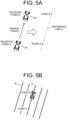
- the operator sets a reference line L1 for generating the straight route as the target route R.
- a desired location for example, an outer circumferential end
- the operator manually drives the work vehicle 10 in a direction (a target direction) in which the operator wants the work vehicle 10 to travel and work. More specifically, the operator drives the work vehicle 10 straight in a direction that is parallel to a work direction (a tillage direction, for example) at the time when the work vehicle 10 works at a workplace.
- the operator operates (for example, touches) an operation display unit 73 (see Fig. 3 ) twice at the desired location (for example, an end of the workplace in a front-rear direction).
- the vehicle controller 11 registers a location (a point A) of the work vehicle 10 by the operator's first operation and registers a location (a point B) of the work vehicle 10 by the operator's second operation.
- the vehicle controller 11 sets a straight line that passes through the point A and the point B as the reference line L1 (see Fig. 5A ).
- the vehicle controller 11 may be able to register the point B in the case where the work vehicle 10 travels for a predetermined distance (for example, 5 m) after the point A is registered. In this way, it is possible to set the further accurate reference line L1.
- the vehicle controller 11 generates a travel route (the target route R) including the reference line L1 and plural straight lines that are parallel to the reference line L1. For example, based on a work width (a lateral width of the work machine 14) and a lap width (a width that overlaps an adjacent worked area), which are set in advance, the vehicle controller 11 generates the plural parallel straight lines at equally-spaced intervals in a right and left direction with the reference line L1 being a center (see Fig. 5B ). The vehicle controller 11 registers the generated target route R in the storage unit 12 and causes the operation device 17 to display the generated target route R.
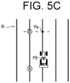
- the operator drives the work vehicle 10 straight in the field F by automatic steering after the target route R is generated, the operator moves the work vehicle 10 by manual steering while seeing the target route R displayed in the operation device 17 such that a direction (an orientation) of the work vehicle 10 falls within a predetermined range (a predetermined orientation) with respect to a direction of the reference line L1 (an autonomous travel start condition is satisfied) (see Fig. 5C ).
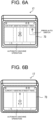
- Fig. 6A illustrates an operation screen (a work screen) showing that the work vehicle 10 satisfies the autonomous travel start condition and thus is brought into a state of enabling the autonomous travel.
- the vehicle controller 11 causes the operation display unit 73 to display the operation screen illustrated in Fig. 6A .
- the operator presses an autonomous travel button (not illustrated) in the operation display unit 73 and issues a travel start instruction.
- the vehicle controller 11 starts the automatic steering of the work vehicle 10 such that the work vehicle 10 travels along the straight route that is closest to a current location P0 (see Fig. 5C ). In this way, the vehicle controller 11 causes the work vehicle 10 to travel autonomously along the straight route by the automatic steering.
- Fig. 6B illustrates a display screen (a work screen) that is shown during the autonomous travel of the work vehicle 10.
- the vehicle controller 11 causes the operation device 17 to display the work screen illustrated in Fig. 6B .
- the operation device 17 displays the location of the work vehicle 10, the straight route, the worked area (a work status), guidance information (will be described below), and the like on the work screen of the operation display unit 73.
- the first travel pattern of the autonomous travel is configured that the target route R is generated in advance according to the work width and the lap width of the work vehicle 10 and the work vehicle 10 thereby travels autonomously.
- a second travel pattern of the autonomous travel it may be configured that the target route R is generated with the location of the work vehicle 10 being a reference and the work vehicle 10 thereby travels autonomously.
- the vehicle controller 11 causes the work vehicle 10 to travel straight from such a location in parallel with the reference line L1 by the automatic steering.
- the vehicle controller 11 may apply the first travel pattern or the second travel pattern according to the operator's selection operation. For example, the vehicle controller 11 may cause the operation device 17 to display a first route generation mode corresponding to the first travel pattern and a second route generation mode corresponding to the second travel pattern to be selectable, and may make the autonomous travel by the route generation mode selected by the operator.
- the vehicle controller 11 notifies (displays a message, provides voice guidance, or the like for) the operator of information on arrival at the end Pe (the guidance information, which will be described below).
- the operator terminates the automatic steering.
- the vehicle controller 11 switches the travel mode to the manual travel.
- the vehicle controller 11 may switch the travel mode to the manual travel when determining that the work vehicle 10 has arrived at the end Pe, or may switch the travel mode to the manual travel in response to the operator's operation.
- the travel mode is switched to the manual travel, for example, the operator performs turning travel (the manual travel) of the work vehicle 10 by the manual steering.
- the vehicle controller 11 switches the travel mode in response to the operator's operation on the operation device 17, causes the work vehicle 10 to travel autonomously on the straight route (the target route R) by the automatic steering, and causes the work vehicle 10 to travel manually on the turning road by the manual steering.
- a technique of displaying the guidance information, driving information, and the like related to the autonomous travel on a display device (corresponding to the operation device 17 in the present embodiment) to assist with the operator's operation has conventionally been known.
- the information is uniformly displayed on the display device.
- the conventional technique has a problem of degraded convenience of an operation terminal (the operation device 17) that displays the information on the travel of the work vehicle.
- the configuration in the present embodiment it is possible to improve the convenience of the operation terminal (the operation device 17) that displays the information on the travel of the work vehicle. A description will hereinafter be made on a specific configuration of the operation device 17.
- the operation device 17 includes an operation control unit 71, a storage unit 72, an operation display unit 73, and the like.
- the operation device 17 may be a device that can be attached/detached to/from the work vehicle 10.
- the operation device 17 may be a mobile terminal (the tablet terminal, the smartphone, or the like) that can be carried by the operator.
- the operation device 17 is communicably connected to the vehicle controller 11 in the wired or wireless manner.
- the operation display unit 73 is a user interface that includes: a display such as a liquid-crystal display or an organic EL display for displaying the various types of the information; and an operation unit such as operation buttons or a touch panel that accepts operations.
- the operation display unit 73 displays any of the various setting screens, work screens, and the like in response to an instruction from the operation control unit 71.
- the operation display unit 73 accepts the operator's operation on the setting screen or the work screen.
- the operation unit includes: the autonomous travel button that is used by the operator to issue the travel start instruction when the operator starts the autonomous travel of the work vehicle 10; an offset button that is used for an offset operation (a correction operation) to correct a location deviation between the work vehicle 10 and the target route R; and plural selection buttons, each of which is used for the selection operation on the setting screen or the work screen (none of those is illustrated).
- the operation device 17 is an example of the operation terminal in the present invention.
- the operation device 17 is installed near the steering wheel 137 in the cabin 18.
- the storage unit 72 is a non-volatile storage unit such as an HDD or an SSD that stores the various types of the information.
- the storage unit 72 stores a control program such as an operation assistance program for causing the operation device 17 to execute operation assistance processing (see Fig. 14 ), which will be described below.
- the operation assistance program is non-transiently recorded in a computer-readable recording medium such as a CD or a DVD, is read by a predetermined reader (not illustrated), and is stored in the storage unit 72.
- the operation assistance program may be downloaded to the operation device 17 from a server (not illustrated) via the communication network and stored in the storage unit 72.
- the operation assistance program may be stored in the storage unit 12 of the work vehicle 10.
- the storage unit 72 may store the data on the target route R that is generated in the operation device 17.
- the operation control unit 71 has control devices such as a CPU, ROM, and RAM.
- the CPU is the processor that executes the various types of the arithmetic processing.
- the ROM is the non-volatile storage unit that stores, in advance, the control programs such as the BIOS and the OS for causing the CPU to execute the various types of the arithmetic processing.
- the RAM is the volatile or non-volatile storage unit that stores the various types of the information, and is used as the transient storage memory (the workspace) for the various types of the processing executed by the CPU. Then, when the CPU executes the various control programs, which are stored in the ROM or the storage unit 72 in advance, the operation control unit 71 controls the operation device 17.
- the operation control unit 71 includes various processing units such as a display processing unit 711, an acceptance processing unit 712, and a setting processing unit 713.
- the operation device 17 functions as each of the various processing units when the CPU executes the respective processing according to the operation assistance program. Some or all of the processing units may each be constructed of an electronic circuit.
- the operation assistance program may be a program that causes plural processors to function as the processing units.
- the display processing unit 711 causes the operation display unit 73 to display the various types of the information.
- the display processing unit 711 causes the operation display unit 73 to display: any of the setting screens ( Figs. 10A, 10B to Figs. 13A, 13B , 13C , and the like) on which various settings are made; any of work screens D1 ( Fig. 8, Fig. 9 , and the like) including the travel information of the work vehicle 10 such as a travel status and the work status; and the like.
- the display processing unit 711 is an example of each of the first display processing unit and the second display processing unit in the present invention.
- the acceptance processing unit 712 accepts the various operations by the operator. For example, on the setting screen, the acceptance processing unit 712 accepts, from the operator, an operation to set a display target (the travel information) to be displayed the work screen D1.
- a display target the travel information
- Fig. 7 illustrates plural display areas A0 to A4 that are set on the work screen D1.
- the operation control unit 71 sets the display areas A0 to A4 in advance for the display screen (the work screen D1).
- the display area A0 is an entire area where the location of the work vehicle 10, the target route R, and the like can be displayed.
- the display area A0 includes the plural display areas A1 to A4.
- the display area A1 is arranged in a lower portion of the display area A0
- the display area A2 and the display area A3 are aligned vertically in a left portion of the display area A0
- the display area A4 is arranged in a right portion of the display area A0.
- the display areas A1 to A4 are arranged in a manner to be partially superimposed on the display area A0.
- the arrangement locations of the display areas A1 to A4 are not limited to the locations illustrated in Fig. 7 .
- the arrangement locations and ranges of the display areas A1 to A4 may be changeable according to the operator's operation.
- the display areas A0 to A4 may be arranged in a manner not to overlap each other.
- text information indicating the travel status of the work vehicle 10 (for example, "CURRENTLY ASSISTING STRAIGHT TRAVEL") is displayed above the display areas A0 to A4.
- icon images representing the travel status, a setting status, and the like of the work vehicle 10 are displayed.
- an icon image C1 is an image representing whether to link a function of an instruction to start the autonomous travel with an operation tool (for example, a lifting/lowering lever of the work machine 14).
- an operation tool for example, a lifting/lowering lever of the work machine 14.
- the work vehicle 10 starts the autonomous travel and lowers the work machine 14 to start the work.
- the icon image C1 is unlit, the work vehicle 10 does not start the autonomous travel and only performs operation to lower the work machine 14 even when the operator lowers the lifting/lowering lever.
- the operator may perform the operation (an ON/OFF operation) of whether to link an autonomous travel start function with the operation tool on the setting screen (not illustrated) or in a selection section Ks of the work screen D1.
- An icon image H1 is an image representing a correction amount (an offset amount) when the operator performs the offset operation (the correction operation) to correct the location deviation between the work vehicle 10 and the target route R.
- a correction amount an offset amount
- the offset amount is displayed in a right icon image HR.
- the offset amount is displayed in a left icon image HL.
- An icon image C2 is an image representing that the work vehicle 10 during the autonomous travel is arriving at an end point (the end Pe (see Fig. 5C )) of the straight route.
- the icon image C2 is lit when the work vehicle 10 approaches the end point.
- An icon image C3 is an image representing a state of positioning accuracy (location accuracy) of the work vehicle 10.
- the icon image C3 is displayed in a color that corresponds to the state of the positioning accuracy.
- the display processing unit 711 may change a display mode of each of the icon images according to a travel state of the work vehicle 10.
- the setting processing unit 713 sets the display target (the travel information) for each of the display areas A1 to A4. More specifically, when the acceptance processing unit 712 accepts, from the operator, an operation to select the display target for the display area on the setting screen, the setting processing unit 713 executes processing to register the display target selected by the operator in association with the display area.
- the display processing unit 711 causes the operation display unit 73 to display the work screen D1 on the basis of setting information that is set (registered) by the setting processing unit 713.
- Fig. 8 and Fig. 9 each illustrate an example of the work screen D1 during the autonomous travel of the work vehicle 10.
- travel information G0 is displayed in the display area A0 (see Fig. 7 ), but the travel information is not displayed in the display areas A1 to A4 (see Fig. 7 ).
- the travel information G0 includes the location of the work vehicle 10 with respect to the target route R (the straight route), the target route R (the plural parallel lines), the point B that corresponds to the end point, and the like.
- the display processing unit 711 displays the travel information G0 (first information) on the location of the work vehicle 10 in the display area A0.
- the travel information G0 which includes the location of the work vehicle 10, the target route R, the point B, the worked area, and the like, is displayed in the display area A0
- travel information G1 indicating the location deviation between the work vehicle 10 and the target route R
- travel information G2 indicating the vehicle speed of the work vehicle 10
- travel information G3 indicating the lap width of the work vehicle 10
- travel information G4 (the guidance information and operation guidance information) indicating that the work vehicle 10 is approaching the end point is displayed in the display area A4.
- the display processing unit 711 displays a location deviation K0 ("16 cm" in Fig.
- the display processing unit 711 displays the travel information G0 at a center of the work screen D1 in the display area A0, displays the travel information G1 at the lower center of the work screen D1 in the display area A0, displays the travel information G2 and the travel information G3 on the left side of the center of the work screen D1 in the display area A0, and displays the travel information G4 on the right side of the center of the work screen D1 in the display area A0.
- the operation control unit 71 may audibly output (provide voice guidance of) the contents corresponding to the travel information G1 to G4.
- the operation control unit 71 may audibly output a display content of the travel information G4 at timing at which the display content is switched, and may audibly output a display content of each of the travel information G1 to G3 at timing at which a set value is changed, at timing at which a change amount exceeds a predetermined amount, or at timing at which the display content is switched.
- the setting processing unit 713 can switch between the setting to display the travel information G1 to G4 on the travel state of the work vehicle 10 in the display areas A1 to A4 included in the work screen D1 and the setting not to display the travel information G1 to G4 in the display areas A1 to A4.
- the acceptance processing unit 712 can accept, from the operator, an operation for the setting to display the travel information G1 to G4 in the display areas A1 to A4 (a first setting operation) or an operation for the setting not to display the travel information G1 to G4 in the display areas A1 to A4 (a second setting operation).
- the setting processing unit 713 can be configured to display the travel information G0 in the display area A0 and display the travel information G1 to G4 in the display areas A1 to A4 when accepting the first setting operation from the operator, and can be configured to display the travel information G0 in the display area A0 but not to display the travel information G1 to G4 in the display areas A1 to A4 when accepting the second setting operation from the operator.
- the operator can freely customize the display contents of the work screen D1.
- the display area A0 is an example of the first display area in the present invention
- each of the display areas A1 to A4 is an example of the second display area in the present invention
- the display area A5 is an example of the third display area in the present invention
- the travel information G0 is an example of the first information in the present invention
- each of the travel information G1 to G4 is an example of the second information in the present invention.
- Fig. 10A illustrates an example of a setting screen P1.
- the setting screen P1 includes: a setting item ("WORK HISTORY”) to select whether to display the worked area (see the travel information G0 in Fig. 9 ) in the display area A0 (see Fig. 7 ); a setting item K11 ("DEVIATION AMOUNT DISPLAY") to select whether to display the location deviation K0 (the travel information G1 in Fig. 9 ) in the display area A1 (see Fig.
- buttons K1 to K3 is an example of the operation unit in the operation display unit 73.
- the display processing unit 711 displays a setting screen P11 illustrated in Fig. 10B .
- the display processing unit 711 displays a selection field for selecting ON/OFF of the display of the location deviation K0 and explanatory information about the location deviation K0 on the setting screen P11.
- the operator selects ON and presses the enter button K2 when the operator wishes to display the travel information G1 on the location deviation K0 (see Fig. 9 ) on the work screen D1.
- the operator selects OFF and presses the enter button K2.
- the operation in which the operator selects ON is an example of the first setting operation in the present invention
- the operation in which the operator selects OFF is an example of the second setting operation in the present invention.
- the setting processing unit 713 sets the display content of the display area A1 on the basis of the selection operation (an ON/OFF operation). In the example illustrated in Fig. 10B , since the operator selects ON, the setting processing unit 713 registers the travel information G1 in association with the display area A1.
- the display processing unit 711 displays a setting screen P12 illustrated in Fig. 11B .
- the display processing unit 711 displays a selection field for selecting ON/OFF of the display of the travel information G4 and explanatory information about the travel information G4 on the setting screen P12.
- the setting processing unit 713 sets the display content of the display area A4 on the basis of the selection operation (the ON/OFF operation). In the example illustrated in Fig. 11B , since the operator selects ON, the setting processing unit 713 registers the travel information G4 in association with the display area A4.
- the setting screen P2 includes: a setting item K21 ("INFORMATION DISPLAY 1") for selecting whether to display the travel information G2 (see Fig. 9 ) in the display area A2 (see Fig. 7 ) and for selecting the display target to be displayed in the display area A2; a setting item K22 ("INFORMATION DISPLAY 2") for selecting whether to display the travel information G3 (see Fig. 9 ) in the display area A3 (see Fig. 7 ) and for selecting the display target to be displayed in the display area A3; and the like.
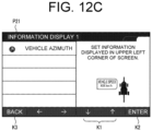
- the display processing unit 711 displays a setting screen P21 illustrated in Fig. 12B .
- the display processing unit 711 displays a selection field for selecting OFF of the display of the travel information G2, selection fields of the plural display targets, and explanatory information corresponding to each of the selection fields on the setting screen P21.
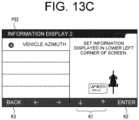
- the plural display targets include "VEHICLE SPEED”, “WORK WIDTH”, “LAP WIDTH”, “ROUTE AZIMUTH”, “VEHICLE AZIMUTH” (see Fig. 12C ), and the like. "VEHICLE AZIMUTH” is displayed on the next page (see Fig. 12C ) of the display page illustrated in Fig. 12B .
- the operator selects a setting item K23 "VEHICLE SPEED" and presses the enter button K2.
- the acceptance processing unit 712 accepts the operator's selection operation
- the setting processing unit 713 registers the display target in association with the display area A2 where the travel information G2 is displayed.
- the setting processing unit 713 registers the travel information G2 of "VEHICLE SPEED” in association with the display area A2.
- the operation in which the operator selects any of the plural display targets is an example of the first setting operation in the present invention.
- the display processing unit 711 displays a setting screen P22 illustrated in Fig. 13B .
- the display processing unit 711 displays a selection field for selecting OFF of the display of the travel information G3, the selection fields of the plural display targets, and the explanatory information corresponding to each of the selection fields on the setting screen P22.
- the plural display targets include "VEHICLE SPEED”, “WORK WIDTH”, “LAP WIDTH”, “ROUTE AZIMUTH”, "VEHICLE AZIMUTH” (see Fig. 13B and Fig.
- the plural selectable display targets corresponding to the information display 1 are the same as the plural selectable display targets corresponding to the information display 2 (the display area A3) (see Fig. 13B and Fig. 13C ).
- the plural selectable display target may differ between the display area A2 and the display area A3.
- the operator selects a setting item K24 "LAP WIDTH” and presses the enter button K2 (see Fig. 13B ).
- the acceptance processing unit 712 accepts the operator's selection operation
- the setting processing unit 713 registers the display target in association with the display area A3 where the travel information G3 is displayed.
- the setting processing unit 713 registers the travel information G3 of "LAP WIDTH” in association with the display area A3.
- the setting processing unit 713 registers the travel information G0 (see Fig. 9 ) of the worked area (the work history) in association with the display area A0.
- the setting processing unit 713 sets the display contents of the work screen D1 according to the operator's setting operation.
- the display processing unit 711 causes the operation display unit 73 to display the work screen D1 illustrated in Fig. 9 during the autonomous travel of the work vehicle 10.
- the display processing unit 711 displays the travel information G0, which includes the location of the work vehicle 10, the target route R, the point B, and the worked area, in the display area A0, displays the travel information G1 indicating the location deviation K0 in the display area A1, displays the travel information G2 indicating the vehicle speed of the work vehicle 10 in the display area A2, displays the travel information G3 indicating the lap width of the work vehicle 10 in the display area A3, and displays the travel information G4 indicating that the work vehicle 10 is approaching the end point in the display area A4.
- the operation control unit 71 can display mutually different types of the travel information on the travel state of the work vehicle 10 in the plural display areas.
- the travel information may include information that corresponds to each of the plural setting items related to the travel state of the work vehicle 10.
- the display processing unit 711 displays the travel information that corresponds to the selected setting item in the display area.
- the operation control unit 71 may be configured not to accept the selection operation of the setting item (see Fig. 12B ), which is selected for "INFORMATION DISPLAY 1" (the display area A2), on the setting screen P22 (see Fig. 13B ) of "INFORMATION DISPLAY 2" (the display area A3), for example, such that the display contents of the travel information G2 and the travel information G3 (see Fig. 9 ) are not the same.
- the operation control unit 71 hides or gray outs the setting item "VEHICLE SPEED" on the setting screen P22 illustrated in Fig. 13B .
- the operation control unit 71 may display the setting item, which is selected in Fig. 12B , to be identifiable on the setting screen P22 illustrated in Fig. 13B .
- the operation control unit 71 displays identification information (a message of "SELECTED” or the like) in the setting item "VEHICLE SPEED" on the setting screen P22 illustrated in Fig. 13B .
- the present invention may be comprehended as the invention of the operation assistance method by which the operation device 17 partially or entirely executes the operation assistance processing or the invention of the operation assistance program for causing the operation device 17 to partially or entirely execute the operation assistance method.
- One or plural processors may execute the operation assistance processing.
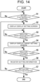
- step S1 the operation control unit 71 determines whether a start instruction of the setting operation has been accepted from the operator. For example, the operator selects the display setting (not illustrated) on the menu screen when setting the travel information to be displayed on the work screen D1. If the operation control unit 71 has accepted the selection operation of the display setting (a setting start instruction) from the operator (S1: Yes), the processing proceeds to step S2. The operation control unit 71 stands by until accepting the setting start instruction from the operator (S1: No).
- step S2 the operation control unit 71 displays the setting screen P1.
- the operation control unit 71 causes the operation display unit 73 to display the setting screen P1 illustrated in Fig. 10A .
- the setting screen P1 illustrated in Fig. 10A includes: the setting item K11 "DEVIATION AMOUNT DISPLAY" that corresponds to the location deviation K0; and the setting item K12 "OPERATION GUIDE DISPLAY" that corresponds to the guidance information (the operation guidance information).
- step S3 the operation control unit 71 determines whether the selection operation of the setting item has been accepted from the operator. For example, the operator selects the setting item K11 on the work screen D1 (see Fig. 10A ). If the operation control unit 71 has accepted the selection operation of the setting item from the operator (S3: Yes), the processing proceeds to step S4. The operation control unit 71 stands by until accepting the selection operation of the setting item from the operator (S3: No).
- step S4 the operation control unit 71 displays the display target setting screen. For example, when the operator selects the setting item K11 on the work screen D1 (see Fig. 10A ), the operation control unit 71 displays the setting screen P11 illustrated in Fig. 10B . The operation control unit 71 displays the selection field for selecting ON/OFF of the display of the location deviation K0 on the setting screen P11.
- step S5 the operation control unit 71 determines whether the selection operation of the display target has been accepted. For example, the operation control unit 71 accepts the operator's selection operation on the setting screen P11 illustrated in Fig. 10B . If the operation control unit 71 has accepted the selection operation from the operator (S5: Yes), the processing proceeds to step S6.
- the operation control unit 71 stands by until accepting the selection operation from the operator (S5: No). For example, when the operator wishes to display the travel information G1 on the location deviation K0 (see Fig. 9 ) on the work screen D1, the operator selects ON and presses the enter button K2. On the other hand, when the operator does not wish to display the travel information G1 on the work screen D1, the operator selects OFF and presses the enter button K2.
- Step S6 the operation control unit 71 registers the setting information. For example, when the operator selects ON on the setting screen P11 illustrated in Fig. 10B , the operation control unit 71 registers the travel information G1 in association with the display area A1. Meanwhile, for example, when the operator selects OFF on the setting screen P11 illustrated in Fig. 10B , the operation control unit 71 does not associate the travel information with the display area A1 or registers a non-display flag in association with the display area A1.
- step S7 the operation control unit 71 determines whether a setting operation end instruction has been accepted from the operator. For example, when the operator performs an operation to start the autonomous travel on the menu screen, the operation control unit 71 accepts the setting operation end instruction. If the operation control unit 71 has accepted the end instruction from the operator (S7: Yes), the operation control unit 71 terminates the operation assistance processing. On the other hand, if the operation control unit 71 has not accepted the end instruction from the operator (S7: No), the processing proceeds to step S2.
- step S2 the operation control unit 71 displays the setting screen P1 (see Fig. 11A ). If the operator selects the setting item K12 on the setting screen P1 (S3: Yes), the operation control unit 71 displays the setting screen P12 illustrated in Fig. 11B (S4) and accepts the selection operation to select ON/OFF of the display of the travel information G4 (the operation guidance information) (S5). When the operator selects ON on the setting screen P12, the operation control unit 71 registers the travel information G4 in association with the display area A4 (S6).
- the operation control unit 71 displays the setting screen P2 (see Fig. 12A ) (S2). If the operator selects the setting item K21 on the setting screen P2 (S3: Yes), the operation control unit 71 displays the setting screen P21 illustrated in Fig. 12B (S4) and accepts the selection operation to select the display target (S5).
- the operation control unit 71 registers vehicle speed information (the travel information G2) in association with the display area A2 (S6).
- step S2 the operation control unit 71 displays the setting screen P2 (see Fig. 13A ). If the operator selects the setting item K22 on the setting screen P2 (S3: Yes), the operation control unit 71 displays the setting screen P22 illustrated in Fig. 13B (S4) and accepts the selection operation to select the display target (S5). When the operator selects "LAP WIDTH" on the setting screen P22, the operation control unit 71 registers lap width information (the travel information G3) in association with the display area A3 (S6).
- lap width information the travel information G3
- the operation control unit 71 terminates the operation assistance processing.
- the operation control unit 71 executes the operation assistance processing every time the operation control unit 71 accepts the start instruction of the setting operation by the operator.
- the operation control unit 71 can also execute the operation assistance processing during the autonomous travel of the work vehicle 10.
- the operation device 17 causes the operation device 17, which is used for the travel operation of the work vehicle 10, to display the work screen D1, and displays the travel information G0 on the location of the work vehicle 10 in the display area A0 included in the work screen D1.
- the operation device 17 switches between the setting to display the travel information G0 to G4 on the travel state of the work vehicle 10 in the display areas A1 to A4 included in the work screen D1 and the setting not to display the travel information G0 to G4 in the display areas A1 to A4.
- the travel information G1 to G4 includes at least one of the information on the travel status of the work vehicle 10, the information on the work status of the work vehicle 10, and the guidance information (the operation guidance information).
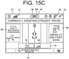
- the display area A2 and the display area A3 are set in a manner to be aligned vertically in the left portion of the work screen D1, and the display target can be set in each of the display area A2 and the display area A3. Accordingly, for example, in the case where the operator sets "ROUTE AZIMUTH" for "INFORMATION DISPLAY 1" (the display area A2) and “OFF” for "INFORMATION DISPLAY 2" (the display area A3) on the setting screen P2 in Fig. 12A and Fig. 13A , as illustrated in the work screen D1 in Fig.
- the operation control unit 71 the travel information G2 indicating the route azimuth corresponding to the reference line L1 in the display area A2 and brings the display area A3 into a non-displayed state.
- the operation control unit 71 displays the set azimuth as the route azimuth in the display area A2.
- the operation control unit 71 may display associated information that is associated with the display target in the other display area. For example, in the case where the operator sets the set azimuth to "90 DEGREES", as illustrated in Fig.
- the operation control unit 71 displays the travel information G2 indicating the route azimuth "90 DEGREES” in the display area A2 while displaying, in the display area A3, the travel information G3 indicating "270 DEGREES" in the same direction as the route azimuth "90 DEGREES".
- the operator may set an angle "d1" for the reference line L1 or may set an angle "d1 + 180 DEGREES” for the reference line L1.
- the operation control unit 71 may set a single display area where the display areas A2, A3 are integrated, and may display the travel information G5 including the associated information in the integrated display area. Just as described, the operation control unit 71 may change the display content to be displayed in the display area according to the size of the display area.
- the single display target (the information indicating that the work vehicle 10 is approaching the end point) is exemplified as the travel information G4 (the guidance information) that corresponds to the display area A4 (see Fig. 11B ).
- the travel information G4 is not limited thereto.
- the operation control unit 71 may display each piece of the guidance information illustrated in (a) to (h) in the display area A4. For example, when the operator sets "OPERATION GUIDE DISPLAY" to "ON" (see Fig. 11A and Fig. 11B ), the operation control unit 71 may switch the display target of the display area A4 according to the state of the work vehicle 10.
- the operation control unit 71 displays, in the display area A4 of the work screen D1, the guidance information (a) indicating that the work vehicle 10 arrives at the end point soon.
- the operation control unit 71 displays, in the display area A4 of the work screen D1, the guidance information (b), (c) that urge the registration operation of the point A and the point B.
- the operation control unit 71 displays, in the display area A4 of the work screen D1, the guidance information (d) that urges the user to the start instruction of the autonomous travel (pressing of the AUTO switch) (see Fig. 6A ).
- the operation control unit 71 displays, in the display area A4 of the work screen D1, the guidance information (e) indicating that the location accuracy is degraded.
- the operation control unit 71 displays, in the display area A4 of the work screen D1, the guidance information (f) on the display area A4 of the work screen D1 that urges the operator to be seated.
- the operation control unit 71 displays, in the display area A4 of the work screen D1, the guidance information (g) indicating that the work vehicle 10 deviates from the target route R.
- the operation control unit 71 displays the guidance information (h) indicating that the vehicle speed exceeds an applicable vehicle speed range.
- the operation control unit 71 may switch the display target (the guidance information) of the display area A4 according to the state of the work vehicle 10 (the setting status, the travel status, or the like).
- the operator may be able to select any one of the guidance information (a) to (h) as the display target to be displayed in the display area A4.
- the operation control unit 71 may audibly output the contents corresponding to the guidance information (a) to (h).
- the operation control unit 71 may only provide the voice guidance even when the setting item K12 (see Fig. 11B ) of "OPERATION GUIDE DISPLAY" is set to OFF.
- the operation control unit 71 may be able to switch ON/OFF of the voice guidance.
- the operator selects the display target in each of the setting screens (see Figs. 10A, 10B to Figs. 13A, 13B , 13C ).
- the operator selects any of the display areas A0 to A4 to set the display target.
- the operation control unit 71 displays the setting screen P21 (see Fig. 12B and Fig. 12C ) that corresponds to the display area A2, and accepts the selection operation of the display target from the operator.
- the operation control unit 71 displays the setting screen P22 (see Fig. 13B and Fig. 13C ) that corresponds to the display area A3, and accepts the selection operation of the display target from the operator.
- the operator may be able to change the position and the range of each of the display areas A0 to A4.
- the operator may be able to select and move a rectangular frame of the display area A2 or change a range of the rectangular frame.
- the operator may be able to customize the display position and the display range of each of the travel information G0 to G4.
- the operation control unit 71 may change the display content to be displayed in the display area according to the size (the range) of the display area. For example, in the case where the display area is small, the operation control unit 71 displays a simplified version (basic information) of the travel information in the display area. In the case where the display area is large, the operation control unit 71 displays a detailed version (the basic information and associated information) of the travel information in the display area.
- the operation control unit 71 may display (expand the display of) the travel information G0 in the display area A0 that corresponds to the display areas A2, A3.
- the operation control unit 71 may display (expand the display of) the travel information G0 in the display area A0 that corresponds to the display areas A1 to A4.
- the operation control unit 71 may change the display content of the travel information G0 according to the setting state of the display or the non-display of the display areas A1 to A4 included in the display area A0.
- the operation control unit 71 may always display (expand the display of) the travel information G0 in the entire display area A0, and may superimpose the travel information G1 to G4 over the travel information G0 when the display target is set in each of the display areas A1 to A4.
- the operation control unit 71 may display the guidance information in a manner to correspond to the icon image that is displayed in the display area A5 (see Fig. 7 ) of the work screen D1. For example, when the operator selects (performs the touch operation on the touch panel) the icon image C2 on the work screen D1 illustrated in Fig. 17B , as the guidance information that corresponds to the icon image C2, the operation control unit 71 displays the travel information G4 ((a) in Fig. 16 ) in the display area A4 (see Fig. 17A ). In addition, for example, when the operator selects (performs the touch operation of) the icon image C3 on the work screen D1 illustrated in Fig.
- the operation control unit 71 displays information on the positioning state ((e) in Fig. 16 ) in the display area A4. Furthermore, for example, when the operator selects (performs the touch operation of) the icon image C1 on the work screen D1 illustrated in Fig. 17B , as the guidance information that corresponds to the icon image C1, the operation control unit 71 displays information on a state of the linkage function of the autonomous travel start operation (for example, "SETTING TO START AUTONOMOUS TRAVEL WITH LOWERING OPERATION OF LIFTING/LOWERING LEVER IS ON" or the like) in the display area A4.
- a state of the linkage function of the autonomous travel start operation for example, "SETTING TO START AUTONOMOUS TRAVEL WITH LOWERING OPERATION OF LIFTING/LOWERING LEVER IS ON" or the like
- the operation control unit 71 may determine the travel information G1 to G4 to be displayed in the display areas A1 to A4 on the basis of setting history information by the operator. For example, the operation control unit 71 prioritizes the travel information corresponding to the setting item with high selection frequency of the setting items that have been selected by the operator in the past, and displays such travel information in the display area. When the operator changes the setting item, the operation control unit 71 prioritizes the travel information corresponding to the changed setting item and displays such travel information in the display area.
- the operation control unit 71 may switch the setting to the display of the guidance information. For example, in the case where the operator does not issue the travel start instruction with high frequency even when the autonomous travel start condition is satisfied, the operation control unit 71 switches the setting to the display of the guidance information (the travel information G4) in the display area A4. In addition, in the case where the operator does not perform the end operation with high frequency even when the work vehicle 10 during the autonomous travel has arrived at the end point, the operation control unit 71 switches the setting to the display of the guidance information (the travel information G4) in the display area A4.
- the work vehicle 10 in the present invention may also be able to travel autonomously when turning.
- the target route R includes the straight route and the turning road.
- the operator may be able to switch between the autonomous travel and the manual travel during the turn.
- the unmanned autonomous travel of the work vehicle 10 may be allowed on the target route R.
- the operator may remotely control the operation terminal to make the travel start instruction or the like.
- the operation terminal that is used for the remote control may be the operation device 17 according to the present embodiment or may include each of the processing units in the operation device 17.
- the operation assistance system according to the present invention may be constructed of the operation device 17 alone or may be constructed of the server that includes each of the processing units provided in the operation device 17.
- the operation assistance system may be constructed of the work vehicle 10 that includes the operation device 17.
Landscapes
- Engineering & Computer Science (AREA)
- Combustion & Propulsion (AREA)
- Transportation (AREA)
- Mechanical Engineering (AREA)
- Chemical & Material Sciences (AREA)
- Radar, Positioning & Navigation (AREA)
- Remote Sensing (AREA)
- Physics & Mathematics (AREA)
- Automation & Control Theory (AREA)
- Aviation & Aerospace Engineering (AREA)
- General Physics & Mathematics (AREA)
- Computing Systems (AREA)
- Evolutionary Computation (AREA)
- Mathematical Physics (AREA)
- Theoretical Computer Science (AREA)
- Business, Economics & Management (AREA)
- Health & Medical Sciences (AREA)
- Artificial Intelligence (AREA)
- General Engineering & Computer Science (AREA)
- Game Theory and Decision Science (AREA)
- Medical Informatics (AREA)
- Guiding Agricultural Machines (AREA)
- Control Of Position, Course, Altitude, Or Attitude Of Moving Bodies (AREA)
- Fittings On The Vehicle Exterior For Carrying Loads, And Devices For Holding Or Mounting Articles (AREA)
- Instrument Panels (AREA)
Abstract
Description
- The present invention relates to an operation assistance method, an operation assistance system, and an operation assistance program for assisting with an operator's operation on an operation terminal that is used for a travel operation of a work vehicle.
- The following technique has been known. In the technique, guidance information, driving information, and the like related to autonomous travel are displayed on a display device when a work vehicle travels autonomously in a field (for example, see Patent Document 1).
- Patent Document 1:
Japanese Unexamined Patent Application Publication No. 2019-127119 - However, in the conventional technique, the information is uniformly displayed on the display device. Thus, even when the information is useful for a certain user (an operator), such information may be unnecessary for another user. For example, constant display of the guidance information is bothersome for a skilled operator. Just as described, the conventional technique has a problem of degraded convenience of the operation terminal that displays the information on the travel of the work vehicle.
- The present invention has a purpose of providing an operation assistance method, an operation assistance system, and an operation assistance program capable of improving convenience of an operation terminal that displays information on travel of a work vehicle.
- An operation assistance method according to the present invention executes: displaying a display screen on an operation terminal that is used for a travel operation of a work vehicle; displaying first information on a location of the work vehicle in a first display area included in the display screen; and switching between a setting to display second information on a travel state of the work vehicle in a second display area included in the display screen and a setting not to display the second information in the second display area.
- An operation assistance system according to the present invention includes a first display processing unit, a second display processing unit, and a setting processing unit. The first display processing unit displays a display screen on an operation terminal that is used for a travel operation of a work vehicle. The second display processing unit displays first information on a location of the work vehicle in a first display area included in the display screen. The setting processing unit switches between a setting to display second information on a travel state of the work vehicle in a second display area included in the display screen and a setting not to display the second information in the second display area.
- An operation assistance program according to the present invention is an operation assistance program for causing one or plural processors to: display a display screen on an operation terminal that is used for a travel operation of a work vehicle; display first information on a location of the work vehicle in a first display area included in the display screen; and switch between a setting to display second information on a travel state of the work vehicle in a second display area included in the display screen and a setting not to display the second information in the second display area.
- The present invention can provide the operation assistance method, the operation assistance system, and the operation assistance program capable of improving convenience of the operation terminal that displays the information on travel of the work vehicle.
-
-
Fig. 1 is a block diagram illustrating a configuration of a work vehicle according to an embodiment of the present invention. -
Fig. 2 is an external view illustrating an example of the work vehicle according of the embodiment of the present invention. -
Fig. 3 is an external view illustrating an example of an operation device according to the embodiment of the present invention. -
Fig. 4 is a view illustrating an example of a target route of the work vehicle according to the embodiment of the present invention. -
Fig. 5A is a view for explaining a travel method for autonomous travel of the work vehicle according to the embodiment of the present invention. -
Fig. 5B is a view for explaining the travel method for the autonomous travel of the work vehicle according to the embodiment of the present invention. -
Fig. 5C is a view for explaining the travel method for the autonomous travel of the work vehicle according to the embodiment of the present invention. -
Fig. 6A is a view illustrating an example of a work screen that is displayed in an operation device according to the embodiment of the present invention. -
Fig. 6B is a view illustrating an example of the work screen that is displayed in the operation device according to the embodiment of the present invention. -
Fig. 7 is a view illustrating a configuration of the work screen that is displayed in the operation device according to the embodiment of the present invention. -
Fig. 8 is a view illustrating an example of the work screen that is displayed in the operation device according to the embodiment of the present invention. -
Fig. 9 is a view illustrating an example of the work screen that is displayed in the operation device according to the embodiment of the present invention. -
Fig. 10A is a view illustrating an example of a setting screen that is displayed in the operation device according to the embodiment of the present invention. -
Fig. 10B is a view illustrating an example of the setting screen that is displayed in the operation device according to the embodiment of the present invention. -
Fig. 11A is a view illustrating an example of the setting screen that is displayed in the operation device according to the embodiment of the present invention. -
Fig. 11B is a view illustrating an example of the setting screen that is displayed in the operation device according to the embodiment of the present invention. -
Fig. 12A is a view illustrating an example of the setting screen that is displayed in the operation device according to the embodiment of the present invention. -
Fig. 12B is a view illustrating an example of the setting screen that is displayed in the operation device according to the embodiment of the present invention. -
Fig. 12C is a view illustrating an example of the setting screen that is displayed in the operation device according to the embodiment of the present invention. -
Fig. 13A is a view illustrating an example of the setting screen that is displayed in the operation device according to the embodiment of the present invention. -
Fig. 13B is a view illustrating an example of the setting screen that is displayed in the operation device according to the embodiment of the present invention. -
Fig. 13C is a view illustrating an example of the setting screen that is displayed in the operation device according to the embodiment of the present invention. -
Fig. 14 is a flowchart illustrating an exemplary procedure for operation assistance processing that is executed by the operation device according to the embodiment of the present invention. -
Fig. 15A is a view illustrating an example of the setting screen that is displayed in the operation device according to the embodiment of the present invention. -
Fig. 15B is a view illustrating an example of the setting screen that is displayed in the operation device according to the embodiment of the present invention. -
Fig. 15C is a view illustrating an example of the setting screen that is displayed in the operation device according to the embodiment of the present invention. -
Fig. 16 is a view illustrating an example of guidance information that is displayed on the operation device according to the embodiment of the present invention. -
Fig. 17A is a view illustrating an example of the setting screen that is displayed in the operation device according to the embodiment of the present invention. -
Fig. 17B is a view illustrating an example of the setting screen that is displayed in the operation device according to the embodiment of the present invention. - The following embodiment is an example that embodies the present invention, and is not intended to limit the technical scope of the present invention.
- As illustrated in
Fig. 1 andFig. 2 , anautonomous travel system 1 according to an embodiment of the present invention includes awork vehicle 10, asatellite 20, and a base station (not illustrated). In the present embodiment, a description will be made on a case where thework vehicle 10 is a tractor as an example. As another embodiment, thework vehicle 10 may be a rice transplanter, a combine harvester, a construction machine, a snowplow, or the like. In response to an operator's operation, thework vehicle 10 performs predetermined work (for example, tillage work) while traveling along a target route R in a field F (seeFig. 4 ). More specifically, thework vehicle 10 travels the target route R straight in response to automatic steering and makes a turn in response to manual steering (a driving operation) by the operator. Thework vehicle 10 travels in the field F and performs the work while switching between the autonomous travel on the straight route and the manual travel on the turning route. The target route R may be generated in advance on the basis of the operator's operation and stored as route data. Thework vehicle 10 may have a function of automatically increasing/reducing a vehicle speed (a vehicle speed control function). For example, thework vehicle 10 may automatically change the vehicle speed according to a travel route. - For example, in the field F illustrated in
Fig. 4 , thework vehicle 10 travels by repeating the straight travel and the turning travel until the work is finished. The plural straight routes are substantially parallel to each other. The target route R illustrated inFig. 4 is one example. The target route R is appropriately determined according to a size of thework vehicle 10, a size of awork machine 14, contents of the work, a shape of the field F, and the like. - The
autonomous travel system 1 may include an operation terminal (a tablet terminal, a smartphone, or the like) that is operated by the operator. The operation terminal can communicate with thework vehicle 10 via a communication network such as a mobile phone network, a packet line network, or a wireless LAN. For example, the operator operates the operation terminal to register various types of information (such as work vehicle information, field information, and work information) and the like. In addition, at a location away from thework vehicle 10, the operator can comprehend a travel situation, a work situation, and the like of thework vehicle 10 from a travel locus that is displayed on the operation terminal. - As illustrated in
Fig. 1 andFig. 2 , thework vehicle 10 includes avehicle controller 11, astorage unit 12, atravel system 13, thework machine 14, acommunication unit 15, apositioning device 16, anoperation device 17, and the like. Thevehicle controller 11 is electrically connected to thestorage unit 12, thetravel system 13, thework machine 14, thepositioning device 16, theoperation device 17, and the like. Here, thevehicle controller 11 and thepositioning device 16 may be wirelessly communicable. Thevehicle controller 11 and theoperation device 17 may also be wirelessly communicable. - The
communication unit 15 is a communication interface that connects thework vehicle 10 to the communication network in a wired/wireless manner for data communication with an external device (the operation terminal or the like) via the communication network according to a predetermined communication protocol. - The
storage unit 12 is a non-volatile storage unit, such as a hard disk drive (HDD) or a solid state drive (SSD), that stores the various types of the information. Thestorage unit 12 stores a control program such as an autonomous travel program for causing thevehicle controller 11 to execute autonomous travel processing. For example, the autonomous travel program is recorded in a non-transitory manner in a computer-readable recording medium such as a CD or a DVD, is read by a predetermined reader (not illustrated), and is stored in thestorage unit 12. However, the autonomous travel program may be downloaded to thework vehicle 10 from a server (not illustrated) via the communication network and stored in thestorage unit 12. In addition, thestorage unit 12 may store data on the target route R that is generated in theoperation device 17. - The
travel system 13 is a drive unit for driving thework vehicle 10. As illustrated inFig. 2 , thetravel system 13 includes anengine 131, afront wheel 132, arear wheel 133, atransmission 134, afront axle 135, arear axle 136, asteering wheel 137, and the like. Thefront wheel 132 and therear wheel 133 are each provided to right and left sides of thework vehicle 10. Here, thetravel system 13 is not limited to that of a wheel type including thefront wheels 132 and therear wheels 133 but may be that of a crawler type including a crawler that is provided to the right and left sides of thework vehicle 10. - The
engine 131 is a drive source, such as a diesel engine or a gasoline engine, that is driven by using fuel supplied to an unillustrated fuel tank. In addition to theengine 131, or instead of theengine 131, thetravel system 13 may include an electric motor as the drive source. A generator, which is not illustrated, is connected to theengine 131, and electric power is supplied from the generator to electrical components such as thevehicle controller 11, a battery, and the like that are provided in thework vehicle 10. The battery stores the electric power that is supplied from the generator. The electrical components such as thevehicle controller 11, thepositioning device 16, and theoperation device 17 provided in thework vehicle 10 can be driven by the electric power supplied from the battery even after theengine 131 is stopped. - Drive power of the
engine 131 is transmitted to thefront wheels 132 via thetransmission 134 and thefront axle 135 and is transmitted to therear wheels 133 via thetransmission 134 and therear axle 136. The drive power of theengine 131 is also transmitted to thework machine 14 via a PTO shaft (not illustrated). Thetravel system 13 performs travel operation according to a command of thevehicle controller 11. - For example, the
work machine 14 is a cultivator, a sowing machine, a mower, a plow, or a fertilizer and can be attached/detached to/from thework vehicle 10. Thus, thework vehicle 10 can perform any of various works by using therespective work machine 14.Fig. 2 illustrates a case where thework machine 14 is the cultivator. In thework vehicle 10, thework machine 14 may be supported by a lift mechanism, which is not illustrated, in a manner to be able to be lifted or lowered. Thevehicle controller 11 can lift/lower thework machine 14 by controlling the lift mechanism. - The
steering wheel 137 is an operation unit that is operated by the operator or thevehicle controller 11. For example, thetravel system 13 changes an angle of thefront wheel 132 by a hydraulic power steering mechanism (not illustrated) in response to an operation of thesteering wheel 137 by the operator or thevehicle controller 11, so as to change an advancing direction of thework vehicle 10. - In addition to the
steering wheel 137, thetravel system 13 includes a shift lever, an accelerator, a brake, and the like that are operated by thevehicle controller 11. Then, in thetravel system 13, a gear of thetransmission 134 is switched to a forward gear, a reverse gear, or the like according to an operation of the shift lever by thevehicle controller 11, and a travel aspect of thework vehicle 10 is thereby switched to forward travel, reverse travel, or the like. In addition, thevehicle controller 11 operates the accelerator to control a speed of theengine 131. Furthermore, thevehicle controller 11 operates the brake to control rotation of thefront wheels 132 and therear wheels 133 with an electromagnetic brake. - The
positioning device 16 is a communication device that includes apositioning control unit 161, astorage unit 162, acommunication unit 163, apositioning antenna 164, and the like. For example, as illustrated inFig. 2 , thepositioning device 16 is provided on top of acabin 18 which the operator sits in. However, an installation location of thepositioning device 16 is not limited to thecabin 18. Furthermore, thepositioning control unit 161, thestorage unit 162, thecommunication unit 163, and thepositioning antenna 164 of thepositioning device 16 may be dispersed at different locations in thework vehicle 10. As described above, the battery is connected to thepositioning device 16, and thepositioning device 16 can be operated even when theengine 131 is stopped. For example, a mobile phone terminal, the smartphone, the tablet terminal, or the like may be used in place of thepositioning device 16. - The
positioning control unit 161 is a computer system that includes one or plural processors and storage memory such as non-volatile memory and RAM. Thestorage unit 162 is non-volatile memory that stores: a positioning control program for causing thepositioning control unit 161 to execute positioning processing; and data such as positioning information and movement information. For example, the positioning control program is recorded in the non-transitory manner in a computer-readable recording medium such as a CD or a DVD, is read by the predetermined reader (not illustrated), and is stored in thestorage unit 162. However, the positioning control program may be downloaded to thepositioning device 16 from the server (not illustrated) via the communication network and stored in thestorage unit 162. - The
communication unit 163 is a communication interface that connects thepositioning device 16 to the communication network in the wired or wireless manner for the data communication with the external device such as a base station server via the communication network according to the predetermined communication protocol. - The
positioning antenna 164 is an antenna that receives a radio wave (a GNSS signal) emitted from thesatellite 20. - The
positioning control unit 161 calculates a current location of thework vehicle 10 on the basis of the GNSS signal that is received by thepositioning antenna 164 from thesatellite 20. For example, in the case where thepositioning antenna 164 receives the radio waves (emitted time, locus information, and the like) emitted from theplural satellites 20 at the time when thework vehicle 10 travels autonomously in the field F, thepositioning control unit 161 calculates a distance between thepositioning antenna 164 and each of thesatellites 20 and calculates the current location (a latitude and a longitude) of thework vehicle 10 on the basis of the calculated distance. Alternatively, thepositioning control unit 161 may adopt a real-time kinematic positioning method (an RTK-GPS positioning method (an RTK method)) to calculate the current location of thework vehicle 10 by using correction information that corresponds to the base station (a reference station) near thework vehicle 10. Just as described, thework vehicle 10 travels autonomously by using the positioning information acquired by the RTK method. Here, the current location of thework vehicle 10 may be the same location as the positioned location (for example, a location of the positioning antenna 164) or may be a location that deviates from the positioned location. - The
operation device 17 is a device that is operated by the operator who rides in thework vehicle 10, displays the various types of the information, and accepts the operator's operation. More specifically, theoperation device 17 accepts various setting operations from the operator by displaying various setting screens and displays information on the travelingwork vehicle 10. A specific configuration of theoperation device 17 will be described below. - The
vehicle controller 11 includes control devices such as a CPU, ROM, and RAM. The CPU is a processor that executes various types of arithmetic processing. The ROM is a non-volatile storage unit that stores, in advance, control programs such as a BIOS and an OS for causing the CPU to execute the various types of the arithmetic processing. The RAM is a volatile or non-volatile storage unit that stores the various types of the information, and is used as transient storage memory (a workspace) for various types of processing executed by the CPU. Then, when the CPU executes the various control programs, which are stored in the ROM or thestorage unit 12 in advance, thevehicle controller 11 controls thework vehicle 10. In addition, in thevehicle controller 11, the CPU executes the various types of the processing according to the autonomous travel program. - More specifically, the
vehicle controller 11 controls the travel of thework vehicle 10. For example, when a travel mode of thework vehicle 10 is the manual travel (a manual travel mode), thevehicle controller 11 causes thework vehicle 10 to travel manually on the basis of the operator's operation (the manual steering). For example, thevehicle controller 11 acquires operation information that corresponds to the operator's driving operation such as a steering wheel operation, a gearshift operation, a shift lever operation, an accelerator operation, or a brake operation. Then, thevehicle controller 11 causes thetravel system 13 to perform the travel operation on the basis of the operation information. - Meanwhile, when the travel mode of the
work vehicle 10 is the autonomous travel (an autonomous travel mode), thevehicle controller 11 causes thework vehicle 10 to travel autonomously on the basis of location information (the positioning information) that indicates the current location of thework vehicle 10 positioned by thepositioning control unit 161. For example, when thework vehicle 10 satisfies an autonomous travel start condition and thevehicle controller 11 acquires a travel start instruction from the operator, thevehicle controller 11 starts the autonomous travel of thework vehicle 10 on the basis of the positioning information. Then, thevehicle controller 11 causes thework vehicle 10 to travel autonomously along the target route R (the straight route) that is generated in advance. - A description will herein be made on a specific example (a first travel pattern) of the autonomous travel according to the present embodiment with reference to
Figs. 5A, 5B ,5C andFig. 6A, 6B . In the present embodiment, thework vehicle 10 is made to travel autonomously on a straight route in the field F illustrated inFig. 4 . - First, the operator sets a reference line L1 for generating the straight route as the target route R. For example, at a desired location (for example, an outer circumferential end) in the field F, the operator manually drives the
work vehicle 10 in a direction (a target direction) in which the operator wants thework vehicle 10 to travel and work. More specifically, the operator drives thework vehicle 10 straight in a direction that is parallel to a work direction (a tillage direction, for example) at the time when thework vehicle 10 works at a workplace. Then, when manually driving thework vehicle 10 in the intended target direction, the operator operates (for example, touches) an operation display unit 73 (seeFig. 3 ) twice at the desired location (for example, an end of the workplace in a front-rear direction). Thevehicle controller 11 registers a location (a point A) of thework vehicle 10 by the operator's first operation and registers a location (a point B) of thework vehicle 10 by the operator's second operation. When acquiring location information of the point A and the point B, thevehicle controller 11 sets a straight line that passes through the point A and the point B as the reference line L1 (seeFig. 5A ). Here, thevehicle controller 11 may be able to register the point B in the case where thework vehicle 10 travels for a predetermined distance (for example, 5 m) after the point A is registered. In this way, it is possible to set the further accurate reference line L1. Thevehicle controller 11 generates a travel route (the target route R) including the reference line L1 and plural straight lines that are parallel to the reference line L1. For example, based on a work width (a lateral width of the work machine 14) and a lap width (a width that overlaps an adjacent worked area), which are set in advance, thevehicle controller 11 generates the plural parallel straight lines at equally-spaced intervals in a right and left direction with the reference line L1 being a center (seeFig. 5B ). Thevehicle controller 11 registers the generated target route R in thestorage unit 12 and causes theoperation device 17 to display the generated target route R. - In the case where the operator drives the
work vehicle 10 straight in the field F by automatic steering after the target route R is generated, the operator moves thework vehicle 10 by manual steering while seeing the target route R displayed in theoperation device 17 such that a direction (an orientation) of thework vehicle 10 falls within a predetermined range (a predetermined orientation) with respect to a direction of the reference line L1 (an autonomous travel start condition is satisfied) (seeFig. 5C ). -
Fig. 6A illustrates an operation screen (a work screen) showing that thework vehicle 10 satisfies the autonomous travel start condition and thus is brought into a state of enabling the autonomous travel. When thework vehicle 10 satisfies the autonomous travel start condition, thevehicle controller 11 causes theoperation display unit 73 to display the operation screen illustrated inFig. 6A . When thework vehicle 10 is brought into the state of enabling the autonomous travel, the operator presses an autonomous travel button (not illustrated) in theoperation display unit 73 and issues a travel start instruction. When accepting the travel start instruction, thevehicle controller 11 starts the automatic steering of thework vehicle 10 such that thework vehicle 10 travels along the straight route that is closest to a current location P0 (seeFig. 5C ). In this way, thevehicle controller 11 causes thework vehicle 10 to travel autonomously along the straight route by the automatic steering. -
Fig. 6B illustrates a display screen (a work screen) that is shown during the autonomous travel of thework vehicle 10. When thework vehicle 10 starts the autonomous travel, thevehicle controller 11 causes theoperation device 17 to display the work screen illustrated inFig. 6B . For example, based on the information (travel information and the like) that is acquired from thevehicle controller 11, theoperation device 17 displays the location of thework vehicle 10, the straight route, the worked area (a work status), guidance information (will be described below), and the like on the work screen of theoperation display unit 73. - As described so far, the first travel pattern of the autonomous travel is configured that the target route R is generated in advance according to the work width and the lap width of the
work vehicle 10 and thework vehicle 10 thereby travels autonomously. As a second travel pattern of the autonomous travel, it may be configured that the target route R is generated with the location of thework vehicle 10 being a reference and thework vehicle 10 thereby travels autonomously. - In the second travel pattern, for example, in the case where the operator moves the
work vehicle 10 to a location where the work is started, and presses the autonomous travel button after the reference line L1 is set (seeFig. 5A ), thevehicle controller 11 causes thework vehicle 10 to travel straight from such a location in parallel with the reference line L1 by the automatic steering. - The
vehicle controller 11 may apply the first travel pattern or the second travel pattern according to the operator's selection operation. For example, thevehicle controller 11 may cause theoperation device 17 to display a first route generation mode corresponding to the first travel pattern and a second route generation mode corresponding to the second travel pattern to be selectable, and may make the autonomous travel by the route generation mode selected by the operator. - In the first travel pattern and the second travel pattern, when the
work vehicle 10 travels straight by the automatic steering and arrives at an end Pe corresponding to the point B of the reference line L1 (a point at an intersection of a perpendicular line through the point B to the reference line L1 with the straight route (a straight line)) (seeFig. 5C ), thevehicle controller 11 notifies (displays a message, provides voice guidance, or the like for) the operator of information on arrival at the end Pe (the guidance information, which will be described below). When thework vehicle 10 arrives at the end Pe, the operator terminates the automatic steering. - When the
work vehicle 10 arrives at the end Pe (the end of the straight route), thevehicle controller 11 switches the travel mode to the manual travel. Thevehicle controller 11 may switch the travel mode to the manual travel when determining that thework vehicle 10 has arrived at the end Pe, or may switch the travel mode to the manual travel in response to the operator's operation. When the travel mode is switched to the manual travel, for example, the operator performs turning travel (the manual travel) of thework vehicle 10 by the manual steering. - As described so far, the
vehicle controller 11 switches the travel mode in response to the operator's operation on theoperation device 17, causes thework vehicle 10 to travel autonomously on the straight route (the target route R) by the automatic steering, and causes thework vehicle 10 to travel manually on the turning road by the manual steering. - By the way, a technique of displaying the guidance information, driving information, and the like related to the autonomous travel on a display device (corresponding to the
operation device 17 in the present embodiment) to assist with the operator's operation has conventionally been known. However, in the conventional technique, the information is uniformly displayed on the display device. Thus, even when the information is useful for a certain user (the operator), such information may be unnecessary for another user. For example, constant display of the guidance information is bothersome for the skilled operator. Just as described, the conventional technique has a problem of degraded convenience of an operation terminal (the operation device 17) that displays the information on the travel of the work vehicle. Meanwhile, with the configuration in the present embodiment, it is possible to improve the convenience of the operation terminal (the operation device 17) that displays the information on the travel of the work vehicle. A description will hereinafter be made on a specific configuration of theoperation device 17. - As illustrated in
Fig. 1 , theoperation device 17 includes anoperation control unit 71, astorage unit 72, anoperation display unit 73, and the like. Theoperation device 17 may be a device that can be attached/detached to/from thework vehicle 10. Alternatively, theoperation device 17 may be a mobile terminal (the tablet terminal, the smartphone, or the like) that can be carried by the operator. Theoperation device 17 is communicably connected to thevehicle controller 11 in the wired or wireless manner. - The
operation display unit 73 is a user interface that includes: a display such as a liquid-crystal display or an organic EL display for displaying the various types of the information; and an operation unit such as operation buttons or a touch panel that accepts operations. Theoperation display unit 73 displays any of the various setting screens, work screens, and the like in response to an instruction from theoperation control unit 71. In addition, theoperation display unit 73 accepts the operator's operation on the setting screen or the work screen. - The operation unit includes: the autonomous travel button that is used by the operator to issue the travel start instruction when the operator starts the autonomous travel of the
work vehicle 10; an offset button that is used for an offset operation (a correction operation) to correct a location deviation between thework vehicle 10 and the target route R; and plural selection buttons, each of which is used for the selection operation on the setting screen or the work screen (none of those is illustrated). Theoperation device 17 is an example of the operation terminal in the present invention. - For example, as illustrated in
Fig. 2 andFig. 3 , theoperation device 17 is installed near thesteering wheel 137 in thecabin 18. - The
storage unit 72 is a non-volatile storage unit such as an HDD or an SSD that stores the various types of the information. Thestorage unit 72 stores a control program such as an operation assistance program for causing theoperation device 17 to execute operation assistance processing (seeFig. 14 ), which will be described below. For example, the operation assistance program is non-transiently recorded in a computer-readable recording medium such as a CD or a DVD, is read by a predetermined reader (not illustrated), and is stored in thestorage unit 72. However, the operation assistance program may be downloaded to theoperation device 17 from a server (not illustrated) via the communication network and stored in thestorage unit 72. The operation assistance program may be stored in thestorage unit 12 of thework vehicle 10. In addition, thestorage unit 72 may store the data on the target route R that is generated in theoperation device 17. - The
operation control unit 71 has control devices such as a CPU, ROM, and RAM. The CPU is the processor that executes the various types of the arithmetic processing. The ROM is the non-volatile storage unit that stores, in advance, the control programs such as the BIOS and the OS for causing the CPU to execute the various types of the arithmetic processing. The RAM is the volatile or non-volatile storage unit that stores the various types of the information, and is used as the transient storage memory (the workspace) for the various types of the processing executed by the CPU. Then, when the CPU executes the various control programs, which are stored in the ROM or thestorage unit 72 in advance, theoperation control unit 71 controls theoperation device 17. - More specifically, as illustrated in
Fig. 1 , theoperation control unit 71 includes various processing units such as adisplay processing unit 711, anacceptance processing unit 712, and asetting processing unit 713. Theoperation device 17 functions as each of the various processing units when the CPU executes the respective processing according to the operation assistance program. Some or all of the processing units may each be constructed of an electronic circuit. The operation assistance program may be a program that causes plural processors to function as the processing units. - The
display processing unit 711 causes theoperation display unit 73 to display the various types of the information. For example, thedisplay processing unit 711 causes theoperation display unit 73 to display: any of the setting screens (Figs. 10A, 10B toFigs. 13A, 13B ,13C , and the like) on which various settings are made; any of work screens D1 (Fig. 8, Fig. 9 , and the like) including the travel information of thework vehicle 10 such as a travel status and the work status; and the like. Thedisplay processing unit 711 is an example of each of the first display processing unit and the second display processing unit in the present invention. - The
acceptance processing unit 712 accepts the various operations by the operator. For example, on the setting screen, theacceptance processing unit 712 accepts, from the operator, an operation to set a display target (the travel information) to be displayed the work screen D1. - A description will herein be made on a specific configuration of the work screen D1.
Fig. 7 illustrates plural display areas A0 to A4 that are set on the work screen D1. Theoperation control unit 71 sets the display areas A0 to A4 in advance for the display screen (the work screen D1). The display area A0 is an entire area where the location of thework vehicle 10, the target route R, and the like can be displayed. The display area A0 includes the plural display areas A1 to A4. For example, the display area A1 is arranged in a lower portion of the display area A0, the display area A2 and the display area A3 are aligned vertically in a left portion of the display area A0, and the display area A4 is arranged in a right portion of the display area A0. Just as described, the display areas A1 to A4 are arranged in a manner to be partially superimposed on the display area A0. The arrangement locations of the display areas A1 to A4 are not limited to the locations illustrated inFig. 7 . In addition, the arrangement locations and ranges of the display areas A1 to A4 may be changeable according to the operator's operation. Furthermore, the display areas A0 to A4 may be arranged in a manner not to overlap each other. - In the work screen D1, text information indicating the travel status of the work vehicle 10 (for example, "CURRENTLY ASSISTING STRAIGHT TRAVEL") is displayed above the display areas A0 to A4. In an uppermost display area A5 of the work screen D1, icon images representing the travel status, a setting status, and the like of the
work vehicle 10 are displayed. - For example, an icon image C1 is an image representing whether to link a function of an instruction to start the autonomous travel with an operation tool (for example, a lifting/lowering lever of the work machine 14). For example, in the case where the operator lowers the lifting/lowering lever when the icon image C1 is lit, the
work vehicle 10 starts the autonomous travel and lowers thework machine 14 to start the work. In the case where the icon image C1 is unlit, thework vehicle 10 does not start the autonomous travel and only performs operation to lower thework machine 14 even when the operator lowers the lifting/lowering lever. The operator may perform the operation (an ON/OFF operation) of whether to link an autonomous travel start function with the operation tool on the setting screen (not illustrated) or in a selection section Ks of the work screen D1. - An icon image H1 is an image representing a correction amount (an offset amount) when the operator performs the offset operation (the correction operation) to correct the location deviation between the
work vehicle 10 and the target route R. When the operator performs, on theoperation display unit 73, an operation to offset thework vehicle 10 to the right, the offset amount is displayed in a right icon image HR. When the operator performs, on theoperation display unit 73, an operation to offset thework vehicle 10 to the left, the offset amount is displayed in a left icon image HL. - An icon image C2 is an image representing that the
work vehicle 10 during the autonomous travel is arriving at an end point (the end Pe (seeFig. 5C )) of the straight route. The icon image C2 is lit when thework vehicle 10 approaches the end point. - An icon image C3 is an image representing a state of positioning accuracy (location accuracy) of the
work vehicle 10. - For example, the icon image C3 is displayed in a color that corresponds to the state of the positioning accuracy. In other words, the
display processing unit 711 may change a display mode of each of the icon images according to a travel state of thework vehicle 10. - Here, the setting
processing unit 713 sets the display target (the travel information) for each of the display areas A1 to A4. More specifically, when theacceptance processing unit 712 accepts, from the operator, an operation to select the display target for the display area on the setting screen, the settingprocessing unit 713 executes processing to register the display target selected by the operator in association with the display area. Thedisplay processing unit 711 causes theoperation display unit 73 to display the work screen D1 on the basis of setting information that is set (registered) by the settingprocessing unit 713. -
Fig. 8 and Fig. 9 each illustrate an example of the work screen D1 during the autonomous travel of thework vehicle 10. On the work screen D1 illustrated inFig. 8 , travel information G0 is displayed in the display area A0 (seeFig. 7 ), but the travel information is not displayed in the display areas A1 to A4 (seeFig. 7 ). The travel information G0 includes the location of thework vehicle 10 with respect to the target route R (the straight route), the target route R (the plural parallel lines), the point B that corresponds to the end point, and the like. Thedisplay processing unit 711 displays the travel information G0 (first information) on the location of thework vehicle 10 in the display area A0. - Meanwhile, on the work screen D1 illustrated in
Fig. 9 , the travel information G0, which includes the location of thework vehicle 10, the target route R, the point B, the worked area, and the like, is displayed in the display area A0, travel information G1 indicating the location deviation between thework vehicle 10 and the target route R is displayed in the display area A1, travel information G2 indicating the vehicle speed of thework vehicle 10 is displayed in the display area A2, travel information G3 indicating the lap width of thework vehicle 10 is displayed in the display area A3, and travel information G4 (the guidance information and operation guidance information) indicating that thework vehicle 10 is approaching the end point is displayed in the display area A4. Here, thedisplay processing unit 711 displays a location deviation K0 ("16 cm" inFig. 9 ) in the travel information G1 on the basis of the position information, which is acquired from thevehicle controller 11, and the like, and displays an identification image KL according to a magnitude and a direction of the location deviation K0 (on a left side inFig. 9 ). Just as described, thedisplay processing unit 711 displays the travel information G0 at a center of the work screen D1 in the display area A0, displays the travel information G1 at the lower center of the work screen D1 in the display area A0, displays the travel information G2 and the travel information G3 on the left side of the center of the work screen D1 in the display area A0, and displays the travel information G4 on the right side of the center of the work screen D1 in the display area A0. - According to the work screen D1 illustrated in
Fig. 9 , since the various types of the travel information G1 to G4 are displayed in the display areas A1 to A4, such information is useful for the inexperienced operator, for example. In this way, the operator can appropriately operate thework vehicle 10, and thus work accuracy can be improved. Meanwhile, according to the work screen D1 illustrated inFig. 8 , since the travel information G1 to G4 is not displayed in the display areas A1 to A4, it is possible to reduce a chance that the skilled operator is bothered by the unnecessary information, for example. By the way, when displaying the travel information G1 to G4, theoperation control unit 71 may audibly output (provide voice guidance of) the contents corresponding to the travel information G1 to G4. For example, theoperation control unit 71 may audibly output a display content of the travel information G4 at timing at which the display content is switched, and may audibly output a display content of each of the travel information G1 to G3 at timing at which a set value is changed, at timing at which a change amount exceeds a predetermined amount, or at timing at which the display content is switched. - Just as described, the setting
processing unit 713 can switch between the setting to display the travel information G1 to G4 on the travel state of thework vehicle 10 in the display areas A1 to A4 included in the work screen D1 and the setting not to display the travel information G1 to G4 in the display areas A1 to A4. - The
acceptance processing unit 712 can accept, from the operator, an operation for the setting to display the travel information G1 to G4 in the display areas A1 to A4 (a first setting operation) or an operation for the setting not to display the travel information G1 to G4 in the display areas A1 to A4 (a second setting operation). - The setting
processing unit 713 can be configured to display the travel information G0 in the display area A0 and display the travel information G1 to G4 in the display areas A1 to A4 when accepting the first setting operation from the operator, and can be configured to display the travel information G0 in the display area A0 but not to display the travel information G1 to G4 in the display areas A1 to A4 when accepting the second setting operation from the operator. - In regard to the
operation device 17 according to the present embodiment, the operator can freely customize the display contents of the work screen D1. Thus, it is possible to improve convenience and operability of theoperation device 17. Here, the display area A0 is an example of the first display area in the present invention, each of the display areas A1 to A4 is an example of the second display area in the present invention, and the display area A5 is an example of the third display area in the present invention. In addition, the travel information G0 is an example of the first information in the present invention, and each of the travel information G1 to G4 is an example of the second information in the present invention. - Next, a description will be made on a specific example of a setting method for setting the display target (the travel information) for each of the display areas A1 to A4 in the work screen D1.
-
Fig. 10A illustrates an example of a setting screen P1. For example, when the operator selects a display setting (not illustrated) on a menu screen at the time of performing a display target setting operation, thedisplay processing unit 711 displays the setting screen P1. The setting screen P1 includes: a setting item ("WORK HISTORY") to select whether to display the worked area (see the travel information G0 inFig. 9 ) in the display area A0 (seeFig. 7 ); a setting item K11 ("DEVIATION AMOUNT DISPLAY") to select whether to display the location deviation K0 (the travel information G1 inFig. 9 ) in the display area A1 (seeFig. 7 ); a setting item K12 ("OPERATION GUIDE DISPLAY") to select whether to display the guidance information (the operation guidance information) (the travel information G4 inFig. 9 ) in the display area A4 (seeFig. 7 ); and the like. The operator can move a selection position of the setting item or a display page by pressing an operation button K1, can select the setting item by pressing an enter button K2, and can move the display page to the previous page by pressing a back button K3. Each of the buttons K1 to K3 is an example of the operation unit in theoperation display unit 73. - When the operator selects the setting item K11, the
display processing unit 711 displays a setting screen P11 illustrated inFig. 10B . Thedisplay processing unit 711 displays a selection field for selecting ON/OFF of the display of the location deviation K0 and explanatory information about the location deviation K0 on the setting screen P11. The operator selects ON and presses the enter button K2 when the operator wishes to display the travel information G1 on the location deviation K0 (seeFig. 9 ) on the work screen D1. On the other hand, when the operator does not wish to display the travel information G1 on the work screen D1, the operator selects OFF and presses the enter button K2. The operation in which the operator selects ON is an example of the first setting operation in the present invention, and the operation in which the operator selects OFF is an example of the second setting operation in the present invention. - When the
acceptance processing unit 712 accepts the operator's selection operation, the settingprocessing unit 713 sets the display content of the display area A1 on the basis of the selection operation (an ON/OFF operation). In the example illustrated inFig. 10B , since the operator selects ON, the settingprocessing unit 713 registers the travel information G1 in association with the display area A1. - Next, when the operator returns to the setting screen P1 (see
Fig. 11A ) and selects the setting item K12 that corresponds to the travel information G4 (seeFig. 9 ) in the display area A4 (seeFig. 7 ), thedisplay processing unit 711 displays a setting screen P12 illustrated inFig. 11B . Thedisplay processing unit 711 displays a selection field for selecting ON/OFF of the display of the travel information G4 and explanatory information about the travel information G4 on the setting screen P12. When the operator wishes to display the travel information G4 (seeFig. 9 ) on the work screen D1, the operator selects ON and presses the enter button K2. On the other hand, when the operator does not wish to display the travel information G4 on the work screen D1, the operator selects OFF and presses the enter button K2. - When the
acceptance processing unit 712 accepts the operator's selection operation, the settingprocessing unit 713 sets the display content of the display area A4 on the basis of the selection operation (the ON/OFF operation). In the example illustrated inFig. 11B , since the operator selects ON, the settingprocessing unit 713 registers the travel information G4 in association with the display area A4. - Next, when the operator returns to the setting screen P1 (see
Fig. 10A ) and presses the back operation button K1 to scroll the page, thedisplay processing unit 711 displays a setting screen P2 illustrated inFig. 12A . The setting screen P2 includes: a setting item K21 ("INFORMATION DISPLAY 1") for selecting whether to display the travel information G2 (seeFig. 9 ) in the display area A2 (seeFig. 7 ) and for selecting the display target to be displayed in the display area A2; a setting item K22 ("INFORMATION DISPLAY 2") for selecting whether to display the travel information G3 (seeFig. 9 ) in the display area A3 (seeFig. 7 ) and for selecting the display target to be displayed in the display area A3; and the like. - When the operator selects the setting item K21, the
display processing unit 711 displays a setting screen P21 illustrated inFig. 12B . Thedisplay processing unit 711 displays a selection field for selecting OFF of the display of the travel information G2, selection fields of the plural display targets, and explanatory information corresponding to each of the selection fields on the setting screen P21. The plural display targets include "VEHICLE SPEED", "WORK WIDTH", "LAP WIDTH", "ROUTE AZIMUTH", "VEHICLE AZIMUTH" (seeFig. 12C ), and the like. "VEHICLE AZIMUTH" is displayed on the next page (seeFig. 12C ) of the display page illustrated inFig. 12B . Here, the operator selects a setting item K23 "VEHICLE SPEED" and presses the enter button K2. When theacceptance processing unit 712 accepts the operator's selection operation, the settingprocessing unit 713 registers the display target in association with the display area A2 where the travel information G2 is displayed. In the example illustrated inFig. 12B , since the operator selects "VEHICLE SPEED", the settingprocessing unit 713 registers the travel information G2 of "VEHICLE SPEED" in association with the display area A2. Here, the operation in which the operator selects any of the plural display targets is an example of the first setting operation in the present invention. - Next, when the operator returns to the setting screen P2 and selects the setting item K22 that corresponds to the travel information G3 (see
Fig. 9 ) in the display area A3 (seeFig. 7 ) (seeFig. 13A ), thedisplay processing unit 711 displays a setting screen P22 illustrated inFig. 13B . Thedisplay processing unit 711 displays a selection field for selecting OFF of the display of the travel information G3, the selection fields of the plural display targets, and the explanatory information corresponding to each of the selection fields on the setting screen P22. The plural display targets include "VEHICLE SPEED", "WORK WIDTH", "LAP WIDTH", "ROUTE AZIMUTH", "VEHICLE AZIMUTH" (seeFig. 13B andFig. 13C ), and the like. In the present embodiment, the plural selectable display targets corresponding to the information display 1 (the display area A2) (seeFig. 12B andFig. 12C ) are the same as the plural selectable display targets corresponding to the information display 2 (the display area A3) (seeFig. 13B andFig. 13C ). However, as another embodiment, the plural selectable display target may differ between the display area A2 and the display area A3. - Here, the operator selects a setting item K24 "LAP WIDTH" and presses the enter button K2 (see
Fig. 13B ). When theacceptance processing unit 712 accepts the operator's selection operation, the settingprocessing unit 713 registers the display target in association with the display area A3 where the travel information G3 is displayed. In the example illustrated inFig. 13B , since the operator selects "LAP WIDTH", the settingprocessing unit 713 registers the travel information G3 of "LAP WIDTH" in association with the display area A3. - When the operator sets "ON" the setting item "WORK HISTORY" on the setting screen P1 (see
Fig. 10A ), the settingprocessing unit 713 registers the travel information G0 (seeFig. 9 ) of the worked area (the work history) in association with the display area A0. - As described so far, the setting
processing unit 713 sets the display contents of the work screen D1 according to the operator's setting operation. In the case where thesetting processing unit 713 executes the setting processing as in the above-described example, thedisplay processing unit 711 causes theoperation display unit 73 to display the work screen D1 illustrated inFig. 9 during the autonomous travel of thework vehicle 10. That is, thedisplay processing unit 711 displays the travel information G0, which includes the location of thework vehicle 10, the target route R, the point B, and the worked area, in the display area A0, displays the travel information G1 indicating the location deviation K0 in the display area A1, displays the travel information G2 indicating the vehicle speed of thework vehicle 10 in the display area A2, displays the travel information G3 indicating the lap width of thework vehicle 10 in the display area A3, and displays the travel information G4 indicating that thework vehicle 10 is approaching the end point in the display area A4. - Just as described, the
operation control unit 71 can display mutually different types of the travel information on the travel state of thework vehicle 10 in the plural display areas. The travel information may include information that corresponds to each of the plural setting items related to the travel state of thework vehicle 10. When accepting the operation to select any of the plural setting items from the operator, thedisplay processing unit 711 displays the travel information that corresponds to the selected setting item in the display area. - As another embodiment, the
operation control unit 71 may be configured not to accept the selection operation of the setting item (seeFig. 12B ), which is selected for "INFORMATION DISPLAY 1" (the display area A2), on the setting screen P22 (seeFig. 13B ) of "INFORMATION DISPLAY 2" (the display area A3), for example, such that the display contents of the travel information G2 and the travel information G3 (seeFig. 9 ) are not the same. For example, in the case where the operator selects "VEHICLE SPEED" on the setting screen P21 illustrated inFig. 12B , theoperation control unit 71 hides or gray outs the setting item "VEHICLE SPEED" on the setting screen P22 illustrated inFig. 13B . - As further another embodiment, the
operation control unit 71 may display the setting item, which is selected inFig. 12B , to be identifiable on the setting screen P22 illustrated inFig. 13B . For example, in the case where the operator selects "VEHICLE SPEED" on the setting screen P21 illustrated inFig. 12B , theoperation control unit 71 displays identification information (a message of "SELECTED" or the like) in the setting item "VEHICLE SPEED" on the setting screen P22 illustrated inFig. 13B . - A description will hereinafter be made on an example of the operation assistance processing that is executed by the
operation control unit 71 of theoperation device 17 with reference toFig. 14 . The present invention may be comprehended as the invention of the operation assistance method by which theoperation device 17 partially or entirely executes the operation assistance processing or the invention of the operation assistance program for causing theoperation device 17 to partially or entirely execute the operation assistance method. One or plural processors may execute the operation assistance processing. - In step S1, the
operation control unit 71 determines whether a start instruction of the setting operation has been accepted from the operator. For example, the operator selects the display setting (not illustrated) on the menu screen when setting the travel information to be displayed on the work screen D1. If theoperation control unit 71 has accepted the selection operation of the display setting (a setting start instruction) from the operator (S1: Yes), the processing proceeds to step S2. Theoperation control unit 71 stands by until accepting the setting start instruction from the operator (S1: No). - In step S2, the
operation control unit 71 displays the setting screen P1. For example, theoperation control unit 71 causes theoperation display unit 73 to display the setting screen P1 illustrated inFig. 10A . For example, the setting screen P1 illustrated inFig. 10A includes: the setting item K11 "DEVIATION AMOUNT DISPLAY" that corresponds to the location deviation K0; and the setting item K12 "OPERATION GUIDE DISPLAY" that corresponds to the guidance information (the operation guidance information). - In step S3, the
operation control unit 71 determines whether the selection operation of the setting item has been accepted from the operator. For example, the operator selects the setting item K11 on the work screen D1 (seeFig. 10A ). If theoperation control unit 71 has accepted the selection operation of the setting item from the operator (S3: Yes), the processing proceeds to step S4. Theoperation control unit 71 stands by until accepting the selection operation of the setting item from the operator (S3: No). - In step S4, the
operation control unit 71 displays the display target setting screen. For example, when the operator selects the setting item K11 on the work screen D1 (seeFig. 10A ), theoperation control unit 71 displays the setting screen P11 illustrated inFig. 10B . Theoperation control unit 71 displays the selection field for selecting ON/OFF of the display of the location deviation K0 on the setting screen P11. - In step S5, the
operation control unit 71 determines whether the selection operation of the display target has been accepted. For example, theoperation control unit 71 accepts the operator's selection operation on the setting screen P11 illustrated inFig. 10B . If theoperation control unit 71 has accepted the selection operation from the operator (S5: Yes), the processing proceeds to step S6. Theoperation control unit 71 stands by until accepting the selection operation from the operator (S5: No). For example, when the operator wishes to display the travel information G1 on the location deviation K0 (seeFig. 9 ) on the work screen D1, the operator selects ON and presses the enter button K2. On the other hand, when the operator does not wish to display the travel information G1 on the work screen D1, the operator selects OFF and presses the enter button K2. - In Step S6, the
operation control unit 71 registers the setting information. For example, when the operator selects ON on the setting screen P11 illustrated inFig. 10B , theoperation control unit 71 registers the travel information G1 in association with the display area A1. Meanwhile, for example, when the operator selects OFF on the setting screen P11 illustrated inFig. 10B , theoperation control unit 71 does not associate the travel information with the display area A1 or registers a non-display flag in association with the display area A1. - In step S7, the
operation control unit 71 determines whether a setting operation end instruction has been accepted from the operator. For example, when the operator performs an operation to start the autonomous travel on the menu screen, theoperation control unit 71 accepts the setting operation end instruction. If theoperation control unit 71 has accepted the end instruction from the operator (S7: Yes), theoperation control unit 71 terminates the operation assistance processing. On the other hand, if theoperation control unit 71 has not accepted the end instruction from the operator (S7: No), the processing proceeds to step S2. - For example, if the operator performs the operation to return to the setting screen P1 (S7: No), in step S2, the
operation control unit 71 displays the setting screen P1 (seeFig. 11A ). If the operator selects the setting item K12 on the setting screen P1 (S3: Yes), theoperation control unit 71 displays the setting screen P12 illustrated inFig. 11B (S4) and accepts the selection operation to select ON/OFF of the display of the travel information G4 (the operation guidance information) (S5). When the operator selects ON on the setting screen P12, theoperation control unit 71 registers the travel information G4 in association with the display area A4 (S6). - Furthermore, if the operator performs the operation to return to the setting screen P1 and the operation to move to the next page (S7: No), the
operation control unit 71 displays the setting screen P2 (seeFig. 12A ) (S2). If the operator selects the setting item K21 on the setting screen P2 (S3: Yes), theoperation control unit 71 displays the setting screen P21 illustrated inFig. 12B (S4) and accepts the selection operation to select the display target (S5). When the operator selects "VEHICLE SPEED" (the setting item K23) on the setting screen P21, theoperation control unit 71 registers vehicle speed information (the travel information G2) in association with the display area A2 (S6). - For example, if the operator performs the operation to return to the setting screen P2 (S7: No), in step S2, the
operation control unit 71 displays the setting screen P2 (seeFig. 13A ). If the operator selects the setting item K22 on the setting screen P2 (S3: Yes), theoperation control unit 71 displays the setting screen P22 illustrated inFig. 13B (S4) and accepts the selection operation to select the display target (S5). When the operator selects "LAP WIDTH" on the setting screen P22, theoperation control unit 71 registers lap width information (the travel information G3) in association with the display area A3 (S6). - If the operator terminates the display setting operation for the display areas A0 to A4 (S7: Yes), the
operation control unit 71 terminates the operation assistance processing. Theoperation control unit 71 executes the operation assistance processing every time theoperation control unit 71 accepts the start instruction of the setting operation by the operator. Theoperation control unit 71 can also execute the operation assistance processing during the autonomous travel of thework vehicle 10. - As it has been described so far, the
operation device 17 according to the present embodiment causes theoperation device 17, which is used for the travel operation of thework vehicle 10, to display the work screen D1, and displays the travel information G0 on the location of thework vehicle 10 in the display area A0 included in the work screen D1. In addition, theoperation device 17 switches between the setting to display the travel information G0 to G4 on the travel state of thework vehicle 10 in the display areas A1 to A4 included in the work screen D1 and the setting not to display the travel information G0 to G4 in the display areas A1 to A4. - With the above configuration, it is possible to switch between the display and the non-display of the travel information G1 to G4, each of which is used to assist with the operator's operation, while displaying the travel information G0 on the location of the
work vehicle 10. For example, during the operation of thework vehicle 10, the inexperienced operator can check the travel information G1 to G4 by selecting the setting to display the travel information G1 to G4. In addition, for example, the skilled operator can prevent the display of the unnecessary information during the operation of thework vehicle 10 by selecting the setting not to display the travel information G1 to G4. Therefore, it is possible to improve the convenience of theoperation device 17. Here, the travel information G1 to G4 includes at least one of the information on the travel status of thework vehicle 10, the information on the work status of thework vehicle 10, and the guidance information (the operation guidance information). - The present invention is not limited to the above-described embodiment. A description will hereinafter be made on other embodiments of the present invention.
- In the embodiment described above, as illustrated in
Fig. 7 , the display area A2 and the display area A3 are set in a manner to be aligned vertically in the left portion of the work screen D1, and the display target can be set in each of the display area A2 and the display area A3. Accordingly, for example, in the case where the operator sets "ROUTE AZIMUTH" for "INFORMATION DISPLAY 1" (the display area A2) and "OFF" for "INFORMATION DISPLAY 2" (the display area A3) on the setting screen P2 inFig. 12A andFig. 13A , as illustrated in the work screen D1 inFig. 15A , theoperation control unit 71 the travel information G2 indicating the route azimuth corresponding to the reference line L1 in the display area A2 and brings the display area A3 into a non-displayed state. Here, in the case where the operator sets the set azimuth, theoperation control unit 71 displays the set azimuth as the route azimuth in the display area A2. - In the case of the above configuration, since nothing is displayed in the display area A3, the display area A3 becomes an empty space. For this reason, as another embodiment of the present invention, in the case where the display target is set in one of the display areas A2, A3 and the display target is not set in the other ("OFF"), the
operation control unit 71 may display associated information that is associated with the display target in the other display area. For example, in the case where the operator sets the set azimuth to "90 DEGREES", as illustrated inFig. 15B , theoperation control unit 71 displays the travel information G2 indicating the route azimuth "90 DEGREES" in the display area A2 while displaying, in the display area A3, the travel information G3 indicating "270 DEGREES" in the same direction as the route azimuth "90 DEGREES". In regard to the set azimuth, the operator may set an angle "d1" for the reference line L1 or may set an angle "d1 + 180 DEGREES" for the reference line L1. With the above configuration, even when the operator sets any of the angles, both of the route azimuths can be displayed. Thus, the operator can comprehend at a glance whether the setting content set by himself/herself is reflected. Just as described, theoperation control unit 71 may change the display content to be displayed in the display area according to the number of the display areas. - As illustrated in
Fig. 15C , theoperation control unit 71 may set a single display area where the display areas A2, A3 are integrated, and may display the travel information G5 including the associated information in the integrated display area. Just as described, theoperation control unit 71 may change the display content to be displayed in the display area according to the size of the display area. - In the embodiment described above, the single display target (the information indicating that the
work vehicle 10 is approaching the end point) is exemplified as the travel information G4 (the guidance information) that corresponds to the display area A4 (seeFig. 11B ). However, but the travel information G4 is not limited thereto. For example, as illustrated inFig. 16 , theoperation control unit 71 may display each piece of the guidance information illustrated in (a) to (h) in the display area A4. For example, when the operator sets "OPERATION GUIDE DISPLAY" to "ON" (seeFig. 11A and Fig. 11B ), theoperation control unit 71 may switch the display target of the display area A4 according to the state of thework vehicle 10. - For example, when the
work vehicle 10 travels autonomously and approaches the end point (the end of the straight route), theoperation control unit 71 displays, in the display area A4 of the work screen D1, the guidance information (a) indicating that thework vehicle 10 arrives at the end point soon. - For example, when the operator generates the straight route (see
Fig. 5A ), theoperation control unit 71 displays, in the display area A4 of the work screen D1, the guidance information (b), (c) that urge the registration operation of the point A and the point B. - For example, when the
work vehicle 10 satisfies the autonomous travel start condition (seeFig. 5C ), theoperation control unit 71 displays, in the display area A4 of the work screen D1, the guidance information (d) that urges the user to the start instruction of the autonomous travel (pressing of the AUTO switch) (seeFig. 6A ). - For example, when the location accuracy (the positioning accuracy) is degraded during the autonomous travel of the
work vehicle 10, theoperation control unit 71 displays, in the display area A4 of the work screen D1, the guidance information (e) indicating that the location accuracy is degraded. - For example, when the operator gets on the
work vehicle 10 but is not seated on the driver's seat, theoperation control unit 71 displays, in the display area A4 of the work screen D1, the guidance information (f) on the display area A4 of the work screen D1 that urges the operator to be seated. - For example, when the
work vehicle 10 deviates from the target route R during the autonomous travel of thework vehicle 10, theoperation control unit 71 displays, in the display area A4 of the work screen D1, the guidance information (g) indicating that thework vehicle 10 deviates from the target route R. - For example, when the vehicle speed of the
work vehicle 10 exceeds a threshold value (an applicable vehicle speed), theoperation control unit 71 displays the guidance information (h) indicating that the vehicle speed exceeds an applicable vehicle speed range. - Just as described, the
operation control unit 71 may switch the display target (the guidance information) of the display area A4 according to the state of the work vehicle 10 (the setting status, the travel status, or the like). As another embodiment, on the setting screen, the operator may be able to select any one of the guidance information (a) to (h) as the display target to be displayed in the display area A4. - When displaying the guidance information (a) to (h), the
operation control unit 71 may audibly output the contents corresponding to the guidance information (a) to (h). In addition, theoperation control unit 71 may only provide the voice guidance even when the setting item K12 (seeFig. 11B ) of "OPERATION GUIDE DISPLAY" is set to OFF. Furthermore, theoperation control unit 71 may be able to switch ON/OFF of the voice guidance. - In the embodiment described above, it is configured that the operator selects the display target in each of the setting screens (see
Figs. 10A, 10B toFigs. 13A, 13B ,13C ). However, as another embodiment, for example, it may be configured that, in the work screen D1 illustrated inFig. 16 , the operator selects any of the display areas A0 to A4 to set the display target. For example, when the operator selects the display area A2 (a touch operation on a touch panel), theoperation control unit 71 displays the setting screen P21 (seeFig. 12B andFig. 12C ) that corresponds to the display area A2, and accepts the selection operation of the display target from the operator. In addition, for example, when the operator selects the display area A3 (the touch operation on the touch panel), theoperation control unit 71 displays the setting screen P22 (seeFig. 13B andFig. 13C ) that corresponds to the display area A3, and accepts the selection operation of the display target from the operator. - On the work screen D1 illustrated in
Fig. 16 , the operator may be able to change the position and the range of each of the display areas A0 to A4. For example, the operator may be able to select and move a rectangular frame of the display area A2 or change a range of the rectangular frame. Just as described, the operator may be able to customize the display position and the display range of each of the travel information G0 to G4. - The
operation control unit 71 may change the display content to be displayed in the display area according to the size (the range) of the display area. For example, in the case where the display area is small, theoperation control unit 71 displays a simplified version (basic information) of the travel information in the display area. In the case where the display area is large, theoperation control unit 71 displays a detailed version (the basic information and associated information) of the travel information in the display area. - As another embodiment of the present invention, for example, in the case where the display areas A2, A3 are set to non-display ("OFF"), as illustrated in
Fig. 17A , theoperation control unit 71 may display (expand the display of) the travel information G0 in the display area A0 that corresponds to the display areas A2, A3. For example, in the case where the display areas A1 to A4 are set to non-display ("OFF"), as illustrated inFig. 17B , theoperation control unit 71 may display (expand the display of) the travel information G0 in the display area A0 that corresponds to the display areas A1 to A4. Just as described, theoperation control unit 71 may change the display content of the travel information G0 according to the setting state of the display or the non-display of the display areas A1 to A4 included in the display area A0. Here, theoperation control unit 71 may always display (expand the display of) the travel information G0 in the entire display area A0, and may superimpose the travel information G1 to G4 over the travel information G0 when the display target is set in each of the display areas A1 to A4. - As another embodiment of the present invention, the
operation control unit 71 may display the guidance information in a manner to correspond to the icon image that is displayed in the display area A5 (seeFig. 7 ) of the work screen D1. For example, when the operator selects (performs the touch operation on the touch panel) the icon image C2 on the work screen D1 illustrated inFig. 17B , as the guidance information that corresponds to the icon image C2, theoperation control unit 71 displays the travel information G4 ((a) inFig. 16 ) in the display area A4 (seeFig. 17A ). In addition, for example, when the operator selects (performs the touch operation of) the icon image C3 on the work screen D1 illustrated inFig. 17B , as the guidance information that corresponds to the icon image C3, theoperation control unit 71 displays information on the positioning state ((e) inFig. 16 ) in the display area A4. Furthermore, for example, when the operator selects (performs the touch operation of) the icon image C1 on the work screen D1 illustrated inFig. 17B , as the guidance information that corresponds to the icon image C1, theoperation control unit 71 displays information on a state of the linkage function of the autonomous travel start operation (for example, "SETTING TO START AUTONOMOUS TRAVEL WITH LOWERING OPERATION OF LIFTING/LOWERING LEVER IS ON" or the like) in the display area A4. - As another embodiment of the present invention, the
operation control unit 71 may determine the travel information G1 to G4 to be displayed in the display areas A1 to A4 on the basis of setting history information by the operator. For example, theoperation control unit 71 prioritizes the travel information corresponding to the setting item with high selection frequency of the setting items that have been selected by the operator in the past, and displays such travel information in the display area. When the operator changes the setting item, theoperation control unit 71 prioritizes the travel information corresponding to the changed setting item and displays such travel information in the display area. - In the case where it is set not to display the guidance information (the travel information G4) in the display area A4 and the operator does not perform the necessary operation, the
operation control unit 71 may switch the setting to the display of the guidance information. For example, in the case where the operator does not issue the travel start instruction with high frequency even when the autonomous travel start condition is satisfied, theoperation control unit 71 switches the setting to the display of the guidance information (the travel information G4) in the display area A4. In addition, in the case where the operator does not perform the end operation with high frequency even when thework vehicle 10 during the autonomous travel has arrived at the end point, theoperation control unit 71 switches the setting to the display of the guidance information (the travel information G4) in the display area A4. - The
work vehicle 10 in the present invention may also be able to travel autonomously when turning. In this case, the target route R includes the straight route and the turning road. In addition, in thework vehicle 10, the operator may be able to switch between the autonomous travel and the manual travel during the turn. Furthermore, the unmanned autonomous travel of thework vehicle 10 may be allowed on the target route R. In this case, the operator may remotely control the operation terminal to make the travel start instruction or the like. The operation terminal that is used for the remote control may be theoperation device 17 according to the present embodiment or may include each of the processing units in theoperation device 17. - The operation assistance system according to the present invention may be constructed of the
operation device 17 alone or may be constructed of the server that includes each of the processing units provided in theoperation device 17. The operation assistance system may be constructed of thework vehicle 10 that includes theoperation device 17. -
- 1: Autonomous travel system 10: Work vehicle
- 11: Vehicle controller
- 17: Operation device (operation terminal)
- 71: Operation control unit
- 72: Storage unit
- 73: Operation display unit
- 711: Display processing unit (first display processing unit, second
- display processing unit)
- 712: Acceptance processing unit
- 713: Setting processing unit
- A0: Display area (first display area)
- A1: Display area (second display area)
- A2: Display area (second display area)
- A3: Display area (second display area)
- A4: Display area (second display area)
- A5: Display area (third display area)
- C1: Icon image
- C2: Icon image
- C3: Icon image
- H1: Icon image
- D1: Work screen
- F: Field
- G: Travel information
- P1: Setting screen
- P11: Setting screen
- P12: Setting screen
- P2: Setting screen
- P21: Setting screen
- P22: Setting screen
Claims (12)
- An operation assistance method executing:displaying a display screen on an operation terminal that is used for a travel operation of a work vehicle;displaying first information on a location of the work vehicle in a first display area included in the display screen; andswitching between a setting to display second information on a travel state of the work vehicle in a second display area included in the display screen and a setting not to display the second information in the second display area.
- The operation assistance method according to claim 1 further executing:accepting, from an operator, a first setting operation for the setting to display the second information in the second display area or a second setting operation for the setting not to display the second information in the second display area; anddisplaying the first information in the first display area and displaying the second information in the second display area when accepting the first setting operation from the operator, and displaying the first information in the first display area and not displaying the second information in the second display area when accepting the second setting operation from the operator.
- The operation assistance method according to claim 2, whereinthe second information includes information that corresponds to each of plural setting items for a travel state of the work vehicle, andwhen the first setting operation to select any one of the plural setting items is accepted from the operator, the second information that corresponds to the selected setting item is displayed in the second display area.
- The operation assistance method according to claim 2 or 3, wherein
the second information includes at least one of information on a travel status of the work vehicle, information on a work status of the work vehicle, and operation guidance information. - The operation assistance method according to any one of claims 2 to 4, whereinthe display screen includes a plurality of the second display areas, andmutually different pieces of the second information on the travel state of the work vehicle can each be displayed in respective one of the plurality of second display areas.
- The operation assistance method according to claim 5, wherein
the plurality of second display areas are arranged in the first display area. - The operation assistance method according to claim 6 further executing:displaying the first information at a center of the display screen in the first display area; anddisplaying the second information on each side of the center of the display screen in the first display area.
- The operation assistance method according to any one of claims 5 to 7, wherein
a display content of the second information to be displayed in the second display area can be changed according to the number of the second display area. - The operation assistance method according to any one of claims 1 to 8 further comprising:displaying an icon image that corresponds to the second information in a third display area included in the display screen; andchanging a display mode of the icon image according to the travel state of the work vehicle.
- The operation assistance method according to any one of claims 1 to 9 further comprising:
determining the second information to be displayed in the second display area on the basis of setting history information by the operator. - An operation assistance system comprising:a first display processing unit that displays a display screen on an operation terminal used for a travel operation of a work vehicle;a second display processing unit that displays first information on a location of the work vehicle in a first display area included in the display screen; anda setting processing unit that switches between a setting to display second information on a travel state of the work vehicle in a second display area included in the display screen and a setting not to display the second information in the second display area.
- An operation assistance program for causing one or plural processors to:display a display screen on an operation terminal that is used for a travel operation of a work vehicle;display first information on a location of the work vehicle in a first display area included in the display screen; andswitch between a setting to display second information on a travel state of the work vehicle in a second display area included in the display screen and a setting not to display the second information in the second display area.
Applications Claiming Priority (1)
| Application Number | Priority Date | Filing Date | Title |
|---|---|---|---|
| JP2022059515A JP2023150413A (en) | 2022-03-31 | 2022-03-31 | Operation support method, operation support system, and operation support program |
Publications (1)
| Publication Number | Publication Date |
|---|---|
| EP4261070A1 true EP4261070A1 (en) | 2023-10-18 |
Family
ID=85685504
Family Applications (1)
| Application Number | Title | Priority Date | Filing Date |
|---|---|---|---|
| EP23161889.3A Pending EP4261070A1 (en) | 2022-03-31 | 2023-03-14 | Operation assistance method, operation assistance system, and operation assistance program |
Country Status (5)
| Country | Link |
|---|---|
| US (1) | US20230315087A1 (en) |
| EP (1) | EP4261070A1 (en) |
| JP (1) | JP2023150413A (en) |
| KR (1) | KR20230141446A (en) |
| CN (1) | CN116893671A (en) |
Citations (4)
| Publication number | Priority date | Publication date | Assignee | Title |
|---|---|---|---|---|
| EP3175693A1 (en) * | 2014-07-30 | 2017-06-07 | Yanmar Co., Ltd. | Remote control apparatus |
| JP2018117558A (en) * | 2017-01-24 | 2018-08-02 | 株式会社クボタ | Work vehicle |
| JP2019127119A (en) | 2018-01-23 | 2019-08-01 | 株式会社クボタ | Work vehicle |
| EP3744160A1 (en) * | 2018-01-22 | 2020-12-02 | Kubota Corporation | Agricultural support device and agricultural support system |
-
2022
- 2022-03-31 JP JP2022059515A patent/JP2023150413A/en active Pending
-
2023
- 2023-02-07 KR KR1020230015896A patent/KR20230141446A/en unknown
- 2023-03-14 US US18/121,008 patent/US20230315087A1/en active Pending
- 2023-03-14 EP EP23161889.3A patent/EP4261070A1/en active Pending
- 2023-03-23 CN CN202310290228.8A patent/CN116893671A/en active Pending
Patent Citations (4)
| Publication number | Priority date | Publication date | Assignee | Title |
|---|---|---|---|---|
| EP3175693A1 (en) * | 2014-07-30 | 2017-06-07 | Yanmar Co., Ltd. | Remote control apparatus |
| JP2018117558A (en) * | 2017-01-24 | 2018-08-02 | 株式会社クボタ | Work vehicle |
| EP3744160A1 (en) * | 2018-01-22 | 2020-12-02 | Kubota Corporation | Agricultural support device and agricultural support system |
| JP2019127119A (en) | 2018-01-23 | 2019-08-01 | 株式会社クボタ | Work vehicle |
Also Published As
| Publication number | Publication date |
|---|---|
| JP2023150413A (en) | 2023-10-16 |
| KR20230141446A (en) | 2023-10-10 |
| CN116893671A (en) | 2023-10-17 |
| US20230315087A1 (en) | 2023-10-05 |
Similar Documents
| Publication | Publication Date | Title |
|---|---|---|
| JP6564725B2 (en) | Driving instruction device | |
| EP4252508A1 (en) | Route generation method, route generation system, and route generation program | |
| EP4252512A1 (en) | Route generation method, route generation system, and route generation | |
| EP4261070A1 (en) | Operation assistance method, operation assistance system, and operation assistance program | |
| US20240107932A1 (en) | Traveling Control Method, Traveling Control System, And Traveling Control Program | |
| EP4252506A1 (en) | Run control method, run control system, work vehicle, and run control program | |
| EP4328699A1 (en) | Route generation method, route generation system, and route generation program | |
| US20240107930A1 (en) | Automatic traveling method, automatic traveling system, and automatic traveling program | |
| EP4252511A1 (en) | Automatic run method, automatic run system, and automatic run program | |
| EP4335268A1 (en) | Route generation method, route generation system, and route generation program | |
| WO2022102366A1 (en) | Work region setting system, work region setting method, and work region setting program | |
| EP4254119A1 (en) | Automatic control method, associated system and program | |
| EP4265092A1 (en) | Work method, work vehicle and work system | |
| EP4145241A1 (en) | Automatic traveling method, automatic traveling system, and automatic traveling program | |
| WO2021106361A1 (en) | Area registration system | |
| WO2020158230A1 (en) | Autonomous travel system | |
| JP2022063316A (en) | Target path generating system for work vehicle |
Legal Events
| Date | Code | Title | Description |
|---|---|---|---|
| PUAI | Public reference made under article 153(3) epc to a published international application that has entered the european phase |
Free format text: ORIGINAL CODE: 0009012 |
|
| STAA | Information on the status of an ep patent application or granted ep patent |
Free format text: STATUS: THE APPLICATION HAS BEEN PUBLISHED |
|
| AK | Designated contracting states |
Kind code of ref document: A1 Designated state(s): AL AT BE BG CH CY CZ DE DK EE ES FI FR GB GR HR HU IE IS IT LI LT LU LV MC ME MK MT NL NO PL PT RO RS SE SI SK SM TR |
|
| STAA | Information on the status of an ep patent application or granted ep patent |
Free format text: STATUS: REQUEST FOR EXAMINATION WAS MADE |
|
| 17P | Request for examination filed |
Effective date: 20240328 |
|
| RBV | Designated contracting states (corrected) |
Designated state(s): AL AT BE BG CH CY CZ DE DK EE ES FI FR GB GR HR HU IE IS IT LI LT LU LV MC ME MK MT NL NO PL PT RO RS SE SI SK SM TR |