EP4261063A1 - Vehicle heat management system, driving device, and electric vehicle - Google Patents
Vehicle heat management system, driving device, and electric vehicle Download PDFInfo
- Publication number
- EP4261063A1 EP4261063A1 EP20967495.1A EP20967495A EP4261063A1 EP 4261063 A1 EP4261063 A1 EP 4261063A1 EP 20967495 A EP20967495 A EP 20967495A EP 4261063 A1 EP4261063 A1 EP 4261063A1
- Authority
- EP
- European Patent Office
- Prior art keywords
- resistor
- control
- bridge arms
- battery
- management system
- Prior art date
- Legal status (The legal status is an assumption and is not a legal conclusion. Google has not performed a legal analysis and makes no representation as to the accuracy of the status listed.)
- Pending
Links
Images






Classifications
-
- B—PERFORMING OPERATIONS; TRANSPORTING
- B60—VEHICLES IN GENERAL
- B60L—PROPULSION OF ELECTRICALLY-PROPELLED VEHICLES; SUPPLYING ELECTRIC POWER FOR AUXILIARY EQUIPMENT OF ELECTRICALLY-PROPELLED VEHICLES; ELECTRODYNAMIC BRAKE SYSTEMS FOR VEHICLES IN GENERAL; MAGNETIC SUSPENSION OR LEVITATION FOR VEHICLES; MONITORING OPERATING VARIABLES OF ELECTRICALLY-PROPELLED VEHICLES; ELECTRIC SAFETY DEVICES FOR ELECTRICALLY-PROPELLED VEHICLES
- B60L1/00—Supplying electric power to auxiliary equipment of vehicles
- B60L1/02—Supplying electric power to auxiliary equipment of vehicles to electric heating circuits
-
- B—PERFORMING OPERATIONS; TRANSPORTING
- B60—VEHICLES IN GENERAL
- B60H—ARRANGEMENTS OF HEATING, COOLING, VENTILATING OR OTHER AIR-TREATING DEVICES SPECIALLY ADAPTED FOR PASSENGER OR GOODS SPACES OF VEHICLES
- B60H1/00—Heating, cooling or ventilating devices
- B60H1/00357—Air-conditioning arrangements specially adapted for particular vehicles
- B60H1/00385—Air-conditioning arrangements specially adapted for particular vehicles for vehicles having an electrical drive, e.g. hybrid or fuel cell
- B60H1/00392—Air-conditioning arrangements specially adapted for particular vehicles for vehicles having an electrical drive, e.g. hybrid or fuel cell for electric vehicles having only electric drive means
-
- B—PERFORMING OPERATIONS; TRANSPORTING
- B60—VEHICLES IN GENERAL
- B60K—ARRANGEMENT OR MOUNTING OF PROPULSION UNITS OR OF TRANSMISSIONS IN VEHICLES; ARRANGEMENT OR MOUNTING OF PLURAL DIVERSE PRIME-MOVERS IN VEHICLES; AUXILIARY DRIVES FOR VEHICLES; INSTRUMENTATION OR DASHBOARDS FOR VEHICLES; ARRANGEMENTS IN CONNECTION WITH COOLING, AIR INTAKE, GAS EXHAUST OR FUEL SUPPLY OF PROPULSION UNITS IN VEHICLES
- B60K1/00—Arrangement or mounting of electrical propulsion units
-
- B—PERFORMING OPERATIONS; TRANSPORTING
- B60—VEHICLES IN GENERAL
- B60L—PROPULSION OF ELECTRICALLY-PROPELLED VEHICLES; SUPPLYING ELECTRIC POWER FOR AUXILIARY EQUIPMENT OF ELECTRICALLY-PROPELLED VEHICLES; ELECTRODYNAMIC BRAKE SYSTEMS FOR VEHICLES IN GENERAL; MAGNETIC SUSPENSION OR LEVITATION FOR VEHICLES; MONITORING OPERATING VARIABLES OF ELECTRICALLY-PROPELLED VEHICLES; ELECTRIC SAFETY DEVICES FOR ELECTRICALLY-PROPELLED VEHICLES
- B60L1/00—Supplying electric power to auxiliary equipment of vehicles
- B60L1/003—Supplying electric power to auxiliary equipment of vehicles to auxiliary motors, e.g. for pumps, compressors
-
- B—PERFORMING OPERATIONS; TRANSPORTING
- B60—VEHICLES IN GENERAL
- B60L—PROPULSION OF ELECTRICALLY-PROPELLED VEHICLES; SUPPLYING ELECTRIC POWER FOR AUXILIARY EQUIPMENT OF ELECTRICALLY-PROPELLED VEHICLES; ELECTRODYNAMIC BRAKE SYSTEMS FOR VEHICLES IN GENERAL; MAGNETIC SUSPENSION OR LEVITATION FOR VEHICLES; MONITORING OPERATING VARIABLES OF ELECTRICALLY-PROPELLED VEHICLES; ELECTRIC SAFETY DEVICES FOR ELECTRICALLY-PROPELLED VEHICLES
- B60L58/00—Methods or circuit arrangements for monitoring or controlling batteries or fuel cells, specially adapted for electric vehicles
- B60L58/10—Methods or circuit arrangements for monitoring or controlling batteries or fuel cells, specially adapted for electric vehicles for monitoring or controlling batteries
- B60L58/24—Methods or circuit arrangements for monitoring or controlling batteries or fuel cells, specially adapted for electric vehicles for monitoring or controlling batteries for controlling the temperature of batteries
- B60L58/26—Methods or circuit arrangements for monitoring or controlling batteries or fuel cells, specially adapted for electric vehicles for monitoring or controlling batteries for controlling the temperature of batteries by cooling
-
- B—PERFORMING OPERATIONS; TRANSPORTING
- B60—VEHICLES IN GENERAL
- B60L—PROPULSION OF ELECTRICALLY-PROPELLED VEHICLES; SUPPLYING ELECTRIC POWER FOR AUXILIARY EQUIPMENT OF ELECTRICALLY-PROPELLED VEHICLES; ELECTRODYNAMIC BRAKE SYSTEMS FOR VEHICLES IN GENERAL; MAGNETIC SUSPENSION OR LEVITATION FOR VEHICLES; MONITORING OPERATING VARIABLES OF ELECTRICALLY-PROPELLED VEHICLES; ELECTRIC SAFETY DEVICES FOR ELECTRICALLY-PROPELLED VEHICLES
- B60L58/00—Methods or circuit arrangements for monitoring or controlling batteries or fuel cells, specially adapted for electric vehicles
- B60L58/10—Methods or circuit arrangements for monitoring or controlling batteries or fuel cells, specially adapted for electric vehicles for monitoring or controlling batteries
- B60L58/24—Methods or circuit arrangements for monitoring or controlling batteries or fuel cells, specially adapted for electric vehicles for monitoring or controlling batteries for controlling the temperature of batteries
- B60L58/27—Methods or circuit arrangements for monitoring or controlling batteries or fuel cells, specially adapted for electric vehicles for monitoring or controlling batteries for controlling the temperature of batteries by heating
-
- H—ELECTRICITY
- H01—ELECTRIC ELEMENTS
- H01M—PROCESSES OR MEANS, e.g. BATTERIES, FOR THE DIRECT CONVERSION OF CHEMICAL ENERGY INTO ELECTRICAL ENERGY
- H01M10/00—Secondary cells; Manufacture thereof
- H01M10/60—Heating or cooling; Temperature control
- H01M10/61—Types of temperature control
- H01M10/615—Heating or keeping warm
-
- H—ELECTRICITY
- H01—ELECTRIC ELEMENTS
- H01M—PROCESSES OR MEANS, e.g. BATTERIES, FOR THE DIRECT CONVERSION OF CHEMICAL ENERGY INTO ELECTRICAL ENERGY
- H01M10/00—Secondary cells; Manufacture thereof
- H01M10/60—Heating or cooling; Temperature control
- H01M10/62—Heating or cooling; Temperature control specially adapted for specific applications
- H01M10/625—Vehicles
-
- H—ELECTRICITY
- H01—ELECTRIC ELEMENTS
- H01M—PROCESSES OR MEANS, e.g. BATTERIES, FOR THE DIRECT CONVERSION OF CHEMICAL ENERGY INTO ELECTRICAL ENERGY
- H01M10/00—Secondary cells; Manufacture thereof
- H01M10/60—Heating or cooling; Temperature control
- H01M10/65—Means for temperature control structurally associated with the cells
- H01M10/657—Means for temperature control structurally associated with the cells by electric or electromagnetic means
-
- H—ELECTRICITY
- H01—ELECTRIC ELEMENTS
- H01M—PROCESSES OR MEANS, e.g. BATTERIES, FOR THE DIRECT CONVERSION OF CHEMICAL ENERGY INTO ELECTRICAL ENERGY
- H01M10/00—Secondary cells; Manufacture thereof
- H01M10/60—Heating or cooling; Temperature control
- H01M10/66—Heat-exchange relationships between the cells and other systems, e.g. central heating systems or fuel cells
- H01M10/663—Heat-exchange relationships between the cells and other systems, e.g. central heating systems or fuel cells the system being an air-conditioner or an engine
-
- H—ELECTRICITY
- H05—ELECTRIC TECHNIQUES NOT OTHERWISE PROVIDED FOR
- H05B—ELECTRIC HEATING; ELECTRIC LIGHT SOURCES NOT OTHERWISE PROVIDED FOR; CIRCUIT ARRANGEMENTS FOR ELECTRIC LIGHT SOURCES, IN GENERAL
- H05B1/00—Details of electric heating devices
- H05B1/02—Automatic switching arrangements specially adapted to apparatus ; Control of heating devices
- H05B1/0227—Applications
- H05B1/023—Industrial applications
- H05B1/0236—Industrial applications for vehicles
-
- B—PERFORMING OPERATIONS; TRANSPORTING
- B60—VEHICLES IN GENERAL
- B60K—ARRANGEMENT OR MOUNTING OF PROPULSION UNITS OR OF TRANSMISSIONS IN VEHICLES; ARRANGEMENT OR MOUNTING OF PLURAL DIVERSE PRIME-MOVERS IN VEHICLES; AUXILIARY DRIVES FOR VEHICLES; INSTRUMENTATION OR DASHBOARDS FOR VEHICLES; ARRANGEMENTS IN CONNECTION WITH COOLING, AIR INTAKE, GAS EXHAUST OR FUEL SUPPLY OF PROPULSION UNITS IN VEHICLES
- B60K1/00—Arrangement or mounting of electrical propulsion units
- B60K2001/008—Arrangement or mounting of electrical propulsion units with means for heating the electrical propulsion units
-
- B—PERFORMING OPERATIONS; TRANSPORTING
- B60—VEHICLES IN GENERAL
- B60L—PROPULSION OF ELECTRICALLY-PROPELLED VEHICLES; SUPPLYING ELECTRIC POWER FOR AUXILIARY EQUIPMENT OF ELECTRICALLY-PROPELLED VEHICLES; ELECTRODYNAMIC BRAKE SYSTEMS FOR VEHICLES IN GENERAL; MAGNETIC SUSPENSION OR LEVITATION FOR VEHICLES; MONITORING OPERATING VARIABLES OF ELECTRICALLY-PROPELLED VEHICLES; ELECTRIC SAFETY DEVICES FOR ELECTRICALLY-PROPELLED VEHICLES
- B60L2240/00—Control parameters of input or output; Target parameters
- B60L2240/10—Vehicle control parameters
- B60L2240/34—Cabin temperature
-
- B—PERFORMING OPERATIONS; TRANSPORTING
- B60—VEHICLES IN GENERAL
- B60L—PROPULSION OF ELECTRICALLY-PROPELLED VEHICLES; SUPPLYING ELECTRIC POWER FOR AUXILIARY EQUIPMENT OF ELECTRICALLY-PROPELLED VEHICLES; ELECTRODYNAMIC BRAKE SYSTEMS FOR VEHICLES IN GENERAL; MAGNETIC SUSPENSION OR LEVITATION FOR VEHICLES; MONITORING OPERATING VARIABLES OF ELECTRICALLY-PROPELLED VEHICLES; ELECTRIC SAFETY DEVICES FOR ELECTRICALLY-PROPELLED VEHICLES
- B60L2240/00—Control parameters of input or output; Target parameters
- B60L2240/40—Drive Train control parameters
- B60L2240/42—Drive Train control parameters related to electric machines
- B60L2240/429—Current
-
- B—PERFORMING OPERATIONS; TRANSPORTING
- B60—VEHICLES IN GENERAL
- B60L—PROPULSION OF ELECTRICALLY-PROPELLED VEHICLES; SUPPLYING ELECTRIC POWER FOR AUXILIARY EQUIPMENT OF ELECTRICALLY-PROPELLED VEHICLES; ELECTRODYNAMIC BRAKE SYSTEMS FOR VEHICLES IN GENERAL; MAGNETIC SUSPENSION OR LEVITATION FOR VEHICLES; MONITORING OPERATING VARIABLES OF ELECTRICALLY-PROPELLED VEHICLES; ELECTRIC SAFETY DEVICES FOR ELECTRICALLY-PROPELLED VEHICLES
- B60L2240/00—Control parameters of input or output; Target parameters
- B60L2240/40—Drive Train control parameters
- B60L2240/54—Drive Train control parameters related to batteries
- B60L2240/549—Current
-
- Y—GENERAL TAGGING OF NEW TECHNOLOGICAL DEVELOPMENTS; GENERAL TAGGING OF CROSS-SECTIONAL TECHNOLOGIES SPANNING OVER SEVERAL SECTIONS OF THE IPC; TECHNICAL SUBJECTS COVERED BY FORMER USPC CROSS-REFERENCE ART COLLECTIONS [XRACs] AND DIGESTS
- Y02—TECHNOLOGIES OR APPLICATIONS FOR MITIGATION OR ADAPTATION AGAINST CLIMATE CHANGE
- Y02E—REDUCTION OF GREENHOUSE GAS [GHG] EMISSIONS, RELATED TO ENERGY GENERATION, TRANSMISSION OR DISTRIBUTION
- Y02E60/00—Enabling technologies; Technologies with a potential or indirect contribution to GHG emissions mitigation
- Y02E60/10—Energy storage using batteries
-
- Y—GENERAL TAGGING OF NEW TECHNOLOGICAL DEVELOPMENTS; GENERAL TAGGING OF CROSS-SECTIONAL TECHNOLOGIES SPANNING OVER SEVERAL SECTIONS OF THE IPC; TECHNICAL SUBJECTS COVERED BY FORMER USPC CROSS-REFERENCE ART COLLECTIONS [XRACs] AND DIGESTS
- Y02—TECHNOLOGIES OR APPLICATIONS FOR MITIGATION OR ADAPTATION AGAINST CLIMATE CHANGE
- Y02T—CLIMATE CHANGE MITIGATION TECHNOLOGIES RELATED TO TRANSPORTATION
- Y02T10/00—Road transport of goods or passengers
- Y02T10/60—Other road transportation technologies with climate change mitigation effect
- Y02T10/72—Electric energy management in electromobility
Definitions
- This application relates to the field of electric vehicles, and in particular, to a vehicle thermal management system, a drive apparatus, and an electric vehicle.
- thermal management system For ride comfort of a vehicle, safety of the vehicle, and exertion of related performance of the vehicle, a thermal management system (thermal management system, TMS) is needed to control temperatures of components such as a passenger compartment and a drive system (for example, an engine of a conventional fuel vehicle and a battery of an electric vehicle) of the vehicle. Therefore, the thermal management system is an important system of the vehicle.
- TMS thermal management system
- the thermal management system of the electric vehicle needs to control temperatures of a battery (for example, a power battery of the electric vehicle), an electric drive unit (for example, a drive motor that powers running of the electric vehicle by using electric energy provided by the power battery), an on-board charger, a passenger compartment, and the like.
- a battery for example, a power battery of the electric vehicle
- an electric drive unit for example, a drive motor that powers running of the electric vehicle by using electric energy provided by the power battery
- an on-board charger for example, a battery
- the thermal management system needs to heat the battery, the passenger compartment, and the like.
- the thermal management system of the electric vehicle is expensive and bulky.
- Embodiments of this application provide a vehicle thermal management system, a drive apparatus, and an electric vehicle.
- a compressor of an air conditioner and a heat emitting resistor may be driven by using a single drive apparatus. This may reduce costs of a thermal management system of an electric vehicle.
- an embodiment of this application provides a thermal management system for temperature control of an electric vehicle.
- the thermal management system includes: a motor, N resistor branches, and a driver configured to drive the motor and resistors on the N resistor branches to work, where N is a positive integer greater than 1.
- the motor is configured to rotate under an action of an alternating current, to drive the compressor of the air conditioner to work.
- the driver includes a control circuit and an inverter circuit.
- Each of N bridge arms of the inverter circuit is connected to one terminal of the motor, and different bridge arms are connected to different terminals.
- a midpoint of each of the N bridge arms is connected to one of the N resistor branches, and different bridge arms are connected to different resistor branches.
- a first switch is coupled between the midpoint of each bridge arm and the resistor branch connected to the bridge arm.
- the control circuit is configured to: control all first switches corresponding to the N bridge arms to be in an open state, and control the inverter circuit to output an alternating current to the motor.
- the control circuit is configured to: control all the first switches corresponding to the N bridge arms to be in a closed state, and control the inverter circuit to output currents to the N resistor branches.
- the driver in the thermal management system may be configured to drive the compressor of the air conditioner to work, and may be configured to drive a heat emitting resistor to work. Therefore, there is no need to separately set one set of drive apparatus for the compressor and the heat emitting resistor. This reduces costs of the thermal management system, saves space of the thermal management system, and reduces a volume of the thermal management system.
- the driver when a difference obtained by subtracting an energy efficiency ratio of the resistor from an energy efficiency ratio of the compressor is greater than or equal to a first threshold, the driver is configured to independently drive the motor to work, to drive the compressor.
- the driver may drive the compressor to work, without driving the resistor to work, to reduce energy consumption.
- the driver when the difference obtained by subtracting the energy efficiency ratio of the compressor from the energy efficiency ratio of the resistor is greater than or equal to a second threshold, the driver is configured to independently drive the resistor on the resistor branch to work.
- the driver may drive the resistor for heating, without driving the compressor for heating, to reduce energy consumption.
- the driver further includes a second switch disposed between a first resistor branch and a battery, and the first resistor branch is one or more of the N resistor branches.
- the control circuit is configured to: control all the first switches corresponding to the N bridge arms to be in the open state, and control the second switch to enter the closed state, so that a resistor on the first resistor branch may obtain a current from the battery.
- the battery may supply power to one or more of the N resistor branches. In this way, simultaneous working of the compressor and the resistor can be controlled by the single driver.
- the second switch includes one or more switches, and the one or more switches are in a one-to-one correspondence with the one or more resistor branches.
- one second switch may be disposed for each of the one or more resistor branches, so that a quantity of resistors working simultaneously with the compressor can be adjusted.
- the second switch is disposed between the first resistor and a negative electrode of the battery.
- the second switch can be used as a low-side driver of the first resistor. This can improve security of the thermal management system, and further reduce the costs of the thermal management system.
- the driver when the difference between the energy efficiency ratio of the compressor and the energy efficiency ratio of the resistor falls within a preset range, the driver is configured to drive the compressor and one or more resistors on the one or more resistor branches to work simultaneously.
- both the air conditioner and the resistor may be used for heating.
- a switch element on one side of the midpoint of the bridge arm is a third switch element coupled to a first electrode of the battery
- a switch element on the other side of the midpoint of the bridge arm is a fourth switch element coupled to a second electrode of the battery.
- the control circuit is configured to: control third switch elements on the N bridge arms to be opened simultaneously, and control fourth switch elements on the N bridge arms to be closed simultaneously, so that the inverter circuit outputs the currents to the N resistor branches.
- the switch element on one side of each of the bridge arms is controlled to be opened simultaneously, and a switch element on the other side of each of the bridge arms is controlled to be closed simultaneously, so that the inverter circuit may be used as a power circuit of the resistor branch to output a current to the resistor branch.
- the first electrode is a positive electrode of the battery, and the second electrode is the negative electrode of the battery.
- the first electrode is the negative electrode of the battery, and the second electrode is a positive electrode of the battery.
- lower bridge arms of the inverter circuit may be used as low-side drivers of the N resistor branches, or upper bridge arms of the inverter circuit may be used as high-side drivers of the N resistor branches.
- the N resistor branches can be flexibly controlled.
- control circuit is configured to control duration in which the fourth switch elements on the N bridge arms are in the closed state in a single pulse period, to control magnitudes of the currents output by the inverter circuit to the N resistors.
- duty cycles of the fourth switch elements may be controlled to control the magnitudes of the currents output to the N resistor branches, to flexibly control power of the N resistor branches.
- the driver includes a relay, and the relay is used as the first switch corresponding to each of the N bridge arms; or the first switches corresponding to one or more of the N bridge arms are circuit breakers; or the first switches corresponding to one or more of the N bridge arms are insulated gate bipolar transistors IGBTs or metal oxide semiconductor field effect transistors MOSFETs.
- the switch elements between the inverter circuit and the heat emitting resistor may include a plurality of options, so that the driver can be flexibly designed.
- the resistor in the N resistor branches is a positive temperature coefficient PTC resistor.
- a resistance value of the PTC increases with an increase of a temperature. This has high security.
- the PTC is used as the heat emitting resistor, so that security of the thermal management system can be improved.
- an embodiment of this application provides a drive apparatus.
- the drive apparatus includes a control circuit and an inverter circuit having N bridge arms, where N is a positive integer greater than 1.
- a midpoint of each of the N bridge arms is configured to connect to one terminal in a motor, and different bridge arms in the N bridge arms are connected to different terminals.
- the motor is configured to drive, when rotating, a compressor of an air conditioner to work, to enable the air conditioner to perform heating or cooling.
- the midpoint of each of the N bridge arms is configured to connect to one of N resistor branches, and different bridge arms in the N bridge arms are connected to different resistor branches.
- a first switch is coupled between the midpoint of each of the N bridge arms and the resistor branch connected to each bridge arm.
- One or more resistors are disposed on each of the N resistor branches, and the resistor is configured to convert electric energy into thermal energy.
- the control circuit is configured to: control all first switches corresponding to the N bridge arms to be in an open state, and control the inverter circuit to output an alternating current to the motor.
- the control circuit is configured to: control all the first switches corresponding to the N bridge arms to be in a closed state, and control the inverter circuit to output currents to the N resistor branches.
- control circuit when a difference obtained by subtracting an energy efficiency ratio of the resistor from an energy efficiency ratio of the compressor is greater than or equal to a first threshold, the control circuit is configured to: control all the first switches corresponding to the N bridge arms to be in the open state, and control the inverter circuit to output the alternating current to the motor.
- control circuit when a difference obtained by subtracting the energy efficiency ratio of the compressor from the energy efficiency ratio of the resistor is greater than or equal to a second threshold, the control circuit is configured to: control all the first switches corresponding to the N bridge arms to be in the closed state, and control the inverter circuit to output the currents to the N resistor branches.
- the drive apparatus further includes a second switch disposed between a first resistor branch and a battery, and the first resistor branch is one or more of the N resistor branches.
- the control circuit is configured to: control all the first switches corresponding to the N bridge arms to be in the open state, and control the second switch to enter the closed state, so that a resistor on the first resistor branch obtains a current from the battery.
- the second switch includes one or more switches, and the one or more switches are in a one-to-one correspondence with the one or more resistor branches.
- the second switch is disposed between the first resistor branch and a negative electrode of the battery.
- control circuit when a difference between the energy efficiency ratio of the compressor and the energy efficiency ratio of the resistor falls within a preset range, the control circuit is configured to: control all the first switches corresponding to the N bridge arms to be in the open state, and control the second switch to enter the closed state, so that the resistor on the first resistor branch obtains the current from the battery.
- a switch element on one side of the midpoint of the bridge arm is a third switch element coupled to a first electrode of the battery
- a switch element on the other side of the midpoint of the bridge arm is a fourth switch element coupled to a second electrode of the battery.
- the control circuit is configured to: control third switch elements on the N bridge arms to be opened simultaneously, and control fourth switch elements on the N bridge arms to be closed simultaneously, so that the inverter circuit outputs the currents to the N resistor branches.
- the first electrode is a positive electrode of the battery, and the second electrode is the negative electrode of the battery.
- the first electrode is the negative electrode of the battery, and the second electrode is a positive electrode of the battery.
- control circuit is configured to control duration in which the fourth switch elements on the N bridge arms are in the closed state in a single pulse period, to control magnitudes of the currents output by the inverter circuit to the N resistor branches.
- the drive apparatus includes a relay, and the relay is used as the first switch corresponding to each of the N bridge arms; or the first switches corresponding to one or more of the N bridge arms are circuit breakers; or the first switches corresponding to one or more of the N bridge arms are insulated gate bipolar transistors IGBTs or metal oxide semiconductor field effect transistors MOSFETs.
- the drive apparatus provided in the second aspect may be configured to drive the compressor and the motor of the thermal management system provided in the first aspect.
- beneficial effect of the drive apparatus refer to the foregoing descriptions of beneficial effect of the thermal management system provided in the first aspect.
- an embodiment of this application provides an electric vehicle, including the thermal management system provided in the first aspect or the drive apparatus provided in the second aspect.
- a single drive apparatus or driver may be used to drive the compressor and the heat emitting resistor. This reduces use of electronic components and lines, reduces the costs of the thermal management system, and saves the space of the thermal management system, so that the volume of the thermal management system can be designed to be smaller. In addition, no additional high and low voltage separation is required, and this further reduces the costs of the thermal management system.
- a battery for example, a power battery
- a battery of an electric vehicle needs to work within a suitable temperature range. If a temperature of the battery is excessively high, a service life of the battery is affected and a security risk may be caused. If a temperature of the battery is excessively low, an available capacity of the battery may be greatly attenuated. This limits performance of the battery. Therefore, when the battery works, the temperature of the battery needs to be maintained within a specific range.
- a conventional fuel vehicle which may heat a passenger compartment by using cooling water of an engine
- an electric vehicle needs to heat a passenger compartment and another component by using electric energy of a battery.
- a thermal management system of the electric vehicle is more important and demanding than a thermal management system of the conventional fuel vehicle.
- the thermal management system of the electric vehicle includes a water loop, a coolant circuit, a temperature and pressure sensor, a water valve, a solenoid valve, a water pump, a compressor of an air conditioner, an air conditioning box, a positive temperature coefficient (positive temperature coefficient, PTC) resistor, and the like, to heat or cool the battery and the passenger compartment of the electric vehicle, and cool an electric drive unit, an on-board charger, and the like.
- the electric vehicle may be a pure electric vehicle (pure electric vehicle/battery electric vehicle, pure EV/battery EV), a hybrid electric vehicle (hybrid electric vehicle, HEV), a range extended electric vehicle (range extended electric vehicle, REEV), a plug-in hybrid electric vehicle (plug-in hybrid electric vehicle, PHEV), a new energy vehicle (new energy vehicle, NEV), or the like.
- the compressor of the air conditioner may be referred to as a compressor for short. It can be understood that, generally speaking, an energy efficiency ratio of the compressor is high, and may reach about 3: 1. In other words, the compressor may transfer about 3 kilowatts of heat while consuming 1 kilowatt of electricity. However, at a lower ambient temperature, the energy efficiency ratio of the compressor is decreased. For example, an energy efficiency ratio of a compressor using R134A refrigerant as a coolant is only about 1:1 at an ambient temperature of about minus 7°C. As the ambient temperature decreases, the energy efficiency ratio of the compressor is further decreased. At an extremely low ambient temperature, the coolant of the compressor may not be able to build up pressure. Specifically, temperatures of a condenser and a reservoir of the compressor are so low that there is not enough pressure to feed a liquid coolant into an evaporator when the compressor is started.
- the PTC may be configured to heat water in the water loop, so that other components can be heated by using the water loop.
- a resistance value of the PTC increases with an increase of a temperature. This has high security.
- the thermal management system may heat the battery and the like by using the PTC.
- the compressor and the PTC can be used simultaneously to heat the battery and the like.
- the compressor can be used independently to heat or cool the battery and the like.
- the extremely low ambient temperature, the low ambient temperature, and the high ambient temperature respectively correspond to different temperature ranges.
- temperature ranges corresponding to the extremely low ambient temperature may be different, temperature ranges corresponding to the low ambient temperature may also be different, and temperature ranges corresponding to the high ambient temperature may also be different.
- the extremely low ambient temperature may be below minus 15°C
- the low ambient temperature may range from minus 15°C to minus 7°C
- the high ambient temperature may be above minus 7°C.
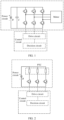
- the thermal management system controls the compressor and the PTC by using two independent drive apparatuses.
- a drive apparatus for controlling the compressor may be shown in FIG. 1
- a drive apparatus for controlling the PTC may be shown in FIG. 2 .
- the compressor requires one drive apparatus and the PTC requires another drive apparatus.
- the thermal management system of the electric vehicle needs to provide space for accommodating the two drive apparatuses. This results in a larger volume of the thermal management system.
- power of the compressor and power of the PTC are about 8 kilowatts, requiring high voltage power supply.
- each of a power circuit of the drive apparatus of the compressor and a power circuit of the drive apparatus of the PTC needs to use a high-voltage power supply harness and a matching connector, fuse, and the like, so that circuit costs are high.
- each of the drive apparatus of the compressor and the drive apparatus of the PTC requires high and low voltage isolation between the power circuit and a control circuit. This also increases costs of the thermal management system.
- An embodiment of this application provides a thermal management system.
- One driver may be used to drive a compressor and a heat emitting resistor to work, so that costs of the thermal management system can be reduced, and a volume of the thermal management system can be reduced.
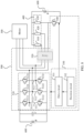
- FIG. 3A illustrates one example of the thermal management system.
- the thermal management system may include a motor 300.
- the motor 300 may rotate under driving of an alternating current, to drive a compressor of an air conditioner to work, so that the air conditioner can perform cooling or heating.
- the motor 300 may have N terminals. N is a positive integer greater than 1.
- the N terminals may receive alternating currents to drive the motor 300 to rotate.
- N may be 3, and the three terminals of the motor 300 are respectively a U-phase terminal, a V-phase terminal, and a W-phase terminal.
- the thermal management system may include a heat emitting resistor 400.
- the heat emitting resistor 400 may include N resistor branches, and the N resistor branches may be disposed in parallel. That is, different resistor branches in the N resistor branches are connected in parallel.
- a resistor in the N resistor branches may convert electric energy into thermal energy, to dissipate heat.
- the N resistor branches may include a resistor branch 410, a resistor branch 420, and a resistor branch 430.
- the N resistor branches may include a resistor branch 410, a resistor branch 420, a resistor branch 430, and a resistor branch 440.
- the heat emitting resistors 400 shown in FIG. 3A and FIG. 3B are merely examples for description of a quantity of resistor branches included in the thermal management system, and are not intended to impose limitations.
- the thermal management system may further include another quantity of resistor branches, for example, five resistor branches or six resistor branches, which are not listed one by one herein.
- a resistor on a resistor branch of the N resistor branches may be a PTC.
- one resistor may be disposed on one of the N resistor branches.
- a plurality of resistors may be disposed on one of the N resistor branches.
- a plurality of resistors on a same resistor branch may be disposed in series.
- the resistor branch 410 may be composed of a resistor 411 and a resistor 412 that are connected in series.
- the circuit branch 410 is provided with the resistor 411 and the resistor 412 that are disposed in series.
- a plurality of resistors on a same resistor branch may be disposed in parallel.
- the resistor branch 410 may be composed of a resistor 411 and a resistor 412 that are connected in parallel.
- the thermal management system may include a driver 500, which may be configured to control rotation of the motor 300 and control the heat emitting resistor 400 to emit heat.
- the driver 500 may include an inverter circuit 510.
- the inverter circuit 510 may include 2N switch elements, and every two switches may be disposed in series to form a bridge arm or an arm.
- the 2N switch elements may form N bridge arms. Different bridge arms in the inverter circuit 510 are disposed in parallel.
- One switch element on each bridge arm is coupled to a positive electrode of a battery 600, and the other switch element on the bridge arm is coupled to a negative electrode of the battery.
- one switch element on each bridge arm is closer to the positive electrode of the battery 600 and the other switch element on the bridge arm is closer to the negative electrode of the battery 600 in an electrical circuit.
- the switch element coupled to the positive electrode of the battery is a switch element on a positive electrode side of the battery, or a switch element close to the positive electrode of the battery in the electrical circuit.
- the switch element coupled to the negative electrode of the battery is a switch element on a negative electrode side of the battery, or a switch element close to the negative electrode of the battery in the electrical circuit.
- a switch element coupled to the positive electrode of the battery may be referred to as an upper bridge arm or an upper transistor of the bridge arm, and a switch element coupled to the negative electrode of the battery may be referred to as a lower bridge arm or a lower transistor of the bridge arm.
- a point between the two switch elements on each bridge arm may be referred to as a midpoint. That is, for a bridge arm, a midpoint is between a lower bridge arm and an upper bridge arm of the bridge arm.
- the switch element included in the inverter circuit 510 may be an element made of semiconductor silicon, for example, an insulated gate bipolar transistor (insulated gate bipolar transistor, IGBT), a metal-oxide-semiconductor field effect transistor (metal-oxide-semiconductor field effect transistor, MOSFET), and the like. Other examples are not listed one by one herein.
- the inverter circuit 510 may include three bridge arms, that is, the inverter circuit 510 may be a three-phase bridge circuit.
- the inverter circuit 510 may include a bridge arm 511, a bridge arm 512, and a bridge arm 513.
- the bridge arms are disposed in parallel.
- the bridge arm 511 is provided with a switch element 5111 and a switch element 5112.
- the switch element 5111 and the switch element 5112 are disposed in series, where the switch element 5111 is coupled to the positive electrode of the battery 600, and the switch element 5112 is coupled to the negative electrode of the battery 600. There is a midpoint 5113 between the switch element 5111 and the switch element 5112.
- the bridge arm 512 is provided with a switch element 5121 and a switch element 5122.
- the switch element 5121 and the switch element 5122 are disposed in series, where the switch element 5121 is coupled to the positive electrode of the battery 600, and the switch element 5122 is coupled to the negative electrode of the battery 600.
- the bridge arm 513 is provided with a switch element 5131 and a switch element 5132.
- the switch element 5131 and the switch element 5132 are disposed in series, where the switch element 5131 is coupled to the positive electrode of the battery 600, and the switch element 5132 is coupled to the negative electrode of the battery 600.
- the midpoint of each bridge arm may be connected to one of the N terminals of the motor 300.
- Midpoints of different bridge arms are connected to different terminals. That is, a bridge arm in the N bridge arms is in a one-to-one correspondence with a terminal in the N terminals, and the midpoint of each bridge arm may be connected to a terminal corresponding to the bridge arm.
- N is 3.
- the midpoint 5113 may be connected to one terminal of the motor 300
- the midpoint 5123 may be connected to another terminal of the motor 300
- the midpoint 5133 is connected to a remaining terminal of the motor 300.
- each bridge arm may be connected to one of the N resistor branches of the heat emitting resistor 400. Midpoints of different bridge arms are connected to different resistor branches.
- a bridge arm in the N bridge arms is in a one-to-one correspondence with a resistor branch in the N resistor branches, and the midpoint of each bridge arm may be connected to a resistor branch corresponding to the bridge arm.
- N is 3.
- the resistor branch 430 corresponds to the bridge arm 511, and the midpoint 5113 may be connected to the resistor branch 430.
- the resistor branch 420 corresponds to the bridge arm 512, and the midpoint 5123 may be connected to the resistor branch 420.
- the resistor branch 410 corresponds to the bridge arm 513, and the midpoint 5133 is connected to the resistor branch 410. It may be understood that the midpoint of each bridge arm is connected to one end of the corresponding resistor branch, and the other end of the resistor branch is directly connected to the battery 600.
- One end of the resistor branch connected to the midpoint of the bridge arm may be referred to as a D1 end, and one end directly connected to the battery may be referred to as a D2 end.
- the D2 end may be a positive electrode end of the resistor branch, that is, the resistor branch is directly connected to the positive electrode of the battery 600.
- the D1 end may be a negative electrode end of the resistor, that is, the resistor branch is indirectly connected to the negative electrode of the battery 600 through the midpoint of the bridge arm. Therefore, the related switch element in the inverter circuit 510 may be used as a low-side driver, to control a current output from the battery 600 to the resistor branch.
- the D1 end of the resistor may be a negative electrode end of the resistor branch
- the D2 end of the resistor may be a positive electrode end of the resistor branch. Therefore, the related switch element in the inverter circuit 510 may be used as a high-side driver, to control a current output from the battery 600 to the resistor branch.
- Each bridge arm of the inverter circuit 510 may further correspond to one switch element S (not shown).
- Each switch element S may be disposed on a connection line between a midpoint of a corresponding bridge arm and a resistor branch corresponding to the bridge arm.
- a switch element S When a switch element S is closed, a midpoint of a bridge arm corresponding to the switch element S is connected to a corresponding resistor branch corresponding to the bridge arm.
- a switch element S When a switch element S is open, a midpoint of a bridge arm corresponding to the switch element S is disconnected from a resistor branch corresponding to the bridge arm.
- the switch element S corresponding to each bridge arm of the inverter circuit 510 may be integrated into a repeater 520.
- the relay 520 may be disposed between the inverter circuit 510 and the heat emitting resistor 400, and may be configured to control connection or disconnection between the midpoint of each bridge arm in the inverter circuit 510 and the corresponding resistor branch in the heat emitting resistor 400.
- the relay 520 may be used as the switch element S corresponding to each of the N bridge arms of the inverter circuit 510, in other words, switch elements S corresponding to the N bridge arms may be integrated into the relay 520.
- one or more D1 ends of one or more resistor branches (for example, the resistor branch 430) in the heat emitting resistor 400 may further be directly connected to the battery 600, and a switch element 540 is disposed on a connection line between the D1 end and the battery 600.
- An electrode of the battery 600 connected to the one or more D1 ends of the one or more resistor branches is different from an electrode of the battery 600 connected to one or more D2 ends of the one or more resistor branches.
- the one or more D1 ends of the one or more resistor branches are connected to the negative electrode of the battery 600.
- the one or more D1 ends of the one or more resistor branches are connected to the positive electrode of the current 600.
- the driver 500 may further include a control circuit 530.
- the control circuit 530 may control an open state or a closed state of each switch element in the driver 500.
- Switch elements in the driver 500 may include the switch elements in the inverter circuit 510, the switch elements S between the inverter circuit 510 and the heat emitting resistor 400, and the switch element 540. Therefore, the control circuit 530 may control a current output from the battery 600 to the motor 300, and control a current output from the battery 600 to the heat emitting resistor 400. Controlling the open state or the closed state of the switch element may specifically mean controlling the switch element to be opened or closed, to disconnect or connect an electrical circuit in which the switch element is located.
- the control circuit 530 may include a drive circuit 531 and a decision circuit 532.
- the decision circuit 532 may generate a control instruction, and send the control instruction to the drive circuit 531.
- the drive circuit 531 may control the open state or the closed state of each switch element in the driver 500 based on the control instruction.
- the control instruction may be a low-voltage (for example, 5 V) logic signal.
- the drive circuit 531 may amplify the low-voltage logic signal into a high-voltage (for example, 15 V) signal that can drive the switch element to be opened or closed.
- the thermal management system may be in a mode in which the compressor works independently, that is, the motor 300 is independently controlled by the driver 500.
- the thermal management system may alternatively be in a mode in which the heat emitting resistor works independently, that is, the heat emitting resistor 400 is independently controlled by the driver 500.
- the thermal management system may be in the mode in which the compressor works independently.
- the energy efficiency ratio of the compressor is affected by the ambient temperature of the compressor. If the ambient temperature of the compressor is high, the energy efficiency ratio of the compressor may be greater than 1 (that is, 1:1), for example, may reach about 3 (that is, 3:1).
- a heat emitting principle of the resistor is to convert electric energy into thermal energy. Under an ideal condition, an energy efficiency ratio of the resistor may be 1. However, in actual application, limited by a line loss and the like, the energy efficiency ratio of the resistor is usually about 0.9.
- the energy efficiency ratio of the resistor can be set to a fixed value, for example, 0.9. In this embodiment of this application, when the energy efficiency ratio of the compressor is greater than the energy efficiency ratio of the resistor, the thermal management system may use the mode in which the compressor works independently, to reduce energy consumption.
- the control circuit 530 may determine whether a difference obtained by subtracting the energy efficiency ratio of the resistor from the energy efficiency ratio of the compressor is greater than or equal to a threshold Y1. If the difference is greater than or equal to the threshold Y1, the thermal management system may be controlled to enter the mode in which the compressor works independently.
- the threshold Y1 may be preset, for example, may be 0.1, or 0.2. Other examples are not listed one by one herein.
- the energy efficiency ratio of the compressor may be determined by the ambient temperature of the compressor. For example, a one-to-one correspondence between a temperature in a plurality of temperatures and an energy efficiency ratio in a plurality of energy efficiency ratios may be set.
- the control circuit 530 may obtain a current ambient temperature of the compressor, then determine a current energy efficiency ratio of the compressor based on the ambient temperature and the correspondence, and further determine whether the difference obtained by subtracting the energy efficiency ratio of the resistor from the current energy efficiency ratio of the compressor is greater than or equal to the threshold Y1. If the difference is greater than or equal to the threshold Y1, the thermal management system may be controlled to enter the mode in which the compressor works independently. For example, it may be understood that the compressor may have different energy efficiency ratios at a same ambient temperature due to different coolants. The energy efficiency ratio of the compressor may be determined based on the coolant of the compressor and the ambient temperature of the compressor.
- an energy efficiency ratio corresponding to each of a plurality of coolants at a plurality of different temperatures may be set or recorded.
- a coolant currently used by the compressor and the current ambient temperature are obtained, a current energy efficiency ratio of the compressor may be determined. Further, whether the difference obtained by subtracting the energy efficiency ratio of the resistor from the current energy efficiency ratio of the compressor is greater than or equal to the threshold Y1 may be determined. If the difference is greater than or equal to the threshold Y1, the thermal management system may be controlled to enter the mode in which the compressor works independently.
- the ambient temperature of the compressor described above refers to a temperature of an environment in which the compressor is located.
- a temperature sensor may be disposed near the compressor.
- the temperature sensor may send a collected temperature to the control circuit 530 in real time, or send a recently collected temperature to the control circuit 530 at a time interval T.
- the ambient temperature of the compressor may be a vehicle exterior ambient temperature of a vehicle in which the compressor is located.
- a vehicle exterior ambient temperature sensor of the vehicle may send a collected temperature to the control circuit 530 in real time, or send a recently collected temperature to the control circuit 530 at a time interval T.
- control circuit 530 may control the switch elements S between the inverter circuit 510 and the heat emitting resistor 400 to be opened and the switch element 540 to be opened.
- controlling the switch elements S between the inverter circuit 510 and the heat emitting resistor 400 to be opened may specifically mean controlling the relay 520 to be opened.
- the control circuit 530 may control closing and opening of each switch element in the inverter circuit 510, to change a direct current output by the battery 600 into an alternating current, so as to drive the motor 300 to rotate.
- a structure of the inverter circuit 510 shown in FIG. 4 is used as an example.
- a direction of a current output by the inverter circuit 510 to the motor 300 is a direction F 1.
- a direction of a current output from the inverter circuit 510 to the motor 300 is a direction F2.
- the direction F2 is opposite to the direction F1. In this way, the alternating current can be generated.
- the foregoing description is merely an example of a process in which the inverter circuit 510 converts the direct current into the alternating current, and is not intended to impose a limitation.
- Different switch elements in the inverter circuit 510 may be closed or opened under control of the control circuit 530, and another form of alternating current or a more complex alternating current may be generated.
- the control circuit 530 may be closed or opened under control of the control circuit 530, and another form of alternating current or a more complex alternating current may be generated.
- control circuit 530 may control, by controlling a duty cycle of the inverter circuit 510, a magnitude of the current output by the inverter circuit 510 to the motor 300, to control power of the motor 300.
- the duty cycle refers to a ratio of power-on duration in a pulse period to total duration of the pulse period.
- a pulse period refers to duration between a start moment of one power-on and a start moment of next power-on in a case of intermittent or periodic power-on.
- a current magnitude of the alternating current may be an average current value in a pulse period. Therefore, the magnitude of the alternating current can be controlled by controlling a value of the duty cycle.
- a current magnitude of a current output by the circuit may be set to 100 A.
- a duty cycle of the circuit may also be set to 25%, that is, in a pulse period, the circuit is powered on in 25% of duration, and is not powered on in remaining 75% of duration.
- a magnitude of a current output by the circuit is 25 A. In this way, an alternating current of any magnitude can be output to the motor 300 by controlling the duty cycle of the inverter circuit 510.
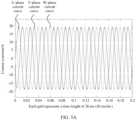
- control circuit 530 may output an alternating current shown in FIG. 5A to the motor 300 by controlling the inverter circuit 510, where a current amplitude is 19 A.
- the alternating current shown in FIG. 5A is merely an example for description.
- the control circuit 530 may control the inverter circuit 510 to input any expected current to the motor 300.
- For a manner of controlling the current magnitude refer to the foregoing descriptions. Details are not described herein again.
- each resistor in the heat emitting resistor 400 is not powered on, that is, the battery 600 does not input a current to each resistor in the heat emitting resistor.
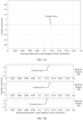
- a current at each resistor in the heat emitting resistor 400 is zero, which may be specifically shown in FIG. 5B .
- the thermal management system may be in the mode in which the heat emitting resistor works independently. If the ambient temperature of the compressor is low, the energy efficiency ratio of the compressor may be less than 1: 1 or even lower than an energy efficiency ratio of the resistor. For a manner of determining the energy efficiency ratio of the compressor and the energy efficiency ratio of the resistor, refer to the foregoing descriptions. Details are not described herein again. In this embodiment of this application, when the energy efficiency ratio of the compressor is less than the energy efficiency ratio of the resistor, the thermal management system may use the mode in which the heat emitting resistor works independently, to reduce energy consumption.
- control circuit 530 may determine whether a difference obtained by subtracting the energy efficiency ratio of the compressor from the energy efficiency ratio of the resistor is greater than or equal to a threshold Y2. If the difference is greater than or equal to the threshold Y2, the thermal management system may be controlled to enter the mode in which the heat emitting resistor works independently.
- the threshold Y2 may be preset, for example, may be 0.1, or 0.2. Other examples are not listed one by one herein.
- control circuit 530 may control the switch elements S between the inverter circuit 510 and the heat emitting resistor 400 to be closed, control all upper bridge arms (or lower bridge arms) in the inverter circuit 510 to be opened simultaneously, and control all lower bridge arms (or upper bridge arms) in the inverter circuit 510 to be closed simultaneously, to enable the battery 600 to be connected to the heat emitting resistor 400, so as to output a current to the heat emitting resistor 400, so that the heat emitting resistor generates heat.
- the inverter circuit 510 may be used as a low-side driver of the heat emitting resistor 400, to enable the heat emitting resistor 400 to be connected to the battery 600.
- the thermal management system when the thermal management system is in the mode in which the heat emitting resistor works independently, all the upper bridge arms in the inverter circuit 510 are in an open state, and the switch elements S between the inverter circuit 510 and the heat emitting resistor 400 are in a closed state. All the lower bridge arms in the inverter circuit 510 are closed simultaneously, so that a voltage difference between different terminals of the motor 300 is zero, and no current input is generated. Simultaneous closing of all the lower bridge arms in the inverter circuit 510 enables the resistor in the heat emitting resistor 400 to be connected to the battery 600, to obtain electric energy from the battery 600, and further generate heat.
- the control circuit 530 may control a duty cycle of the lower bridge arm of the inverter circuit 510, to control a magnitude of a current input to the heat emitting resistor 400.
- the control circuit 530 needs to control all the lower bridge arms of the inverter circuit 510 to be closed simultaneously, then control all the lower bridge arms of the inverter circuit 510 to be opened simultaneously, then control all the lower bridge arms of the inverter circuit 510 to be closed simultaneously, and so on. In this way, the voltage difference between different terminals of the motor 300 is always zero while the current input to the heat emitting resistor 400 is controlled.
- the inverter circuit 510 may be used as the low-side driver of the heat emitting resistor 400 is described.
- the switch element 5111, the switch element 5121 and the switch element 5131 are all in the open state, and the relay 520 is in the closed state.
- the switch element 5112, the switch element 5122, and the switch element 5132 are closed simultaneously, or alternately closed simultaneously and opened simultaneously, so that the heat emitting resistor 400 can obtain electric energy from the battery 600, and further generate heat.
- the inverter circuit 510 may be used as a high-side driver of the heat emitting resistor 400, to enable the heat emitting resistor 400 to be connected to the battery 600.
- the thermal management system when the thermal management system is in the mode in which the heat emitting resistor works independently, all the lower bridge arms in the inverter circuit 510 are in an open state, and the switch elements S between the inverter circuit 510 and the heat emitting resistor 400 are in a closed state. All the upper bridge arms in the inverter circuit 510 are closed simultaneously, so that a voltage difference between different terminals of the motor 300 is zero, and no current input is generated. Simultaneous closing of all the upper bridge arms in the inverter circuit 510 enables the resistor in the heat emitting resistor 400 to be connected to the battery 600, to obtain electric energy from the battery 600, and further generate heat.
- the control circuit 530 may control a duty cycle of the upper bridge arm of the inverter circuit 510, to control a magnitude of a current input to the heat emitting resistor 400.
- the control circuit 530 needs to control all the upper bridge arms of the inverter circuit 510 to be closed simultaneously, then control all the upper bridge arms of the inverter circuit 510 to be opened simultaneously, then control all the upper bridge arms of the inverter circuit 510 to be closed simultaneously, and so on. In this way, the voltage difference between different terminals of the motor 300 is always zero while the current input to the heat emitting resistor 400 is controlled.
- an input current of the motor 300 may be zero.
- an input current of each resistor in the heat emitting resistor 400 is not zero.
- the thermal management system may drive the compressor to work and drive the heat emitting resistor to work by using a single driver, so that space of the thermal management system can be saved, and costs of the thermal management system can be reduced.
- the thermal management system may alternatively be in a mode in which the compressor and the heat emitting resistor work simultaneously, that is, the driver 500 controls the motor 300 and the heat emitting resistor 400 to work simultaneously.
- the thermal management system may use the mode in which the compressor and the heat emitting resistor work simultaneously.
- a range or an interval may be preset, for example, an interval (-0.1, 0.1) or an interval (-0.2, 0.2). Other examples are not listed one by one herein.
- the thermal management system may enter the mode in which the compressor and the heat emitting resistor work simultaneously.
- the switch elements S or the relay 520 between the inverter circuit 510 and the heat emitting resistor 400 are/is in a closed state.
- control circuit 530 may control closing and opening of each switch element in the inverter circuit 510, to change a direct current output by the battery 600 into an alternating current, so as to drive the motor 300 to rotate.
- control circuit 530 may control closing and opening of each switch element in the inverter circuit 510, to change a direct current output by the battery 600 into an alternating current, so as to drive the motor 300 to rotate.
- control circuit 530 may control the switch element 540 to be closed, so that the one or more resistor branches may be connected to the battery 600, to obtain electric energy and generate heat.
- control circuit 530 may further adjust a duty cycle of the switch element 540, to adjust magnitudes of input currents of the one or more resistor branches.
- the one or more resistor branches may be some of the N resistor branches.
- the one or more resistor branches may be specifically one resistor branch.
- only one switch element 540 may be disposed to implement driving of the resistor branch. In this way, electronic components in the thermal management system are further saved, and the costs of the thermal management system are further reduced.
- the one or more resistor branches may be the resistor branch 430, and the switch element 540 is a switch element corresponding to the resistor branch 430.
- the one or more resistor branches may be specifically two or more resistor branches.
- a switch element 540 may be disposed between a D1 end of each of the two or more resistor branches and the battery 600, to separately drive each of the two or more resistor branches.
- the one or more resistor branches may be specifically two or more resistor branches.
- One switch element 540 may be disposed between D1 ends of the two or more resistor branches and the battery 600. That is, the two or more resistor branches may be driven simultaneously by using one switch element 540.
- the one or more resistor branches may be set as the resistor branch 430.
- Input currents of the resistor branch 430 and other resistor branches may be shown in FIG. 9B .
- the resistor branch 430 may obtain the input current as shown in FIG. 9B , and the input currents of the other resistor branches are zero.
- the thermal management system may first enter a shutdown state and maintain the shutdown state for a specific duration T 1.
- the duration T1 may be specifically about 500 ms, for example, may be 500 ms, 550 ms, or 450 ms.
- Other examples are not listed one by one herein. That is, before the relay is closed, the thermal management system is shut down for about 500 ms, and then the relay is closed.
- the thermal management system may switch from the mode in which the compressor and the heat emitting resistor work simultaneously to the mode in which the heat emitting resistor works independently. It can be learned from the foregoing discussion that, in the mode in which the heat emitting resistor works independently, the relay needs to be closed, so that the inverter circuit 510 is used as a drive circuit of the heat emitting resistor 400. Therefore, the thermal management system may first enter the shutdown state, so that the compressor and the heat emitting resistor 400 completely stop working for the duration T1. Then, the relay is closed, so that the thermal management system enters the mode in which the heat emitting resistor works independently.
- the thermal management system may switch from the mode in which the compressor works independently to the mode in which the heat emitting resistor works independently. Therefore, the thermal management system may first enter the shutdown state, so that the compressor completely stops working for the duration T1. Then, the relay is closed, so that the thermal management system enters the mode in which the heat emitting resistor works independently.
- the thermal management system is a large time inertia system, and the shutdown state occupies about 500 ms. This does not affect heating of the vehicle greatly.
- the thermal management system provided in embodiments of this application can control, by using a single driver, the compressor and the heat emitting resistor to work.
- This reduces use of the electronic components and lines, reduces the costs of the thermal management system, and saves the space of the thermal management system, so that the volume of the thermal management system can be designed to be smaller.
- no additional high and low voltage separation is required, and this further reduces the costs of the thermal management system.
- a single electronic control unit electronic control unit, ECU
- the ECU may be used as the driver 500.
Landscapes
- Engineering & Computer Science (AREA)
- Mechanical Engineering (AREA)
- Power Engineering (AREA)
- Transportation (AREA)
- Chemical & Material Sciences (AREA)
- Electrochemistry (AREA)
- Chemical Kinetics & Catalysis (AREA)
- Manufacturing & Machinery (AREA)
- General Chemical & Material Sciences (AREA)
- Sustainable Development (AREA)
- Sustainable Energy (AREA)
- Life Sciences & Earth Sciences (AREA)
- Physics & Mathematics (AREA)
- Thermal Sciences (AREA)
- Combustion & Propulsion (AREA)
- Electromagnetism (AREA)
- Inverter Devices (AREA)
- Air-Conditioning For Vehicles (AREA)
- Electric Propulsion And Braking For Vehicles (AREA)
Abstract
Description
- This application relates to the field of electric vehicles, and in particular, to a vehicle thermal management system, a drive apparatus, and an electric vehicle.
- For ride comfort of a vehicle, safety of the vehicle, and exertion of related performance of the vehicle, a thermal management system (thermal management system, TMS) is needed to control temperatures of components such as a passenger compartment and a drive system (for example, an engine of a conventional fuel vehicle and a battery of an electric vehicle) of the vehicle. Therefore, the thermal management system is an important system of the vehicle.
- Especially for an electric vehicle, a thermal management system is more important and demanding. Generally, the thermal management system of the electric vehicle needs to control temperatures of a battery (for example, a power battery of the electric vehicle), an electric drive unit (for example, a drive motor that powers running of the electric vehicle by using electric energy provided by the power battery), an on-board charger, a passenger compartment, and the like. Specifically, at a high temperature, it is necessary to dissipate heat for the battery, the electric drive unit, the on-board charging unit, the passenger compartment, and the like. At a low temperature, the thermal management system needs to heat the battery, the passenger compartment, and the like.
- At present, the thermal management system of the electric vehicle is expensive and bulky.
- Embodiments of this application provide a vehicle thermal management system, a drive apparatus, and an electric vehicle. A compressor of an air conditioner and a heat emitting resistor may be driven by using a single drive apparatus. This may reduce costs of a thermal management system of an electric vehicle.
- According to a first aspect, an embodiment of this application provides a thermal management system for temperature control of an electric vehicle. The thermal management system includes: a motor, N resistor branches, and a driver configured to drive the motor and resistors on the N resistor branches to work, where N is a positive integer greater than 1. The motor is configured to rotate under an action of an alternating current, to drive the compressor of the air conditioner to work. The driver includes a control circuit and an inverter circuit. Each of N bridge arms of the inverter circuit is connected to one terminal of the motor, and different bridge arms are connected to different terminals. A midpoint of each of the N bridge arms is connected to one of the N resistor branches, and different bridge arms are connected to different resistor branches. A first switch is coupled between the midpoint of each bridge arm and the resistor branch connected to the bridge arm. The control circuit is configured to: control all first switches corresponding to the N bridge arms to be in an open state, and control the inverter circuit to output an alternating current to the motor. The control circuit is configured to: control all the first switches corresponding to the N bridge arms to be in a closed state, and control the inverter circuit to output currents to the N resistor branches.
- In other words, the driver in the thermal management system provided in this embodiment of this application may be configured to drive the compressor of the air conditioner to work, and may be configured to drive a heat emitting resistor to work. Therefore, there is no need to separately set one set of drive apparatus for the compressor and the heat emitting resistor. This reduces costs of the thermal management system, saves space of the thermal management system, and reduces a volume of the thermal management system.
- In a possible implementation, when a difference obtained by subtracting an energy efficiency ratio of the resistor from an energy efficiency ratio of the compressor is greater than or equal to a first threshold, the driver is configured to independently drive the motor to work, to drive the compressor.
- That is, in this implementation, when the energy efficiency ratio of the compressor is greater than the energy efficiency ratio of the resistor, the driver may drive the compressor to work, without driving the resistor to work, to reduce energy consumption.
- In a possible implementation, when the difference obtained by subtracting the energy efficiency ratio of the compressor from the energy efficiency ratio of the resistor is greater than or equal to a second threshold, the driver is configured to independently drive the resistor on the resistor branch to work.
- That is, when the energy efficiency ratio of the resistor is greater than the energy efficiency ratio of the compressor, the driver may drive the resistor for heating, without driving the compressor for heating, to reduce energy consumption.
- In a possible implementation, the driver further includes a second switch disposed between a first resistor branch and a battery, and the first resistor branch is one or more of the N resistor branches. The control circuit is configured to: control all the first switches corresponding to the N bridge arms to be in the open state, and control the second switch to enter the closed state, so that a resistor on the first resistor branch may obtain a current from the battery.
- That is, in this implementation, by disposing the second switch, when all the first switches corresponding to the N bridge arms are open, the battery may supply power to one or more of the N resistor branches. In this way, simultaneous working of the compressor and the resistor can be controlled by the single driver.
- In a possible implementation, the second switch includes one or more switches, and the one or more switches are in a one-to-one correspondence with the one or more resistor branches.
- That is, one second switch may be disposed for each of the one or more resistor branches, so that a quantity of resistors working simultaneously with the compressor can be adjusted.
- In a possible implementation, the second switch is disposed between the first resistor and a negative electrode of the battery.
- That is, the second switch can be used as a low-side driver of the first resistor. This can improve security of the thermal management system, and further reduce the costs of the thermal management system.
- In a possible implementation, when the difference between the energy efficiency ratio of the compressor and the energy efficiency ratio of the resistor falls within a preset range, the driver is configured to drive the compressor and one or more resistors on the one or more resistor branches to work simultaneously.
- That is, in this implementation, when the energy efficiency ratio of the compressor is almost equal to the energy efficiency ratio of the resistor, both the air conditioner and the resistor may be used for heating.
- In a possible implementation, a switch element on one side of the midpoint of the bridge arm is a third switch element coupled to a first electrode of the battery, and a switch element on the other side of the midpoint of the bridge arm is a fourth switch element coupled to a second electrode of the battery. The control circuit is configured to: control third switch elements on the N bridge arms to be opened simultaneously, and control fourth switch elements on the N bridge arms to be closed simultaneously, so that the inverter circuit outputs the currents to the N resistor branches.
- That is, in this implementation, in the inverter circuit, the switch element on one side of each of the bridge arms is controlled to be opened simultaneously, and a switch element on the other side of each of the bridge arms is controlled to be closed simultaneously, so that the inverter circuit may be used as a power circuit of the resistor branch to output a current to the resistor branch.
- In a possible implementation, the first electrode is a positive electrode of the battery, and the second electrode is the negative electrode of the battery. Alternatively, the first electrode is the negative electrode of the battery, and the second electrode is a positive electrode of the battery.
- That is, in this implementation, lower bridge arms of the inverter circuit may be used as low-side drivers of the N resistor branches, or upper bridge arms of the inverter circuit may be used as high-side drivers of the N resistor branches. In this way, the N resistor branches can be flexibly controlled.
- In a possible implementation, the control circuit is configured to control duration in which the fourth switch elements on the N bridge arms are in the closed state in a single pulse period, to control magnitudes of the currents output by the inverter circuit to the N resistors.
- That is, in this implementation, duty cycles of the fourth switch elements may be controlled to control the magnitudes of the currents output to the N resistor branches, to flexibly control power of the N resistor branches.
- In a possible implementation, the driver includes a relay, and the relay is used as the first switch corresponding to each of the N bridge arms; or the first switches corresponding to one or more of the N bridge arms are circuit breakers; or the first switches corresponding to one or more of the N bridge arms are insulated gate bipolar transistors IGBTs or metal oxide semiconductor field effect transistors MOSFETs.
- That is, in this implementation, the switch elements between the inverter circuit and the heat emitting resistor may include a plurality of options, so that the driver can be flexibly designed.
- In a possible implementation, the resistor in the N resistor branches is a positive temperature coefficient PTC resistor.
- A resistance value of the PTC increases with an increase of a temperature. This has high security. In this implementation, the PTC is used as the heat emitting resistor, so that security of the thermal management system can be improved.
- According to a second aspect, an embodiment of this application provides a drive apparatus. The drive apparatus includes a control circuit and an inverter circuit having N bridge arms, where N is a positive integer greater than 1. A midpoint of each of the N bridge arms is configured to connect to one terminal in a motor, and different bridge arms in the N bridge arms are connected to different terminals. The motor is configured to drive, when rotating, a compressor of an air conditioner to work, to enable the air conditioner to perform heating or cooling. The midpoint of each of the N bridge arms is configured to connect to one of N resistor branches, and different bridge arms in the N bridge arms are connected to different resistor branches. A first switch is coupled between the midpoint of each of the N bridge arms and the resistor branch connected to each bridge arm. One or more resistors are disposed on each of the N resistor branches, and the resistor is configured to convert electric energy into thermal energy. The control circuit is configured to: control all first switches corresponding to the N bridge arms to be in an open state, and control the inverter circuit to output an alternating current to the motor. The control circuit is configured to: control all the first switches corresponding to the N bridge arms to be in a closed state, and control the inverter circuit to output currents to the N resistor branches.
- In a possible implementation, when a difference obtained by subtracting an energy efficiency ratio of the resistor from an energy efficiency ratio of the compressor is greater than or equal to a first threshold, the control circuit is configured to: control all the first switches corresponding to the N bridge arms to be in the open state, and control the inverter circuit to output the alternating current to the motor.
- In a possible implementation, when a difference obtained by subtracting the energy efficiency ratio of the compressor from the energy efficiency ratio of the resistor is greater than or equal to a second threshold, the control circuit is configured to: control all the first switches corresponding to the N bridge arms to be in the closed state, and control the inverter circuit to output the currents to the N resistor branches.
- In a possible implementation, the drive apparatus further includes a second switch disposed between a first resistor branch and a battery, and the first resistor branch is one or more of the N resistor branches. The control circuit is configured to: control all the first switches corresponding to the N bridge arms to be in the open state, and control the second switch to enter the closed state, so that a resistor on the first resistor branch obtains a current from the battery.
- In a possible implementation, the second switch includes one or more switches, and the one or more switches are in a one-to-one correspondence with the one or more resistor branches.
- In a possible implementation, the second switch is disposed between the first resistor branch and a negative electrode of the battery.
- In a possible implementation, when a difference between the energy efficiency ratio of the compressor and the energy efficiency ratio of the resistor falls within a preset range, the control circuit is configured to: control all the first switches corresponding to the N bridge arms to be in the open state, and control the second switch to enter the closed state, so that the resistor on the first resistor branch obtains the current from the battery.
- In a possible implementation, a switch element on one side of the midpoint of the bridge arm is a third switch element coupled to a first electrode of the battery, and a switch element on the other side of the midpoint of the bridge arm is a fourth switch element coupled to a second electrode of the battery. The control circuit is configured to: control third switch elements on the N bridge arms to be opened simultaneously, and control fourth switch elements on the N bridge arms to be closed simultaneously, so that the inverter circuit outputs the currents to the N resistor branches.
- In a possible implementation, the first electrode is a positive electrode of the battery, and the second electrode is the negative electrode of the battery. Alternatively, the first electrode is the negative electrode of the battery, and the second electrode is a positive electrode of the battery.
- In a possible implementation, the control circuit is configured to control duration in which the fourth switch elements on the N bridge arms are in the closed state in a single pulse period, to control magnitudes of the currents output by the inverter circuit to the N resistor branches.
- In a possible implementation, the drive apparatus includes a relay, and the relay is used as the first switch corresponding to each of the N bridge arms; or the first switches corresponding to one or more of the N bridge arms are circuit breakers; or the first switches corresponding to one or more of the N bridge arms are insulated gate bipolar transistors IGBTs or metal oxide semiconductor field effect transistors MOSFETs.
- It may be understood that the drive apparatus provided in the second aspect may be configured to drive the compressor and the motor of the thermal management system provided in the first aspect. For beneficial effect of the drive apparatus, refer to the foregoing descriptions of beneficial effect of the thermal management system provided in the first aspect.
- According to a third aspect, an embodiment of this application provides an electric vehicle, including the thermal management system provided in the first aspect or the drive apparatus provided in the second aspect.
- According to the thermal management system and the drive apparatus provided in embodiments of this application, a single drive apparatus or driver may be used to drive the compressor and the heat emitting resistor. This reduces use of electronic components and lines, reduces the costs of the thermal management system, and saves the space of the thermal management system, so that the volume of the thermal management system can be designed to be smaller. In addition, no additional high and low voltage separation is required, and this further reduces the costs of the thermal management system.
-
-
FIG. 1 is a schematic diagram of a structure of a drive apparatus for driving a compressor to work; -
FIG. 2 is a schematic diagram of a structure of a drive apparatus for driving a PTC to work; -
FIG. 3A is a schematic diagram of a structure of a thermal management system according to an embodiment of this application; -
FIG. 3B is a schematic diagram of a structure of a thermal management system according to an embodiment of this application; -
FIG. 3C is a schematic diagram of a structure of a resistor branch shown inFIG. 3A orFIG. 3B ; -
FIG. 3D is a schematic diagram of a structure of a resistor branch shown inFIG. 3A orFIG. 3B ; -
FIG. 4 is a schematic diagram of a working principle of a thermal management system in an independent working mode of a compressor according to an embodiment of this application; -
FIG. 5A is a simulation diagram of an input current of a motor of a compressor in a mode in which the compressor works independently; -
FIG. 5B is a simulation diagram of an input current of a heat emitting resistor in a mode in which a compressor works independently; -
FIG. 6 is a schematic diagram of a working principle of a thermal management system in a mode in which a heat emitting resistor works independently according to an embodiment of this application; -
FIG. 7A is a simulation diagram of an input current of a motor of a compressor in a mode in which a heat emitting resistor works independently; -
FIG. 7B is a simulation diagram of an input current of each resistor in a heat emitting resistor in a mode in which the heat emitting resistor works independently; -
FIG. 8 is a schematic diagram of a working principle of a thermal management system in a mode in which a compressor and a heat emitting resistor work simultaneously according to an embodiment of this application; -
FIG. 9A is a simulation diagram of an input current of a motor of a compressor in a mode in which the compressor and a heat emitting resistor work simultaneously; -
FIG. 9B is a simulation diagram of an input current of each resistor in a heat emitting resistor in a mode in which a compressor and the heat emitting resistor work simultaneously; and -
FIG. 10 is a schematic diagram of a structure of a thermal management system according to an embodiment of this application. - The following describes technical solutions of embodiments in this application with reference to accompanying drawings.
- In general, a battery (for example, a power battery) of an electric vehicle needs to work within a suitable temperature range. If a temperature of the battery is excessively high, a service life of the battery is affected and a security risk may be caused. If a temperature of the battery is excessively low, an available capacity of the battery may be greatly attenuated. This limits performance of the battery. Therefore, when the battery works, the temperature of the battery needs to be maintained within a specific range. In addition, unlike a conventional fuel vehicle, which may heat a passenger compartment by using cooling water of an engine, an electric vehicle needs to heat a passenger compartment and another component by using electric energy of a battery.
- In view of the above reasons, a thermal management system of the electric vehicle is more important and demanding than a thermal management system of the conventional fuel vehicle.
- Generally, the thermal management system of the electric vehicle includes a water loop, a coolant circuit, a temperature and pressure sensor, a water valve, a solenoid valve, a water pump, a compressor of an air conditioner, an air conditioning box, a positive temperature coefficient (positive temperature coefficient, PTC) resistor, and the like, to heat or cool the battery and the passenger compartment of the electric vehicle, and cool an electric drive unit, an on-board charger, and the like.
- In this embodiment of this application, the electric vehicle may be a pure electric vehicle (pure electric vehicle/battery electric vehicle, pure EV/battery EV), a hybrid electric vehicle (hybrid electric vehicle, HEV), a range extended electric vehicle (range extended electric vehicle, REEV), a plug-in hybrid electric vehicle (plug-in hybrid electric vehicle, PHEV), a new energy vehicle (new energy vehicle, NEV), or the like.
- The compressor of the air conditioner may be referred to as a compressor for short. It can be understood that, generally speaking, an energy efficiency ratio of the compressor is high, and may reach about 3: 1. In other words, the compressor may transfer about 3 kilowatts of heat while consuming 1 kilowatt of electricity. However, at a lower ambient temperature, the energy efficiency ratio of the compressor is decreased. For example, an energy efficiency ratio of a compressor using R134A refrigerant as a coolant is only about 1:1 at an ambient temperature of about minus 7°C. As the ambient temperature decreases, the energy efficiency ratio of the compressor is further decreased. At an extremely low ambient temperature, the coolant of the compressor may not be able to build up pressure. Specifically, temperatures of a condenser and a reservoir of the compressor are so low that there is not enough pressure to feed a liquid coolant into an evaporator when the compressor is started.
- The PTC may be configured to heat water in the water loop, so that other components can be heated by using the water loop. A resistance value of the PTC increases with an increase of a temperature. This has high security. At an extremely low ambient temperature, the thermal management system may heat the battery and the like by using the PTC. At a lower ambient temperature, the compressor and the PTC can be used simultaneously to heat the battery and the like. At a high ambient temperature, the compressor can be used independently to heat or cool the battery and the like.
- It may be understood that the extremely low ambient temperature, the low ambient temperature, and the high ambient temperature respectively correspond to different temperature ranges. For compressors using different coolants, temperature ranges corresponding to the extremely low ambient temperature may be different, temperature ranges corresponding to the low ambient temperature may also be different, and temperature ranges corresponding to the high ambient temperature may also be different. For example, for the compressor using R134A refrigerant as the coolant, the extremely low ambient temperature may be below minus 15°C, the low ambient temperature may range from minus 15°C to minus 7°C, and the high ambient temperature may be above minus 7°C.
- In a solution, the thermal management system controls the compressor and the PTC by using two independent drive apparatuses. A drive apparatus for controlling the compressor may be shown in
FIG. 1 , and a drive apparatus for controlling the PTC may be shown inFIG. 2 . In this solution, the compressor requires one drive apparatus and the PTC requires another drive apparatus. The thermal management system of the electric vehicle needs to provide space for accommodating the two drive apparatuses. This results in a larger volume of the thermal management system. Moreover, power of the compressor and power of the PTC are about 8 kilowatts, requiring high voltage power supply. In other words, each of a power circuit of the drive apparatus of the compressor and a power circuit of the drive apparatus of the PTC needs to use a high-voltage power supply harness and a matching connector, fuse, and the like, so that circuit costs are high. In addition, each of the drive apparatus of the compressor and the drive apparatus of the PTC requires high and low voltage isolation between the power circuit and a control circuit. This also increases costs of the thermal management system. - An embodiment of this application provides a thermal management system. One driver may be used to drive a compressor and a heat emitting resistor to work, so that costs of the thermal management system can be reduced, and a volume of the thermal management system can be reduced.
-
FIG. 3A illustrates one example of the thermal management system. In this example, the thermal management system may include amotor 300. Themotor 300 may rotate under driving of an alternating current, to drive a compressor of an air conditioner to work, so that the air conditioner can perform cooling or heating. Themotor 300 may have N terminals. N is a positive integer greater than 1. The N terminals may receive alternating currents to drive themotor 300 to rotate. For example, N may be 3, and the three terminals of themotor 300 are respectively a U-phase terminal, a V-phase terminal, and a W-phase terminal. - The thermal management system may include a
heat emitting resistor 400. Theheat emitting resistor 400 may include N resistor branches, and the N resistor branches may be disposed in parallel. That is, different resistor branches in the N resistor branches are connected in parallel. When a power supply is connected, a resistor in the N resistor branches may convert electric energy into thermal energy, to dissipate heat. For example, as shown inFIG. 3A , the N resistor branches may include aresistor branch 410, aresistor branch 420, and aresistor branch 430. For example, as shown inFIG. 3B , the N resistor branches may include aresistor branch 410, aresistor branch 420, aresistor branch 430, and aresistor branch 440. It may be understood that, theheat emitting resistors 400 shown inFIG. 3A andFIG. 3B are merely examples for description of a quantity of resistor branches included in the thermal management system, and are not intended to impose limitations. The thermal management system may further include another quantity of resistor branches, for example, five resistor branches or six resistor branches, which are not listed one by one herein. - In some embodiments, a resistor on a resistor branch of the N resistor branches may be a PTC.
- In some embodiments, one resistor may be disposed on one of the N resistor branches.
- In some embodiments, a plurality of resistors may be disposed on one of the N resistor branches. For example, a plurality of resistors on a same resistor branch may be disposed in series. In an example, as shown in
FIG. 3C , theresistor branch 410 may be composed of aresistor 411 and aresistor 412 that are connected in series. In other words, thecircuit branch 410 is provided with theresistor 411 and theresistor 412 that are disposed in series. For example, a plurality of resistors on a same resistor branch may be disposed in parallel. In an example, as shown inFIG. 3D , theresistor branch 410 may be composed of aresistor 411 and aresistor 412 that are connected in parallel. - The thermal management system may include a
driver 500, which may be configured to control rotation of themotor 300 and control theheat emitting resistor 400 to emit heat. Thedriver 500 may include aninverter circuit 510. Theinverter circuit 510 may include 2N switch elements, and every two switches may be disposed in series to form a bridge arm or an arm. The 2N switch elements may form N bridge arms. Different bridge arms in theinverter circuit 510 are disposed in parallel. One switch element on each bridge arm is coupled to a positive electrode of abattery 600, and the other switch element on the bridge arm is coupled to a negative electrode of the battery. In other words, one switch element on each bridge arm is closer to the positive electrode of thebattery 600 and the other switch element on the bridge arm is closer to the negative electrode of thebattery 600 in an electrical circuit. The switch element coupled to the positive electrode of the battery is a switch element on a positive electrode side of the battery, or a switch element close to the positive electrode of the battery in the electrical circuit. The switch element coupled to the negative electrode of the battery is a switch element on a negative electrode side of the battery, or a switch element close to the negative electrode of the battery in the electrical circuit. For a bridge arm, a switch element coupled to the positive electrode of the battery may be referred to as an upper bridge arm or an upper transistor of the bridge arm, and a switch element coupled to the negative electrode of the battery may be referred to as a lower bridge arm or a lower transistor of the bridge arm. A point between the two switch elements on each bridge arm may be referred to as a midpoint. That is, for a bridge arm, a midpoint is between a lower bridge arm and an upper bridge arm of the bridge arm. - In some embodiments, the switch element included in the
inverter circuit 510 may be an element made of semiconductor silicon, for example, an insulated gate bipolar transistor (insulated gate bipolar transistor, IGBT), a metal-oxide-semiconductor field effect transistor (metal-oxide-semiconductor field effect transistor, MOSFET), and the like. Other examples are not listed one by one herein. - In some embodiments, as shown in
FIG. 3A , theinverter circuit 510 may include three bridge arms, that is, theinverter circuit 510 may be a three-phase bridge circuit. Specifically, theinverter circuit 510 may include abridge arm 511, abridge arm 512, and abridge arm 513. The bridge arms are disposed in parallel. Thebridge arm 511 is provided with aswitch element 5111 and aswitch element 5112. Theswitch element 5111 and theswitch element 5112 are disposed in series, where theswitch element 5111 is coupled to the positive electrode of thebattery 600, and theswitch element 5112 is coupled to the negative electrode of thebattery 600. There is amidpoint 5113 between theswitch element 5111 and theswitch element 5112. Thebridge arm 512 is provided with aswitch element 5121 and aswitch element 5122. Theswitch element 5121 and theswitch element 5122 are disposed in series, where theswitch element 5121 is coupled to the positive electrode of thebattery 600, and theswitch element 5122 is coupled to the negative electrode of thebattery 600. There is amidpoint 5123 between theswitch element 5121 and theswitch element 5122. Thebridge arm 513 is provided with aswitch element 5131 and aswitch element 5132. Theswitch element 5131 and theswitch element 5132 are disposed in series, where theswitch element 5131 is coupled to the positive electrode of thebattery 600, and theswitch element 5132 is coupled to the negative electrode of thebattery 600. There is amidpoint 5133 between theswitch element 5131 and theswitch element 5132. - Next, a connection manner between the
inverter circuit 510 and themotor 300 is described. - Refer to
FIG. 3A . The midpoint of each bridge arm may be connected to one of the N terminals of themotor 300. Midpoints of different bridge arms are connected to different terminals. That is, a bridge arm in the N bridge arms is in a one-to-one correspondence with a terminal in the N terminals, and the midpoint of each bridge arm may be connected to a terminal corresponding to the bridge arm. For example, N is 3. As shown inFIG. 3A , themidpoint 5113 may be connected to one terminal of themotor 300, themidpoint 5123 may be connected to another terminal of themotor 300, and themidpoint 5133 is connected to a remaining terminal of themotor 300. - Next, a connection manner between the
inverter circuit 510 and theheat emitting resistor 400 is described. - Refer to
FIG. 3A . The midpoint of each bridge arm may be connected to one of the N resistor branches of theheat emitting resistor 400. Midpoints of different bridge arms are connected to different resistor branches. In other words, a bridge arm in the N bridge arms is in a one-to-one correspondence with a resistor branch in the N resistor branches, and the midpoint of each bridge arm may be connected to a resistor branch corresponding to the bridge arm. For example, N is 3. As shown inFIG. 3A , theresistor branch 430 corresponds to thebridge arm 511, and themidpoint 5113 may be connected to theresistor branch 430. Theresistor branch 420 corresponds to thebridge arm 512, and themidpoint 5123 may be connected to theresistor branch 420. Theresistor branch 410 corresponds to thebridge arm 513, and themidpoint 5133 is connected to theresistor branch 410. It may be understood that the midpoint of each bridge arm is connected to one end of the corresponding resistor branch, and the other end of the resistor branch is directly connected to thebattery 600. One end of the resistor branch connected to the midpoint of the bridge arm may be referred to as a D1 end, and one end directly connected to the battery may be referred to as a D2 end. For example, the D2 end may be a positive electrode end of the resistor branch, that is, the resistor branch is directly connected to the positive electrode of thebattery 600. The D1 end may be a negative electrode end of the resistor, that is, the resistor branch is indirectly connected to the negative electrode of thebattery 600 through the midpoint of the bridge arm. Therefore, the related switch element in theinverter circuit 510 may be used as a low-side driver, to control a current output from thebattery 600 to the resistor branch. For example, the D1 end of the resistor may be a negative electrode end of the resistor branch, and the D2 end of the resistor may be a positive electrode end of the resistor branch. Therefore, the related switch element in theinverter circuit 510 may be used as a high-side driver, to control a current output from thebattery 600 to the resistor branch. - Each bridge arm of the
inverter circuit 510 may further correspond to one switch element S (not shown). Each switch element S may be disposed on a connection line between a midpoint of a corresponding bridge arm and a resistor branch corresponding to the bridge arm. When a switch element S is closed, a midpoint of a bridge arm corresponding to the switch element S is connected to a corresponding resistor branch corresponding to the bridge arm. When a switch element S is open, a midpoint of a bridge arm corresponding to the switch element S is disconnected from a resistor branch corresponding to the bridge arm. For example, the switch element S corresponding to each bridge arm of theinverter circuit 510 may be integrated into arepeater 520. In other words, therelay 520 may be disposed between theinverter circuit 510 and theheat emitting resistor 400, and may be configured to control connection or disconnection between the midpoint of each bridge arm in theinverter circuit 510 and the corresponding resistor branch in theheat emitting resistor 400. In other words, therelay 520 may be used as the switch element S corresponding to each of the N bridge arms of theinverter circuit 510, in other words, switch elements S corresponding to the N bridge arms may be integrated into therelay 520. - In some embodiments, as shown in
FIG. 3A , one or more D1 ends of one or more resistor branches (for example, the resistor branch 430) in theheat emitting resistor 400 may further be directly connected to thebattery 600, and aswitch element 540 is disposed on a connection line between the D1 end and thebattery 600. An electrode of thebattery 600 connected to the one or more D1 ends of the one or more resistor branches is different from an electrode of thebattery 600 connected to one or more D2 ends of the one or more resistor branches. When the one or more D2 ends of the one or more resistor branches are connected to the positive electrode of thebattery 600, the one or more D1 ends of the one or more resistor branches are connected to the negative electrode of thebattery 600. When the one or more D2 ends of the one or more resistor branches are connected to the negative electrode of thebattery 600, the one or more D1 ends of the one or more resistor branches are connected to the positive electrode of the current 600. - Still refer to
FIG. 3A . Thedriver 500 may further include acontrol circuit 530. Thecontrol circuit 530 may control an open state or a closed state of each switch element in thedriver 500. Switch elements in thedriver 500 may include the switch elements in theinverter circuit 510, the switch elements S between theinverter circuit 510 and theheat emitting resistor 400, and theswitch element 540. Therefore, thecontrol circuit 530 may control a current output from thebattery 600 to themotor 300, and control a current output from thebattery 600 to theheat emitting resistor 400. Controlling the open state or the closed state of the switch element may specifically mean controlling the switch element to be opened or closed, to disconnect or connect an electrical circuit in which the switch element is located. - In some embodiments, as shown in
FIG. 3A , thecontrol circuit 530 may include adrive circuit 531 and adecision circuit 532. Thedecision circuit 532 may generate a control instruction, and send the control instruction to thedrive circuit 531. Thedrive circuit 531 may control the open state or the closed state of each switch element in thedriver 500 based on the control instruction. For example, the control instruction may be a low-voltage (for example, 5 V) logic signal. Thedrive circuit 531 may amplify the low-voltage logic signal into a high-voltage (for example, 15 V) signal that can drive the switch element to be opened or closed. - The foregoing describes an example of a structure of the thermal management system provided in this embodiment of this application. The thermal management system may be in a mode in which the compressor works independently, that is, the
motor 300 is independently controlled by thedriver 500. The thermal management system may alternatively be in a mode in which the heat emitting resistor works independently, that is, theheat emitting resistor 400 is independently controlled by thedriver 500. - The following describes examples of the foregoing various control modes with reference to the accompanying drawings.
- Refer to
FIG. 4 . The thermal management system may be in the mode in which the compressor works independently. As mentioned above, the energy efficiency ratio of the compressor is affected by the ambient temperature of the compressor. If the ambient temperature of the compressor is high, the energy efficiency ratio of the compressor may be greater than 1 (that is, 1:1), for example, may reach about 3 (that is, 3:1). It can be understood that a heat emitting principle of the resistor is to convert electric energy into thermal energy. Under an ideal condition, an energy efficiency ratio of the resistor may be 1. However, in actual application, limited by a line loss and the like, the energy efficiency ratio of the resistor is usually about 0.9. The energy efficiency ratio of the resistor can be set to a fixed value, for example, 0.9. In this embodiment of this application, when the energy efficiency ratio of the compressor is greater than the energy efficiency ratio of the resistor, the thermal management system may use the mode in which the compressor works independently, to reduce energy consumption. - In some embodiments, the
control circuit 530 may determine whether a difference obtained by subtracting the energy efficiency ratio of the resistor from the energy efficiency ratio of the compressor is greater than or equal to a threshold Y1. If the difference is greater than or equal to the threshold Y1, the thermal management system may be controlled to enter the mode in which the compressor works independently. The threshold Y1 may be preset, for example, may be 0.1, or 0.2. Other examples are not listed one by one herein. For example, the energy efficiency ratio of the compressor may be determined by the ambient temperature of the compressor. For example, a one-to-one correspondence between a temperature in a plurality of temperatures and an energy efficiency ratio in a plurality of energy efficiency ratios may be set. Thecontrol circuit 530 may obtain a current ambient temperature of the compressor, then determine a current energy efficiency ratio of the compressor based on the ambient temperature and the correspondence, and further determine whether the difference obtained by subtracting the energy efficiency ratio of the resistor from the current energy efficiency ratio of the compressor is greater than or equal to the threshold Y1. If the difference is greater than or equal to the threshold Y1, the thermal management system may be controlled to enter the mode in which the compressor works independently. For example, it may be understood that the compressor may have different energy efficiency ratios at a same ambient temperature due to different coolants. The energy efficiency ratio of the compressor may be determined based on the coolant of the compressor and the ambient temperature of the compressor. For example, an energy efficiency ratio corresponding to each of a plurality of coolants at a plurality of different temperatures may be set or recorded. When a coolant currently used by the compressor and the current ambient temperature are obtained, a current energy efficiency ratio of the compressor may be determined. Further, whether the difference obtained by subtracting the energy efficiency ratio of the resistor from the current energy efficiency ratio of the compressor is greater than or equal to the threshold Y1 may be determined. If the difference is greater than or equal to the threshold Y1, the thermal management system may be controlled to enter the mode in which the compressor works independently. - The ambient temperature of the compressor described above refers to a temperature of an environment in which the compressor is located. For example, a temperature sensor may be disposed near the compressor. The temperature sensor may send a collected temperature to the
control circuit 530 in real time, or send a recently collected temperature to thecontrol circuit 530 at a time interval T. For example, the ambient temperature of the compressor may be a vehicle exterior ambient temperature of a vehicle in which the compressor is located. In this example, a vehicle exterior ambient temperature sensor of the vehicle may send a collected temperature to thecontrol circuit 530 in real time, or send a recently collected temperature to thecontrol circuit 530 at a time interval T. - In the mode in which the compressor works independently, the
control circuit 530 may control the switch elements S between theinverter circuit 510 and theheat emitting resistor 400 to be opened and theswitch element 540 to be opened. For example, as shown inFIG. 4 , controlling the switch elements S between theinverter circuit 510 and theheat emitting resistor 400 to be opened may specifically mean controlling therelay 520 to be opened. Then, thecontrol circuit 530 may control closing and opening of each switch element in theinverter circuit 510, to change a direct current output by thebattery 600 into an alternating current, so as to drive themotor 300 to rotate. A structure of theinverter circuit 510 shown inFIG. 4 is used as an example. When theswitch element 5111 and theswitch element 5112 are closed, and another switch element of theinverter circuit 510 is open, a direction of a current output by theinverter circuit 510 to themotor 300 is adirection F 1. When theswitch element 5121 and theswitch element 5112 are closed, and another switch element of theinverter circuit 510 is open, a direction of a current output from theinverter circuit 510 to themotor 300 is a direction F2. Based on the structure of the inverter current 510 and the connection manner of theinverter circuit 510 and themotor 300 shown inFIG. 4 , the direction F2 is opposite to the direction F1. In this way, the alternating current can be generated. It should be noted that, the foregoing description is merely an example of a process in which theinverter circuit 510 converts the direct current into the alternating current, and is not intended to impose a limitation. Different switch elements in theinverter circuit 510 may be closed or opened under control of thecontrol circuit 530, and another form of alternating current or a more complex alternating current may be generated. For details, refer to the descriptions of the inverter circuit in a conventional technology. Details are not described one by one herein. - In some embodiments, the
control circuit 530 may control, by controlling a duty cycle of theinverter circuit 510, a magnitude of the current output by theinverter circuit 510 to themotor 300, to control power of themotor 300. The duty cycle refers to a ratio of power-on duration in a pulse period to total duration of the pulse period. A pulse period refers to duration between a start moment of one power-on and a start moment of next power-on in a case of intermittent or periodic power-on. A current magnitude of the alternating current may be an average current value in a pulse period. Therefore, the magnitude of the alternating current can be controlled by controlling a value of the duty cycle. For example, when a circuit is powered on, a current magnitude of a current output by the circuit may be set to 100 A. A duty cycle of the circuit may also be set to 25%, that is, in a pulse period, the circuit is powered on in 25% of duration, and is not powered on in remaining 75% of duration. In this case, in a pulse period, a magnitude of a current output by the circuit is 25 A. In this way, an alternating current of any magnitude can be output to themotor 300 by controlling the duty cycle of theinverter circuit 510. - In a specific example, the
control circuit 530 may output an alternating current shown inFIG. 5A to themotor 300 by controlling theinverter circuit 510, where a current amplitude is 19 A. The alternating current shown inFIG. 5A is merely an example for description. In this embodiment of this application, thecontrol circuit 530 may control theinverter circuit 510 to input any expected current to themotor 300. For a manner of controlling the current magnitude, refer to the foregoing descriptions. Details are not described herein again. - In addition, as described above, in the mode in which the compressor works independently, the
relay 520 and theswitch element 540 are open. Therefore, each resistor in theheat emitting resistor 400 is not powered on, that is, thebattery 600 does not input a current to each resistor in the heat emitting resistor. A current at each resistor in theheat emitting resistor 400 is zero, which may be specifically shown inFIG. 5B . - Refer to
FIG. 6 . The thermal management system may be in the mode in which the heat emitting resistor works independently. If the ambient temperature of the compressor is low, the energy efficiency ratio of the compressor may be less than 1: 1 or even lower than an energy efficiency ratio of the resistor. For a manner of determining the energy efficiency ratio of the compressor and the energy efficiency ratio of the resistor, refer to the foregoing descriptions. Details are not described herein again. In this embodiment of this application, when the energy efficiency ratio of the compressor is less than the energy efficiency ratio of the resistor, the thermal management system may use the mode in which the heat emitting resistor works independently, to reduce energy consumption. - In some embodiments, the
control circuit 530 may determine whether a difference obtained by subtracting the energy efficiency ratio of the compressor from the energy efficiency ratio of the resistor is greater than or equal to a threshold Y2. If the difference is greater than or equal to the threshold Y2, the thermal management system may be controlled to enter the mode in which the heat emitting resistor works independently. The threshold Y2 may be preset, for example, may be 0.1, or 0.2. Other examples are not listed one by one herein. - In the mode in which the heat emitting resistor works independently, the
control circuit 530 may control the switch elements S between theinverter circuit 510 and theheat emitting resistor 400 to be closed, control all upper bridge arms (or lower bridge arms) in theinverter circuit 510 to be opened simultaneously, and control all lower bridge arms (or upper bridge arms) in theinverter circuit 510 to be closed simultaneously, to enable thebattery 600 to be connected to theheat emitting resistor 400, so as to output a current to theheat emitting resistor 400, so that the heat emitting resistor generates heat. - Next, a working manner of the
driver 500 in the mode in which the heat emitting resistor works independently is specifically described. - In some embodiments, the
inverter circuit 510 may be used as a low-side driver of theheat emitting resistor 400, to enable theheat emitting resistor 400 to be connected to thebattery 600. Specifically, when the thermal management system is in the mode in which the heat emitting resistor works independently, all the upper bridge arms in theinverter circuit 510 are in an open state, and the switch elements S between theinverter circuit 510 and theheat emitting resistor 400 are in a closed state. All the lower bridge arms in theinverter circuit 510 are closed simultaneously, so that a voltage difference between different terminals of themotor 300 is zero, and no current input is generated. Simultaneous closing of all the lower bridge arms in theinverter circuit 510 enables the resistor in theheat emitting resistor 400 to be connected to thebattery 600, to obtain electric energy from thebattery 600, and further generate heat. - In an illustrative example of these embodiments, the
control circuit 530 may control a duty cycle of the lower bridge arm of theinverter circuit 510, to control a magnitude of a current input to theheat emitting resistor 400. For details of the duty cycle, refer to the foregoing descriptions. Details are not described herein again. It should be noted that, when controlling the duty cycle of the lower bridge arm of theinverter circuit 510, thecontrol circuit 530 needs to control all the lower bridge arms of theinverter circuit 510 to be closed simultaneously, then control all the lower bridge arms of theinverter circuit 510 to be opened simultaneously, then control all the lower bridge arms of theinverter circuit 510 to be closed simultaneously, and so on. In this way, the voltage difference between different terminals of themotor 300 is always zero while the current input to theheat emitting resistor 400 is controlled. - In an illustrative example of these embodiments, with reference to
FIG. 6 , an example of a case in which theinverter circuit 510 may be used as the low-side driver of theheat emitting resistor 400 is described. During duration in which the thermal management system is in the mode in which the heat emitting resistor works independently, theswitch element 5111, theswitch element 5121 and theswitch element 5131 are all in the open state, and therelay 520 is in the closed state. Theswitch element 5112, theswitch element 5122, and theswitch element 5132 are closed simultaneously, or alternately closed simultaneously and opened simultaneously, so that theheat emitting resistor 400 can obtain electric energy from thebattery 600, and further generate heat. - In some embodiments, the
inverter circuit 510 may be used as a high-side driver of theheat emitting resistor 400, to enable theheat emitting resistor 400 to be connected to thebattery 600. Specifically, when the thermal management system is in the mode in which the heat emitting resistor works independently, all the lower bridge arms in theinverter circuit 510 are in an open state, and the switch elements S between theinverter circuit 510 and theheat emitting resistor 400 are in a closed state. All the upper bridge arms in theinverter circuit 510 are closed simultaneously, so that a voltage difference between different terminals of themotor 300 is zero, and no current input is generated. Simultaneous closing of all the upper bridge arms in theinverter circuit 510 enables the resistor in theheat emitting resistor 400 to be connected to thebattery 600, to obtain electric energy from thebattery 600, and further generate heat. - In an illustrative example of these embodiments, the
control circuit 530 may control a duty cycle of the upper bridge arm of theinverter circuit 510, to control a magnitude of a current input to theheat emitting resistor 400. For details of the duty cycle, refer to the foregoing descriptions. Details are not described herein again. It should be noted that, when controlling the duty cycle of the upper bridge arm of theinverter circuit 510, thecontrol circuit 530 needs to control all the upper bridge arms of theinverter circuit 510 to be closed simultaneously, then control all the upper bridge arms of theinverter circuit 510 to be opened simultaneously, then control all the upper bridge arms of theinverter circuit 510 to be closed simultaneously, and so on. In this way, the voltage difference between different terminals of themotor 300 is always zero while the current input to theheat emitting resistor 400 is controlled. - In a specific example, specifically, as shown in
FIG. 7A , an input current of themotor 300 may be zero. Specifically, as shown inFIG. 7B , an input current of each resistor in theheat emitting resistor 400 is not zero. - According to the foregoing solutions, the thermal management system may drive the compressor to work and drive the heat emitting resistor to work by using a single driver, so that space of the thermal management system can be saved, and costs of the thermal management system can be reduced.
- In some embodiments, when the one or more D1 ends of the one or more resistor branches (for example, the resistor branch 430) in the
heat emitting resistor 400 are directly connected to thebattery 600, and theswitch element 540 is disposed on the connection line between the D1 end and the battery 600 (for details, refer to the foregoing descriptions of the embodiment shown inFIG. 3A ), the thermal management system may alternatively be in a mode in which the compressor and the heat emitting resistor work simultaneously, that is, thedriver 500 controls themotor 300 and theheat emitting resistor 400 to work simultaneously. - When a difference between the energy efficiency ratio of the compressor and an energy efficiency ratio of the resistor is small, the thermal management system may use the mode in which the compressor and the heat emitting resistor work simultaneously. Specifically, a range or an interval may be preset, for example, an interval (-0.1, 0.1) or an interval (-0.2, 0.2). Other examples are not listed one by one herein. When the difference between the energy efficiency ratio of the compressor and the energy efficiency ratio of the resistor falls within the foregoing preset interval, the thermal management system may enter the mode in which the compressor and the heat emitting resistor work simultaneously.
- Refer to
FIG. 8 . When the thermal management system is in the mode in which the compressor and the heat emitting resistor work simultaneously, the switch elements S or therelay 520 between theinverter circuit 510 and theheat emitting resistor 400 are/is in a closed state. - Therefore, the
control circuit 530 may control closing and opening of each switch element in theinverter circuit 510, to change a direct current output by thebattery 600 into an alternating current, so as to drive themotor 300 to rotate. For details, refer to the foregoing descriptions of the embodiment shown inFIG. 4 . Details are not described herein again. In a specific example, in the mode in which the compressor and the heat emitting resistor work simultaneously, an input current of themotor 300 may be shown inFIG. 9A . - In addition, the
control circuit 530 may control theswitch element 540 to be closed, so that the one or more resistor branches may be connected to thebattery 600, to obtain electric energy and generate heat. For example, thecontrol circuit 530 may further adjust a duty cycle of theswitch element 540, to adjust magnitudes of input currents of the one or more resistor branches. - It may be understood that, when the compressor and the heat emitting resistor work simultaneously, the air conditioner can perform heating because working of the compressor. Therefore, the
heat emitting resistor 400 does not need to work at full load, in other words, there is no need for all of the N resistor branches of theheat emitting resistor 400 to work. Therefore, the one or more resistor branches may be some of the N resistor branches. For example, the one or more resistor branches may be specifically one resistor branch. Correspondingly, only oneswitch element 540 may be disposed to implement driving of the resistor branch. In this way, electronic components in the thermal management system are further saved, and the costs of the thermal management system are further reduced. In a specific example, as shown inFIG. 8 , the one or more resistor branches may be theresistor branch 430, and theswitch element 540 is a switch element corresponding to theresistor branch 430. - It should be noted that the foregoing descriptions of a specific quantity of the one or more resistor branches and a specific quantity of the
switch elements 540 are merely examples, and are not intended to impose limitations. In some other embodiments, the one or more resistor branches may be specifically two or more resistor branches. Correspondingly, aswitch element 540 may be disposed between a D1 end of each of the two or more resistor branches and thebattery 600, to separately drive each of the two or more resistor branches. In some other embodiments, the one or more resistor branches may be specifically two or more resistor branches. Oneswitch element 540 may be disposed between D1 ends of the two or more resistor branches and thebattery 600. That is, the two or more resistor branches may be driven simultaneously by using oneswitch element 540. - In a specific example, the one or more resistor branches may be set as the
resistor branch 430. Input currents of theresistor branch 430 and other resistor branches may be shown inFIG. 9B . Specifically, when theswitch element 540 is closed, theresistor branch 430 may obtain the input current as shown inFIG. 9B , and the input currents of the other resistor branches are zero. - In addition, it should be noted that, in a case in which the relay is used as switch elements S corresponding to the N bridge arms, in order to prolong a service life of the relay, when the relay needs to be closed, the thermal management system may first enter a shutdown state and maintain the shutdown state for a
specific duration T 1. In an example, the duration T1 may be specifically about 500 ms, for example, may be 500 ms, 550 ms, or 450 ms. Other examples are not listed one by one herein. That is, before the relay is closed, the thermal management system is shut down for about 500 ms, and then the relay is closed. Next, specific discussions are given based on scenarios. - As the ambient temperature gradually decreases, the thermal management system may switch from the mode in which the compressor and the heat emitting resistor work simultaneously to the mode in which the heat emitting resistor works independently. It can be learned from the foregoing discussion that, in the mode in which the heat emitting resistor works independently, the relay needs to be closed, so that the
inverter circuit 510 is used as a drive circuit of theheat emitting resistor 400. Therefore, the thermal management system may first enter the shutdown state, so that the compressor and theheat emitting resistor 400 completely stop working for the duration T1. Then, the relay is closed, so that the thermal management system enters the mode in which the heat emitting resistor works independently. - As the ambient temperature sharply decreases, the thermal management system may switch from the mode in which the compressor works independently to the mode in which the heat emitting resistor works independently. Therefore, the thermal management system may first enter the shutdown state, so that the compressor completely stops working for the duration T1. Then, the relay is closed, so that the thermal management system enters the mode in which the heat emitting resistor works independently.
- Through the above methods, a working load of the relay can be reduced, the service life of the relay can be greatly improved, and requirements of vehicle regulations can be met. In addition, the thermal management system is a large time inertia system, and the shutdown state occupies about 500 ms. This does not affect heating of the vehicle greatly.
- In conclusion, the thermal management system provided in embodiments of this application can control, by using a single driver, the compressor and the heat emitting resistor to work. This reduces use of the electronic components and lines, reduces the costs of the thermal management system, and saves the space of the thermal management system, so that the volume of the thermal management system can be designed to be smaller. In addition, no additional high and low voltage separation is required, and this further reduces the costs of the thermal management system. Specifically, as shown in
FIG. 10 , a single electronic control unit (electronic control unit, ECU) may be used to control independent working and cooperative working of the compressor and the PTC. The ECU may be used as thedriver 500. - It should be noted that the foregoing embodiments are merely intended for describing the technical solutions of this application, but not for limiting this application. Although this application is described in detail with reference to the foregoing embodiments, persons of ordinary skill in the art should understand that they may still make modifications to the technical solutions described in the foregoing embodiments or make equivalent replacements to some technical features thereof, without departing from the scope of the technical solutions of the embodiments of this application.
Claims (24)
- A thermal management system for temperature control of an electric vehicle, comprising:a motor, configured to drive, when rotating, a compressor of an air conditioner to work, to enable the air conditioner to perform heating or cooling;N resistor branches disposed in parallel, wherein one or more resistors are disposed on each resistor branch, the resistor is configured to convert electric energy into thermal energy, and N is a positive integer greater than 1; anda driver, comprising a control circuit and an inverter circuit that has N bridge arms, whereina midpoint of each of the N bridge arms is connected to one terminal of the motor, and different bridge arms in the N bridge arms are connected to different terminals;the midpoint of each of the N bridge arms is connected to one of the N resistor branches, different bridge arms in the N bridge arms are connected to different resistor branches, and a first switch is coupled between the midpoint of each of the N bridge arms and the resistor branch connected to each bridge arm;the control circuit is configured to: control all first switches corresponding to the N bridge arms to be in an open state, and control the inverter circuit to output an alternating current to the motor; andthe control circuit is further configured to: control all the first switches corresponding to the N bridge arms to be in a closed state, and control the inverter circuit to output currents to the N resistor branches.
- The thermal management system according to claim 1, wherein when a difference obtained by subtracting an energy efficiency ratio of the resistor from an energy efficiency ratio of the compressor is greater than or equal to a first threshold, the control circuit is configured to: control all the first switches corresponding to the N bridge arms to be in the open state, and control the inverter circuit to output the alternating current to the motor.
- The thermal management system according to claim 1 or 2, wherein when a difference obtained by subtracting the energy efficiency ratio of the compressor from the energy efficiency ratio of the resistor is greater than or equal to a second threshold, the control circuit is configured to: control all the first switches corresponding to the N bridge arms to be in the closed state, and control the inverter circuit to output the currents to the N resistor branches.
- The thermal management system according to any one of claims 1 to 3, wherein the driver further comprises a second switch disposed between a first resistor branch and a battery, and the first resistor branch is one or more of the N resistor branches; and
the control circuit is configured to: control all the first switches corresponding to the N bridge arms to be in the open state, and control the second switch to enter the closed state, so that a resistor on the first resistor branch obtains a current from the battery. - The thermal management system according to claim 4, wherein the second switch comprises one or more switches, and the one or more switches are in a one-to-one correspondence with the one or more resistor branches.
- The thermal management system according to claim 4 or 5, wherein the second switch is disposed between the first resistor branch and a negative electrode of the battery.
- The thermal management system according to any one of claims 4 to 6, wherein when a difference between the energy efficiency ratio of the compressor and the energy efficiency ratio of the resistor falls within a preset range, the control circuit is configured to: control all the first switches corresponding to the N bridge arms to be in the open state, and control the second switch to enter the closed state, so that the resistor on the first resistor branch obtains the current from the battery.
- The thermal management system according to any one of claims 1 to 7, wherein a switch element on one side of the midpoint of the bridge arm is a third switch element coupled to a first electrode of the battery, and a switch element on the other side of the midpoint of the bridge arm is a fourth switch element coupled to a second electrode of the battery; and
the control circuit is configured to: control third switch elements on the N bridge arms to be opened simultaneously, and control fourth switch elements on the N bridge arms to be closed simultaneously, so that the inverter circuit outputs the currents to the N resistor branches. - The thermal management system according to claim 8, wherein the first electrode is a positive electrode of the battery, and the second electrode is the negative electrode of the battery; or the first electrode is the negative electrode of the battery, and the second electrode is a positive electrode of the battery.
- The thermal management system according to claim 8 or 9, wherein the control circuit is configured to control duration in which the fourth switch elements on the N bridge arms are in the closed state in a single pulse period, to control magnitudes of the currents output by the inverter circuit to the N resistor branches.
- The thermal management system according to any one of claims 1 to 10, wherein the driver comprises a relay, and the relay is used as the first switch corresponding to each of the N bridge arms; orthe first switches corresponding to one or more of the N bridge arms are circuit breakers; orthe first switches corresponding to one or more of the N bridge arms are insulated gate bipolar transistors IGBTs or metal oxide semiconductor field effect transistors MOSFETs.
- The thermal management system according to any one of claims 1 to 11, wherein the resistor is a positive temperature coefficient PTC resistor.
- A drive apparatus, wherein the drive apparatus comprises a control circuit and an inverter circuit that has N bridge arms, wherein N is a positive integer greater than 1;a midpoint of each of the N bridge arms is configured to connect to one terminal in a motor, different bridge arms in the N bridge arms are connected to different terminals, and the motor is configured to drive, when rotating, a compressor of an air conditioner to work, to enable the air conditioner to perform heating or cooling;the midpoint of each of the N bridge arms is configured to connect to one of N resistor branches, different bridge arms in the N bridge arms are connected to different resistor branches, a first switch is coupled between the midpoint of each of the N bridge arms and the resistor branch connected to each bridge arm, one or more resistors are disposed on each of the N resistor branches, and the resistor is configured to convert electric energy into thermal energy;the control circuit is configured to: control all first switches corresponding to the N bridge arms to be in an open state, and control the inverter circuit to output an alternating current to the motor; andthe control circuit is configured to: control all the first switches corresponding to the N bridge arms to be in a closed state, and control the inverter circuit to output currents to the N resistor branches.
- The drive apparatus according to claim 13, wherein when a difference obtained by subtracting an energy efficiency ratio of the resistor from an energy efficiency ratio of the compressor is greater than or equal to a first threshold, the control circuit is configured to: control all the first switches corresponding to the N bridge arms to be in the open state, and control the inverter circuit to output the alternating current to the motor.
- The drive apparatus according to claim 13 or 14, wherein when a difference obtained by subtracting the energy efficiency ratio of the compressor from the energy efficiency ratio of the resistor is greater than or equal to a second threshold, the control circuit is configured to: control all the first switches corresponding to the N bridge arms to be in the closed state, and control the inverter circuit to output the currents to the N resistor branches.
- The drive apparatus according to any one of claims 13 to 15, wherein the drive apparatus further comprises a second switch disposed between a first resistor branch and a battery, and the first resistor branch is one or more of the N resistor branches; and
the control circuit is configured to: control all the first switches corresponding to the N bridge arms to be in the open state, and control the second switch to enter the closed state, so that a resistor on the first resistor branch obtains a current from the battery. - The drive apparatus according to claim 16, wherein the second switch comprises one or more switches, and the one or more switches are in a one-to-one correspondence with the one or more resistor branches.
- The drive apparatus according to claim 16 or 17, wherein the second switch is disposed between the first resistor branch and a negative electrode of the battery.
- The drive apparatus according to any one of claims 16 to 18, wherein when a difference between the energy efficiency ratio of the compressor and the energy efficiency ratio of the resistor falls within a preset range, the control circuit is configured to: control all the first switches corresponding to the N bridge arms to be in the open state, and control the second switch to enter the closed state, so that the resistor on the first resistor branch obtains the current from the battery.
- The drive apparatus according to any one of claims 13 to 19, wherein a switch element on one side of the midpoint of the bridge arm is a third switch element coupled to a first electrode of the battery, and a switch element on the other side of the midpoint of the bridge arm is a fourth switch element coupled to a second electrode of the battery; and
the control circuit is configured to: control third switch elements on the N bridge arms to be opened simultaneously, and control fourth switch elements on the N bridge arms to be closed simultaneously, so that the inverter circuit outputs the currents to the N resistor branches. - The drive apparatus according to claim 20, wherein the first electrode is a positive electrode of the battery, and the second electrode is the negative electrode of the battery; or the first electrode is the negative electrode of the battery, and the second electrode is a positive electrode of the battery.
- The drive apparatus according to claim 20 or 21, wherein the control circuit is configured to control duration in which the fourth switch elements on the N bridge arms are in the closed state in a single pulse period, to control magnitudes of the currents output by the inverter circuit to the N resistor branches.
- The drive apparatus according to any one of claims 13 to 22, wherein the drive apparatus comprises a relay, and the relay is used as the first switch corresponding to each of the N bridge arms; orthe first switches corresponding to one or more of the N bridge arms are circuit breakers; orthe first switches corresponding to one or more of the N bridge arms are insulated gate bipolar transistors IGBTs or metal oxide semiconductor field effect transistors MOSFETs.
- An electric vehicle, comprising the thermal management system according to any one of claims 1 to 12 or the drive apparatus according to any one of claims 13 to 23.
Applications Claiming Priority (1)
| Application Number | Priority Date | Filing Date | Title |
|---|---|---|---|
| PCT/CN2020/141217 WO2022141149A1 (en) | 2020-12-30 | 2020-12-30 | Vehicle heat management system, driving device, and electric vehicle |
Publications (2)
| Publication Number | Publication Date |
|---|---|
| EP4261063A1 true EP4261063A1 (en) | 2023-10-18 |
| EP4261063A4 EP4261063A4 (en) | 2024-02-28 |
Family
ID=75699482
Family Applications (1)
| Application Number | Title | Priority Date | Filing Date |
|---|---|---|---|
| EP20967495.1A Pending EP4261063A4 (en) | 2020-12-30 | 2020-12-30 | VEHICLE HEAT MANAGEMENT SYSTEM, DRIVE DEVICE AND ELECTRIC VEHICLE |
Country Status (4)
| Country | Link |
|---|---|
| EP (1) | EP4261063A4 (en) |
| JP (1) | JP7659069B2 (en) |
| CN (1) | CN112770924B (en) |
| WO (1) | WO2022141149A1 (en) |
Cited By (1)
| Publication number | Priority date | Publication date | Assignee | Title |
|---|---|---|---|---|
| WO2026052425A1 (en) * | 2024-09-03 | 2026-03-12 | Kb Intellectual Property Gmbh & Co. Kg | Electrical resistance unit for a vehicle and corresponding electrical resistance system, vehicle and method for configuring the electrical resistance unit |
Families Citing this family (3)
| Publication number | Priority date | Publication date | Assignee | Title |
|---|---|---|---|---|
| CN115723633A (en) * | 2021-08-31 | 2023-03-03 | 比亚迪股份有限公司 | Power battery heating device, electric vehicle and its temperature regulation system |
| CN117382412A (en) * | 2023-09-27 | 2024-01-12 | 华为数字能源技术有限公司 | All-in-one vehicle power supply, motor controller and powertrain |
| CN119636355B (en) * | 2025-01-20 | 2025-11-28 | 深蓝汽车科技有限公司 | Controller, control method, control system and vehicle |
Family Cites Families (14)
| Publication number | Priority date | Publication date | Assignee | Title |
|---|---|---|---|---|
| JP3329097B2 (en) * | 1994-03-18 | 2002-09-30 | 株式会社デンソー | Vehicle air conditioner |
| JP3473276B2 (en) * | 1996-07-03 | 2003-12-02 | 松下電器産業株式会社 | Inverter device |
| JP2001301447A (en) * | 2000-02-14 | 2001-10-31 | Denso Corp | Vehicle air conditioner |
| US8487575B2 (en) * | 2009-08-31 | 2013-07-16 | GM Global Technology Operations LLC | Electric motor stator winding temperature estimation |
| WO2015071045A1 (en) * | 2013-11-18 | 2015-05-21 | Continental Automotive Gmbh | Onboard electrical system power control circuit and onboard electrical system |
| US10491095B2 (en) * | 2014-10-06 | 2019-11-26 | Ford Global Technologies, Llc | Dynamic IGBT gate drive for vehicle traction inverters |
| CN107659219B (en) * | 2016-07-26 | 2020-02-14 | 台达电子工业股份有限公司 | Fan motor brake device and control method thereof |
| EP3511192B1 (en) * | 2016-09-08 | 2022-05-11 | Hitachi Construction Machinery Co., Ltd. | Regenerative braking device and dump truck |
| US20200382013A1 (en) * | 2017-09-07 | 2020-12-03 | Nsk Ltd. | Motor control unit and electric power steering apparatus equipped with the same |
| CN111354998B (en) * | 2018-12-21 | 2022-03-18 | 比亚迪股份有限公司 | Vehicle and temperature control device thereof |
| JP7044055B2 (en) * | 2018-12-26 | 2022-03-30 | トヨタ自動車株式会社 | Vehicle warm-up control device |
| CN110962631B (en) * | 2018-12-29 | 2020-11-17 | 宁德时代新能源科技股份有限公司 | Battery heating system and control method thereof |
| CN209982383U (en) * | 2019-03-28 | 2020-01-21 | 清华大学 | Drive circuit and electric automobile driving system |
| JP7180510B2 (en) * | 2019-04-08 | 2022-11-30 | 株式会社デンソー | Anomaly detector |
-
2020
- 2020-12-30 WO PCT/CN2020/141217 patent/WO2022141149A1/en not_active Ceased
- 2020-12-30 EP EP20967495.1A patent/EP4261063A4/en active Pending
- 2020-12-30 CN CN202080004173.4A patent/CN112770924B/en active Active
- 2020-12-30 JP JP2023539994A patent/JP7659069B2/en active Active
Cited By (1)
| Publication number | Priority date | Publication date | Assignee | Title |
|---|---|---|---|---|
| WO2026052425A1 (en) * | 2024-09-03 | 2026-03-12 | Kb Intellectual Property Gmbh & Co. Kg | Electrical resistance unit for a vehicle and corresponding electrical resistance system, vehicle and method for configuring the electrical resistance unit |
Also Published As
| Publication number | Publication date |
|---|---|
| JP2024502042A (en) | 2024-01-17 |
| WO2022141149A1 (en) | 2022-07-07 |
| JP7659069B2 (en) | 2025-04-08 |
| EP4261063A4 (en) | 2024-02-28 |
| CN112770924B (en) | 2022-04-12 |
| CN112770924A (en) | 2021-05-07 |
Similar Documents
| Publication | Publication Date | Title |
|---|---|---|
| AU2019409171B2 (en) | Vehicle and temperature control apparatus thereof | |
| JP7659069B2 (en) | Vehicle thermal management system, drive unit and electric vehicle | |
| CN111354996B (en) | Vehicle and power battery temperature control device thereof | |
| US11349162B2 (en) | Automotive battery heater | |
| US8703311B2 (en) | Vehicle battery cooling device | |
| CN102470758B (en) | Cooling system for electric vehicle | |
| CN111347939B (en) | Vehicle and power battery temperature control device thereof | |
| CN111347928B (en) | Vehicle and power battery temperature control device thereof | |
| US10286899B2 (en) | Operation of power electronics during battery communication loss | |
| US20130000325A1 (en) | Temperature control system of vehicle | |
| CN216942773U (en) | Battery heating device and vehicle-mounted control system | |
| CN115107559B (en) | Power System | |
| US11712981B2 (en) | Vehicle | |
| JP5561206B2 (en) | Battery charge control device | |
| US12034136B2 (en) | Vehicle | |
| CN115107562B (en) | Power supply system | |
| CN115107560B (en) | Power system of the mobile body | |
| CN115107537A (en) | Power supply system | |
| CN115891689B (en) | On-board charger, controller, on-board power system and electric vehicle | |
| JP2014150684A (en) | Vehicular control device | |
| CN115009102A (en) | Thermal management system and vehicle | |
| US20260008366A1 (en) | Power supply system | |
| US12261561B2 (en) | Electrified vehicle with inverter controlled to heat traction battery | |
| HK40021573B (en) | Vehicle and temperature control device thereof |
Legal Events
| Date | Code | Title | Description |
|---|---|---|---|
| STAA | Information on the status of an ep patent application or granted ep patent |
Free format text: STATUS: THE INTERNATIONAL PUBLICATION HAS BEEN MADE |
|
| PUAI | Public reference made under article 153(3) epc to a published international application that has entered the european phase |
Free format text: ORIGINAL CODE: 0009012 |
|
| STAA | Information on the status of an ep patent application or granted ep patent |
Free format text: STATUS: REQUEST FOR EXAMINATION WAS MADE |
|
| 17P | Request for examination filed |
Effective date: 20230712 |
|
| AK | Designated contracting states |
Kind code of ref document: A1 Designated state(s): AL AT BE BG CH CY CZ DE DK EE ES FI FR GB GR HR HU IE IS IT LI LT LU LV MC MK MT NL NO PL PT RO RS SE SI SK SM TR |
|
| REG | Reference to a national code |
Ref country code: DE Ref legal event code: R079 Free format text: PREVIOUS MAIN CLASS: B60H0001000000 Ipc: H05B0001020000 |
|
| A4 | Supplementary search report drawn up and despatched |
Effective date: 20240126 |
|
| RIC1 | Information provided on ipc code assigned before grant |
Ipc: H01M 10/615 20140101ALI20240122BHEP Ipc: B60L 58/27 20190101ALI20240122BHEP Ipc: B60K 1/00 20060101ALI20240122BHEP Ipc: B60H 1/00 20060101ALI20240122BHEP Ipc: H05B 1/02 20060101AFI20240122BHEP |
|
| DAV | Request for validation of the european patent (deleted) | ||
| DAX | Request for extension of the european patent (deleted) | ||
| RAP1 | Party data changed (applicant data changed or rights of an application transferred) |
Owner name: SHENZHEN YINWANG INTELLIGENTTECHNOLOGIES CO., LTD. |