EP4261052A1 - Pneumatic tire and method for producing same - Google Patents
Pneumatic tire and method for producing same Download PDFInfo
- Publication number
- EP4261052A1 EP4261052A1 EP21903116.8A EP21903116A EP4261052A1 EP 4261052 A1 EP4261052 A1 EP 4261052A1 EP 21903116 A EP21903116 A EP 21903116A EP 4261052 A1 EP4261052 A1 EP 4261052A1
- Authority
- EP
- European Patent Office
- Prior art keywords
- tire
- circling
- width direction
- sealant
- sealant layer
- Prior art date
- Legal status (The legal status is an assumption and is not a legal conclusion. Google has not performed a legal analysis and makes no representation as to the accuracy of the status listed.)
- Granted
Links
Images


Classifications
-
- B—PERFORMING OPERATIONS; TRANSPORTING
- B29—WORKING OF PLASTICS; WORKING OF SUBSTANCES IN A PLASTIC STATE IN GENERAL
- B29D—PRODUCING PARTICULAR ARTICLES FROM PLASTICS OR FROM SUBSTANCES IN A PLASTIC STATE
- B29D30/00—Producing pneumatic or solid tyres or parts thereof
- B29D30/06—Pneumatic tyres or parts thereof (e.g. produced by casting, moulding, compression moulding, injection moulding, centrifugal casting)
- B29D30/0681—Parts of pneumatic tyres; accessories, auxiliary operations
- B29D30/0685—Incorporating auto-repairing or self-sealing arrangements or agents on or into tyres
-
- B—PERFORMING OPERATIONS; TRANSPORTING
- B60—VEHICLES IN GENERAL
- B60C—VEHICLE TYRES; TYRE INFLATION; TYRE CHANGING; CONNECTING VALVES TO INFLATABLE ELASTIC BODIES IN GENERAL; DEVICES OR ARRANGEMENTS RELATED TO TYRES
- B60C19/00—Tyre parts or constructions not otherwise provided for
- B60C19/002—Noise damping elements provided in the tyre structure or attached thereto, e.g. in the tyre interior
-
- B—PERFORMING OPERATIONS; TRANSPORTING
- B60—VEHICLES IN GENERAL
- B60C—VEHICLE TYRES; TYRE INFLATION; TYRE CHANGING; CONNECTING VALVES TO INFLATABLE ELASTIC BODIES IN GENERAL; DEVICES OR ARRANGEMENTS RELATED TO TYRES
- B60C19/00—Tyre parts or constructions not otherwise provided for
- B60C19/12—Puncture preventing arrangements
- B60C19/122—Puncture preventing arrangements disposed inside of the inner liner
-
- B—PERFORMING OPERATIONS; TRANSPORTING
- B29—WORKING OF PLASTICS; WORKING OF SUBSTANCES IN A PLASTIC STATE IN GENERAL
- B29D—PRODUCING PARTICULAR ARTICLES FROM PLASTICS OR FROM SUBSTANCES IN A PLASTIC STATE
- B29D30/00—Producing pneumatic or solid tyres or parts thereof
- B29D30/06—Pneumatic tyres or parts thereof (e.g. produced by casting, moulding, compression moulding, injection moulding, centrifugal casting)
- B29D30/0681—Parts of pneumatic tyres; accessories, auxiliary operations
- B29D30/0685—Incorporating auto-repairing or self-sealing arrangements or agents on or into tyres
- B29D2030/0686—Incorporating sealants on or into tyres not otherwise provided for; auxiliary operations therefore, e.g. preparation of the tyre
- B29D2030/0694—Incorporating sealants on or into tyres not otherwise provided for; auxiliary operations therefore, e.g. preparation of the tyre the sealant being in the form of one or more narrow strips, e.g. applied by winding into the interior of the tyre
Definitions
- the present invention relates to a pneumatic tire for vehicles and a method for producing this.
- Patent Document 1 discloses a pneumatic tire in which a sealant layer is formed by a substantially cord-like sealant material arranged by continuously coating in a spiral shape along the tire inner surface, and a sound absorbing layer is provided to the inner side of the sealant layer.
- Patent Document 1 Japanese Patent No.6184523
- the present invention has been made taking account of the above situation, and has an object of providing a pneumatic tire and a method for producing the same whereby an overlap area of a sealant material decreases, variation in thickness of the sealant layer is suppressed, and an improvement in adhesiveness of a sound absorbing layer to the sealant layer is achieved.
- a pneumatic tire according to the present invention includes: a pair of beads; a pair of sidewalls extending from each of the pair of beads to an outer side in a tire-radial direction; a tread disposed between the pair of sidewalls; a carcass ply bridged between the pair of beads; an inner liner disposed at a tire inner cavity side of the carcass ply; a sealant layer disposed at an inner surface of the tire inner cavity side corresponding to at least the tread of the inner liner; and a sound absorbing layer disposed at a tire inner cavity side of the sealant layer, in which the sealant layer is formed from a belt-like sealant material pasted while circling the inner surface of the inner liner, the sealant layer includes: a plurality of annular circling parts parallel to a tire-circumferential direction in which the sealant material is disposed in parallel in a state adjacent in the tire-width direction, and a plurality of transition parts provided to a part in the tire-circumferential direction of
- a method for producing the pneumatic tire according to the present invention forms a sealant layer on an inner surface of a tire, and then disposes a sound absorbing layer on a tire inner cavity side of the sealant layer, the method including forming a sealant layer, while continuously rotating the tire around its axis upon forming the sealant layer, by repeating an operation of discharging a sealant material from a nozzle disposed at the tire inner cavity side onto an inner surface of the tire to form annular circling parts parallel to a tire-circumferential direction from the sealant material, then relatively moving the nozzle in the tire-width direction relative to the tire, while discharging the sealant material from the nozzle, followed by discharging the sealant material from the nozzle onto the inner surface of the tire, thereby forming from the sealant material, on one side in the tire-width direction of said circling part, a next circling part adjacent to said circling part to form on an inner surface of the tire a sealant layer in which a plurality of the
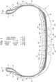
- Fig. 1 is a view showing a tire-width direction cross section of a tire 1, which is a pneumatic tire according to the present embodiment.
- the tire 1 is a tire for a passenger vehicle, for example.
- the specific structure of the tire 1 is left/right symmetrical in a cross section in the tire-width direction.
- reference symbol S1 is a tire equatorial plane.
- the tire equatorial plane S1 is a plane intersecting a tire rotational axis (tire meridian axis), and is positioned at the center in the tire-width direction.
- the cross-sectional view of Fig. 1 is a tire-width direction cross-sectional view (tire meridian axis cross-sectional view) of an unloaded state in which the tire 1 is mounted to a standard rim and filled with standard internal pressure.
- standard rim indicates a rim serving as a standard decided by JATMA corresponding to the tire size.
- standard internal pressure is 180 kPa in the case of the tire being for a passenger vehicle, for example.
- tire-width direction is a direction parallel to the tire rotational axis, and is the left/right direction in the paper plane in the cross-sectional view of Fig. 1 .
- Fig. 1 it is illustrated as the tire-width direction X.
- the tire-width direction inner side is a direction near the tire equatorial plane S1, and is the central side in the paper plane of Fig. 1 .
- Tire-width direction outer side is a direction distanced from the tire equatorial plane S1, and is the left side and right side in the paper plane of Fig. 1 .
- tire-radial direction is a direction perpendicular to the tire rotational axis, and is the vertical direction in Fig. 1 .
- a tire-radial direction outer side is a direction distanced from the tire rotational axis, and is a lower side in the paper plane of Fig. 1 .
- Tire-radial direction inner side is a direction approaching the tire rotational axis, and is an upper side in the paper plane of Fig. 1 .
- the tire 1 includes: a pair of beads 10 provided at both sides in the tire-width direction; a pair of sidewalls 20 extending from each of the pair of beads 10 to the outer side in the tire-radial direction; tread 30 arranged between the pair of sidewalls 20; a carcass ply 40 arranged between the pair of beads 10; and an inner liner 50 arranged on the tire inner cavity side of the carcass ply 40.
- the bead 10 includes a bead core 11, bead filler 12 extending in the tire-radial direction outer side of the bead core 11, a chafer 13, and rim strip rubber 14.
- the bead core 11 is an annular member formed by winding a bead wire made of metal covered with rubber around several times, and is a member playing the role of fixing the tire 1 filled with air to the rim.
- the bead filler 12 is a rubber member which takes on a tapered shape as extending to the outer side in the tire radial direction.
- the bead filler 12 is a member provided to raise the rigidity of a circumferential portion of the bead 10, and ensure high maneuverability and stability.
- the bead filler 12, for example, is configured from rubber having higher hardness than the surrounding rubber members.
- the chafer 13 is provided to the inner side in the tire-radial direction of the carcass ply 40 provided around the bead core 11.
- the rim strip rubber 14 is arranged on the outer side in the tire-width direction of the chafer 13 and carcass ply 40.
- the rim strip rubber 14 is a member which contacts the rim to which the tire 1 is mounted.
- the sidewall 20 includes sidewall rubber 21 arranged on the outer side in the tire-width direction of the carcass ply 40.
- the sidewall rubber 21 configures an outer wall surface of the tire 1.
- the sidewall rubber 21 is a portion which bends the most upon the tire 1 exhibiting a cushioning action, and usually flexible rubber having fatigue resistance is adopted therein.
- the tread 30 includes an endless belt 31 and cap ply 32, and tread rubber 33.
- the belt 31 is arranged at an outer side in the tire-radial direction of the carcass ply 40.
- the cap ply 32 is arranged at an outer side in the tire-radial direction of the belt 31.
- the belt 31 is a member reinforcing the tread 30.
- the belt 31 in the present embodiment is a two-layer structure including a belt 311 on the inner side and a belt 312 on the outer side.
- the belt 311 on the inner side and the belt 312 on the outer side both have a structure in which a plurality of cords such as steel cords is covered with rubber. It should be noted that the belt 31 is not limited to a two-layer structure, and may have a structure of one layer or three or more layers.
- the cap ply 32 is a member reinforcing the tread 30 together with the belt 31.
- the cap ply 32 for example, has a structure in which a plurality of organic fiber cords having an insulation property such as polyimide fibers is covered with rubber.
- the tread rubber 33 is arranged on the outer side in the tire-radial direction of the cap ply 32.
- the tread rubber 33 is a member constituting the tire tread (contact surface with road surface) 331 during normal travel.
- the tread pattern 34 has a plurality of main grooves 341 aligned in the tire-width direction. Each of the plurality of main grooves 341 extends along the tire circumferential direction.
- the carcass ply 40 configures a ply serving as the backbone of the tire 1.
- the carcass ply 40 is embedded within the tire 1, in a form passing through the pair of sidewalls 20 and the tread 30 between the pair of beads 10.
- the carcass ply 40 includes a plurality of carcass cords serving as the backbone of the tire 1.
- the plurality of carcass cords extends in the tire-width direction, for example, and are arranged side by side in the tire-circumferential direction.
- This carcass cord is configured from an insulative organic fiber cord such as polyester or polyamide, or the like.
- the plurality of carcass cords is coated by rubber, whereby the carcass ply 40 is configured.
- the carcass ply 40 includes a ply main body part 401 which extends from one bead core 11 to the other bead core 11, and extends between the tread 30 and bead 10; a pair of elbow-shaped bends 402 which fold back from the ply main body part 401 at the bead core 11; and a pair of folding parts 403 which extend from each of the elbow-shaped bends 402 to an outer side in the tire-radial direction.
- the ply main body part 401, the elbow-shaped bend 402 and folding part 403 are continuous.
- the ply main body part 401 is arranged at the inner side in the tire-width direction of the bead core 11 and bead filler 12 on the inner side in the tire-radial direction
- the folding part 403 is arranged at the outer side in the tire-width direction of the bead core 11 and bead filler 12 at the inner side in the tire-radial direction. In a portion other than the bead core 11 and bead filler 12, the folding part 403 is overlapped with the ply main body part 401.
- the elbow-shaped bend 402 configures a portion most to the inner side in the tire-radial direction of the carcass ply 40.
- the carcass ply 40 of the present embodiment is a one-layer structure; however, the carcass ply 40 is not limited to a one-layer structure, and may have a two-layer or three or more layer-structure.
- the aforementioned chafer 13 of the bead 10 is provided so as to surround the end on the inner side in the tire-radial direction of the carcass ply 40 including the elbow-shaped bend 402.
- the rim strip rubber 14 is arranged at the outer side in the tire-width direction of the chafer 13 and the folding part 403 of the carcass ply 40.
- the end on the outer side in the tire-radial direction of the rim strip rubber 14 is covered by the aforementioned sidewall rubber 21.
- the inner liner 50 covers the tire inner surface between the pair of beads.
- the inner liner 50 covers the inner surface of the ply main body part 401 of the carcass ply 40 and the inner surface of the chafer 13 of the pair of beads 10.
- the inner liner 50 is configured by air permeation resistant rubber, whereby the air inside the tire inner cavity is prevented from leaking to outside.
- the tire 1 according to the present embodiment further includes the sealant layer 60 and sound absorbing layer 70.
- the sealant layer 60 is arranged at the inner surface 501 on the tire inner cavity side corresponding to at least the tread 30 of the inner liner 50.
- the width of the sealant layer 60 i.e. length dimension in the tire-width direction, is set to about 1.1 times the width of the tire tread 331 of the tread 30 serving as the contact width of the tire 1, for example.
- the sealant layer 60 may be arranged so as to overhang from the tread 30 to the outer side in the tire-width direction, and include part on the side of the tread 30 of the sidewall 20.
- the sealant layer 60 is pasted to the inner liner 50 by the stickiness inherent thereto.
- the thickness of the sealant layer 60 is on the order of 1 mm or greater and 10 mm or less, for example.
- the sound absorbing layer 70 is arranged at the inner surface 601 on the tire inner cavity side of the sealant layer 60. The sound absorbing layer 70 is pasted to the sealant layer 60 by way of the stickiness of the sealant layer 60.
- Fig. 2 is a development view showing the inner surface of the tire 1, and schematically shows the sealant layer 60 and sound absorbing layer 70 provided to the inner surface of the tire 1.
- Fig. 2 shows the tire-width direction by the arrow X, and shows the tire-circumferential direction by the arrow Z.
- the sealant layer 60 is formed from one belt-like sealant material 61 pasted while circling along the tire-circumferential direction to the inner surface 501 of the inner liner 50.
- the sealant layer 60 has a plurality of annular circling parts 62 and a plurality of transition parts 63 formed by the sealant material 61.
- the reference symbol 61A indicates the pasting starting end of the sealant material 61
- reference symbol 61B indicates the pasting finishing end of the sealant material 61.
- the sealant material 61 is continuously pasted from one end side in the tire-width direction to the other end side (left side to right side in Fig. 2 ), while circling to configure as shown by the arrow in the middle drawing, from the pasting starting end 61A until the pasting finishing end 61B.
- the circling part 62 is formed by the sealant material 61 being pasted on the inner surface 501 of the inner liner 50 in parallel to the tire-circumferential direction.
- a plurality of circling parts 62 are arranged in parallel so as to be adjacent in a state in close proximity with each other in the tire-width direction.
- the plurality of transition parts 63 slope with a predetermined angle relative to the tire-circumferential direction, and are arranged in parallel so as to be adjacent in a state in close proximity with each other.
- the transition part 63 is provided to a part in the tire-circumferential direction of the circling part 62.
- the transition part 63 is a portion at which the sealant material 61 transitions to one side in the tire-width direction (right side in Fig. 2 ), after one circling part 62 is formed by the sealant material 61 being pasted approximately once around the inner surface 501 of the inner liner 50.
- the transition part 63 is a portion provided to part of the circling part 62, and connects adjacent circling parts 62 in the tire-width direction to form an angle relative to the tire-circumferential direction.
- the next circling part 62 is pasted adjacent on one side in the tire-width direction of the already pasted circling part 62 through the transition part 63.
- the next circling part 62 adjacent on one side in the tire-width direction through the transition part 63 is repeatedly formed, whereby the sealant layer 60 is provided.
- the plurality of transition parts 63 are respectively arranged at approximately the same position in the tire-circumferential direction, and arranged in parallel in the tire-width direction.
- step pasting upon pasting the sealant material 61 to the tire inner surface, the pasting method of sequentially pasting in the tire-width direction the circling parts 62 parallel in the tire-circumferential direction while passing through the transition parts 63 may be referred to as step pasting below.
- the sealant material 61 for example, it is possible to use a sealing member having stickiness made by blending a plasticizer such as polyisobutylene and polybutene, a tackifier such as a thermoplastic olefin/diolefin copolymer, and a filler such as carbon black and silica, into unvulcanized or semi-vulcanized butyl rubber, for example. It should be noted that, not limiting thereto, the sealant material 61 may be another known sealing member that is being used conventionally.
- step paste the sealant material 61 it is possible to perform by discharging and coating the sealant material 61 onto the inner surface 501 of the inner liner 50, which is the inner surface of the tire 1, from the nozzle 100, while rotating the tire 1 around its axis, and moving the nozzle 100 in the tire-width direction, as shown in Fig. 3 .
- the nozzle 100 is attached to the leading end of an extruder (not shown), and is inserted to the inner side of the tire 1.
- the sealant material 61 extruded from this extruder is discharged and coated on the inner surface of the tire 1 from the leading end of the nozzle 100.
- the width-direction cross section of the tire 1 is shown, and the tire-width direction X, tire-radial direction Y and tire-circumferential direction Z are each shown.
- the reference symbol G is the axis of rotation of the tire 1.
- One circling part 62 is coated by rotating the tire 1 approximately one time in a state stopping movement in the tire-width direction, while discharging the sealant material 61 continuously from the nozzle 100, and while continuously rotating the tire 1 around its axis.
- the transition part 63 is coated meanwhile.
- the movement in the tire-width direction is stopped, and the circling part 62 next to the previously coated circling part 62 is coated.
- sealant layer 60 is formed by the sealant material 61 in this way, and the sound absorbing layer 70 is subsequently arranged on the tire inner cavity side of the sealant layer 60.
- the initial circling part 62A on one end side in the tire-width direction (left side in Fig. 2 ) formed first among the plurality of circling part 62 has a first circling overlap part 62A1 which overlaps in the tire-thickness direction at the transition part 63 to the next circling part 62 from the initial circling part 62A, as shown in Fig. 2 .
- the finishing circling part 62B on the other end side in the tire-width direction (right side in Fig.
- the second circling overlap part 62B1 is a portion at which the pasting finish end 61B overlaps over the transition part 63.
- the sound absorbing layer 70 is formed with a sound absorbing material 71 consisting of sponge or the like formed with foaming material.
- the sound absorbing material 71 is an interconnecting foam body including several pores, and having permeability with outside air.
- a material for example, flexible urethane foam can be exemplified.
- the sound absorbing layer 70 is pasted by at least one sheet of sound absorbing material 71 being wound in a ring shape on the inner surface 601 of the sealant layer 60. As shown in Fig. 2 , the sound absorbing material 71 has a joint 71A at which circulation-direction ends opposing each other are joined. It should be noted that the sound absorbing layer 70 may be configured by at least two sound absorbing materials 71 being arranged in a state linked in a ring shape.
- the sound absorbing material 71 As characteristics of the sound absorbing material 71, from the viewpoint of weight balance of the pneumatic tire, it preferably has density no greater than 60 kg/m 3 , and more preferably has density no greater than 40 kg/m 3 . In addition, the sound absorbing material 71, from the viewpoint of durability, preferably has a tensile strength of at least 30 kPA, and a tear strength of at least 2.0 N/cm (JIS K6400-5).
- the dimension 70W in the tire-width direction of the sound absorbing layer 70 is preferably at least 90% to 100% relative to the dimension 60W in the tire-width direction of the sealant layer 60. Then, the sound absorbing layer 70 is preferably arranged so as to fit within the tire-width direction of the sealant layer 60. Furthermore, each of both tire-width direction ends 702 of the sound absorbing layer 70 is preferably located more to the inner side in the tire-radial direction than the first circling overlap part 62A1 and second circling overlap part 62B1 of the sealant layer 60, and not overlapping each other.
- the position of the joint 71A of the sound absorbing layer 70 and the position of the first circling overlap part 62A1 and second circling overlap part 62B1 of the sealant layer 60 is shifted in the tire-circumferential direction and not to overlap each other.
- this hole is automatically plugged by the sealant layer 60, and the puncture is prevented before it happens.
- the road noise during travel is absorbed by the sound absorbing layer 70 and decreases.
- Fig. 4 shows an example of coating the sealant material 61 in a spiral shape.
- the region in which adjacent sealant material 61 wound in a spiral shape overlap (shown by the hatched area in the drawing) exist long in the circumferential direction, in the initial circling part 82A along the tire-circumferential direction on the left end in the tire-width direction in the drawing, and the final circling part 82B along the tire-circumferential direction on the right end.
- the overlap area of the sealant material 61 is large in this way, defects arise such that the variation in thickness of the sealant layer becomes greater, and leads to a decline in adhesiveness of the sound absorbing layer to the sealant layer.
- the dimension in the tire-width direction of the sound absorbing layer 70 is at least 90% to 100% relative to the dimension in the tire-width direction of the sealant layer 60, and the sound absorbing layer 70 is arranged so as to fit within the tire-width direction of the sealant layer 60.
- the initial circling part 62A on one end side in the tire-width direction and a final circling part 62B on another end side in the tire-width direction among the plurality of circling parts 62 of the sealant layer 60 have a first circling overlap part 62A1 and second circling overlap 62B1 which overlap in the tire-thickness direction at the transition part 63;
- the sound absorbing layer 70 is formed by sound absorbing material 71 wound along the tire-circumferential direction on the inner surface 601 of the sealant layer 60 and having the joint part 71A at which circumferential-direction ends opposing each other join; and positions in the tire-circumferential of the joint part 71A of the sound absorbing layer 70 and the first circling overlap part 62A1 and second circling overlap part 62B1 of the sealant layer 60 differ.
- the joint part 71A of the sound absorbing layer 70, and first circling overlap part 62A1 and second circling overlap part 62B1 of the sealant layer 60 thereby do not overlap, the joint part 71A of the sound absorbing layer 70 will hardly peel from the sealant layer 60, and adhesiveness of the sound absorbing layer 70 to the sealant layer 60 is maintained.
- the initial circling part 62A on one end side in the tire-width direction and the final circling part 62B on another end side in the tire-width direction among the plurality of circling parts 62 of the sealant layer 60 have the first circling overlap part 62A1 and second circling overlap part 62B1 which overlap in the tire-thickness direction at the transition part 63; and each of both tire-width direction ends 702 of the sound absorbing layer 70 is located more to the inner side in the tire-width direction than the first circling overlap part 62A1 and second circling overlap part 62B1 of the sealant layer 60.
- both tire-width direction ends 702 of the sound absorbing layer 70 thereby do not overlap the first circling overlap part 62A1 and second circling overlap part 62B1 of the sealant layer 60, both tire-width direction ends 702 of the sound absorbing layer 70 will hardly peel from the sealant layer 60, and adhesiveness of the sound absorbing layer 70 to the sealant layer 60 is maintained.
- the method for producing the pneumatic tires according to the present embodiment includes: forming the sealant layer on the inner surface 501 of the inner liner 50, which is an inner surface of the tire 1, followed by arranging the sound absorbing layer 70 on the tire inner cavity side of the sealant layer 60, the method including forming the sealant layer 60, while continuously rotating the tire 1 around its axis upon forming the sealant layer 60, by repeating an operation of discharging a sealant material 61 from a nozzle 100 disposed at the tire 1 inner cavity side onto an inner surface of the tire 1 to form annular circling parts 62 parallel to a tire-circumferential direction from the sealant material 61, then relatively moving the nozzle 100 in the tire-width direction relative to the tire 1, while discharging the sealant material 61 from the nozzle 100, followed by discharging the sealant material 61 from the nozzle 100 onto the inner surface of the tire 1, thereby forming from the sealant material 61, on one side in the tire-width direction of said circling part
- the overlap area of the sealant material 61 in the sealant layer 60 drastically decreases compared to the conventional case of winding in a spiral shape, variation in thickness is suppressed, and unevenness decreases, whereby an improvement in adhesion of the sound absorbing layer 70 to the sealant layer 60 is achieved.
- the present invention is not limited to the above embodiment, and even if carrying out modifications, improvements and the like in a scope that can achieve the object of the present invention, are included in the scope of the present invention.
- the plurality of circling parts 62 of the sealant layer 60 are formed by circling around once the sealant material 61 and pasting; however, it may be configured to obtain a predetermined thickness with the circling number as a few times.
- it may be a mode in which the sound absorbing material 71 forming the sound absorbing layer 70 joins a plurality of pieces divided in the tire-radial direction.
- the tire 1 may be moved in the tire-width direction, or both the tire 1 and nozzle 131 maybe moved in the tire-width direction, instead of moving the nozzle 100 in the tire-width direction.
Landscapes
- Engineering & Computer Science (AREA)
- Mechanical Engineering (AREA)
- Tires In General (AREA)
- Tyre Moulding (AREA)
Abstract
Description
- The present invention relates to a pneumatic tire for vehicles and a method for producing this.
- Conventionally, a pneumatic tire has been known which includes a puncture prevention function whereby a hole in the tire formed during puncture is automatically plugged by a sealant layer provided to the inner surface of the tire. For example,
Patent Document 1 discloses a pneumatic tire in which a sealant layer is formed by a substantially cord-like sealant material arranged by continuously coating in a spiral shape along the tire inner surface, and a sound absorbing layer is provided to the inner side of the sealant layer. - Patent Document 1:
Japanese Patent No.6184523 - When coating the sealant material in a spiral shape, an area in which sealant material overlaps exists long in the circumferential direction, at both ends in the tire-width direction, which is an initial circling portion and a final circling portion. If the overlap area of the sealant material is large, defects will arise such as variation in the thickness of the sealant layer increasing, and leading to a decline in the adhesiveness of the sound absorbing layer to the sealant layer.
- The present invention has been made taking account of the above situation, and has an object of providing a pneumatic tire and a method for producing the same whereby an overlap area of a sealant material decreases, variation in thickness of the sealant layer is suppressed, and an improvement in adhesiveness of a sound absorbing layer to the sealant layer is achieved.
- A pneumatic tire according to the present invention includes: a pair of beads; a pair of sidewalls extending from each of the pair of beads to an outer side in a tire-radial direction; a tread disposed between the pair of sidewalls; a carcass ply bridged between the pair of beads; an inner liner disposed at a tire inner cavity side of the carcass ply; a sealant layer disposed at an inner surface of the tire inner cavity side corresponding to at least the tread of the inner liner; and a sound absorbing layer disposed at a tire inner cavity side of the sealant layer, in which the sealant layer is formed from a belt-like sealant material pasted while circling the inner surface of the inner liner, the sealant layer includes: a plurality of annular circling parts parallel to a tire-circumferential direction in which the sealant material is disposed in parallel in a state adjacent in the tire-width direction, and a plurality of transition parts provided to a part in the tire-circumferential direction of the circling part, and at which the sealant material transitions to the circling part adjacent at one side in the tire-width direction.
- A method for producing the pneumatic tire according to the present invention forms a sealant layer on an inner surface of a tire, and then disposes a sound absorbing layer on a tire inner cavity side of the sealant layer, the method including forming a sealant layer, while continuously rotating the tire around its axis upon forming the sealant layer, by repeating an operation of discharging a sealant material from a nozzle disposed at the tire inner cavity side onto an inner surface of the tire to form annular circling parts parallel to a tire-circumferential direction from the sealant material, then relatively moving the nozzle in the tire-width direction relative to the tire, while discharging the sealant material from the nozzle, followed by discharging the sealant material from the nozzle onto the inner surface of the tire, thereby forming from the sealant material, on one side in the tire-width direction of said circling part, a next circling part adjacent to said circling part to form on an inner surface of the tire a sealant layer in which a plurality of the circling parts are arranged in parallel in the tire-width direction.
- According to the present invention, it is possible to provide a pneumatic tire and a method for producing the same whereby an overlap area of a sealant material decreases, variation in thickness of the sealant layer is suppressed, and an improvement in adhesiveness of a sound absorbing layer to the sealant layer is achieved.
-
-
Fig. 1 is a cross-sectional view in a tire-width direction of the tire according to an embodiment of the present invention; -
Fig. 2 is a development view showing an inner surface of the tire according to the embodiment of the present invention, and schematically showing a sealant layer and sound absorbing layer; -
Fig. 3 is a view schematically showing a state of coating a sealant material on a tire inner surface by a nozzle, upon producing the tire according to the embodiment of the present invention; and -
Fig. 4 is a development view of a tire inner surface schematically showing a conventional example of pasting a sealant material in a spiral shape onto the tire inner surface. - Hereinafter, an embodiment will be explained while referencing the drawings.
Fig. 1 is a view showing a tire-width direction cross section of atire 1, which is a pneumatic tire according to the present embodiment. Thetire 1 is a tire for a passenger vehicle, for example. The specific structure of thetire 1 is left/right symmetrical in a cross section in the tire-width direction. In the drawings, reference symbol S1 is a tire equatorial plane. The tire equatorial plane S1 is a plane intersecting a tire rotational axis (tire meridian axis), and is positioned at the center in the tire-width direction. - It should be noted that the cross-sectional view of
Fig. 1 is a tire-width direction cross-sectional view (tire meridian axis cross-sectional view) of an unloaded state in which thetire 1 is mounted to a standard rim and filled with standard internal pressure. It should be noted that standard rim indicates a rim serving as a standard decided by JATMA corresponding to the tire size. In addition, standard internal pressure is 180 kPa in the case of the tire being for a passenger vehicle, for example. - Herein, tire-width direction is a direction parallel to the tire rotational axis, and is the left/right direction in the paper plane in the cross-sectional view of
Fig. 1 . InFig. 1 , it is illustrated as the tire-width direction X. Then, the tire-width direction inner side is a direction near the tire equatorial plane S1, and is the central side in the paper plane ofFig. 1 . Tire-width direction outer side is a direction distanced from the tire equatorial plane S1, and is the left side and right side in the paper plane ofFig. 1 . In addition, tire-radial direction is a direction perpendicular to the tire rotational axis, and is the vertical direction inFig. 1 . InFig. 1 , it is illustrated as the tire-radial direction Y. Then, a tire-radial direction outer side is a direction distanced from the tire rotational axis, and is a lower side in the paper plane ofFig. 1 . Tire-radial direction inner side is a direction approaching the tire rotational axis, and is an upper side in the paper plane ofFig. 1 . - As shown in
Fig. 1 , thetire 1 includes: a pair ofbeads 10 provided at both sides in the tire-width direction; a pair ofsidewalls 20 extending from each of the pair ofbeads 10 to the outer side in the tire-radial direction;tread 30 arranged between the pair ofsidewalls 20; acarcass ply 40 arranged between the pair ofbeads 10; and aninner liner 50 arranged on the tire inner cavity side of thecarcass ply 40. - The
bead 10 includes abead core 11,bead filler 12 extending in the tire-radial direction outer side of thebead core 11, achafer 13, andrim strip rubber 14. - The
bead core 11 is an annular member formed by winding a bead wire made of metal covered with rubber around several times, and is a member playing the role of fixing thetire 1 filled with air to the rim. Thebead filler 12 is a rubber member which takes on a tapered shape as extending to the outer side in the tire radial direction. Thebead filler 12 is a member provided to raise the rigidity of a circumferential portion of thebead 10, and ensure high maneuverability and stability. Thebead filler 12, for example, is configured from rubber having higher hardness than the surrounding rubber members. - The
chafer 13 is provided to the inner side in the tire-radial direction of thecarcass ply 40 provided around thebead core 11. Therim strip rubber 14 is arranged on the outer side in the tire-width direction of thechafer 13 andcarcass ply 40. Therim strip rubber 14 is a member which contacts the rim to which thetire 1 is mounted. - The
sidewall 20 includessidewall rubber 21 arranged on the outer side in the tire-width direction of thecarcass ply 40. Thesidewall rubber 21 configures an outer wall surface of thetire 1. Thesidewall rubber 21 is a portion which bends the most upon thetire 1 exhibiting a cushioning action, and usually flexible rubber having fatigue resistance is adopted therein. - The
tread 30 includes anendless belt 31 andcap ply 32, andtread rubber 33. - The
belt 31 is arranged at an outer side in the tire-radial direction of thecarcass ply 40. Thecap ply 32 is arranged at an outer side in the tire-radial direction of thebelt 31. Thebelt 31 is a member reinforcing thetread 30. Thebelt 31 in the present embodiment is a two-layer structure including abelt 311 on the inner side and abelt 312 on the outer side. Thebelt 311 on the inner side and thebelt 312 on the outer side both have a structure in which a plurality of cords such as steel cords is covered with rubber. It should be noted that thebelt 31 is not limited to a two-layer structure, and may have a structure of one layer or three or more layers. - The
cap ply 32 is a member reinforcing thetread 30 together with thebelt 31. Thecap ply 32, for example, has a structure in which a plurality of organic fiber cords having an insulation property such as polyimide fibers is covered with rubber. By providing thecap ply 32, it is possible to achieve an improvement in durability and a reduction in road noise during travel. - The
tread rubber 33 is arranged on the outer side in the tire-radial direction of thecap ply 32. Thetread rubber 33 is a member constituting the tire tread (contact surface with road surface) 331 during normal travel. Atread pattern 34 configured by a plurality of grooves, for example, is provided in thetire tread 331 of thetread rubber 33. Thetread pattern 34 has a plurality ofmain grooves 341 aligned in the tire-width direction. Each of the plurality ofmain grooves 341 extends along the tire circumferential direction. - The carcass ply 40 configures a ply serving as the backbone of the
tire 1. The carcass ply 40 is embedded within thetire 1, in a form passing through the pair ofsidewalls 20 and thetread 30 between the pair ofbeads 10. The carcass ply 40 includes a plurality of carcass cords serving as the backbone of thetire 1. The plurality of carcass cords extends in the tire-width direction, for example, and are arranged side by side in the tire-circumferential direction. This carcass cord is configured from an insulative organic fiber cord such as polyester or polyamide, or the like. The plurality of carcass cords is coated by rubber, whereby the carcass ply 40 is configured. - The carcass ply 40 includes a ply
main body part 401 which extends from onebead core 11 to theother bead core 11, and extends between thetread 30 andbead 10; a pair of elbow-shapedbends 402 which fold back from the plymain body part 401 at thebead core 11; and a pair offolding parts 403 which extend from each of the elbow-shapedbends 402 to an outer side in the tire-radial direction. The plymain body part 401, the elbow-shapedbend 402 andfolding part 403 are continuous. - The ply
main body part 401 is arranged at the inner side in the tire-width direction of thebead core 11 andbead filler 12 on the inner side in the tire-radial direction Thefolding part 403 is arranged at the outer side in the tire-width direction of thebead core 11 andbead filler 12 at the inner side in the tire-radial direction. In a portion other than thebead core 11 andbead filler 12, thefolding part 403 is overlapped with the plymain body part 401. The elbow-shapedbend 402 configures a portion most to the inner side in the tire-radial direction of thecarcass ply 40. - The carcass ply 40 of the present embodiment is a one-layer structure; however, the carcass ply 40 is not limited to a one-layer structure, and may have a two-layer or three or more layer-structure.
- The
aforementioned chafer 13 of thebead 10 is provided so as to surround the end on the inner side in the tire-radial direction of the carcass ply 40 including the elbow-shapedbend 402. In addition, therim strip rubber 14 is arranged at the outer side in the tire-width direction of thechafer 13 and thefolding part 403 of thecarcass ply 40. The end on the outer side in the tire-radial direction of therim strip rubber 14 is covered by theaforementioned sidewall rubber 21. - The
inner liner 50 covers the tire inner surface between the pair of beads. Theinner liner 50 covers the inner surface of the plymain body part 401 of thecarcass ply 40 and the inner surface of thechafer 13 of the pair ofbeads 10. Theinner liner 50 is configured by air permeation resistant rubber, whereby the air inside the tire inner cavity is prevented from leaking to outside. - As shown in
Fig. 1 , thetire 1 according to the present embodiment further includes thesealant layer 60 andsound absorbing layer 70. - The
sealant layer 60 is arranged at theinner surface 501 on the tire inner cavity side corresponding to at least thetread 30 of theinner liner 50. The width of thesealant layer 60, i.e. length dimension in the tire-width direction, is set to about 1.1 times the width of thetire tread 331 of thetread 30 serving as the contact width of thetire 1, for example. Thesealant layer 60 may be arranged so as to overhang from thetread 30 to the outer side in the tire-width direction, and include part on the side of thetread 30 of thesidewall 20. Thesealant layer 60 is pasted to theinner liner 50 by the stickiness inherent thereto. The thickness of thesealant layer 60 is on the order of 1 mm or greater and 10 mm or less, for example. Thesound absorbing layer 70 is arranged at theinner surface 601 on the tire inner cavity side of thesealant layer 60. Thesound absorbing layer 70 is pasted to thesealant layer 60 by way of the stickiness of thesealant layer 60. -
Fig. 2 is a development view showing the inner surface of thetire 1, and schematically shows thesealant layer 60 andsound absorbing layer 70 provided to the inner surface of thetire 1.Fig. 2 shows the tire-width direction by the arrow X, and shows the tire-circumferential direction by the arrow Z. - As shown in
Fig. 2 , thesealant layer 60 is formed from one belt-like sealant material 61 pasted while circling along the tire-circumferential direction to theinner surface 501 of theinner liner 50. Thesealant layer 60 has a plurality of annular circlingparts 62 and a plurality oftransition parts 63 formed by thesealant material 61. - In
Fig. 2 , thereference symbol 61A indicates the pasting starting end of thesealant material 61, andreference symbol 61B indicates the pasting finishing end of thesealant material 61. As shown inFig. 2 , thesealant material 61 is continuously pasted from one end side in the tire-width direction to the other end side (left side to right side inFig. 2 ), while circling to configure as shown by the arrow in the middle drawing, from thepasting starting end 61A until thepasting finishing end 61B. - The circling
part 62 is formed by thesealant material 61 being pasted on theinner surface 501 of theinner liner 50 in parallel to the tire-circumferential direction. A plurality of circlingparts 62 are arranged in parallel so as to be adjacent in a state in close proximity with each other in the tire-width direction. The plurality oftransition parts 63 slope with a predetermined angle relative to the tire-circumferential direction, and are arranged in parallel so as to be adjacent in a state in close proximity with each other. - The
transition part 63 is provided to a part in the tire-circumferential direction of the circlingpart 62. Thetransition part 63 is a portion at which thesealant material 61 transitions to one side in the tire-width direction (right side inFig. 2 ), after one circlingpart 62 is formed by thesealant material 61 being pasted approximately once around theinner surface 501 of theinner liner 50. In other words, thetransition part 63 is a portion provided to part of the circlingpart 62, and connects adjacent circlingparts 62 in the tire-width direction to form an angle relative to the tire-circumferential direction. The next circlingpart 62 is pasted adjacent on one side in the tire-width direction of the already pasted circlingpart 62 through thetransition part 63. The next circlingpart 62 adjacent on one side in the tire-width direction through thetransition part 63 is repeatedly formed, whereby thesealant layer 60 is provided. In the present embodiment, the plurality oftransition parts 63 are respectively arranged at approximately the same position in the tire-circumferential direction, and arranged in parallel in the tire-width direction. - In this way, upon pasting the
sealant material 61 to the tire inner surface, the pasting method of sequentially pasting in the tire-width direction the circlingparts 62 parallel in the tire-circumferential direction while passing through thetransition parts 63 may be referred to as step pasting below. - As the
sealant material 61, for example, it is possible to use a sealing member having stickiness made by blending a plasticizer such as polyisobutylene and polybutene, a tackifier such as a thermoplastic olefin/diolefin copolymer, and a filler such as carbon black and silica, into unvulcanized or semi-vulcanized butyl rubber, for example. It should be noted that, not limiting thereto, thesealant material 61 may be another known sealing member that is being used conventionally. - Next, the method of producing the tire according to the present embodiment including step pasting the
sealant material 61 will be explained. To step paste thesealant material 61, it is possible to perform by discharging and coating thesealant material 61 onto theinner surface 501 of theinner liner 50, which is the inner surface of thetire 1, from thenozzle 100, while rotating thetire 1 around its axis, and moving thenozzle 100 in the tire-width direction, as shown inFig. 3 . Thenozzle 100 is attached to the leading end of an extruder (not shown), and is inserted to the inner side of thetire 1. Thesealant material 61 extruded from this extruder is discharged and coated on the inner surface of thetire 1 from the leading end of thenozzle 100. InFig. 3 , the width-direction cross section of thetire 1 is shown, and the tire-width direction X, tire-radial direction Y and tire-circumferential direction Z are each shown. InFig. 3 , the reference symbol G is the axis of rotation of thetire 1. - One circling
part 62 is coated by rotating thetire 1 approximately one time in a state stopping movement in the tire-width direction, while discharging thesealant material 61 continuously from thenozzle 100, and while continuously rotating thetire 1 around its axis. Next, when moving thenozzle 100 to one side in the tire-width direction by the width of thesealant material 61, thetransition part 63 is coated meanwhile. Next, the movement in the tire-width direction is stopped, and the circlingpart 62 next to the previously coated circlingpart 62 is coated. By repeating the above operation, it is possible to step paste thesealant material 61 onto the formation area of thesealant layer 60. When coating and pasting thesealant material 61 to the entirety of the formation area of thesealant layer 60, discharge ofsealant material 61 from thenozzle 100 stops. Thesealant layer 60 is formed by thesealant material 61 in this way, and thesound absorbing layer 70 is subsequently arranged on the tire inner cavity side of thesealant layer 60. - In the case of the
sealant material 61 being step pasted to theinner surface 501 of theinner liner 50 in the above way, the initial circlingpart 62A on one end side in the tire-width direction (left side inFig. 2 ) formed first among the plurality of circlingpart 62 has a first circling overlap part 62A1 which overlaps in the tire-thickness direction at thetransition part 63 to the next circlingpart 62 from the initial circlingpart 62A, as shown inFig. 2 . In addition, thefinishing circling part 62B on the other end side in the tire-width direction (right side inFig. 2 ) formed last has a circling overlap part 62B1 which overlaps in the tire-thickness direction with thetransition part 63 transitioning to thefinishing circling part 62B. The first circling overlap part 62A1 is a portion at which thetransition part 63 overlaps over the pasting startend 61A. The second circling overlap part 62B1 is a portion at which thepasting finish end 61B overlaps over thetransition part 63. - The
sound absorbing layer 70 is formed with asound absorbing material 71 consisting of sponge or the like formed with foaming material. Thesound absorbing material 71 is an interconnecting foam body including several pores, and having permeability with outside air. As such a material, for example, flexible urethane foam can be exemplified. - The
sound absorbing layer 70 is pasted by at least one sheet ofsound absorbing material 71 being wound in a ring shape on theinner surface 601 of thesealant layer 60. As shown inFig. 2 , thesound absorbing material 71 has a joint 71A at which circulation-direction ends opposing each other are joined. It should be noted that thesound absorbing layer 70 may be configured by at least twosound absorbing materials 71 being arranged in a state linked in a ring shape. - As characteristics of the
sound absorbing material 71, from the viewpoint of weight balance of the pneumatic tire, it preferably has density no greater than 60 kg/m3, and more preferably has density no greater than 40 kg/m3. In addition, thesound absorbing material 71, from the viewpoint of durability, preferably has a tensile strength of at least 30 kPA, and a tear strength of at least 2.0 N/cm (JIS K6400-5). - The
dimension 70W in the tire-width direction of thesound absorbing layer 70 is preferably at least 90% to 100% relative to thedimension 60W in the tire-width direction of thesealant layer 60. Then, thesound absorbing layer 70 is preferably arranged so as to fit within the tire-width direction of thesealant layer 60. Furthermore, each of both tire-width direction ends 702 of thesound absorbing layer 70 is preferably located more to the inner side in the tire-radial direction than the first circling overlap part 62A1 and second circling overlap part 62B1 of thesealant layer 60, and not overlapping each other. - In addition, it is preferable for the position of the joint 71A of the
sound absorbing layer 70 and the position of the first circling overlap part 62A1 and second circling overlap part 62B1 of thesealant layer 60 to be shifted in the tire-circumferential direction and not to overlap each other. - According to the
tire 1 of the aforementioned embodiment, in the case of a nail or the like poking thetread 30, for example, and a hole that reaches thesealant layer 60 occurring, this hole is automatically plugged by thesealant layer 60, and the puncture is prevented before it happens. In addition, the road noise during travel is absorbed by thesound absorbing layer 70 and decreases. - According to the
tire 1 of the present embodiment explained above, the following effects are exerted. - (1) The
tire 1 according to the present embodiment includes: a pair ofbeads 10; a pair ofsidewalls 20 extending from each of the pair ofbeads 10 to an outer side in the tire-radial direction; atread 30 arranged between the pair ofsidewalls 20; acarcass ply 40 bridged between the pair ofbeads 10; aninner liner 50 arranged on the tire inner cavity side of thecarcass ply 40; asealant layer 60 arranged on theinner surface 501 on the tire inner cavity side corresponding to at least thetread 30 of theinner liner 50; and asound absorbing layer 70 arranged on the tire inner cavity side of thesealant layer 60, in which thesealant layer 60 is formed from a belt-like sealant material 61 pasted while circling theinner surface 501 of theinner liner 50, and thesealant layer 60 has a plurality of annular circlingparts 62 parallel to the tire-circumferential direction in which thesealant material 61 are arranged in parallel in a state adjacent in the tire-width direction, and a plurality oftransition parts 63 provided to a part in the tire-circumferential direction of the circlingpart 62, and in which thesealant material 61 transitions to an adjacent circlingpart 62 on one side in the tire-width direction. - Since the overlap area of the
sealant material 61 drastically decreases compared to a conventional case of winding in a spiral shape, in thesealant layer 60, variation is thickness is suppressed, and unevenness decreases, whereby an improvement in adhesion of thesound absorbing layer 70 to thesealant layer 60 is achieved. -
Fig. 4 shows an example of coating thesealant material 61 in a spiral shape. According to this, the region in whichadjacent sealant material 61 wound in a spiral shape overlap (shown by the hatched area in the drawing) exist long in the circumferential direction, in the initial circlingpart 82A along the tire-circumferential direction on the left end in the tire-width direction in the drawing, and the final circlingpart 82B along the tire-circumferential direction on the right end. If the overlap area of thesealant material 61 is large in this way, defects arise such that the variation in thickness of the sealant layer becomes greater, and leads to a decline in adhesiveness of the sound absorbing layer to the sealant layer. In contrast, by performing step pasting which aligns in the tire-width direction the circlingparts 62 parallel to the tire-circumferential direction, without circling thesealant material 61 in a spiral shape in the present embodiment, it is possible to drastically decrease the overlap area of thesealant material 61 in the aforementioned way. - (2) In the
tire 1 according to the present embodiment, the dimension in the tire-width direction of thesound absorbing layer 70 is at least 90% to 100% relative to the dimension in the tire-width direction of thesealant layer 60, and thesound absorbing layer 70 is arranged so as to fit within the tire-width direction of thesealant layer 60. - It is thereby possible to reduce the surface area of a portion not covered by the
sound absorbing layer 70 of thesealant layer 60, and possible to suppress clinging of debris to thesealant layer 60 having stickiness. In addition, since the tire-width direction end of thesound absorbing layer 70 clings to thesealant layer 60, thesound absorbing layer 70 hardly peels from thesealant layer 60, and the sound absorbing performance is maintained. - (3) In the
tire 1 according to the present embodiment, the initial circlingpart 62A on one end side in the tire-width direction and a final circlingpart 62B on another end side in the tire-width direction among the plurality of circlingparts 62 of thesealant layer 60 have a first circling overlap part 62A1 and second circling overlap 62B1 which overlap in the tire-thickness direction at thetransition part 63; thesound absorbing layer 70 is formed bysound absorbing material 71 wound along the tire-circumferential direction on theinner surface 601 of thesealant layer 60 and having thejoint part 71A at which circumferential-direction ends opposing each other join; and positions in the tire-circumferential of thejoint part 71A of thesound absorbing layer 70 and the first circling overlap part 62A1 and second circling overlap part 62B1 of thesealant layer 60 differ. - Since the
joint part 71A of thesound absorbing layer 70, and first circling overlap part 62A1 and second circling overlap part 62B1 of thesealant layer 60 thereby do not overlap, thejoint part 71A of thesound absorbing layer 70 will hardly peel from thesealant layer 60, and adhesiveness of thesound absorbing layer 70 to thesealant layer 60 is maintained. - (4) In the
tire 1 according to the present embodiment, the initial circlingpart 62A on one end side in the tire-width direction and the final circlingpart 62B on another end side in the tire-width direction among the plurality of circlingparts 62 of thesealant layer 60 have the first circling overlap part 62A1 and second circling overlap part 62B1 which overlap in the tire-thickness direction at thetransition part 63; and each of both tire-width direction ends 702 of thesound absorbing layer 70 is located more to the inner side in the tire-width direction than the first circling overlap part 62A1 and second circling overlap part 62B1 of thesealant layer 60. - Since both tire-width direction ends 702 of the
sound absorbing layer 70 thereby do not overlap the first circling overlap part 62A1 and second circling overlap part 62B1 of thesealant layer 60, both tire-width direction ends 702 of thesound absorbing layer 70 will hardly peel from thesealant layer 60, and adhesiveness of thesound absorbing layer 70 to thesealant layer 60 is maintained. - (5) The method for producing the pneumatic tires according to the present embodiment includes: forming the sealant layer on the inner surface 501 of the inner liner 50, which is an inner surface of the tire 1, followed by arranging the sound absorbing layer 70 on the tire inner cavity side of the sealant layer 60, the method including forming the sealant layer 60, while continuously rotating the tire 1 around its axis upon forming the sealant layer 60, by repeating an operation of discharging a sealant material 61 from a nozzle 100 disposed at the tire 1 inner cavity side onto an inner surface of the tire 1 to form annular circling parts 62 parallel to a tire-circumferential direction from the sealant material 61, then relatively moving the nozzle 100 in the tire-width direction relative to the tire 1, while discharging the sealant material 61 from the nozzle 100, followed by discharging the sealant material 61 from the nozzle 100 onto the inner surface of the tire 1, thereby forming from the sealant material 61, on one side in the tire-width direction of said circling part 62, a next circling part 62 adjacent to said circling part 62 to form on an inner surface of the tire 1 a sealant layer 60 in which a plurality of the circling parts 62 are arranged in parallel in the tire-width direction.
- Since the overlap area of the
sealant material 61 in thesealant layer 60 drastically decreases compared to the conventional case of winding in a spiral shape, variation in thickness is suppressed, and unevenness decreases, whereby an improvement in adhesion of thesound absorbing layer 70 to thesealant layer 60 is achieved. - Although a specific embodiment of the present invention has been explained above, the present invention is not limited to the above embodiment, and even if carrying out modifications, improvements and the like in a scope that can achieve the object of the present invention, are included in the scope of the present invention. For example, the plurality of circling
parts 62 of thesealant layer 60 are formed by circling around once thesealant material 61 and pasting; however, it may be configured to obtain a predetermined thickness with the circling number as a few times. In addition, it may be a mode in which thesound absorbing material 71 forming thesound absorbing layer 70 joins a plurality of pieces divided in the tire-radial direction. In the case of step pasting thesealant material 61 to form a plurality of circlingparts 62, thetire 1 may be moved in the tire-width direction, or both thetire 1 and nozzle 131 maybe moved in the tire-width direction, instead of moving thenozzle 100 in the tire-width direction. -
- 1 tire (pneumatic tire)
- 10 bead
- 20 sidewall
- 30 tread
- 40 carcass ply
- 50 inner liner
- 60 sealant layer
- 61 sealant material
- 62 circling part
- 62A initial circling part
- 62A1 first circling overlap part
- 62B final circling part
- 62B1 second circling overlap part
- 63 transition part
- 70 sound absorbing layer
- 71A joint
Claims (6)
- A pneumatic tire comprising:a pair of beads;a pair of sidewalls extending from each of the pair of beads to an outer side in a tire-radial direction;a tread disposed between the pair of sidewalls;a carcass ply bridged between the pair of beads;an inner liner disposed at a tire inner cavity side of the carcass ply;a sealant layer disposed at an inner surface of the tire inner cavity side corresponding to at least the tread of the inner liner; anda sound absorbing layer disposed at a tire inner cavity side of the sealant layer,wherein the sealant layer is formed from a belt-like sealant material pasted while circling the inner surface of the inner liner,wherein the sealant layer includes: a plurality of annular circling parts parallel to a tire-circumferential direction in which the sealant material is disposed in parallel in a state adjacent in the tire-width direction, anda plurality of transition parts provided to a part in the tire-circumferential direction of the circling part, and at which the sealant material transitions to the circling part adjacent at one side in the tire-width direction.
- The pneumatic tire according to claim 1, wherein a dimension in the tire-width direction of the sound absorbing layer is at least 90% to 100% relative to a dimension in the tire-width direction of the sealant layer, and the sound absorbing layer is disposed so as to fit within the tire-width direction of the sealant layer.
- The pneumatic tire according to claim 1 or 2, wherein an initial circling part on one end side in the tire-width direction and a final circling part on another end side in the tire-width direction among the plurality of circling parts respectively have a circling overlap part which overlap in the tire-thickness direction at the transition part,wherein the sound absorbing layer is formed from a sound absorbing material wound along the tire-circumferential direction on the inner surface of the sealant layer and having a joint part at which circumferential-direction ends opposing each other join, andwherein positions of the joint part and the circling overlap part differ in the tire-circumferential direction.
- The pneumatic tire according to any one of claims 1 to 3, wherein an initial circling part on one end side in the tire-width direction and a final circling part on another end side in the tire-width direction among the plurality of circling parts respectively have a circling overlap part which overlap in the tire-thickness direction at the transition part, and
wherein both tire-width direction ends of the sound absorbing layer are located more to an inner side in the tire-width direction than the circling overlap part. - The pneumatic tire according to any one of claims 1 to 4, wherein a plurality of the transition parts are respectively disposed at substantially the same position in the tire-circumferential direction, and disposed in parallel in the tire-width direction.
- A method for producing a pneumatic tire which forms a sealant layer on an inner surface of a tire, and then disposes a sound absorbing layer on a tire inner cavity side of the sealant layer, the method comprising: forming a sealant layer,while continuously rotating the tire around its axis upon forming the sealant layer,by repeating an operation of discharging a sealant material from a nozzle disposed at the tire inner cavity side onto an inner surface of the tire to form annular circling parts parallel to a tire-circumferential direction from the sealant material, then relatively moving the nozzle in the tire-width direction relative to the tire, while discharging the sealant material from the nozzle, followed by discharging the sealant material from the nozzle onto the inner surface of the tire, thereby forming from the sealant material, on one side in the tire-width direction of said circling part, a next circling part adjacent to said circling part to form on an inner surface of the tire a sealant layer in which a plurality of the circling parts are arranged in parallel in the tire-width direction.
Applications Claiming Priority (2)
| Application Number | Priority Date | Filing Date | Title |
|---|---|---|---|
| JP2020203253A JP7607445B2 (en) | 2020-12-08 | 2020-12-08 | Pneumatic tire and method of manufacturing same |
| PCT/JP2021/041856 WO2022124012A1 (en) | 2020-12-08 | 2021-11-15 | Pneumatic tire and method for producing same |
Publications (3)
| Publication Number | Publication Date |
|---|---|
| EP4261052A1 true EP4261052A1 (en) | 2023-10-18 |
| EP4261052A4 EP4261052A4 (en) | 2024-06-05 |
| EP4261052B1 EP4261052B1 (en) | 2025-08-27 |
Family
ID=81974360
Family Applications (1)
| Application Number | Title | Priority Date | Filing Date |
|---|---|---|---|
| EP21903116.8A Active EP4261052B1 (en) | 2020-12-08 | 2021-11-15 | Pneumatic tire and method for producing same |
Country Status (3)
| Country | Link |
|---|---|
| EP (1) | EP4261052B1 (en) |
| JP (1) | JP7607445B2 (en) |
| WO (1) | WO2022124012A1 (en) |
Families Citing this family (2)
| Publication number | Priority date | Publication date | Assignee | Title |
|---|---|---|---|---|
| JP2024071928A (en) * | 2022-11-15 | 2024-05-27 | Toyo Tire株式会社 | Manufacturing method of pneumatic tire |
| JP2024071926A (en) * | 2022-11-15 | 2024-05-27 | Toyo Tire株式会社 | Pneumatic tire and method of manufacturing same |
Family Cites Families (6)
| Publication number | Priority date | Publication date | Assignee | Title |
|---|---|---|---|---|
| US4398583A (en) * | 1981-11-23 | 1983-08-16 | The Goodyear Tire & Rubber Company | Tire and method of applying sealant |
| JP5001798B2 (en) * | 2007-11-19 | 2012-08-15 | 東洋ゴム工業株式会社 | Tire and tire molding method |
| JP4862918B2 (en) | 2009-06-05 | 2012-01-25 | 横浜ゴム株式会社 | Pneumatic tire |
| US11267297B2 (en) * | 2014-01-30 | 2022-03-08 | Sumitomo Rubber Industries, Ltd. | Sealant tire |
| JP6235990B2 (en) * | 2014-10-17 | 2017-11-22 | 住友ゴム工業株式会社 | Sealant tire |
| US20200189215A1 (en) | 2018-12-13 | 2020-06-18 | The Goodyear Tire & Rubber Company | Method for forming a sealant layer in a tire |
-
2020
- 2020-12-08 JP JP2020203253A patent/JP7607445B2/en active Active
-
2021
- 2021-11-15 WO PCT/JP2021/041856 patent/WO2022124012A1/en not_active Ceased
- 2021-11-15 EP EP21903116.8A patent/EP4261052B1/en active Active
Also Published As
| Publication number | Publication date |
|---|---|
| EP4261052B1 (en) | 2025-08-27 |
| JP2022090756A (en) | 2022-06-20 |
| WO2022124012A1 (en) | 2022-06-16 |
| EP4261052A4 (en) | 2024-06-05 |
| JP7607445B2 (en) | 2024-12-27 |
Similar Documents
| Publication | Publication Date | Title |
|---|---|---|
| JP2006062518A (en) | Heavy duty pneumatic tire and manufacturing method thereof | |
| US20130126064A1 (en) | Method for producing pneumatic tire and pneumatic tire | |
| JP2020093546A (en) | Method for forming sealant layer in tire | |
| EP4261052B1 (en) | Pneumatic tire and method for producing same | |
| JP4625319B2 (en) | Pneumatic tire and manufacturing method thereof | |
| CN103889699B (en) | For the manufacture of airtyred method | |
| WO2006028083A1 (en) | Run flat tire and method of manufacturing run flat tire | |
| JP2009090974A (en) | Pneumatic tire | |
| EP4261025B1 (en) | Pneumatic tire and method for manufacturing same | |
| JP2023087224A (en) | pneumatic tire | |
| JP4757699B2 (en) | Pneumatic tire manufacturing method and pneumatic tire | |
| JP7612401B2 (en) | Pneumatic tire and method of manufacturing same | |
| JP5452123B2 (en) | Pneumatic tire manufacturing method | |
| JP4469201B2 (en) | Pneumatic tire manufacturing method and pneumatic tire | |
| EP4371751B1 (en) | Production method of a pneumatic tire with a sealant layer | |
| JP2023087225A (en) | pneumatic tire | |
| JP2024092594A (en) | Pneumatic tires | |
| EP4371752A1 (en) | Production method of a pneumatic tire with a selant layer and tire obtained thereby | |
| JP2011148392A (en) | Tire tube | |
| EP0723884A2 (en) | A pneumatic tire and an unvulcanized carcass as an intermediate article in its manufacture | |
| CN121986029A (en) | Pneumatic tires and their manufacturing methods | |
| JP2000247119A (en) | Pneumatic tire and method of manufacturing the same | |
| AU702582B2 (en) | A pneumatic tire and an unvulcanized carcass as an intermediate article in its manufacture | |
| JP2025089726A (en) | Pneumatic tires | |
| CN121866167A (en) | Pneumatic tires and their manufacturing methods |
Legal Events
| Date | Code | Title | Description |
|---|---|---|---|
| STAA | Information on the status of an ep patent application or granted ep patent |
Free format text: STATUS: THE INTERNATIONAL PUBLICATION HAS BEEN MADE |
|
| PUAI | Public reference made under article 153(3) epc to a published international application that has entered the european phase |
Free format text: ORIGINAL CODE: 0009012 |
|
| STAA | Information on the status of an ep patent application or granted ep patent |
Free format text: STATUS: REQUEST FOR EXAMINATION WAS MADE |
|
| 17P | Request for examination filed |
Effective date: 20230601 |
|
| AK | Designated contracting states |
Kind code of ref document: A1 Designated state(s): AL AT BE BG CH CY CZ DE DK EE ES FI FR GB GR HR HU IE IS IT LI LT LU LV MC MK MT NL NO PL PT RO RS SE SI SK SM TR |
|
| DAV | Request for validation of the european patent (deleted) | ||
| DAX | Request for extension of the european patent (deleted) | ||
| A4 | Supplementary search report drawn up and despatched |
Effective date: 20240507 |
|
| RIC1 | Information provided on ipc code assigned before grant |
Ipc: B60C 5/00 20060101ALI20240430BHEP Ipc: B29D 30/06 20060101ALI20240430BHEP Ipc: B60C 19/12 20060101AFI20240430BHEP |
|
| STAA | Information on the status of an ep patent application or granted ep patent |
Free format text: STATUS: EXAMINATION IS IN PROGRESS |
|
| 17Q | First examination report despatched |
Effective date: 20241119 |
|
| GRAP | Despatch of communication of intention to grant a patent |
Free format text: ORIGINAL CODE: EPIDOSNIGR1 |
|
| STAA | Information on the status of an ep patent application or granted ep patent |
Free format text: STATUS: GRANT OF PATENT IS INTENDED |
|
| INTG | Intention to grant announced |
Effective date: 20250428 |
|
| GRAS | Grant fee paid |
Free format text: ORIGINAL CODE: EPIDOSNIGR3 |
|
| GRAA | (expected) grant |
Free format text: ORIGINAL CODE: 0009210 |
|
| STAA | Information on the status of an ep patent application or granted ep patent |
Free format text: STATUS: THE PATENT HAS BEEN GRANTED |
|
| P01 | Opt-out of the competence of the unified patent court (upc) registered |
Free format text: CASE NUMBER: APP_31422/2025 Effective date: 20250630 |
|
| AK | Designated contracting states |
Kind code of ref document: B1 Designated state(s): AL AT BE BG CH CY CZ DE DK EE ES FI FR GB GR HR HU IE IS IT LI LT LU LV MC MK MT NL NO PL PT RO RS SE SI SK SM TR |
|
| REG | Reference to a national code |
Ref country code: CH Ref legal event code: EP |
|
| REG | Reference to a national code |
Ref country code: DE Ref legal event code: R096 Ref document number: 602021037452 Country of ref document: DE |
|
| REG | Reference to a national code |
Ref country code: IE Ref legal event code: FG4D |
|
| REG | Reference to a national code |
Ref country code: NL Ref legal event code: MP Effective date: 20250827 |
|
| PG25 | Lapsed in a contracting state [announced via postgrant information from national office to epo] |
Ref country code: IS Free format text: LAPSE BECAUSE OF FAILURE TO SUBMIT A TRANSLATION OF THE DESCRIPTION OR TO PAY THE FEE WITHIN THE PRESCRIBED TIME-LIMIT Effective date: 20251227 |
|
| PGFP | Annual fee paid to national office [announced via postgrant information from national office to epo] |
Ref country code: DE Payment date: 20251126 Year of fee payment: 5 |
|
| PG25 | Lapsed in a contracting state [announced via postgrant information from national office to epo] |
Ref country code: NO Free format text: LAPSE BECAUSE OF FAILURE TO SUBMIT A TRANSLATION OF THE DESCRIPTION OR TO PAY THE FEE WITHIN THE PRESCRIBED TIME-LIMIT Effective date: 20251127 |
|
| REG | Reference to a national code |
Ref country code: LT Ref legal event code: MG9D |
|
| PG25 | Lapsed in a contracting state [announced via postgrant information from national office to epo] |
Ref country code: PT Free format text: LAPSE BECAUSE OF FAILURE TO SUBMIT A TRANSLATION OF THE DESCRIPTION OR TO PAY THE FEE WITHIN THE PRESCRIBED TIME-LIMIT Effective date: 20251229 |
|
| PG25 | Lapsed in a contracting state [announced via postgrant information from national office to epo] |
Ref country code: FI Free format text: LAPSE BECAUSE OF FAILURE TO SUBMIT A TRANSLATION OF THE DESCRIPTION OR TO PAY THE FEE WITHIN THE PRESCRIBED TIME-LIMIT Effective date: 20250827 |
|
| PG25 | Lapsed in a contracting state [announced via postgrant information from national office to epo] |
Ref country code: NL Free format text: LAPSE BECAUSE OF FAILURE TO SUBMIT A TRANSLATION OF THE DESCRIPTION OR TO PAY THE FEE WITHIN THE PRESCRIBED TIME-LIMIT Effective date: 20250827 Ref country code: HR Free format text: LAPSE BECAUSE OF FAILURE TO SUBMIT A TRANSLATION OF THE DESCRIPTION OR TO PAY THE FEE WITHIN THE PRESCRIBED TIME-LIMIT Effective date: 20250827 |
|
| PG25 | Lapsed in a contracting state [announced via postgrant information from national office to epo] |
Ref country code: GR Free format text: LAPSE BECAUSE OF FAILURE TO SUBMIT A TRANSLATION OF THE DESCRIPTION OR TO PAY THE FEE WITHIN THE PRESCRIBED TIME-LIMIT Effective date: 20251128 |
|
| PG25 | Lapsed in a contracting state [announced via postgrant information from national office to epo] |
Ref country code: SE Free format text: LAPSE BECAUSE OF FAILURE TO SUBMIT A TRANSLATION OF THE DESCRIPTION OR TO PAY THE FEE WITHIN THE PRESCRIBED TIME-LIMIT Effective date: 20250827 |
|
| PG25 | Lapsed in a contracting state [announced via postgrant information from national office to epo] |
Ref country code: LV Free format text: LAPSE BECAUSE OF FAILURE TO SUBMIT A TRANSLATION OF THE DESCRIPTION OR TO PAY THE FEE WITHIN THE PRESCRIBED TIME-LIMIT Effective date: 20250827 |
|
| PG25 | Lapsed in a contracting state [announced via postgrant information from national office to epo] |
Ref country code: PL Free format text: LAPSE BECAUSE OF FAILURE TO SUBMIT A TRANSLATION OF THE DESCRIPTION OR TO PAY THE FEE WITHIN THE PRESCRIBED TIME-LIMIT Effective date: 20250827 Ref country code: BG Free format text: LAPSE BECAUSE OF FAILURE TO SUBMIT A TRANSLATION OF THE DESCRIPTION OR TO PAY THE FEE WITHIN THE PRESCRIBED TIME-LIMIT Effective date: 20250827 |
|
| PG25 | Lapsed in a contracting state [announced via postgrant information from national office to epo] |
Ref country code: RS Free format text: LAPSE BECAUSE OF FAILURE TO SUBMIT A TRANSLATION OF THE DESCRIPTION OR TO PAY THE FEE WITHIN THE PRESCRIBED TIME-LIMIT Effective date: 20251127 |
|
| PG25 | Lapsed in a contracting state [announced via postgrant information from national office to epo] |
Ref country code: ES Free format text: LAPSE BECAUSE OF FAILURE TO SUBMIT A TRANSLATION OF THE DESCRIPTION OR TO PAY THE FEE WITHIN THE PRESCRIBED TIME-LIMIT Effective date: 20250827 |
|
| REG | Reference to a national code |
Ref country code: AT Ref legal event code: MK05 Ref document number: 1829607 Country of ref document: AT Kind code of ref document: T Effective date: 20250827 |
|
| PG25 | Lapsed in a contracting state [announced via postgrant information from national office to epo] |
Ref country code: RO Free format text: LAPSE BECAUSE OF FAILURE TO SUBMIT A TRANSLATION OF THE DESCRIPTION OR TO PAY THE FEE WITHIN THE PRESCRIBED TIME-LIMIT Effective date: 20250827 |
|
| PG25 | Lapsed in a contracting state [announced via postgrant information from national office to epo] |
Ref country code: SM Free format text: LAPSE BECAUSE OF FAILURE TO SUBMIT A TRANSLATION OF THE DESCRIPTION OR TO PAY THE FEE WITHIN THE PRESCRIBED TIME-LIMIT Effective date: 20250827 |
|
| PG25 | Lapsed in a contracting state [announced via postgrant information from national office to epo] |
Ref country code: DK Free format text: LAPSE BECAUSE OF FAILURE TO SUBMIT A TRANSLATION OF THE DESCRIPTION OR TO PAY THE FEE WITHIN THE PRESCRIBED TIME-LIMIT Effective date: 20250827 |
|
| PG25 | Lapsed in a contracting state [announced via postgrant information from national office to epo] |
Ref country code: AT Free format text: LAPSE BECAUSE OF FAILURE TO SUBMIT A TRANSLATION OF THE DESCRIPTION OR TO PAY THE FEE WITHIN THE PRESCRIBED TIME-LIMIT Effective date: 20250827 |
|
| PG25 | Lapsed in a contracting state [announced via postgrant information from national office to epo] |
Ref country code: IT Free format text: LAPSE BECAUSE OF FAILURE TO SUBMIT A TRANSLATION OF THE DESCRIPTION OR TO PAY THE FEE WITHIN THE PRESCRIBED TIME-LIMIT Effective date: 20250827 |
|
| PG25 | Lapsed in a contracting state [announced via postgrant information from national office to epo] |
Ref country code: CZ Free format text: LAPSE BECAUSE OF FAILURE TO SUBMIT A TRANSLATION OF THE DESCRIPTION OR TO PAY THE FEE WITHIN THE PRESCRIBED TIME-LIMIT Effective date: 20250827 |
|
| PG25 | Lapsed in a contracting state [announced via postgrant information from national office to epo] |
Ref country code: EE Free format text: LAPSE BECAUSE OF FAILURE TO SUBMIT A TRANSLATION OF THE DESCRIPTION OR TO PAY THE FEE WITHIN THE PRESCRIBED TIME-LIMIT Effective date: 20250827 Ref country code: SK Free format text: LAPSE BECAUSE OF FAILURE TO SUBMIT A TRANSLATION OF THE DESCRIPTION OR TO PAY THE FEE WITHIN THE PRESCRIBED TIME-LIMIT Effective date: 20250827 |