EP4261020A1 - Composite material fusion method - Google Patents
Composite material fusion method Download PDFInfo
- Publication number
- EP4261020A1 EP4261020A1 EP23152433.1A EP23152433A EP4261020A1 EP 4261020 A1 EP4261020 A1 EP 4261020A1 EP 23152433 A EP23152433 A EP 23152433A EP 4261020 A1 EP4261020 A1 EP 4261020A1
- Authority
- EP
- European Patent Office
- Prior art keywords
- composite material
- fusion
- resin film
- resin
- machine processed
- Prior art date
- Legal status (The legal status is an assumption and is not a legal conclusion. Google has not performed a legal analysis and makes no representation as to the accuracy of the status listed.)
- Pending
Links
Images


Classifications
-
- B—PERFORMING OPERATIONS; TRANSPORTING
- B29—WORKING OF PLASTICS; WORKING OF SUBSTANCES IN A PLASTIC STATE IN GENERAL
- B29C—SHAPING OR JOINING OF PLASTICS; SHAPING OF MATERIAL IN A PLASTIC STATE, NOT OTHERWISE PROVIDED FOR; AFTER-TREATMENT OF THE SHAPED PRODUCTS, e.g. REPAIRING
- B29C65/00—Joining or sealing of preformed parts, e.g. welding of plastics materials; Apparatus therefor
- B29C65/48—Joining or sealing of preformed parts, e.g. welding of plastics materials; Apparatus therefor using adhesives, i.e. using supplementary joining material; solvent bonding
- B29C65/4805—Joining or sealing of preformed parts, e.g. welding of plastics materials; Apparatus therefor using adhesives, i.e. using supplementary joining material; solvent bonding characterised by the type of adhesives
- B29C65/481—Non-reactive adhesives, e.g. physically hardening adhesives
- B29C65/4815—Hot melt adhesives, e.g. thermoplastic adhesives
-
- B—PERFORMING OPERATIONS; TRANSPORTING
- B32—LAYERED PRODUCTS
- B32B—LAYERED PRODUCTS, i.e. PRODUCTS BUILT-UP OF STRATA OF FLAT OR NON-FLAT, e.g. CELLULAR OR HONEYCOMB, FORM
- B32B27/00—Layered products comprising a layer of synthetic resin
- B32B27/06—Layered products comprising a layer of synthetic resin as the main or only constituent of a layer, which is next to another layer of the same or of a different material
-
- B—PERFORMING OPERATIONS; TRANSPORTING
- B29—WORKING OF PLASTICS; WORKING OF SUBSTANCES IN A PLASTIC STATE IN GENERAL
- B29C—SHAPING OR JOINING OF PLASTICS; SHAPING OF MATERIAL IN A PLASTIC STATE, NOT OTHERWISE PROVIDED FOR; AFTER-TREATMENT OF THE SHAPED PRODUCTS, e.g. REPAIRING
- B29C65/00—Joining or sealing of preformed parts, e.g. welding of plastics materials; Apparatus therefor
- B29C65/02—Joining or sealing of preformed parts, e.g. welding of plastics materials; Apparatus therefor by heating, with or without pressure
- B29C65/18—Joining or sealing of preformed parts, e.g. welding of plastics materials; Apparatus therefor by heating, with or without pressure using heated tools
-
- B—PERFORMING OPERATIONS; TRANSPORTING
- B29—WORKING OF PLASTICS; WORKING OF SUBSTANCES IN A PLASTIC STATE IN GENERAL
- B29C—SHAPING OR JOINING OF PLASTICS; SHAPING OF MATERIAL IN A PLASTIC STATE, NOT OTHERWISE PROVIDED FOR; AFTER-TREATMENT OF THE SHAPED PRODUCTS, e.g. REPAIRING
- B29C65/00—Joining or sealing of preformed parts, e.g. welding of plastics materials; Apparatus therefor
- B29C65/48—Joining or sealing of preformed parts, e.g. welding of plastics materials; Apparatus therefor using adhesives, i.e. using supplementary joining material; solvent bonding
- B29C65/50—Joining or sealing of preformed parts, e.g. welding of plastics materials; Apparatus therefor using adhesives, i.e. using supplementary joining material; solvent bonding using adhesive tape, e.g. thermoplastic tape; using threads or the like
- B29C65/5057—Joining or sealing of preformed parts, e.g. welding of plastics materials; Apparatus therefor using adhesives, i.e. using supplementary joining material; solvent bonding using adhesive tape, e.g. thermoplastic tape; using threads or the like positioned between the surfaces to be joined
-
- B—PERFORMING OPERATIONS; TRANSPORTING
- B29—WORKING OF PLASTICS; WORKING OF SUBSTANCES IN A PLASTIC STATE IN GENERAL
- B29C—SHAPING OR JOINING OF PLASTICS; SHAPING OF MATERIAL IN A PLASTIC STATE, NOT OTHERWISE PROVIDED FOR; AFTER-TREATMENT OF THE SHAPED PRODUCTS, e.g. REPAIRING
- B29C66/00—General aspects of processes or apparatus for joining preformed parts
- B29C66/01—General aspects dealing with the joint area or with the area to be joined
- B29C66/02—Preparation of the material, in the area to be joined, prior to joining or welding
- B29C66/022—Mechanical pre-treatments, e.g. reshaping
-
- B—PERFORMING OPERATIONS; TRANSPORTING
- B29—WORKING OF PLASTICS; WORKING OF SUBSTANCES IN A PLASTIC STATE IN GENERAL
- B29C—SHAPING OR JOINING OF PLASTICS; SHAPING OF MATERIAL IN A PLASTIC STATE, NOT OTHERWISE PROVIDED FOR; AFTER-TREATMENT OF THE SHAPED PRODUCTS, e.g. REPAIRING
- B29C66/00—General aspects of processes or apparatus for joining preformed parts
- B29C66/01—General aspects dealing with the joint area or with the area to be joined
- B29C66/02—Preparation of the material, in the area to be joined, prior to joining or welding
- B29C66/022—Mechanical pre-treatments, e.g. reshaping
- B29C66/0224—Mechanical pre-treatments, e.g. reshaping with removal of material
- B29C66/02241—Cutting, e.g. by using waterjets, or sawing
-
- B—PERFORMING OPERATIONS; TRANSPORTING
- B29—WORKING OF PLASTICS; WORKING OF SUBSTANCES IN A PLASTIC STATE IN GENERAL
- B29C—SHAPING OR JOINING OF PLASTICS; SHAPING OF MATERIAL IN A PLASTIC STATE, NOT OTHERWISE PROVIDED FOR; AFTER-TREATMENT OF THE SHAPED PRODUCTS, e.g. REPAIRING
- B29C66/00—General aspects of processes or apparatus for joining preformed parts
- B29C66/01—General aspects dealing with the joint area or with the area to be joined
- B29C66/05—Particular design of joint configurations
- B29C66/10—Particular design of joint configurations particular design of the joint cross-sections
- B29C66/11—Joint cross-sections comprising a single joint-segment, i.e. one of the parts to be joined comprising a single joint-segment in the joint cross-section
- B29C66/112—Single lapped joints
- B29C66/1122—Single lap to lap joints, i.e. overlap joints
-
- B—PERFORMING OPERATIONS; TRANSPORTING
- B29—WORKING OF PLASTICS; WORKING OF SUBSTANCES IN A PLASTIC STATE IN GENERAL
- B29C—SHAPING OR JOINING OF PLASTICS; SHAPING OF MATERIAL IN A PLASTIC STATE, NOT OTHERWISE PROVIDED FOR; AFTER-TREATMENT OF THE SHAPED PRODUCTS, e.g. REPAIRING
- B29C66/00—General aspects of processes or apparatus for joining preformed parts
- B29C66/01—General aspects dealing with the joint area or with the area to be joined
- B29C66/05—Particular design of joint configurations
- B29C66/10—Particular design of joint configurations particular design of the joint cross-sections
- B29C66/11—Joint cross-sections comprising a single joint-segment, i.e. one of the parts to be joined comprising a single joint-segment in the joint cross-section
- B29C66/116—Single bevelled joints, i.e. one of the parts to be joined being bevelled in the joint area
- B29C66/1162—Single bevel to bevel joints, e.g. mitre joints
-
- B—PERFORMING OPERATIONS; TRANSPORTING
- B29—WORKING OF PLASTICS; WORKING OF SUBSTANCES IN A PLASTIC STATE IN GENERAL
- B29C—SHAPING OR JOINING OF PLASTICS; SHAPING OF MATERIAL IN A PLASTIC STATE, NOT OTHERWISE PROVIDED FOR; AFTER-TREATMENT OF THE SHAPED PRODUCTS, e.g. REPAIRING
- B29C66/00—General aspects of processes or apparatus for joining preformed parts
- B29C66/01—General aspects dealing with the joint area or with the area to be joined
- B29C66/05—Particular design of joint configurations
- B29C66/10—Particular design of joint configurations particular design of the joint cross-sections
- B29C66/12—Joint cross-sections combining only two joint-segments; Tongue and groove joints; Tenon and mortise joints; Stepped joint cross-sections
- B29C66/128—Stepped joint cross-sections
- B29C66/1284—Stepped joint cross-sections comprising at least one butt joint-segment
- B29C66/12841—Stepped joint cross-sections comprising at least one butt joint-segment comprising at least two butt joint-segments
-
- B—PERFORMING OPERATIONS; TRANSPORTING
- B29—WORKING OF PLASTICS; WORKING OF SUBSTANCES IN A PLASTIC STATE IN GENERAL
- B29C—SHAPING OR JOINING OF PLASTICS; SHAPING OF MATERIAL IN A PLASTIC STATE, NOT OTHERWISE PROVIDED FOR; AFTER-TREATMENT OF THE SHAPED PRODUCTS, e.g. REPAIRING
- B29C66/00—General aspects of processes or apparatus for joining preformed parts
- B29C66/01—General aspects dealing with the joint area or with the area to be joined
- B29C66/05—Particular design of joint configurations
- B29C66/10—Particular design of joint configurations particular design of the joint cross-sections
- B29C66/12—Joint cross-sections combining only two joint-segments; Tongue and groove joints; Tenon and mortise joints; Stepped joint cross-sections
- B29C66/128—Stepped joint cross-sections
- B29C66/1286—Stepped joint cross-sections comprising at least one bevelled joint-segment
-
- B—PERFORMING OPERATIONS; TRANSPORTING
- B29—WORKING OF PLASTICS; WORKING OF SUBSTANCES IN A PLASTIC STATE IN GENERAL
- B29C—SHAPING OR JOINING OF PLASTICS; SHAPING OF MATERIAL IN A PLASTIC STATE, NOT OTHERWISE PROVIDED FOR; AFTER-TREATMENT OF THE SHAPED PRODUCTS, e.g. REPAIRING
- B29C66/00—General aspects of processes or apparatus for joining preformed parts
- B29C66/01—General aspects dealing with the joint area or with the area to be joined
- B29C66/05—Particular design of joint configurations
- B29C66/10—Particular design of joint configurations particular design of the joint cross-sections
- B29C66/14—Particular design of joint configurations particular design of the joint cross-sections the joint having the same thickness as the thickness of the parts to be joined
-
- B—PERFORMING OPERATIONS; TRANSPORTING
- B29—WORKING OF PLASTICS; WORKING OF SUBSTANCES IN A PLASTIC STATE IN GENERAL
- B29C—SHAPING OR JOINING OF PLASTICS; SHAPING OF MATERIAL IN A PLASTIC STATE, NOT OTHERWISE PROVIDED FOR; AFTER-TREATMENT OF THE SHAPED PRODUCTS, e.g. REPAIRING
- B29C66/00—General aspects of processes or apparatus for joining preformed parts
- B29C66/01—General aspects dealing with the joint area or with the area to be joined
- B29C66/05—Particular design of joint configurations
- B29C66/301—Three-dimensional joints, i.e. the joined area being substantially non-flat
-
- B—PERFORMING OPERATIONS; TRANSPORTING
- B29—WORKING OF PLASTICS; WORKING OF SUBSTANCES IN A PLASTIC STATE IN GENERAL
- B29C—SHAPING OR JOINING OF PLASTICS; SHAPING OF MATERIAL IN A PLASTIC STATE, NOT OTHERWISE PROVIDED FOR; AFTER-TREATMENT OF THE SHAPED PRODUCTS, e.g. REPAIRING
- B29C66/00—General aspects of processes or apparatus for joining preformed parts
- B29C66/01—General aspects dealing with the joint area or with the area to be joined
- B29C66/349—Cooling the welding zone on the welding spot
- B29C66/3494—Cooling the welding zone on the welding spot while keeping the welding zone under pressure
-
- B—PERFORMING OPERATIONS; TRANSPORTING
- B29—WORKING OF PLASTICS; WORKING OF SUBSTANCES IN A PLASTIC STATE IN GENERAL
- B29C—SHAPING OR JOINING OF PLASTICS; SHAPING OF MATERIAL IN A PLASTIC STATE, NOT OTHERWISE PROVIDED FOR; AFTER-TREATMENT OF THE SHAPED PRODUCTS, e.g. REPAIRING
- B29C66/00—General aspects of processes or apparatus for joining preformed parts
- B29C66/40—General aspects of joining substantially flat articles, e.g. plates, sheets or web-like materials; Making flat seams in tubular or hollow articles; Joining single elements to substantially flat surfaces
- B29C66/41—Joining substantially flat articles ; Making flat seams in tubular or hollow articles
- B29C66/43—Joining a relatively small portion of the surface of said articles
-
- B—PERFORMING OPERATIONS; TRANSPORTING
- B29—WORKING OF PLASTICS; WORKING OF SUBSTANCES IN A PLASTIC STATE IN GENERAL
- B29C—SHAPING OR JOINING OF PLASTICS; SHAPING OF MATERIAL IN A PLASTIC STATE, NOT OTHERWISE PROVIDED FOR; AFTER-TREATMENT OF THE SHAPED PRODUCTS, e.g. REPAIRING
- B29C66/00—General aspects of processes or apparatus for joining preformed parts
- B29C66/50—General aspects of joining tubular articles; General aspects of joining long products, i.e. bars or profiled elements; General aspects of joining single elements to tubular articles, hollow articles or bars; General aspects of joining several hollow-preforms to form hollow or tubular articles
- B29C66/51—Joining tubular articles, profiled elements or bars; Joining single elements to tubular articles, hollow articles or bars; Joining several hollow-preforms to form hollow or tubular articles
- B29C66/52—Joining tubular articles, bars or profiled elements
- B29C66/524—Joining profiled elements
-
- B—PERFORMING OPERATIONS; TRANSPORTING
- B29—WORKING OF PLASTICS; WORKING OF SUBSTANCES IN A PLASTIC STATE IN GENERAL
- B29C—SHAPING OR JOINING OF PLASTICS; SHAPING OF MATERIAL IN A PLASTIC STATE, NOT OTHERWISE PROVIDED FOR; AFTER-TREATMENT OF THE SHAPED PRODUCTS, e.g. REPAIRING
- B29C66/00—General aspects of processes or apparatus for joining preformed parts
- B29C66/50—General aspects of joining tubular articles; General aspects of joining long products, i.e. bars or profiled elements; General aspects of joining single elements to tubular articles, hollow articles or bars; General aspects of joining several hollow-preforms to form hollow or tubular articles
- B29C66/51—Joining tubular articles, profiled elements or bars; Joining single elements to tubular articles, hollow articles or bars; Joining several hollow-preforms to form hollow or tubular articles
- B29C66/53—Joining single elements to tubular articles, hollow articles or bars
- B29C66/532—Joining single elements to the wall of tubular articles, hollow articles or bars
-
- B—PERFORMING OPERATIONS; TRANSPORTING
- B29—WORKING OF PLASTICS; WORKING OF SUBSTANCES IN A PLASTIC STATE IN GENERAL
- B29C—SHAPING OR JOINING OF PLASTICS; SHAPING OF MATERIAL IN A PLASTIC STATE, NOT OTHERWISE PROVIDED FOR; AFTER-TREATMENT OF THE SHAPED PRODUCTS, e.g. REPAIRING
- B29C66/00—General aspects of processes or apparatus for joining preformed parts
- B29C66/50—General aspects of joining tubular articles; General aspects of joining long products, i.e. bars or profiled elements; General aspects of joining single elements to tubular articles, hollow articles or bars; General aspects of joining several hollow-preforms to form hollow or tubular articles
- B29C66/51—Joining tubular articles, profiled elements or bars; Joining single elements to tubular articles, hollow articles or bars; Joining several hollow-preforms to form hollow or tubular articles
- B29C66/53—Joining single elements to tubular articles, hollow articles or bars
- B29C66/532—Joining single elements to the wall of tubular articles, hollow articles or bars
- B29C66/5326—Joining single elements to the wall of tubular articles, hollow articles or bars said single elements being substantially flat
-
- B—PERFORMING OPERATIONS; TRANSPORTING
- B29—WORKING OF PLASTICS; WORKING OF SUBSTANCES IN A PLASTIC STATE IN GENERAL
- B29C—SHAPING OR JOINING OF PLASTICS; SHAPING OF MATERIAL IN A PLASTIC STATE, NOT OTHERWISE PROVIDED FOR; AFTER-TREATMENT OF THE SHAPED PRODUCTS, e.g. REPAIRING
- B29C66/00—General aspects of processes or apparatus for joining preformed parts
- B29C66/50—General aspects of joining tubular articles; General aspects of joining long products, i.e. bars or profiled elements; General aspects of joining single elements to tubular articles, hollow articles or bars; General aspects of joining several hollow-preforms to form hollow or tubular articles
- B29C66/61—Joining from or joining on the inside
-
- B—PERFORMING OPERATIONS; TRANSPORTING
- B29—WORKING OF PLASTICS; WORKING OF SUBSTANCES IN A PLASTIC STATE IN GENERAL
- B29C—SHAPING OR JOINING OF PLASTICS; SHAPING OF MATERIAL IN A PLASTIC STATE, NOT OTHERWISE PROVIDED FOR; AFTER-TREATMENT OF THE SHAPED PRODUCTS, e.g. REPAIRING
- B29C66/00—General aspects of processes or apparatus for joining preformed parts
- B29C66/70—General aspects of processes or apparatus for joining preformed parts characterised by the composition, physical properties or the structure of the material of the parts to be joined; Joining with non-plastics material
- B29C66/71—General aspects of processes or apparatus for joining preformed parts characterised by the composition, physical properties or the structure of the material of the parts to be joined; Joining with non-plastics material characterised by the composition of the plastics material of the parts to be joined
-
- B—PERFORMING OPERATIONS; TRANSPORTING
- B29—WORKING OF PLASTICS; WORKING OF SUBSTANCES IN A PLASTIC STATE IN GENERAL
- B29C—SHAPING OR JOINING OF PLASTICS; SHAPING OF MATERIAL IN A PLASTIC STATE, NOT OTHERWISE PROVIDED FOR; AFTER-TREATMENT OF THE SHAPED PRODUCTS, e.g. REPAIRING
- B29C66/00—General aspects of processes or apparatus for joining preformed parts
- B29C66/70—General aspects of processes or apparatus for joining preformed parts characterised by the composition, physical properties or the structure of the material of the parts to be joined; Joining with non-plastics material
- B29C66/72—General aspects of processes or apparatus for joining preformed parts characterised by the composition, physical properties or the structure of the material of the parts to be joined; Joining with non-plastics material characterised by the structure of the material of the parts to be joined
- B29C66/721—Fibre-reinforced materials
- B29C66/7212—Fibre-reinforced materials characterised by the composition of the fibres
-
- B—PERFORMING OPERATIONS; TRANSPORTING
- B29—WORKING OF PLASTICS; WORKING OF SUBSTANCES IN A PLASTIC STATE IN GENERAL
- B29C—SHAPING OR JOINING OF PLASTICS; SHAPING OF MATERIAL IN A PLASTIC STATE, NOT OTHERWISE PROVIDED FOR; AFTER-TREATMENT OF THE SHAPED PRODUCTS, e.g. REPAIRING
- B29C66/00—General aspects of processes or apparatus for joining preformed parts
- B29C66/70—General aspects of processes or apparatus for joining preformed parts characterised by the composition, physical properties or the structure of the material of the parts to be joined; Joining with non-plastics material
- B29C66/73—General aspects of processes or apparatus for joining preformed parts characterised by the composition, physical properties or the structure of the material of the parts to be joined; Joining with non-plastics material characterised by the intensive physical properties of the material of the parts to be joined, by the optical properties of the material of the parts to be joined, by the extensive physical properties of the parts to be joined, by the state of the material of the parts to be joined or by the material of the parts to be joined being a thermoplastic or a thermoset
- B29C66/739—General aspects of processes or apparatus for joining preformed parts characterised by the composition, physical properties or the structure of the material of the parts to be joined; Joining with non-plastics material characterised by the intensive physical properties of the material of the parts to be joined, by the optical properties of the material of the parts to be joined, by the extensive physical properties of the parts to be joined, by the state of the material of the parts to be joined or by the material of the parts to be joined being a thermoplastic or a thermoset characterised by the material of the parts to be joined being a thermoplastic or a thermoset
- B29C66/7392—General aspects of processes or apparatus for joining preformed parts characterised by the composition, physical properties or the structure of the material of the parts to be joined; Joining with non-plastics material characterised by the intensive physical properties of the material of the parts to be joined, by the optical properties of the material of the parts to be joined, by the extensive physical properties of the parts to be joined, by the state of the material of the parts to be joined or by the material of the parts to be joined being a thermoplastic or a thermoset characterised by the material of the parts to be joined being a thermoplastic or a thermoset characterised by the material of at least one of the parts being a thermoplastic
- B29C66/73921—General aspects of processes or apparatus for joining preformed parts characterised by the composition, physical properties or the structure of the material of the parts to be joined; Joining with non-plastics material characterised by the intensive physical properties of the material of the parts to be joined, by the optical properties of the material of the parts to be joined, by the extensive physical properties of the parts to be joined, by the state of the material of the parts to be joined or by the material of the parts to be joined being a thermoplastic or a thermoset characterised by the material of the parts to be joined being a thermoplastic or a thermoset characterised by the material of at least one of the parts being a thermoplastic characterised by the materials of both parts being thermoplastics
-
- B—PERFORMING OPERATIONS; TRANSPORTING
- B32—LAYERED PRODUCTS
- B32B—LAYERED PRODUCTS, i.e. PRODUCTS BUILT-UP OF STRATA OF FLAT OR NON-FLAT, e.g. CELLULAR OR HONEYCOMB, FORM
- B32B37/00—Methods or apparatus for laminating, e.g. by curing or by ultrasonic bonding
- B32B37/06—Methods or apparatus for laminating, e.g. by curing or by ultrasonic bonding characterised by the heating method
-
- B—PERFORMING OPERATIONS; TRANSPORTING
- B32—LAYERED PRODUCTS
- B32B—LAYERED PRODUCTS, i.e. PRODUCTS BUILT-UP OF STRATA OF FLAT OR NON-FLAT, e.g. CELLULAR OR HONEYCOMB, FORM
- B32B37/00—Methods or apparatus for laminating, e.g. by curing or by ultrasonic bonding
- B32B37/10—Methods or apparatus for laminating, e.g. by curing or by ultrasonic bonding characterised by the pressing technique, e.g. using action of vacuum or fluid pressure
-
- B—PERFORMING OPERATIONS; TRANSPORTING
- B29—WORKING OF PLASTICS; WORKING OF SUBSTANCES IN A PLASTIC STATE IN GENERAL
- B29C—SHAPING OR JOINING OF PLASTICS; SHAPING OF MATERIAL IN A PLASTIC STATE, NOT OTHERWISE PROVIDED FOR; AFTER-TREATMENT OF THE SHAPED PRODUCTS, e.g. REPAIRING
- B29C65/00—Joining or sealing of preformed parts, e.g. welding of plastics materials; Apparatus therefor
- B29C65/48—Joining or sealing of preformed parts, e.g. welding of plastics materials; Apparatus therefor using adhesives, i.e. using supplementary joining material; solvent bonding
- B29C65/50—Joining or sealing of preformed parts, e.g. welding of plastics materials; Apparatus therefor using adhesives, i.e. using supplementary joining material; solvent bonding using adhesive tape, e.g. thermoplastic tape; using threads or the like
- B29C65/5007—Joining or sealing of preformed parts, e.g. welding of plastics materials; Apparatus therefor using adhesives, i.e. using supplementary joining material; solvent bonding using adhesive tape, e.g. thermoplastic tape; using threads or the like characterised by the structure of said adhesive tape, threads or the like
- B29C65/5021—Joining or sealing of preformed parts, e.g. welding of plastics materials; Apparatus therefor using adhesives, i.e. using supplementary joining material; solvent bonding using adhesive tape, e.g. thermoplastic tape; using threads or the like characterised by the structure of said adhesive tape, threads or the like being multi-layered
-
- B—PERFORMING OPERATIONS; TRANSPORTING
- B29—WORKING OF PLASTICS; WORKING OF SUBSTANCES IN A PLASTIC STATE IN GENERAL
- B29C—SHAPING OR JOINING OF PLASTICS; SHAPING OF MATERIAL IN A PLASTIC STATE, NOT OTHERWISE PROVIDED FOR; AFTER-TREATMENT OF THE SHAPED PRODUCTS, e.g. REPAIRING
- B29C66/00—General aspects of processes or apparatus for joining preformed parts
- B29C66/01—General aspects dealing with the joint area or with the area to be joined
- B29C66/05—Particular design of joint configurations
- B29C66/10—Particular design of joint configurations particular design of the joint cross-sections
- B29C66/11—Joint cross-sections comprising a single joint-segment, i.e. one of the parts to be joined comprising a single joint-segment in the joint cross-section
- B29C66/112—Single lapped joints
-
- B—PERFORMING OPERATIONS; TRANSPORTING
- B29—WORKING OF PLASTICS; WORKING OF SUBSTANCES IN A PLASTIC STATE IN GENERAL
- B29C—SHAPING OR JOINING OF PLASTICS; SHAPING OF MATERIAL IN A PLASTIC STATE, NOT OTHERWISE PROVIDED FOR; AFTER-TREATMENT OF THE SHAPED PRODUCTS, e.g. REPAIRING
- B29C66/00—General aspects of processes or apparatus for joining preformed parts
- B29C66/01—General aspects dealing with the joint area or with the area to be joined
- B29C66/05—Particular design of joint configurations
- B29C66/10—Particular design of joint configurations particular design of the joint cross-sections
- B29C66/13—Single flanged joints; Fin-type joints; Single hem joints; Edge joints; Interpenetrating fingered joints; Other specific particular designs of joint cross-sections not provided for in groups B29C66/11 - B29C66/12
- B29C66/131—Single flanged joints, i.e. one of the parts to be joined being rigid and flanged in the joint area
-
- B—PERFORMING OPERATIONS; TRANSPORTING
- B29—WORKING OF PLASTICS; WORKING OF SUBSTANCES IN A PLASTIC STATE IN GENERAL
- B29C—SHAPING OR JOINING OF PLASTICS; SHAPING OF MATERIAL IN A PLASTIC STATE, NOT OTHERWISE PROVIDED FOR; AFTER-TREATMENT OF THE SHAPED PRODUCTS, e.g. REPAIRING
- B29C66/00—General aspects of processes or apparatus for joining preformed parts
- B29C66/80—General aspects of machine operations or constructions and parts thereof
- B29C66/83—General aspects of machine operations or constructions and parts thereof characterised by the movement of the joining or pressing tools
- B29C66/832—Reciprocating joining or pressing tools
- B29C66/8322—Joining or pressing tools reciprocating along one axis
-
- B—PERFORMING OPERATIONS; TRANSPORTING
- B29—WORKING OF PLASTICS; WORKING OF SUBSTANCES IN A PLASTIC STATE IN GENERAL
- B29L—INDEXING SCHEME ASSOCIATED WITH SUBCLASS B29C, RELATING TO PARTICULAR ARTICLES
- B29L2031/00—Other particular articles
- B29L2031/30—Vehicles, e.g. ships or aircraft, or body parts thereof
- B29L2031/3076—Aircrafts
- B29L2031/3082—Fuselages
-
- B—PERFORMING OPERATIONS; TRANSPORTING
- B29—WORKING OF PLASTICS; WORKING OF SUBSTANCES IN A PLASTIC STATE IN GENERAL
- B29L—INDEXING SCHEME ASSOCIATED WITH SUBCLASS B29C, RELATING TO PARTICULAR ARTICLES
- B29L2031/00—Other particular articles
- B29L2031/30—Vehicles, e.g. ships or aircraft, or body parts thereof
- B29L2031/3076—Aircrafts
- B29L2031/3085—Wings
-
- B—PERFORMING OPERATIONS; TRANSPORTING
- B32—LAYERED PRODUCTS
- B32B—LAYERED PRODUCTS, i.e. PRODUCTS BUILT-UP OF STRATA OF FLAT OR NON-FLAT, e.g. CELLULAR OR HONEYCOMB, FORM
- B32B2250/00—Layers arrangement
- B32B2250/02—2 layers
-
- B—PERFORMING OPERATIONS; TRANSPORTING
- B32—LAYERED PRODUCTS
- B32B—LAYERED PRODUCTS, i.e. PRODUCTS BUILT-UP OF STRATA OF FLAT OR NON-FLAT, e.g. CELLULAR OR HONEYCOMB, FORM
- B32B2250/00—Layers arrangement
- B32B2250/24—All layers being polymeric
-
- B—PERFORMING OPERATIONS; TRANSPORTING
- B32—LAYERED PRODUCTS
- B32B—LAYERED PRODUCTS, i.e. PRODUCTS BUILT-UP OF STRATA OF FLAT OR NON-FLAT, e.g. CELLULAR OR HONEYCOMB, FORM
- B32B2260/00—Layered product comprising an impregnated, embedded, or bonded layer wherein the layer comprises an impregnation, embedding, or binder material
- B32B2260/02—Composition of the impregnated, bonded or embedded layer
- B32B2260/021—Fibrous or filamentary layer
-
- B—PERFORMING OPERATIONS; TRANSPORTING
- B32—LAYERED PRODUCTS
- B32B—LAYERED PRODUCTS, i.e. PRODUCTS BUILT-UP OF STRATA OF FLAT OR NON-FLAT, e.g. CELLULAR OR HONEYCOMB, FORM
- B32B2260/00—Layered product comprising an impregnated, embedded, or bonded layer wherein the layer comprises an impregnation, embedding, or binder material
- B32B2260/04—Impregnation, embedding, or binder material
- B32B2260/046—Synthetic resin
Definitions
- the present disclosure relates to a composite material fusion method.
- Aircraft components such as a fuselage or a main wing of an aircraft may use a composite material such as Carbon Fiber Reinforced Thermo Plastics (CFRTP).
- CFRTP Carbon Fiber Reinforced Thermo Plastics
- a known technique is to fuse and thus join components formed of such a thermoplastic composite material with each other (as in, for example, Japanese Patent No. 6990343 ).
- fusion interfaces surfaces thereof to be fused are attached to each other, and in this state, the composite materials are heated above the melting point of resin contained in the composite materials to melt the fusion interfaces of the composite material.
- the composite materials are pressed so that a pressure is applied to the fusion interfaces, and thereby the composite materials are fused with each other.
- Japanese Patent No. 6990343 discloses a method for welding mainly at least two components, in particular, two rigid components containing a thermoplastic material and having respective surfaces to be fused.
- Japanese Patent No. 6990343 is an example of the related art.
- Examples of methods for fusing composite material components with each other include a method for applying machine processing to a fusion surface of each composite material into a tapered shape and fusing the machine processed surfaces with each other (that is, a taper splice j oint).
- a method for applying machine processing to a fusion surface of each composite material into a tapered shape and fusing the machine processed surfaces with each other that is, a taper splice j oint.
- the unpressed portions cause waviness of fibers in the melted resin, and this may cause an internal defect (such as wrinkle or delamination). Occurrence of an internal defect may reduce the strength of a component after fused. Note that such a problem may arise not only in the case of the taper splice joint but also in a case where the space is formed between the composite materials.
- fusion strength is ensured by resin bonding.
- a non-machine processed surface of the composite material is in a state where fibers are covered with the resin.
- fusion strength is ensured, because sufficient resin is present.
- a machine processed surface of the composite material is in a state where fibers are exposed and resin is insufficient, because the machine processing has been applied thereto.
- resin may be insufficient, and sufficient fusion strength may not be obtained.
- a method for fusing machine processed surfaces with each other may reduce strength of a component after fused. Note that such a problem may arise not only in the case of the taper splice joint but also in a case where any one of the fusion surfaces is a machine processed surface.
- the present disclosure has been made in view of such circumstances, and an object is to provide a composite material fusion method that can improve strength of a component after fused.
- the composite material fusion method of the present disclosure employs the following solutions.
- a composite material fusion method is a composite material fusion method for fusing a first composite material, which is a composite material made of a thermoplastic resin and fibers, and a second composite material, which is a composite material made of a thermoplastic resin and fibers, with each other, and the composite material fusion method includes: a resin film installation step of providing a thermoplastic resin film between a machine processed surface of the first composite material to be fused and a fusion surface of the second composite material to be fused, the machine processed surface being applied with machine processing; a heating step of heating the first composite material and the second composite material in a state where the resin film is provided between the machine processed surface of the first composite material and the fusion surface of the second composite material; and a pressing step of pressing the first composite material and/or the second composite material in a state where the resin film is provided between the machine processed surface of the first composite material and the fusion surface of the second composite material.
- the strength of a component after fused can be improved.
- the fusion method according to the present embodiment is used to fuse members with each other that are formed of a composite material used as a material for manufacturing a stringer, a spar, a frame, a rib, and the like that are aircraft components forming an aircraft structure.
- a composite material used as a material for manufacturing a stringer, a spar, a frame, a rib, and the like that are aircraft components forming an aircraft structure.
- An example of the composite material (a first composite material 10 and a second composite material 20) to be fused may be Carbon Fiber Reinforced Thermo Plastics (CFRTP) of compounded thermoplastic resin and fibers.
- the composite material may be a laminated body of a plurality of laminated fiber reinforced sheets having fibers impregnated with resin.
- the shapes of the first composite material 10 and the second composite material 20 and the arrangement of a resin film 1 will be described with reference to Fig. 1 and Fig. 2 .
- the resin film 1 is illustrated thicker than the actual resin film 1 for emphasis.
- a space S is illustrated larger than the actual space S for emphasis.
- the first composite material 10 and the second composite material 20 have the same shape and are arranged to be point symmetrical.
- the first composite material 10 and the second composite material 20 are formed by cutting a flat plate-like laminated body by using a cutting device.
- the first composite material 10 has a tapered first fusion surface (a machine processed surface) 11.
- the first composite material 10 has two plane surfaces connected via the first fusion surface 11.
- a surface on the upper side of a drawing sheet is referred to as an upper surface 12, and a surface on the lower side of the drawing sheet is referred to as a lower surface 13.
- the first fusion surface 11 is formed to be inclined with respect to the upper surface 12 and the lower surface 13.
- the second composite material 20 has a tapered second fusion surface 21.
- the second composite material 20 has two plane surfaces connected via the second fusion surface 21.
- a surface on the upper side of the drawing sheet is referred to as an upper surface 22, and a surface on the lower side of the drawing sheet is referred to as a lower surface 23.
- the second fusion surface 21 is formed to be inclined with respect to the upper surface 22 and the lower surface 23.
- the first fusion surface 11 and the second fusion surface 21 are formed by cutting a flat plate-like laminated body, as described above. In such a way, machine processing is applied to the first fusion surface 11 of the first composite material 10 and the second fusion surface 21 of the second composite material 20.
- a surface applied with machine processing is referred to as "machine processed surface”.
- the machine processing is processing (for example, cutting or milling) using a machine.
- an example of the machine processing may be processing of cutting off a workpiece (in the present embodiment, the laminated body), processing of milling a workpiece, or the like by a blade, a water jet, ultrasonic waves, or the like.
- the machine processed surface is a surface on which machine processing is performed, so that fibers are more exposed than other surfaces.
- the first fusion surface 11 and the second fusion surface 21 are machine processed surfaces.
- the taper processing on the first fusion surface 11 does not reach one end (the lower end in the present embodiment) because of limited machine processing accuracy.
- An end plane surface 14 substantially orthogonal to the lower surface 13 is formed on one end of the first fusion surface 11.
- the first fusion surface 11 and the lower surface 13 are connected via the end plane surface 14.
- the taper processing on the second fusion surface 21 does not reach one end (the upper end in the present embodiment) because of limited machine processing accuracy.
- An end plane surface 24 substantially orthogonal to the upper surface 22 is formed on one end of the second fusion surface 21.
- the second fusion surface 21 and the upper surface 22 are connected via the end plane surface 24.
- the first composite material 10 and the second composite material 20 are arranged so that the first fusion surface 11 and the second fusion surface 21 are in contact with each other (in detail, in contact with each other via the resin film 1 described later).
- the space S is formed between the first composite material 10 and the second composite material 20.
- the space S is formed between the first fusion surface 11 of the first composite material 10 and the end plane surface 24 of the second composite material 20.
- the space S is formed between the second fusion surface 21 of the second composite material 20 and the end plane surface 14 of the first composite material 10.
- the space S is substantially triangular in the longitudinal cross section.
- the space S is formed to be recessed from the upper surface 12 of the first composite material 10 and the upper surface 22 of the second composite material 20. Further, the space S is formed to be recessed from the lower surface 13 of the first composite material 10 and the lower surface 23 of the second composite material 20.
- the resin film 1 is provided between the first fusion surface 11 and the second fusion surface 21.
- the resin film 1 is formed of a thermoplastic resin.
- the resin film 1 is formed of poly(aryl ether ketone) (PAEK), poly(ether ether ketone) (PEEK), or the like. Note that the resin film 1 is formed of the same resin as the resin contained in the first composite material 10 and the second composite material 20.
- the thickness of the resin film 1 is greater than or equal to 50 ⁇ m and less than or equal to 250 ⁇ m. Further, the resin film 1 may be formed of a single film or may be formed of multiple films. When multiple films are provided, the total thickness of the multiple resin films 1 is greater than or equal to 50 ⁇ m and less than or equal to 250 ⁇ m.
- the resin film 1 covers the overall region of the first fusion surface 11 and the second fusion surface 21 in the depth direction of the drawing sheet of Fig. 1 .
- the resin film 1 is not arranged in the space S.
- the resin film 1 covers a region adjacent to a region facing the space S in the first fusion surface 11 and the second fusion surface 21.
- the resin film 1 may be arranged in the space S; that is, the resin film 1 may cover a region facing the space S.
- the resin film 1 faces the space S.
- the end face of the resin film 1 faces the space S.
- the first composite material 10 and the second composite material 20 are manufactured by cutting a flat plate-like laminated body by using a cutting machine so that the flat plate-like laminated body is inclined with respect to a plate surface. Accordingly, the first fusion surface 11 and the second fusion surface 21 that are the cut surfaces become machine processed surfaces.
- the first composite material 10 and the second composite material 20 are arranged so that the first fusion surface 11 and the second fusion surface 21 are in contact with each other via the resin film 1.
- the resin film 1 is provided between the first fusion surface 11 and the second fusion surface 21 (in a resin film installation step). Accordingly, the resin film 1 is interposed between the first fusion surface 11 and the second fusion surface 21. At this time, two spaces S are formed between the first composite material 10 and the second composite material 20.
- a pair of heaters 2 are arranged so as to interpose the first composite material 10 and the second composite material 20.
- one of the heaters 2 is provided to be in contact with the upper surface 12 of the first composite material 10 and the upper surface 22 of the second composite material 20.
- the other heater 2 is provided to be in contact with the lower surface 13 of the first composite material 10 and the lower surface 23 of the second composite material 20.
- the pair of heaters 2 are arranged so that the first fusion surface 11 and the second fusion surface 21 are located between the pair of heaters 2.
- the temperature of the heater 2 is elevated, thereby heating the first composite material 10 and the second composite material 20 with the resin film 1 being provided between the first fusion surface 11 of the first composite material 10 and the second fusion surface 21 of the second composite material 20 (in a heating step).
- the first composite material 10 and the second composite material 20 are heated above the melting point of the resin contained in the first composite material 10 and the second composite material 20. Accordingly, the resin contained in the first composite material 10 and the second composite material 20 is melted.
- the resin film 1 is also heated via the first composite material 10 and the second composite material 20 and thus melted.
- the first composite material 10 and the second composite material 20 with the resin film 1 being provided between the first fusion surface 11 of the first composite material 10 and the second fusion surface 21 of the second composite material 20 are pressed to be held by the pair of heaters 2 (in a pressing step).
- the melted resin film 1 flows into the space S as indicated by the arrow A of Fig. 2 . Accordingly, the space S is filled with the melted resin film 1.
- the pressure is applied even to the region facing the space S via the filled resin.
- the temperature of the heater 2 is reduced in a pressed state to cool the first composite material 10 and the second composite material 20. Accordingly, the first composite material 10 and the second composite material 20 are solidified, and the first fusion surface 11 of the first composite material 10 and the second fusion surface 21 of the second composite material 20 are fused with each other.
- the first composite material 10 and the second composite material 20 are joined by the taper splice joint.
- thermoplastic composite materials In fusion of thermoplastic composite materials, fusion strength is ensured by resin bonding.
- the non-machine processed surface of the composite material is in a state where fibers are covered with resin.
- fusion strength is ensured, because sufficient resin is present.
- the machine processed surface of the composite material is in a state where fibers are exposed and resin is insufficient, because the machine processing has been applied thereto.
- resin may be insufficient, and sufficient strength may not be obtained.
- thermoplastic resin film 1 in a resin film installation step, is provided to the machine processed surface (first fusion surface 11) of the first composite material 10. Accordingly, the resin film 1 is melted by heat transferred via the first composite material 10 in the heating step. Accordingly, resin is further supplied to the machine processed surface of the first composite material 10. Therefore, the fusion strength can be improved compared to the case where the resin film 1 is not provided. Thus, the strength of the component after fused can be improved.
- the second fusion surface 21 of the second composite material 20 is also a machine processed surface. Accordingly, the resin film 1 is installed between the machine processed surface of the first composite material 10 and the machine processed surface of the second composite material 20. Therefore, the melted resin film 1 enables the resin to be further supplied to both the machine processed surface of the first composite material 10 and the machine processed surface of the second composite material 20. Therefore, the fusion strength can be improved even when machine processed surfaces where fusion strength is likely to decrease are fused with each other. Thus, the strength of the component after fused can be improved.
- the resin film 1 is installed so as to face the space S formed between the first composite material 10 and the second composite material 20. This causes the resin film 1 melted in the heating step to flow into the space S. Accordingly, the space S is filled with resin. Therefore, in the pressing step, it is possible to preferably apply a pressure to the surface facing the space S via the filled resin. This can reduce a defect (waviness of fibers or the like) of the composite materials due to insufficient pressurization and improve the strength of the component after fused.
- a step part is formed in a connection portion between the first fusion surface 11 and the end plane surface 14 of the first composite material 10. Further, a step part is formed in a connection portion between the second fusion surface 21 and the end plane surface 24 of the second composite material 20. The presence of such step parts may cause the stress peak at the step parts, which may lead to a reduction in fusion strength.
- the space S is filled with resin in the heating step and the pressing step, and thus no step part is present in the first fusion surface 11 of the first composite material 10 and the second fusion surface 21 of the second composite material 20. Accordingly, the stress peak at the step part can be decreased. Therefore, a reduction in strength can be controlled.
- the fusion strength is low, and thus a high pressure is required as the pressing force in the pressing step in order to obtain desired fusion strength. This may increase the facility cost.
- the resin film 1 is provided between the fusion surfaces, and thus sufficient fusion strength can be obtained even at a relatively low pressure. Therefore, an increase in the facility cost can be controlled.
- the resin contained in the first composite material 10 and the second composite material 20 and the resin of the resin film 1 are the same. Accordingly, the melted resin film 1 and the first composite material 10 and the second composite material 20 are integrated. This enables more preferable fusion between the first composite material 10 and the second composite material 20.
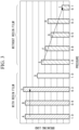
- the vertical axis of Fig. 3 represents a breaking load
- the horizontal axis represents a pressure applied to the first composite material 10 and the second composite material 20 in the pressing step.
- the pressure on the horizontal axis represents the pressure at a ratio when the reference pressure is defined as 1.0.
- bars A to D of the graph of Fig. 3 represent cases where the resin film 1 is provided between the first composite material 10 and the second composite material 20.
- a to C represent cases where the resin film 1 is provided on substantially the overall surfaces of the first fusion surface 11 and the second fusion surface 21, and D represents a case where the resin film 1 is provided on only both the ends of the first fusion surface 11 and the second fusion surface 21 (that is, only the region in a predetermined range adjacent to the space S).
- bars E to I of the graph represent cases where the resin film 1 is not provided between the first composite material 10 and the second composite material 20.
- the breaking loads in the cases where the resin film 1 is provided between the first composite material 10 and the second composite material 20 are greater than the breaking loads in the cases where the resin film 1 is not provided (bars E to I of the graph) at every pressure. Accordingly, it can be understood that the fusion strength is improved by providing the resin film 1.
- the breaking load in a case where pressurization is performed at a pressure of 1.0 (bar A of the graph) and the breaking load in a case where pressurization is performed at a pressure of 0.3 (bar C of the graph) are not significantly different from each other. Accordingly, it can be understood that, when the resin film 1 is provided, the breaking load does not significantly change even when the pressing force is reduced in the pressing step. Thus, sufficient fusion strength can be obtained even when the pressing force is reduced in the pressing step, and it can be understood that no high-pressure facility is required to be provided, which can control an increase in the facility cost.
- both the first fusion surface 11 of the first composite material 10 and the second fusion surface 21 of the second composite material 20 are machine processed surfaces applied with machine processing, but the present disclosure is not limited thereto.
- the fusion method according to the present disclosure may be applied to a case where a machine processed surface and a surface not applied with machine processing (hereinafter, referred to as "non-machine processed surface”) are fused with each other.
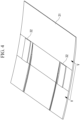
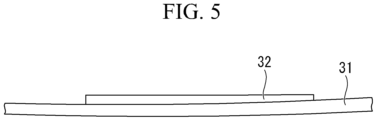
- an example of fusing a machine processed surface and a non-machine processed surface may be a case where a skin 31 formed of a composite material is fused with a spacer 32, for example.
- the spacer 32 is fixed to the surface of the skin 31 used for an aircraft.
- the skin 31 is manufactured by laminating prepreg impregnated with resin, for example.
- machine processing has not been applied to the skin 31.
- the surface of the skin 31 is a non-machine processed surface.
- the plate thickness of the skin 31 is not uniform.
- the taper processing is applied to the fusion surface (the lower surface of Fig.
- the fusion surface of the spacer 32 is a non-machine processed surface. Therefore, when the spacer 32 is fused with the surface of the skin 31, the machine processed surface and the non-machine processed surface are fused. Even in such a case, the resin film 1 is provided between the machine processed surface and the non-machine processed surface when fused, thereby resin can be further supplied to the surface of the machine processed surface, and the effect of improving fusion strength described above is thus achieved.
- an example of fusing fusion surfaces applied with the taper processing is described, but the present disclosure is not limited thereto.
- a space is formed between composite materials when fused, it is possible to reduce a defect (waviness of fibers or the like) of the composite materials due to insufficient pressurization by applying the fusion method according to the present disclosure.
- an example in which a space is formed between composite materials when fused may be a case where the fusion surface has a recess or a case where a composite material having an L-shaped cross section is fused, for example.
- a space is formed between the outer portion of a curved portion and the composite material of a counterpart portion.
- the method for applying heat and a pressure as a method for fusing the first composite material 10 and the second composite material 20 with each other is described, but the present disclosure is not limited thereto.
- the fusion method according to the present disclosure may be applied to resistance fusion.
- a composite material fusion method according to the embodiments described above will be understood as follows, for example.
- a composite material fusion method is a composite material fusion method for fusing a first composite material (10), which is a composite material made of a thermoplastic resin and fibers, and a second composite material (20), which is a composite material made of a thermoplastic resin and fibers, with each other, and the composite material fusion method includes: a resin film installation step of providing a thermoplastic resin film (1) between a machine processed surface (11) of the first composite material to be fused and a fusion surface (21) of the second composite material to be fused, the machine processed surface being applied with machine processing; a heating step of heating the first composite material and the second composite material in a state where the resin film is provided between the machine processed surface of the first composite material and the fusion surface of the second composite material; and a pressing step of pressing the first composite material and/or the second composite material in a state where the resin film is provided between the machine processed surface of the first composite material and the fusion surface of the second composite material.
- thermoplastic composite materials In fusion of thermoplastic composite materials, fusion strength is ensured by resin bonding.
- a non-machine processed surface of the composite material is in a state where fibers are covered with resin.
- fusion strength is ensured, because sufficient resin is present.
- the machine processed surface of the composite material is in a state where fibers are exposed and resin is insufficient, because the machine processing has been applied thereto.
- resin may be insufficient, and sufficient fusion strength may not be obtained.
- thermoplastic resin film is provided to the machine processed surface of the first composite material. Accordingly, the resin film is melted by heat transferred via the first composite material in the heating step. Accordingly, resin is further supplied to the machine processed surface of the first composite material. Therefore, the fusion strength can be improved compared to the case where no resin film is provided. Thus, the strength of the component after fused can be improved.
- the fusion surface of the second composite material is a machine processed surface applied with machine processing in the above first aspect.
- the fusion surface of the second composite material is also a machine processed surface. Accordingly, the resin film is installed between the machine processed surface of the first composite material and the machine processed surface of the second composite material. Therefore, the melted resin film enables the resin to be further supplied to both the machine processed surface of the first composite material and the machine processed surface of the second composite material. Therefore, the fusion strength can be improved even when machine processed surfaces where fusion strength is likely to decrease are fused with each other. Thus, the strength of the component after fused can be improved.
- a composite material fusion method is a composite material fusion method for fusing a first composite material (10), which is a composite material made of a thermoplastic resin and fibers, and a second composite material (20), which is a composite material made of a thermoplastic resin and fibers, with each other, the composite material fusion method includes: a resin film installation step of providing a resin film (1) between a first fusion surface (11) of the first composite material to be fused and a second fusion surface (21) of the second composite material (20) to be fused; a heating step of heating the first composite material and the second composite material in a state where the resin film is provided between the first fusion surface of the first composite material and the second fusion surface of the second composite material; and a pressing step of pressing the first composite material and/or the second composite material in a state where the resin film is provided between the first fusion surface of the first composite material and the second fusion surface of the second composite material, and the resin film is installed so as to face a space formed between the first composite material (10), which is
- the resin film is installed so as to face the space formed between the first composite material and the second composite material. This causes the resin film melted in the heating step to flow into the space. Accordingly, the space is filled with resin. Therefore, in the pressing step, it is possible to preferably apply a pressure to a surface facing the space via the filled resin. Thus, a defect (waviness of fibers or the like) of the composite materials due to insufficient pressurization can be reduced. This can improve the strength of the component after fused.
- a resin in the first composite material and a resin in the resin film are the same resin in any one of the first aspect to the third aspect described above.
- the melted resin film and the first composite material are integrated. This enables more preferable fusion between the first composite material and the second composite material.
Landscapes
- Engineering & Computer Science (AREA)
- Mechanical Engineering (AREA)
- Physics & Mathematics (AREA)
- Fluid Mechanics (AREA)
- Lining Or Joining Of Plastics Or The Like (AREA)
- Moulding By Coating Moulds (AREA)
Abstract
Description
- The present disclosure relates to a composite material fusion method.
- Aircraft components such as a fuselage or a main wing of an aircraft may use a composite material such as Carbon Fiber Reinforced Thermo Plastics (CFRTP). A known technique is to fuse and thus join components formed of such a thermoplastic composite material with each other (as in, for example,
Japanese Patent No. 6990343 -
Japanese Patent No. 6990343 -
Japanese Patent No. 6990343 - Examples of methods for fusing composite material components with each other include a method for applying machine processing to a fusion surface of each composite material into a tapered shape and fusing the machine processed surfaces with each other (that is, a taper splice j oint). In this method, it is not possible to apply taper processing to the end of a fusion surface because of limited machine processing accuracy, and therefore a space between the composite materials at the end is undesirably formed when the fusion surfaces of the composite materials are attached to each other. Once the space is formed, an insufficient pressure may be applied to portions facing the space of the composite materials. When it is not possible to apply a sufficient pressure, such portions will remain as unpressed portions. The unpressed portions cause waviness of fibers in the melted resin, and this may cause an internal defect (such as wrinkle or delamination). Occurrence of an internal defect may reduce the strength of a component after fused. Note that such a problem may arise not only in the case of the taper splice joint but also in a case where the space is formed between the composite materials.
- Further, in fusion of thermoplastic composite materials, fusion strength is ensured by resin bonding. A non-machine processed surface of the composite material is in a state where fibers are covered with the resin. Thus, when non-machine processed surfaces are fused, fusion strength is ensured, because sufficient resin is present. In contrast, a machine processed surface of the composite material is in a state where fibers are exposed and resin is insufficient, because the machine processing has been applied thereto. Thus, when machine processed surfaces are fused, resin may be insufficient, and sufficient fusion strength may not be obtained. Accordingly, a method for fusing machine processed surfaces with each other may reduce strength of a component after fused. Note that such a problem may arise not only in the case of the taper splice joint but also in a case where any one of the fusion surfaces is a machine processed surface.
- The present disclosure has been made in view of such circumstances, and an object is to provide a composite material fusion method that can improve strength of a component after fused.
- To achieve the above object, the composite material fusion method of the present disclosure employs the following solutions.
- A composite material fusion method according to one aspect of the present disclosure is a composite material fusion method for fusing a first composite material, which is a composite material made of a thermoplastic resin and fibers, and a second composite material, which is a composite material made of a thermoplastic resin and fibers, with each other, and the composite material fusion method includes: a resin film installation step of providing a thermoplastic resin film between a machine processed surface of the first composite material to be fused and a fusion surface of the second composite material to be fused, the machine processed surface being applied with machine processing; a heating step of heating the first composite material and the second composite material in a state where the resin film is provided between the machine processed surface of the first composite material and the fusion surface of the second composite material; and a pressing step of pressing the first composite material and/or the second composite material in a state where the resin film is provided between the machine processed surface of the first composite material and the fusion surface of the second composite material.
- According to the present disclosure, the strength of a component after fused can be improved.
-
-
Fig. 1 is a diagram illustrating a composite material fusion method according to an embodiment of the present disclosure, which is a longitudinal sectional view of a first composite material and a second composite material in a state where a resin film is interposed therebetween. -
Fig. 2 is an enlarged view of a main portion (portion II) ofFig. 1 . -
Fig. 3 is a graph illustrating an effect of improving fusion strength in the composite material fusion method according to the embodiment of the present disclosure. -
Fig. 4 is a perspective view illustrating a component in which a spacer is fused to a skin by using the composite material fusion method according to the embodiment of the present disclosure. -
Fig. 5 is a diagram viewed from the arrow direction of the V-V line ofFig. 4 . - One embodiment of a composite material fusion method according to the present disclosure will be described below with reference to the drawings.
- The fusion method according to the present embodiment is used to fuse members with each other that are formed of a composite material used as a material for manufacturing a stringer, a spar, a frame, a rib, and the like that are aircraft components forming an aircraft structure. An example of the composite material (a first
composite material 10 and a second composite material 20) to be fused may be Carbon Fiber Reinforced Thermo Plastics (CFRTP) of compounded thermoplastic resin and fibers. Specifically, the composite material may be a laminated body of a plurality of laminated fiber reinforced sheets having fibers impregnated with resin. - In the present embodiment, an example of fusing the first
composite material 10 and the secondcomposite material 20 with each other will be described. - First, the shapes of the first
composite material 10 and the secondcomposite material 20 and the arrangement of aresin film 1 will be described with reference toFig. 1 andFig. 2 . Note that, inFig. 1 andFig. 2 , theresin film 1 is illustrated thicker than theactual resin film 1 for emphasis. Further, inFig. 1 andFig. 2 , a space S is illustrated larger than the actual space S for emphasis. - As illustrated in
Fig. 1 , the firstcomposite material 10 and the secondcomposite material 20 have the same shape and are arranged to be point symmetrical. The firstcomposite material 10 and the secondcomposite material 20 are formed by cutting a flat plate-like laminated body by using a cutting device. - The first
composite material 10 has a tapered first fusion surface (a machine processed surface) 11. The firstcomposite material 10 has two plane surfaces connected via thefirst fusion surface 11. In the following description, out of the two plane surfaces, a surface on the upper side of a drawing sheet is referred to as anupper surface 12, and a surface on the lower side of the drawing sheet is referred to as alower surface 13. Thefirst fusion surface 11 is formed to be inclined with respect to theupper surface 12 and thelower surface 13. - The second
composite material 20 has a taperedsecond fusion surface 21. The secondcomposite material 20 has two plane surfaces connected via thesecond fusion surface 21. In the following description, out of the two plane surfaces, a surface on the upper side of the drawing sheet is referred to as anupper surface 22, and a surface on the lower side of the drawing sheet is referred to as alower surface 23. Thesecond fusion surface 21 is formed to be inclined with respect to theupper surface 22 and thelower surface 23. - The
first fusion surface 11 and thesecond fusion surface 21 are formed by cutting a flat plate-like laminated body, as described above. In such a way, machine processing is applied to thefirst fusion surface 11 of the firstcomposite material 10 and thesecond fusion surface 21 of the secondcomposite material 20. In the following description, a surface applied with machine processing is referred to as "machine processed surface". The machine processing is processing (for example, cutting or milling) using a machine. Specifically, an example of the machine processing may be processing of cutting off a workpiece (in the present embodiment, the laminated body), processing of milling a workpiece, or the like by a blade, a water jet, ultrasonic waves, or the like. Further, the machine processed surface is a surface on which machine processing is performed, so that fibers are more exposed than other surfaces. In the present embodiment, thefirst fusion surface 11 and thesecond fusion surface 21 are machine processed surfaces. - The taper processing on the
first fusion surface 11 does not reach one end (the lower end in the present embodiment) because of limited machine processing accuracy. Anend plane surface 14 substantially orthogonal to thelower surface 13 is formed on one end of thefirst fusion surface 11. Thefirst fusion surface 11 and thelower surface 13 are connected via theend plane surface 14. - As illustrated in
Fig. 2 , the taper processing on thesecond fusion surface 21 does not reach one end (the upper end in the present embodiment) because of limited machine processing accuracy. Anend plane surface 24 substantially orthogonal to theupper surface 22 is formed on one end of thesecond fusion surface 21. Thesecond fusion surface 21 and theupper surface 22 are connected via theend plane surface 24. - As illustrated in
Fig. 1 , when fused, the firstcomposite material 10 and the secondcomposite material 20 are arranged so that thefirst fusion surface 11 and thesecond fusion surface 21 are in contact with each other (in detail, in contact with each other via theresin film 1 described later). At this time, as illustrated inFig. 1 andFig. 2 , the space S is formed between the firstcomposite material 10 and the secondcomposite material 20. In detail, the space S is formed between thefirst fusion surface 11 of the firstcomposite material 10 and theend plane surface 24 of the secondcomposite material 20. Further, the space S is formed between thesecond fusion surface 21 of the secondcomposite material 20 and theend plane surface 14 of the firstcomposite material 10. The space S is substantially triangular in the longitudinal cross section. The space S is formed to be recessed from theupper surface 12 of the firstcomposite material 10 and theupper surface 22 of the secondcomposite material 20. Further, the space S is formed to be recessed from thelower surface 13 of the firstcomposite material 10 and thelower surface 23 of the secondcomposite material 20. - When the first
composite material 10 and the secondcomposite material 20 are fused with each other, theresin film 1 is provided between thefirst fusion surface 11 and thesecond fusion surface 21. - The
resin film 1 is formed of a thermoplastic resin. Theresin film 1 is formed of poly(aryl ether ketone) (PAEK), poly(ether ether ketone) (PEEK), or the like. Note that theresin film 1 is formed of the same resin as the resin contained in the firstcomposite material 10 and the secondcomposite material 20. - The thickness of the
resin film 1 is greater than or equal to 50 µm and less than or equal to 250 µm. Further, theresin film 1 may be formed of a single film or may be formed of multiple films. When multiple films are provided, the total thickness of themultiple resin films 1 is greater than or equal to 50 µm and less than or equal to 250 µm. - When the first
composite material 10 and the secondcomposite material 20 are fused with each other, theresin film 1 covers the overall region of thefirst fusion surface 11 and thesecond fusion surface 21 in the depth direction of the drawing sheet ofFig. 1 . In the present embodiment, theresin film 1 is not arranged in the space S. Theresin film 1 covers a region adjacent to a region facing the space S in thefirst fusion surface 11 and thesecond fusion surface 21. Note that theresin film 1 may be arranged in the space S; that is, theresin film 1 may cover a region facing the space S. - The
resin film 1 faces the space S. In detail, the end face of theresin film 1 faces the space S. - Next, the fusion method or the like according to the present embodiment will be described.
- First, the first
composite material 10 and the secondcomposite material 20 are manufactured by cutting a flat plate-like laminated body by using a cutting machine so that the flat plate-like laminated body is inclined with respect to a plate surface. Accordingly, thefirst fusion surface 11 and thesecond fusion surface 21 that are the cut surfaces become machine processed surfaces. - Next, as described above, the first
composite material 10 and the secondcomposite material 20 are arranged so that thefirst fusion surface 11 and thesecond fusion surface 21 are in contact with each other via theresin film 1. In other words, theresin film 1 is provided between thefirst fusion surface 11 and the second fusion surface 21 (in a resin film installation step). Accordingly, theresin film 1 is interposed between thefirst fusion surface 11 and thesecond fusion surface 21. At this time, two spaces S are formed between the firstcomposite material 10 and the secondcomposite material 20. - Next, a pair of
heaters 2 are arranged so as to interpose the firstcomposite material 10 and the secondcomposite material 20. In detail, one of theheaters 2 is provided to be in contact with theupper surface 12 of the firstcomposite material 10 and theupper surface 22 of the secondcomposite material 20. Further, theother heater 2 is provided to be in contact with thelower surface 13 of the firstcomposite material 10 and thelower surface 23 of the secondcomposite material 20. - At this time, the pair of
heaters 2 are arranged so that thefirst fusion surface 11 and thesecond fusion surface 21 are located between the pair ofheaters 2. - Next, the temperature of the
heater 2 is elevated, thereby heating the firstcomposite material 10 and the secondcomposite material 20 with theresin film 1 being provided between thefirst fusion surface 11 of the firstcomposite material 10 and thesecond fusion surface 21 of the second composite material 20 (in a heating step). In detail, the firstcomposite material 10 and the secondcomposite material 20 are heated above the melting point of the resin contained in the firstcomposite material 10 and the secondcomposite material 20. Accordingly, the resin contained in the firstcomposite material 10 and the secondcomposite material 20 is melted. At this time, theresin film 1 is also heated via the firstcomposite material 10 and the secondcomposite material 20 and thus melted. - Next, the first
composite material 10 and the secondcomposite material 20 with theresin film 1 being provided between thefirst fusion surface 11 of the firstcomposite material 10 and thesecond fusion surface 21 of the secondcomposite material 20 are pressed to be held by the pair of heaters 2 (in a pressing step). - In the heating step and the pressing step, the melted
resin film 1 flows into the space S as indicated by the arrow A ofFig. 2 . Accordingly, the space S is filled with the meltedresin film 1. Thus, in the pressing step, the pressure is applied even to the region facing the space S via the filled resin. - The temperature of the
heater 2 is reduced in a pressed state to cool the firstcomposite material 10 and the secondcomposite material 20. Accordingly, the firstcomposite material 10 and the secondcomposite material 20 are solidified, and thefirst fusion surface 11 of the firstcomposite material 10 and thesecond fusion surface 21 of the secondcomposite material 20 are fused with each other. - In such a way, in the present embodiment, the first
composite material 10 and the secondcomposite material 20 are joined by the taper splice joint. - According to the present embodiment, the following advantageous effects are achieved.
- In fusion of thermoplastic composite materials, fusion strength is ensured by resin bonding. The non-machine processed surface of the composite material is in a state where fibers are covered with resin. Thus, in fusion of the non-machine processed surfaces, fusion strength is ensured, because sufficient resin is present. In contrast, the machine processed surface of the composite material is in a state where fibers are exposed and resin is insufficient, because the machine processing has been applied thereto. Thus, in fusion of the machine processed surface, resin may be insufficient, and sufficient strength may not be obtained.
- In the present embodiment, in a resin film installation step, the
thermoplastic resin film 1 is provided to the machine processed surface (first fusion surface 11) of the firstcomposite material 10. Accordingly, theresin film 1 is melted by heat transferred via the firstcomposite material 10 in the heating step. Accordingly, resin is further supplied to the machine processed surface of the firstcomposite material 10. Therefore, the fusion strength can be improved compared to the case where theresin film 1 is not provided. Thus, the strength of the component after fused can be improved. - In the present embodiment, the
second fusion surface 21 of the secondcomposite material 20 is also a machine processed surface. Accordingly, theresin film 1 is installed between the machine processed surface of the firstcomposite material 10 and the machine processed surface of the secondcomposite material 20. Therefore, the meltedresin film 1 enables the resin to be further supplied to both the machine processed surface of the firstcomposite material 10 and the machine processed surface of the secondcomposite material 20. Therefore, the fusion strength can be improved even when machine processed surfaces where fusion strength is likely to decrease are fused with each other. Thus, the strength of the component after fused can be improved. - When a space is formed between the first
composite material 10 and the secondcomposite material 20, a portion facing the space S in the firstcomposite material 10 and the secondcomposite material 20 may be insufficiently pressed in the pressing step. When it is not possible to apply a sufficient pressure in the pressing step, waviness of fibers may occur in the melted resin in the firstcomposite material 10 and the secondcomposite material 20. - In the present embodiment, the
resin film 1 is installed so as to face the space S formed between the firstcomposite material 10 and the secondcomposite material 20. This causes theresin film 1 melted in the heating step to flow into the space S. Accordingly, the space S is filled with resin. Therefore, in the pressing step, it is possible to preferably apply a pressure to the surface facing the space S via the filled resin. This can reduce a defect (waviness of fibers or the like) of the composite materials due to insufficient pressurization and improve the strength of the component after fused. - Further, in a state where the space S is not filled with resin, a step part is formed in a connection portion between the
first fusion surface 11 and theend plane surface 14 of the firstcomposite material 10. Further, a step part is formed in a connection portion between thesecond fusion surface 21 and theend plane surface 24 of the secondcomposite material 20. The presence of such step parts may cause the stress peak at the step parts, which may lead to a reduction in fusion strength. - In the present embodiment, the space S is filled with resin in the heating step and the pressing step, and thus no step part is present in the
first fusion surface 11 of the firstcomposite material 10 and thesecond fusion surface 21 of the secondcomposite material 20. Accordingly, the stress peak at the step part can be decreased. Therefore, a reduction in strength can be controlled. - When the
resin film 1 is not provided between the fusion surfaces, the fusion strength is low, and thus a high pressure is required as the pressing force in the pressing step in order to obtain desired fusion strength. This may increase the facility cost. - In contrast, in the present embodiment, the
resin film 1 is provided between the fusion surfaces, and thus sufficient fusion strength can be obtained even at a relatively low pressure. Therefore, an increase in the facility cost can be controlled. - Further, in the present embodiment, the resin contained in the first
composite material 10 and the secondcomposite material 20 and the resin of theresin film 1 are the same. Accordingly, the meltedresin film 1 and the firstcomposite material 10 and the secondcomposite material 20 are integrated. This enables more preferable fusion between the firstcomposite material 10 and the secondcomposite material 20. - The effect of improving the fusion strength or the like described above will be described in detail with reference to
Fig. 3 . The vertical axis ofFig. 3 represents a breaking load, and the horizontal axis represents a pressure applied to the firstcomposite material 10 and the secondcomposite material 20 in the pressing step. The pressure on the horizontal axis represents the pressure at a ratio when the reference pressure is defined as 1.0. - Further, bars A to D of the graph of
Fig. 3 represent cases where theresin film 1 is provided between the firstcomposite material 10 and the secondcomposite material 20. Note that, as with the above description, A to C represent cases where theresin film 1 is provided on substantially the overall surfaces of thefirst fusion surface 11 and thesecond fusion surface 21, and D represents a case where theresin film 1 is provided on only both the ends of thefirst fusion surface 11 and the second fusion surface 21 (that is, only the region in a predetermined range adjacent to the space S). Further, bars E to I of the graph represent cases where theresin film 1 is not provided between the firstcomposite material 10 and the secondcomposite material 20. - As can be seen from
Fig. 3 , the breaking loads in the cases where theresin film 1 is provided between the firstcomposite material 10 and the second composite material 20 (bars A to D of the graph) are greater than the breaking loads in the cases where theresin film 1 is not provided (bars E to I of the graph) at every pressure. Accordingly, it can be understood that the fusion strength is improved by providing theresin film 1. - Further, the breaking load in a case where pressurization is performed at a pressure of 1.0 (bar A of the graph) and the breaking load in a case where pressurization is performed at a pressure of 0.3 (bar C of the graph) are not significantly different from each other. Accordingly, it can be understood that, when the
resin film 1 is provided, the breaking load does not significantly change even when the pressing force is reduced in the pressing step. Thus, sufficient fusion strength can be obtained even when the pressing force is reduced in the pressing step, and it can be understood that no high-pressure facility is required to be provided, which can control an increase in the facility cost. - In contrast, it can be understood that, when the
resin film 1 is not provided, a reduction in the pressure tends to reduce the breaking load, and in such a case, a high pressure is required as the pressing force in the pressing step in order to obtain desired fusion strength, thereby increasing the facility cost. - Further, as can be seen from comparison between a case (bar A of the graph) where the
resin film 1 is provided on substantially the overall surfaces of thefirst fusion surface 11 and thesecond fusion surface 21 and pressurization is performed at a pressure of 1.0, a case (bar D of the graph) where theresin film 1 is provided at only both the ends of thefirst fusion surface 11 and thesecond fusion surface 21 and pressurization is performed at a pressure of 1.0, and a case (bar E of the graph) where theresin film 1 is not provided and pressurization is performed at a pressure of 1.0, a difference in breaking loads between bar A and bar D of the graph is greater than a difference in breaking loads between bar D and bar E of the graph. Accordingly, it can be understood that an effect of further supplying resin to a machine processed surface via theresin film 1 has a greater effect on improvement of fusion strength than an effect of filling the space S with resin. - Note that the present disclosure is not limited to the embodiments described above and can be changed as appropriate within the scope not departing from the spirit of the present disclosure.
- For example, in the above embodiment, both the
first fusion surface 11 of the firstcomposite material 10 and thesecond fusion surface 21 of the secondcomposite material 20 are machine processed surfaces applied with machine processing, but the present disclosure is not limited thereto. For example, the fusion method according to the present disclosure may be applied to a case where a machine processed surface and a surface not applied with machine processing (hereinafter, referred to as "non-machine processed surface") are fused with each other. - As illustrated in
Fig. 4 andFig. 5 , an example of fusing a machine processed surface and a non-machine processed surface may be a case where askin 31 formed of a composite material is fused with aspacer 32, for example. As illustrated inFig. 4 , thespacer 32 is fixed to the surface of theskin 31 used for an aircraft. Theskin 31 is manufactured by laminating prepreg impregnated with resin, for example. Thus, machine processing has not been applied to theskin 31. Thus, the surface of theskin 31 is a non-machine processed surface. In contrast, as illustrated inFig. 5 , the plate thickness of theskin 31 is not uniform. Thus, the taper processing is applied to the fusion surface (the lower surface ofFig. 5 ) of thespacer 32 so that thespacer 32 corresponds to the plate thickness of theskin 31. Thus, the fusion surface of thespacer 32 is a non-machine processed surface. Therefore, when thespacer 32 is fused with the surface of theskin 31, the machine processed surface and the non-machine processed surface are fused. Even in such a case, theresin film 1 is provided between the machine processed surface and the non-machine processed surface when fused, thereby resin can be further supplied to the surface of the machine processed surface, and the effect of improving fusion strength described above is thus achieved. - Further, in the above embodiment, an example of fusing fusion surfaces applied with the taper processing is described, but the present disclosure is not limited thereto. When a space is formed between composite materials when fused, it is possible to reduce a defect (waviness of fibers or the like) of the composite materials due to insufficient pressurization by applying the fusion method according to the present disclosure. For example, an example in which a space is formed between composite materials when fused may be a case where the fusion surface has a recess or a case where a composite material having an L-shaped cross section is fused, for example. When a composite material having an L-shaped cross section is fused, a space is formed between the outer portion of a curved portion and the composite material of a counterpart portion.
- Further, in the above embodiment, the method for applying heat and a pressure as a method for fusing the first
composite material 10 and the secondcomposite material 20 with each other is described, but the present disclosure is not limited thereto. For example, the fusion method according to the present disclosure may be applied to resistance fusion. - A composite material fusion method according to the embodiments described above will be understood as follows, for example.
- A composite material fusion method according to the first aspect of the present disclosure is a composite material fusion method for fusing a first composite material (10), which is a composite material made of a thermoplastic resin and fibers, and a second composite material (20), which is a composite material made of a thermoplastic resin and fibers, with each other, and the composite material fusion method includes: a resin film installation step of providing a thermoplastic resin film (1) between a machine processed surface (11) of the first composite material to be fused and a fusion surface (21) of the second composite material to be fused, the machine processed surface being applied with machine processing; a heating step of heating the first composite material and the second composite material in a state where the resin film is provided between the machine processed surface of the first composite material and the fusion surface of the second composite material; and a pressing step of pressing the first composite material and/or the second composite material in a state where the resin film is provided between the machine processed surface of the first composite material and the fusion surface of the second composite material.
- In fusion of thermoplastic composite materials, fusion strength is ensured by resin bonding. A non-machine processed surface of the composite material is in a state where fibers are covered with resin. Thus, in fusion of the non-machine processed surface, fusion strength is ensured, because sufficient resin is present. In contrast, the machine processed surface of the composite material is in a state where fibers are exposed and resin is insufficient, because the machine processing has been applied thereto. Thus, when the machine processed surfaces are fused with each other, resin may be insufficient, and sufficient fusion strength may not be obtained.
- In the above configuration, in the resin film installation step, the thermoplastic resin film is provided to the machine processed surface of the first composite material. Accordingly, the resin film is melted by heat transferred via the first composite material in the heating step. Accordingly, resin is further supplied to the machine processed surface of the first composite material. Therefore, the fusion strength can be improved compared to the case where no resin film is provided. Thus, the strength of the component after fused can be improved.
- In a composite material fusion method according to the second aspect of the present disclosure, the fusion surface of the second composite material is a machine processed surface applied with machine processing in the above first aspect.
- In the above configuration, the fusion surface of the second composite material is also a machine processed surface. Accordingly, the resin film is installed between the machine processed surface of the first composite material and the machine processed surface of the second composite material. Therefore, the melted resin film enables the resin to be further supplied to both the machine processed surface of the first composite material and the machine processed surface of the second composite material. Therefore, the fusion strength can be improved even when machine processed surfaces where fusion strength is likely to decrease are fused with each other. Thus, the strength of the component after fused can be improved.
- A composite material fusion method according to the third aspect of the present disclosure is a composite material fusion method for fusing a first composite material (10), which is a composite material made of a thermoplastic resin and fibers, and a second composite material (20), which is a composite material made of a thermoplastic resin and fibers, with each other, the composite material fusion method includes: a resin film installation step of providing a resin film (1) between a first fusion surface (11) of the first composite material to be fused and a second fusion surface (21) of the second composite material (20) to be fused; a heating step of heating the first composite material and the second composite material in a state where the resin film is provided between the first fusion surface of the first composite material and the second fusion surface of the second composite material; and a pressing step of pressing the first composite material and/or the second composite material in a state where the resin film is provided between the first fusion surface of the first composite material and the second fusion surface of the second composite material, and the resin film is installed so as to face a space formed between the first composite material and the second composite material in the resin film installation step.
- When a space is formed between the first composite material and the second composite material, a portion facing the space in the first composite material and the second composite material may be insufficiently pressed in the pressing step. When it is not possible to apply a sufficient pressure in the pressing step, waviness of fibers may occur in the melted resin in the first composite material and the second composite material.
- In the above configuration, the resin film is installed so as to face the space formed between the first composite material and the second composite material. This causes the resin film melted in the heating step to flow into the space. Accordingly, the space is filled with resin. Therefore, in the pressing step, it is possible to preferably apply a pressure to a surface facing the space via the filled resin. Thus, a defect (waviness of fibers or the like) of the composite materials due to insufficient pressurization can be reduced. This can improve the strength of the component after fused.
- In a composite material fusion method according to the fourth aspect of the present disclosure, a resin in the first composite material and a resin in the resin film are the same resin in any one of the first aspect to the third aspect described above.
- In the above configuration, the melted resin film and the first composite material are integrated. This enables more preferable fusion between the first composite material and the second composite material.
-
- 1
- resin film
- 2
- heater
- 10
- first composite material
- 11
- first fusion surface
- 12
- upper surface
- 13
- lower surface
- 14
- end plane surface
- 20
- second composite material
- 21
- second fusion surface
- 22
- upper surface
- 23
- lower surface
- 24
- end plane surface
- 31
- skin
- 32
- spacer
- S
- space
Claims (4)
- A composite material fusion method for fusing a first composite material, which is a composite material made of a thermoplastic resin and fibers, and a second composite material, which is a composite material made of a thermoplastic resin and fibers, with each other, the composite material fusion method comprising:a resin film installation step of providing a thermoplastic resin film between a machine processed surface of the first composite material to be fused and a fusion surface of the second composite material to be fused, the machine processed surface being applied with machine processing;a heating step of heating the first composite material and the second composite material in a state where the resin film is provided between the machine processed surface of the first composite material and the fusion surface of the second composite material; anda pressing step of pressing the first composite material and/or the second composite material in a state where the resin film is provided between the machine processed surface of the first composite material and the fusion surface of the second composite material.
- The composite material fusion method according to claim 1, wherein the fusion surface of the second composite material is a machine processed surface applied with machine processing.
- A composite material fusion method for fusing a first composite material, which is a composite material made of a thermoplastic resin and fibers, and a second composite material, which is a composite material made of a thermoplastic resin and fibers, with each other, the composite material fusion method comprising:a resin film installation step of providing a resin film between a first fusion surface of the first composite material to be fused and a second fusion surface of the second composite material to be fused;a heating step of heating the first composite material and the second composite material in a state where the resin film is provided between the first fusion surface of the first composite material and the second fusion surface of the second composite material; anda pressing step of pressing the first composite material and/or the second composite material in a state where the resin film is provided between the first fusion surface of the first composite material and the second fusion surface of the second composite material,wherein the resin film is installed so as to face a space formed between the first composite material and the second composite material in the resin film installation step.
- The composite material fusion method according to any one of claims 1 to 3, wherein a resin in the first composite material and a resin in the resin film are the same resin.
Applications Claiming Priority (1)
| Application Number | Priority Date | Filing Date | Title |
|---|---|---|---|
| JP2022067676A JP7761523B2 (en) | 2022-04-15 | 2022-04-15 | Fusion bonding of composite materials |
Publications (1)
| Publication Number | Publication Date |
|---|---|
| EP4261020A1 true EP4261020A1 (en) | 2023-10-18 |
Family
ID=85018751
Family Applications (1)
| Application Number | Title | Priority Date | Filing Date |
|---|---|---|---|
| EP23152433.1A Pending EP4261020A1 (en) | 2022-04-15 | 2023-01-19 | Composite material fusion method |
Country Status (3)
| Country | Link |
|---|---|
| US (1) | US20230330972A1 (en) |
| EP (1) | EP4261020A1 (en) |
| JP (1) | JP7761523B2 (en) |
Citations (3)
| Publication number | Priority date | Publication date | Assignee | Title |
|---|---|---|---|---|
| JPH0690343B2 (en) | 1983-09-14 | 1994-11-14 | 古河電気工業株式会社 | Method for forming reinforced fiber connection |
| US20130287481A1 (en) * | 2012-04-26 | 2013-10-31 | Richard Hardy | Method for thermoplastic welding and welded composite structures |
| US9829068B2 (en) * | 2016-01-14 | 2017-11-28 | Uniband USA, LLC | Seamless end connection for conveyor belts |
Family Cites Families (7)
| Publication number | Priority date | Publication date | Assignee | Title |
|---|---|---|---|---|
| JPH04179535A (en) * | 1990-11-14 | 1992-06-26 | Yokohama Rubber Co Ltd:The | Method for endless processing of resin belt |
| US5717191A (en) * | 1995-06-06 | 1998-02-10 | The Boeing Company | Structural susceptor for thermoplastic welding |
| CN101394988B (en) * | 2006-03-15 | 2010-09-29 | 东丽株式会社 | Preform manufacturing method and manufacturing device |
| JP2007253347A (en) * | 2006-03-20 | 2007-10-04 | Ricoh Co Ltd | Joining member manufacturing method, endless joining belt, fixing unit, intermediate transfer unit, image forming apparatus, and sheet joining apparatus |
| US9694560B2 (en) * | 2008-06-23 | 2017-07-04 | The Boeing Company | Multi-layer film adhesive |
| JP2014076565A (en) * | 2012-10-10 | 2014-05-01 | Toray Ind Inc | Fiber reinforced thermoplastics joined body, and joining method therefor |
| JP7263621B2 (en) * | 2020-03-31 | 2023-04-24 | 三菱重工業株式会社 | Joining method |
-
2022
- 2022-04-15 JP JP2022067676A patent/JP7761523B2/en active Active
-
2023
- 2023-01-17 US US18/097,553 patent/US20230330972A1/en active Pending
- 2023-01-19 EP EP23152433.1A patent/EP4261020A1/en active Pending
Patent Citations (3)
| Publication number | Priority date | Publication date | Assignee | Title |
|---|---|---|---|---|
| JPH0690343B2 (en) | 1983-09-14 | 1994-11-14 | 古河電気工業株式会社 | Method for forming reinforced fiber connection |
| US20130287481A1 (en) * | 2012-04-26 | 2013-10-31 | Richard Hardy | Method for thermoplastic welding and welded composite structures |
| US9829068B2 (en) * | 2016-01-14 | 2017-11-28 | Uniband USA, LLC | Seamless end connection for conveyor belts |
Also Published As
| Publication number | Publication date |
|---|---|
| JP7761523B2 (en) | 2025-10-28 |
| US20230330972A1 (en) | 2023-10-19 |
| JP2023157640A (en) | 2023-10-26 |
Similar Documents
| Publication | Publication Date | Title |
|---|---|---|
| US5919413A (en) | Method for inserting Z-pins | |
| US6436507B1 (en) | Composites joined with z-pin reinforcement | |
| EP3681703B1 (en) | Conduction welding | |
| US5980665A (en) | Z-pin reinforced bonds for connecting composite structures | |
| US5556565A (en) | Method for composite welding using a hybrid metal webbed composite beam | |
| US5829716A (en) | Welded aerospace structure using a hybrid metal webbed composite beam | |
| US5688426A (en) | Hybrid metal webbed composite beam | |
| US9827710B2 (en) | Radius filler and method of manufacturing same | |
| JP6581770B2 (en) | Hybrid laminate and molded composite structure | |
| EP2977192B1 (en) | Fabric jacketed unidirectional noodle and its method of construction | |
| EP2790891B1 (en) | Thermoplastic injection molded element with integral thermoplastic positioning system for reinforced composite structures | |
| CN104822511A (en) | Joining composite components using low temperature thermoplastic film fusion | |
| US11813802B2 (en) | Methods of joining and repairing composite components | |
| US11413828B2 (en) | Aircraft blade and methods of forming and repairing an aircraft blade | |
| EP3769948B1 (en) | Composite structure having thermoplastic radius filler | |
| US20140023830A1 (en) | Method of manufacturing a structure | |
| Engelhardt et al. | In situ joining of unidirectional tapes on long fiber reinforced thermoplastic structures by thermoplastic automated fiber placement for scientific sounding rocket applications | |
| US20230330972A1 (en) | Composite material fusion method | |
| EP3409446B1 (en) | Method of creating large complex composite panels using co-consolidation of thermoplastic material subpanels | |
| US6602810B1 (en) | Method for alleviating residual tensile strain in thermoplastic welds | |
| US10987877B2 (en) | Method for producing a vehicle component from a fiber-reinforced plastic | |
| EP0261850A2 (en) | Joining fibre reinforced thermoplastic materials | |
| WO1996040551A1 (en) | Hybrid metal webbed composite beam | |
| JP7230110B2 (en) | Joining method | |
| CN115709568A (en) | Heating element and welding kit and method for manufacturing heating element and welded component |
Legal Events
| Date | Code | Title | Description |
|---|---|---|---|
| PUAI | Public reference made under article 153(3) epc to a published international application that has entered the european phase |
Free format text: ORIGINAL CODE: 0009012 |
|
| STAA | Information on the status of an ep patent application or granted ep patent |
Free format text: STATUS: THE APPLICATION HAS BEEN PUBLISHED |
|
| AK | Designated contracting states |
Kind code of ref document: A1 Designated state(s): AL AT BE BG CH CY CZ DE DK EE ES FI FR GB GR HR HU IE IS IT LI LT LU LV MC ME MK MT NL NO PL PT RO RS SE SI SK SM TR |
|
| STAA | Information on the status of an ep patent application or granted ep patent |
Free format text: STATUS: REQUEST FOR EXAMINATION WAS MADE |
|
| 17P | Request for examination filed |
Effective date: 20240416 |
|
| RBV | Designated contracting states (corrected) |
Designated state(s): AL AT BE BG CH CY CZ DE DK EE ES FI FR GB GR HR HU IE IS IT LI LT LU LV MC ME MK MT NL NO PL PT RO RS SE SI SK SM TR |
|
| STAA | Information on the status of an ep patent application or granted ep patent |
Free format text: STATUS: EXAMINATION IS IN PROGRESS |
|
| 17Q | First examination report despatched |
Effective date: 20241004 |
|
| RIC1 | Information provided on ipc code assigned before grant |
Ipc: B29C 65/48 20060101AFI20260129BHEP Ipc: B29C 65/50 20060101ALI20260129BHEP Ipc: B29C 65/18 20060101ALI20260129BHEP Ipc: B29L 31/30 20060101ALN20260129BHEP |
|
| GRAP | Despatch of communication of intention to grant a patent |
Free format text: ORIGINAL CODE: EPIDOSNIGR1 |
|
| STAA | Information on the status of an ep patent application or granted ep patent |
Free format text: STATUS: GRANT OF PATENT IS INTENDED |
|
| INTG | Intention to grant announced |
Effective date: 20260312 |