EP4261019A1 - Method, plant and tool device for processing profiled bars - Google Patents
Method, plant and tool device for processing profiled bars Download PDFInfo
- Publication number
- EP4261019A1 EP4261019A1 EP23167559.6A EP23167559A EP4261019A1 EP 4261019 A1 EP4261019 A1 EP 4261019A1 EP 23167559 A EP23167559 A EP 23167559A EP 4261019 A1 EP4261019 A1 EP 4261019A1
- Authority
- EP
- European Patent Office
- Prior art keywords
- profiled bar
- seal
- tool
- rotary tool
- profiled
- Prior art date
- Legal status (The legal status is an assumption and is not a legal conclusion. Google has not performed a legal analysis and makes no representation as to the accuracy of the status listed.)
- Granted
Links
Images


Classifications
-
- B—PERFORMING OPERATIONS; TRANSPORTING
- B29—WORKING OF PLASTICS; WORKING OF SUBSTANCES IN A PLASTIC STATE IN GENERAL
- B29C—SHAPING OR JOINING OF PLASTICS; SHAPING OF MATERIAL IN A PLASTIC STATE, NOT OTHERWISE PROVIDED FOR; AFTER-TREATMENT OF THE SHAPED PRODUCTS, e.g. REPAIRING
- B29C65/00—Joining or sealing of preformed parts, e.g. welding of plastics materials; Apparatus therefor
- B29C65/02—Joining or sealing of preformed parts, e.g. welding of plastics materials; Apparatus therefor by heating, with or without pressure
- B29C65/18—Joining or sealing of preformed parts, e.g. welding of plastics materials; Apparatus therefor by heating, with or without pressure using heated tools
- B29C65/20—Joining or sealing of preformed parts, e.g. welding of plastics materials; Apparatus therefor by heating, with or without pressure using heated tools with direct contact, e.g. using "mirror"
-
- B—PERFORMING OPERATIONS; TRANSPORTING
- B23—MACHINE TOOLS; METAL-WORKING NOT OTHERWISE PROVIDED FOR
- B23C—MILLING
- B23C3/00—Milling particular work; Special milling operations; Machines therefor
- B23C3/12—Trimming or finishing edges, e.g. deburring welded corners
- B23C3/128—Trimming or finishing edges of doors and windows
-
- B—PERFORMING OPERATIONS; TRANSPORTING
- B26—HAND CUTTING TOOLS; CUTTING; SEVERING
- B26D—CUTTING; DETAILS COMMON TO MACHINES FOR PERFORATING, PUNCHING, CUTTING-OUT, STAMPING-OUT OR SEVERING
- B26D1/00—Cutting through work characterised by the nature or movement of the cutting member or particular materials not otherwise provided for; Apparatus or machines therefor; Cutting members therefor
- B26D1/0006—Cutting members therefor
-
- B—PERFORMING OPERATIONS; TRANSPORTING
- B29—WORKING OF PLASTICS; WORKING OF SUBSTANCES IN A PLASTIC STATE IN GENERAL
- B29C—SHAPING OR JOINING OF PLASTICS; SHAPING OF MATERIAL IN A PLASTIC STATE, NOT OTHERWISE PROVIDED FOR; AFTER-TREATMENT OF THE SHAPED PRODUCTS, e.g. REPAIRING
- B29C65/00—Joining or sealing of preformed parts, e.g. welding of plastics materials; Apparatus therefor
- B29C65/02—Joining or sealing of preformed parts, e.g. welding of plastics materials; Apparatus therefor by heating, with or without pressure
- B29C65/18—Joining or sealing of preformed parts, e.g. welding of plastics materials; Apparatus therefor by heating, with or without pressure using heated tools
- B29C65/20—Joining or sealing of preformed parts, e.g. welding of plastics materials; Apparatus therefor by heating, with or without pressure using heated tools with direct contact, e.g. using "mirror"
- B29C65/2092—Joining or sealing of preformed parts, e.g. welding of plastics materials; Apparatus therefor by heating, with or without pressure using heated tools with direct contact, e.g. using "mirror" and involving the use of a facer
-
- B—PERFORMING OPERATIONS; TRANSPORTING
- B29—WORKING OF PLASTICS; WORKING OF SUBSTANCES IN A PLASTIC STATE IN GENERAL
- B29C—SHAPING OR JOINING OF PLASTICS; SHAPING OF MATERIAL IN A PLASTIC STATE, NOT OTHERWISE PROVIDED FOR; AFTER-TREATMENT OF THE SHAPED PRODUCTS, e.g. REPAIRING
- B29C66/00—General aspects of processes or apparatus for joining preformed parts
- B29C66/01—General aspects dealing with the joint area or with the area to be joined
- B29C66/02—Preparation of the material, in the area to be joined, prior to joining or welding
- B29C66/022—Mechanical pre-treatments, e.g. reshaping
- B29C66/0224—Mechanical pre-treatments, e.g. reshaping with removal of material
- B29C66/02241—Cutting, e.g. by using waterjets, or sawing
-
- B—PERFORMING OPERATIONS; TRANSPORTING
- B29—WORKING OF PLASTICS; WORKING OF SUBSTANCES IN A PLASTIC STATE IN GENERAL
- B29C—SHAPING OR JOINING OF PLASTICS; SHAPING OF MATERIAL IN A PLASTIC STATE, NOT OTHERWISE PROVIDED FOR; AFTER-TREATMENT OF THE SHAPED PRODUCTS, e.g. REPAIRING
- B29C66/00—General aspects of processes or apparatus for joining preformed parts
- B29C66/01—General aspects dealing with the joint area or with the area to be joined
- B29C66/05—Particular design of joint configurations
- B29C66/10—Particular design of joint configurations particular design of the joint cross-sections
- B29C66/11—Joint cross-sections comprising a single joint-segment, i.e. one of the parts to be joined comprising a single joint-segment in the joint cross-section
- B29C66/116—Single bevelled joints, i.e. one of the parts to be joined being bevelled in the joint area
- B29C66/1162—Single bevel to bevel joints, e.g. mitre joints
-
- B—PERFORMING OPERATIONS; TRANSPORTING
- B29—WORKING OF PLASTICS; WORKING OF SUBSTANCES IN A PLASTIC STATE IN GENERAL
- B29C—SHAPING OR JOINING OF PLASTICS; SHAPING OF MATERIAL IN A PLASTIC STATE, NOT OTHERWISE PROVIDED FOR; AFTER-TREATMENT OF THE SHAPED PRODUCTS, e.g. REPAIRING
- B29C66/00—General aspects of processes or apparatus for joining preformed parts
- B29C66/50—General aspects of joining tubular articles; General aspects of joining long products, i.e. bars or profiled elements; General aspects of joining single elements to tubular articles, hollow articles or bars; General aspects of joining several hollow-preforms to form hollow or tubular articles
- B29C66/51—Joining tubular articles, profiled elements or bars; Joining single elements to tubular articles, hollow articles or bars; Joining several hollow-preforms to form hollow or tubular articles
- B29C66/52—Joining tubular articles, bars or profiled elements
- B29C66/524—Joining profiled elements
- B29C66/5243—Joining profiled elements for forming corner connections, e.g. for making window frames or V-shaped pieces
- B29C66/52431—Joining profiled elements for forming corner connections, e.g. for making window frames or V-shaped pieces with a right angle, e.g. for making L-shaped pieces
-
- B—PERFORMING OPERATIONS; TRANSPORTING
- B29—WORKING OF PLASTICS; WORKING OF SUBSTANCES IN A PLASTIC STATE IN GENERAL
- B29C—SHAPING OR JOINING OF PLASTICS; SHAPING OF MATERIAL IN A PLASTIC STATE, NOT OTHERWISE PROVIDED FOR; AFTER-TREATMENT OF THE SHAPED PRODUCTS, e.g. REPAIRING
- B29C66/00—General aspects of processes or apparatus for joining preformed parts
- B29C66/70—General aspects of processes or apparatus for joining preformed parts characterised by the composition, physical properties or the structure of the material of the parts to be joined; Joining with non-plastics material
- B29C66/71—General aspects of processes or apparatus for joining preformed parts characterised by the composition, physical properties or the structure of the material of the parts to be joined; Joining with non-plastics material characterised by the composition of the plastics material of the parts to be joined
-
- B—PERFORMING OPERATIONS; TRANSPORTING
- B29—WORKING OF PLASTICS; WORKING OF SUBSTANCES IN A PLASTIC STATE IN GENERAL
- B29C—SHAPING OR JOINING OF PLASTICS; SHAPING OF MATERIAL IN A PLASTIC STATE, NOT OTHERWISE PROVIDED FOR; AFTER-TREATMENT OF THE SHAPED PRODUCTS, e.g. REPAIRING
- B29C66/00—General aspects of processes or apparatus for joining preformed parts
- B29C66/70—General aspects of processes or apparatus for joining preformed parts characterised by the composition, physical properties or the structure of the material of the parts to be joined; Joining with non-plastics material
- B29C66/73—General aspects of processes or apparatus for joining preformed parts characterised by the composition, physical properties or the structure of the material of the parts to be joined; Joining with non-plastics material characterised by the intensive physical properties of the material of the parts to be joined, by the optical properties of the material of the parts to be joined, by the extensive physical properties of the parts to be joined, by the state of the material of the parts to be joined or by the material of the parts to be joined being a thermoplastic or a thermoset
- B29C66/739—General aspects of processes or apparatus for joining preformed parts characterised by the composition, physical properties or the structure of the material of the parts to be joined; Joining with non-plastics material characterised by the intensive physical properties of the material of the parts to be joined, by the optical properties of the material of the parts to be joined, by the extensive physical properties of the parts to be joined, by the state of the material of the parts to be joined or by the material of the parts to be joined being a thermoplastic or a thermoset characterised by the material of the parts to be joined being a thermoplastic or a thermoset
- B29C66/7392—General aspects of processes or apparatus for joining preformed parts characterised by the composition, physical properties or the structure of the material of the parts to be joined; Joining with non-plastics material characterised by the intensive physical properties of the material of the parts to be joined, by the optical properties of the material of the parts to be joined, by the extensive physical properties of the parts to be joined, by the state of the material of the parts to be joined or by the material of the parts to be joined being a thermoplastic or a thermoset characterised by the material of the parts to be joined being a thermoplastic or a thermoset characterised by the material of at least one of the parts being a thermoplastic
- B29C66/73921—General aspects of processes or apparatus for joining preformed parts characterised by the composition, physical properties or the structure of the material of the parts to be joined; Joining with non-plastics material characterised by the intensive physical properties of the material of the parts to be joined, by the optical properties of the material of the parts to be joined, by the extensive physical properties of the parts to be joined, by the state of the material of the parts to be joined or by the material of the parts to be joined being a thermoplastic or a thermoset characterised by the material of the parts to be joined being a thermoplastic or a thermoset characterised by the material of at least one of the parts being a thermoplastic characterised by the materials of both parts being thermoplastics
-
- B—PERFORMING OPERATIONS; TRANSPORTING
- B29—WORKING OF PLASTICS; WORKING OF SUBSTANCES IN A PLASTIC STATE IN GENERAL
- B29C—SHAPING OR JOINING OF PLASTICS; SHAPING OF MATERIAL IN A PLASTIC STATE, NOT OTHERWISE PROVIDED FOR; AFTER-TREATMENT OF THE SHAPED PRODUCTS, e.g. REPAIRING
- B29C66/00—General aspects of processes or apparatus for joining preformed parts
- B29C66/80—General aspects of machine operations or constructions and parts thereof
- B29C66/84—Specific machine types or machines suitable for specific applications
- B29C66/843—Machines for making separate joints at the same time in different planes; Machines for making separate joints at the same time mounted in parallel or in series
-
- E—FIXED CONSTRUCTIONS
- E06—DOORS, WINDOWS, SHUTTERS, OR ROLLER BLINDS IN GENERAL; LADDERS
- E06B—FIXED OR MOVABLE CLOSURES FOR OPENINGS IN BUILDINGS, VEHICLES, FENCES OR LIKE ENCLOSURES IN GENERAL, e.g. DOORS, WINDOWS, BLINDS, GATES
- E06B3/00—Window sashes, door leaves, or like elements for closing wall or like openings; Layout of fixed or moving closures, e.g. windows in wall or like openings; Features of rigidly-mounted outer frames relating to the mounting of wing frames
- E06B3/04—Wing frames not characterised by the manner of movement
- E06B3/06—Single frames
- E06B3/08—Constructions depending on the use of specified materials
- E06B3/20—Constructions depending on the use of specified materials of plastics
- E06B3/22—Hollow frames
-
- B—PERFORMING OPERATIONS; TRANSPORTING
- B26—HAND CUTTING TOOLS; CUTTING; SEVERING
- B26D—CUTTING; DETAILS COMMON TO MACHINES FOR PERFORATING, PUNCHING, CUTTING-OUT, STAMPING-OUT OR SEVERING
- B26D1/00—Cutting through work characterised by the nature or movement of the cutting member or particular materials not otherwise provided for; Apparatus or machines therefor; Cutting members therefor
- B26D1/0006—Cutting members therefor
- B26D2001/0046—Cutting members therefor rotating continuously about an axis perpendicular to the edge
-
- B—PERFORMING OPERATIONS; TRANSPORTING
- B29—WORKING OF PLASTICS; WORKING OF SUBSTANCES IN A PLASTIC STATE IN GENERAL
- B29C—SHAPING OR JOINING OF PLASTICS; SHAPING OF MATERIAL IN A PLASTIC STATE, NOT OTHERWISE PROVIDED FOR; AFTER-TREATMENT OF THE SHAPED PRODUCTS, e.g. REPAIRING
- B29C2793/00—Shaping techniques involving a cutting or machining operation
- B29C2793/0081—Shaping techniques involving a cutting or machining operation before shaping
-
- B—PERFORMING OPERATIONS; TRANSPORTING
- B29—WORKING OF PLASTICS; WORKING OF SUBSTANCES IN A PLASTIC STATE IN GENERAL
- B29L—INDEXING SCHEME ASSOCIATED WITH SUBCLASS B29C, RELATING TO PARTICULAR ARTICLES
- B29L2031/00—Other particular articles
- B29L2031/001—Profiled members, e.g. beams, sections
- B29L2031/003—Profiled members, e.g. beams, sections having a profiled transverse cross-section
- B29L2031/005—Profiled members, e.g. beams, sections having a profiled transverse cross-section for making window frames
- B29L2031/006—Profiled members, e.g. beams, sections having a profiled transverse cross-section for making window frames and provided with a sealing element
-
- E—FIXED CONSTRUCTIONS
- E06—DOORS, WINDOWS, SHUTTERS, OR ROLLER BLINDS IN GENERAL; LADDERS
- E06B—FIXED OR MOVABLE CLOSURES FOR OPENINGS IN BUILDINGS, VEHICLES, FENCES OR LIKE ENCLOSURES IN GENERAL, e.g. DOORS, WINDOWS, BLINDS, GATES
- E06B3/00—Window sashes, door leaves, or like elements for closing wall or like openings; Layout of fixed or moving closures, e.g. windows in wall or like openings; Features of rigidly-mounted outer frames relating to the mounting of wing frames
- E06B3/54—Fixing of glass panes or like plates
- E06B3/58—Fixing of glass panes or like plates by means of borders, cleats, or the like
- E06B3/62—Fixing of glass panes or like plates by means of borders, cleats, or the like of rubber-like elastic cleats
- E06B2003/6217—Fixing of glass panes or like plates by means of borders, cleats, or the like of rubber-like elastic cleats with specific fixing means
-
- E—FIXED CONSTRUCTIONS
- E06—DOORS, WINDOWS, SHUTTERS, OR ROLLER BLINDS IN GENERAL; LADDERS
- E06B—FIXED OR MOVABLE CLOSURES FOR OPENINGS IN BUILDINGS, VEHICLES, FENCES OR LIKE ENCLOSURES IN GENERAL, e.g. DOORS, WINDOWS, BLINDS, GATES
- E06B3/00—Window sashes, door leaves, or like elements for closing wall or like openings; Layout of fixed or moving closures, e.g. windows in wall or like openings; Features of rigidly-mounted outer frames relating to the mounting of wing frames
- E06B3/54—Fixing of glass panes or like plates
- E06B3/58—Fixing of glass panes or like plates by means of borders, cleats, or the like
- E06B3/62—Fixing of glass panes or like plates by means of borders, cleats, or the like of rubber-like elastic cleats
- E06B2003/6217—Fixing of glass panes or like plates by means of borders, cleats, or the like of rubber-like elastic cleats with specific fixing means
- E06B2003/6232—Fixing of glass panes or like plates by means of borders, cleats, or the like of rubber-like elastic cleats with specific fixing means using glue
Definitions
- the invention relates to a method, a plant and a tool device to be used for processing profiled bars made of a material which contains at least a synthetic polymeric material, in particular, but not exclusively, for processing profiled bars made of polyvinyl chloride (PVC). More specifically, the invention is intended to be applied in the field of processing profiled bars for making doors or window frames.
- PVC polyvinyl chloride
- Plants are known for forming door or window frames from profiled bars made of synthetic polymeric material, for example PVC.
- the known plants comprise a welding machine, for example of the type disclosed in European patent application EP 3517279 , for joining by welding a plurality of profiled bars at respective end portions, so as to form corner zones of the frame.
- the cutting operations make it possible to obtain, from a profiled bar having a significant length, a plurality of shorter profiled bars, having a length suitable for forming the door or window frame.
- the milling operations may allow material to be removed in an end portion of the profiled bars cut previously, so as to make, along a perimeter zone of the end portion, a seat intended to receive a welding bead which will be originated on the welding machine, in such a way as to prevent the welding bead from protruding towards the outside of the corner zone of the frame, which would not be aesthetically attractive.
- These milling operations in an end portion of the profiled bar are also known as contouring operations.
- the above-mentioned cutting and milling operations may be performed in sequence in a single machining centre, or they may be performed at different times, respectively on cutting machines and contouring machines.
- Both the machining centre and the cutting machines and the contouring machines may be arranged in the same production line in which the welding machine is present or they may be arranged in a place different from that in which the welding machine is located.
- the profiled bars intended to form door or window frames may comprise one or more longitudinal seals, made, for example, of rubber, fixed on an outer surface of the profiled bars in predetermined positions.
- the longitudinal seals are intended to ensure that the door or window frame is able to close in an effective manner the door or window in which the frame will be installed.
- the mechanical working operations for example cutting or milling operations, carried out on profiled bars having longitudinal seals, may result in several drawbacks, especially in the case of longitudinal seals having a cross-section of significant dimensions or made with a particularly soft elastomeric material.
- the latter When a tool, for example a blade or a cutter intended to operate on the PVC with which the profiled bar is made, interacts with the seal, the latter may be torn. If this occurs, pieces of seal may remain attached to the profiled bar, which can cause imperfections during the subsequent welding of the profiled bars or may create difficulties while installing the frame, for example when a glass panel is mounted on the frame.
- a tool for example a blade or a cutter intended to operate on the PVC with which the profiled bar is made
- the seal may be torn. If this occurs, pieces of seal may remain attached to the profiled bar, which can cause imperfections during the subsequent welding of the profiled bars or may create difficulties while installing the frame, for example when a glass panel is mounted on the frame.
- An object of the invention is to improve the methods, the plants and the tools for processing profiled bars made of a material which comprises at least one synthetic polymer, for example profiled bars made of PVC. Another object is to increase the quality of the door and window frames made from profiled bars made of a material which comprises at least one synthetic polymer, for example profiled bars made of PVC, on which seals are applied.
- a further object is to provide bars made of a material which comprises at least one synthetic polymer, for example PVC, in which no pieces of seals having significant dimensions remain attached to the profiled bar after cutting or milling operations are performed on the latter.
- Another object is to provide profiled bars intended to be joined by welding to form door and window frames, in which the profiled bars are provided with seals and in which, even after welding, there is no build-up of material forming the seals.
- a dedicated tool that is to say, with a tool specifically designed for acting on the material of the seal, so as to cut that material without leaving shreds or frayed parts.
- the material of the seal is usually an elastomeric material. Any operations, for example milling, to be performed on the profiled bar, that is to say, on the material containing at least one synthetic polymer, will be performed with a different tool, which shall not interact with the seal.
- the step of cutting at least a part of the seal by the dedicated rotary tool may be performed after the seal has already been cut to the desired length to form the door or window frame.
- the dedicated rotary tool comprises a circular blade having a smooth cutting profile.
- the dedicated rotary tool is used to remove a part of the seal applied to a region of the profiled bar in which a working operation will be subsequently performed, said working operation resulting in removal of the material containing a synthetic polymer with which the profiled bar is made.
- the dedicated rotary tool is used to remove a part of the seal applied to a region of the profiled bar in which a working operation has been performed, said working operation resulting in removal of the material containing a synthetic polymer with which the profiled bar is made.
- the working operation which results in the chip removal may be a milling operation.
- the working operation which results in chip removal may be a contouring operation for forming, along an outer profile of an end section of the profiled bar, a seat intended to at least partly house a welding bead formed when the profiled bar is joined to the further profiled bar.
- the dedicated rotary tool is used to remove a part of the seal applied close to an end section of the profiled bar intended to be joined to the further profiled bar.
- the step of moving the dedicated tool along a predetermined path to bring the dedicated tool to interact with the seal is provided.
- a plant for forming door or window frames starting from profiled bars made with a material containing a synthetic polymer comprising a cutting unit for cutting a profiled bar to a desired length, a welding machine for joining a profiled bar to at least a further profiled bar by welding, the plant further comprising a tool device which includes a rotary tool for cutting at least a portion of a seal applied on the profiled bar.
- the rotary tool comprises a circular blade having a smooth cutting profile.
- the rotary tool may be configured to act on the seal without interacting with the material containing a synthetic polymer which forms the profiled bar.
- a tool device for processing a profiled bar made of a material containing a synthetic polymer, the tool device comprising a first end intended to be fixed to a spindle of a machine tool, a milling cutter being arranged at a second end of the tool device for performing a milling operation on the profiled bar, the second end being opposite the first end, in which the tool device further comprises a rotatable circular blade interposed between the first end and the milling cutter for cutting a seal made of elastomeric material applied on the profiled bar.
- the tool device according to the third aspect of the invention may be used successfully for processing profiled bars on which seals are applied.
- the rotatable circular blade may be used for cutting portions of seals in zones in which subsequent operations have to be performed, for example working operations with removal of material to be performed by the milling cutter, or welding operations.
- Figure 1 schematically shows a plant 1 for forming door or window frames 2 starting from profiled bars 3 made of a material containing a synthetic polymer.
- the profiled bars 3 may be made entirely of a synthetic polymeric material, or they may comprise a synthetic polymeric material and another material, for example in the case of profiled bars made of composite material.
- the profiled bars 3 may be made of any heat-weldable material.
- One or more seals 6 may be applied on the profiled bars 3, each of which normally extends in a longitudinal direction, that is to say, parallel to the length of the profiled bars 3.
- the seals 6 may be made with an elastomeric material. The seals 6 are used to ensure that the doors and windows of which the frames 2 form part close without allowing draughts and currents of air to pass.
- the seals 6 are fixed to the profiled bars 3, for example by gluing or because they have been formed directly in contact with the profiled bars 3, for example by coextrusion.
- the plant 1 comprises a cutting unit 4, which receives at its inlet an extruded semi-finished product 5, on which there are already one or more seals 6, having a length greater than the length of the profiled bars 3 which are used to form the frame 2.
- the cutting unit 4 is configured for cutting the extruded semi-finished product 5 so as to obtain from it profiled bars 3 of the desired length.
- the plant 1 further comprises a welding machine 7, arranged to join together by heat-welding a plurality of profiled bars 3, for example four profiled bars 3, in such a way as to form a frame 4.
- the welding machine 7 may comprise four welding heads 8, each of which is arranged to join together two profiled bars 3 at a corner zone of the frame 4.
- the welding machine 7 will not be described in detail here, because it is of known type.
- the welding machine 7 may be of the type disclosed in European patent application EP 3517279 .
- the plant 1 may further comprise a working unit 9 comprising a working device 21 for performing additional working operations on the profiled bars 3, after the latter have been cut to the desired length and before they are welded to each other.
- the working device 21 may be, for example, configured to perform an operation which results in chip removal on the profiled bars 3.
- the working device 21 could be configured to perform, on an end section of each profiled bar 3, a perimeter milling operation aimed at forming, along the profile of the end section, a seat suitable for receiving a welding bead which is generated when two profiled bars 3 are joined on the welding machine 7.
- the working unit 9 is interposed between the cutting unit 4 and the welding machine 7, but this condition is not necessary.
- the working device 21 is configured to perform working operations at least on the seals 6 applied to the profiled bars 3, in particular by removing portions of the seals 6 in positions in which the material of the seals 6 could give rise to subsequent drawbacks.
- the working device 21 may comprise a rotary tool 10 of the type shown in Figures 2 to 4 .
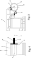
- the rotary tool 10 may be shaped like a circular blade 11 rotatable about an axis of rotation R, shown in Figure 4 .
- the rotary tool 10 is configured to be rotated about the axis of rotation R by an electro-spindle (not illustrated), which engages with a shank 13 of the rotary tool 10.
- the circular blade 11 may have a smooth cutting profile 12, that is to say, not serrated and without teeth.
- the circular blade 11 is made of a material for sharp tools, which are able to cut elastomeric materials.
- the circular blade 11 may be, for example, made of steel.
- the working unit 9 comprises a controller, not illustrated, for controlling the movement of the rotary tool 10.
- the controller is configured for activating or deactivating the rotary tool 10 and for setting operating parameters of the rotary tool 10.
- the controller is configured for moving the rotary tool 10 along a predetermined path in order to bring the rotary tool 10 to interact with the seal 6 and then move the rotary tool 10 away from the seal 6.
- the rotary tool 10 is controlled in such a way as to be moved along a path P indicated with a dot-dashed line.
- the rotary tool 10 is initially in a rest position P0, spaced from the profiled bar 3.
- the profiled bar 3 comprises two seals 6, that is to say, a first seal 6a and a second seal 6b arranged at different positions.
- the rotary tool 10 is moved to be carried to a first operating position P1, indicated schematically in Figure 2 , so as to interact with the first seal 6a applied on the profiled bar 3.
- the rotary tool 10 can be brought to the first working position P1 for example by moving the rotary tool 10 along a horizontal portion of path. At this point, the rotary tool 10 performs the necessary operation on the first seal 6a.
- the rotary tool 10 is then moved to a second working position P2, in order to interact with the second seal 6b. According to the example shown, the rotary tool 10 is moved from the first working position P1 to the second working position P2 along a rectilinear and inclined portion of path.
- Figure 2 shows only one example of how the rotary tool 10 can be moved.
- the number, the position and the geometry of the seals 6 may be different from that shown in Figure 2 , as well as the path P of the rotary tool 10 and the shape and dimensions of the cross-section of the profiled bar 3.
- the rotary tool 10 may be controlled in such a way as to optimise the path which the rotary tool 10 follows to perform the working operations requested on the seals 6 of the profiled bars 3, depending on the configuration of each profiled bar 3 and the respective seal(s) 6.
- the rotary tool 10 may be configured to perform working operations on the seals 6 without interacting with the material which forms the profiled bar 3. This allows the selection, for the rotary tool 10, of the material, shape and operating parameters which best adapt to the elastomeric material of the seals 6, irrespective of the material of the profiled bars 3.
- the rotary tool 10 is therefore a specific tool for the seals 6, that is to say, a tool dedicated to the seals 6, selected for performing on the seals 6 the required operations with a good degree of finishing, in particular leaving on the seals 6 good quality cut edges.
- the mechanical working operations required on the profiled bars 3 will, on the other hand, be carried out using specific tools, selected as a function of the material of the profiled bars 3 and the type of working operations to be performed.
- the rotary tool 10 is generally configured to perform cutting operations on the seals 6 for cutting at least a portion of the seal 6.
- the rotary tool 10 may be configured to act on a frayed edge of the seal 6, for example on an edge of the seal 6 which has been cut in an inappropriate manner during a previous working operation to which the profiled bar 3 has been subjected.
- This allows to remove from the seal 6 pieces of elastomeric material or portions of elastomeric material which are already partly detached, that could subsequently prove to be problematic.
- the portions of elastomeric material already partly detached might not be completely melted on the welding machine 7 and might therefore give rise to localised hardening or, more generally, imperfections on the welded joint resulting from the joining of two adjacent profiled bars 3.
- These imperfections, as well as reducing the quality of the welded joint might create drawbacks during subsequent operations to be performed on the frame, such as, for example, the fitting and the locking of a pane of glass.
- the frayed edges on the seal 6 might have been formed when cutting the extruded semi-finished product 5 to obtain the profiled bars 2, or during other working operations to which the profiled bar 3 has been subjected.
- the rotary tool 10 may be configured to act on an un-frayed edge of the seal 6, for example on an edge of the seal 6 which has been previously cut with a good quality of cut, or on a portion of the seal 6 which has not yet been subjected to cutting operations.
- the rotary tool 10 may be configured to cut portions of the seals 6 close to an end section 14 of the profiled bar 3 at which the profiled bar 3 must be welded to a further profiled bar 3. This operation is performed so as to minimise the elastomeric material of the seals 6 close to the end sections 14 of the profiled bars 3 to be joined.
- the elastomeric material which forms the seals 6 behaves differently from the material of the profiled bars 3 during welding.
- the elastomeric material of the seals 6 could crystallise during welding, in which case the crystallised elastomeric material would result in undesired hardening on the welded joint.
- Additional working operations may also be performed on the profiled bars 3, involving chip removal, as well as cutting operations for cutting the extruded semifinished product 5 which occurs in the cutting unit 4.
- milling operations may be performed on the profiled bars 3.
- the milling operations may optionally be performed to obtain, along an outer profile of an end section 14 of the profiled bar 3, a seat intended to house at least partly a welding bead formed when the profiled bar 3 is joined to a further profiled bar 3.
- the milling operations can also be called “contouring operations", since they are carried out along the contour of a cross-section of the profiled bar 3, that is to say, the end section 14.
- the tool device 15 has a first end 16 intended to be fixed to a spindle, in particular an electric spindle, of a machine tool.
- the tool device 15 has a body 17 which extends mainly along a longitudinal axis Z.
- a milling cutter 19 is provided for performing milling operations on the profiled bars 3.
- the tool device 15 also comprises a circular blade 111, identical to the circular blade 11 shown in Figures 2 to 4 , located in a position interposed between the first end 16 and the second end 18.
- the tool device 15 can be rotated about the longitudinal axis Z by the spindle of the machine tool on which it is mounted. By rotating the tool device 15 it is possible to simultaneously rotate both the cutter 19 and the circular blade 111.
- the tool device 15 is controlled by a controller, which may be associated with the machine tool on which the tool device 15 is mounted, so as to interact with a profiled bar 3 according to a desired path and with desired working parameters.
- the tool device 15 may be brought to interact with the profiled bar 3 according to two different working methods.
- a first working method shown in Figure 7
- the circular blade 111 is brought to interact with the seal 6 so as to cut portions of seal 6.
- the tool device 15 can be moved in such a way that the milling cutter 19 interacts with the end section 14 of the profiled bar 3 to make on it the seat 20 in which the welding bead can be received.
- the circular blade 111 cuts firstly the portions of seal 6 arranged close to the end section 14 on which the milling cutter 9 shall act. Subsequently, the milling cutter 9 performs the contouring operations on the end section 14, in such a way as to not be obstructed by the seals 6 and not to determine a poor quality cut of the seals 6.
- the tool device 15 allows both the contouring operations and the cutting of the seals 6 to be performed, with a single device and, therefore, quickly, which makes it possible to obtain a good quality welded joint.
- the tool device 15 could be positioned in the working unit 9.
- the working unit 9 could be integrated in the cutting unit 4, in which case both the cutting of the extruded semi-finished product 5 and the cutting of the seals 6 could be performed in a single operating unit, and also any milling operations such as, for example, the contouring operations on the end sections 14, if these operations (milling and, if necessary, contouring) are provided.
- the cutting unit 4, and, if necessary, the working unit 9 integrated in it or associated with it, may be located in a position different from the welding machine 7 and far from the welding machine 7, so that the cutting of the profiled bars 3 and, if necessary, the seals 6 can be made at different times with respect to the welding operations.
- the rotary tool 10 which comprises the circular blade 11, or the circular blade 111 of the tool device 15, it is possible to minimise or even avoid the defects which may form on the frame 2 due to the presence of the seal 6 close to the welded joint. This does not result in substantial productivity losses with respect to a traditional machine, since the cutting operations performed on the seal 6 are in any case performed automatically.
Landscapes
- Engineering & Computer Science (AREA)
- Mechanical Engineering (AREA)
- Civil Engineering (AREA)
- Structural Engineering (AREA)
- Life Sciences & Earth Sciences (AREA)
- Forests & Forestry (AREA)
- Milling Processes (AREA)
- Joining Of Corner Units Of Frames Or Wings (AREA)
Abstract
- preparing a profiled bar (3) made of a material containing a synthetic polymer, at least one seal (6) being applied on the profiled bar (3);
- joining the profiled bar (3) to at least a further profiled bar (3), by welding, to obtain a sealed joint of a door or window frame (2).
Description
- The invention relates to a method, a plant and a tool device to be used for processing profiled bars made of a material which contains at least a synthetic polymeric material, in particular, but not exclusively, for processing profiled bars made of polyvinyl chloride (PVC). More specifically, the invention is intended to be applied in the field of processing profiled bars for making doors or window frames.
- Plants are known for forming door or window frames from profiled bars made of synthetic polymeric material, for example PVC. The known plants comprise a welding machine, for example of the type disclosed in European patent application
EP 3517279 , for joining by welding a plurality of profiled bars at respective end portions, so as to form corner zones of the frame. - Upstream of the welding machine, other machines may be provided which are suitable for performing preliminary working operations on the profiled bars, the preliminary working operations being necessary for making the frame, in particular cutting and milling operations. The cutting operations make it possible to obtain, from a profiled bar having a significant length, a plurality of shorter profiled bars, having a length suitable for forming the door or window frame. The milling operations, on the other hand, may allow material to be removed in an end portion of the profiled bars cut previously, so as to make, along a perimeter zone of the end portion, a seat intended to receive a welding bead which will be originated on the welding machine, in such a way as to prevent the welding bead from protruding towards the outside of the corner zone of the frame, which would not be aesthetically attractive. These milling operations in an end portion of the profiled bar are also known as contouring operations.
- The above-mentioned cutting and milling operations may be performed in sequence in a single machining centre, or they may be performed at different times, respectively on cutting machines and contouring machines. Both the machining centre and the cutting machines and the contouring machines may be arranged in the same production line in which the welding machine is present or they may be arranged in a place different from that in which the welding machine is located.
- The profiled bars intended to form door or window frames may comprise one or more longitudinal seals, made, for example, of rubber, fixed on an outer surface of the profiled bars in predetermined positions. The longitudinal seals are intended to ensure that the door or window frame is able to close in an effective manner the door or window in which the frame will be installed.
- The mechanical working operations, for example cutting or milling operations, carried out on profiled bars having longitudinal seals, may result in several drawbacks, especially in the case of longitudinal seals having a cross-section of significant dimensions or made with a particularly soft elastomeric material.
- When a tool, for example a blade or a cutter intended to operate on the PVC with which the profiled bar is made, interacts with the seal, the latter may be torn. If this occurs, pieces of seal may remain attached to the profiled bar, which can cause imperfections during the subsequent welding of the profiled bars or may create difficulties while installing the frame, for example when a glass panel is mounted on the frame.
- Another drawback which may occur when profiled bars are welded on which seals are applied, even if the seals have been correctly cut and do not have portions partly detached, is linked to the fact that, during welding, the facing end zones of two profiled bars to be joined are locally melted or softened and pressed against each other. As a result, the profiled bars shorten by a few millimetres during the welding operations. When this occurs, the material of the seals, which behaves differently from the PVC or other polymeric material with which the profiled bars are formed, gives rise to an excess of material which may crystallize during heating. This excess material may be annoying during the subsequent operations to which the frame has to be subjected, for example when a glass panel has to be applied on the frame, or when a door or a window shutter made starting from the frame has to be closed.
- Prior art documents
EP0978339 ,WO2021/024111 ,EP0900907 ,EP3090858 ,DE202015101493 disclose some examples of apparatuses for processing profiled bars. - An object of the invention is to improve the methods, the plants and the tools for processing profiled bars made of a material which comprises at least one synthetic polymer, for example profiled bars made of PVC. Another object is to increase the quality of the door and window frames made from profiled bars made of a material which comprises at least one synthetic polymer, for example profiled bars made of PVC, on which seals are applied.
- A further object is to provide bars made of a material which comprises at least one synthetic polymer, for example PVC, in which no pieces of seals having significant dimensions remain attached to the profiled bar after cutting or milling operations are performed on the latter.
- Another object is to provide profiled bars intended to be joined by welding to form door and window frames, in which the profiled bars are provided with seals and in which, even after welding, there is no build-up of material forming the seals.
- In a first aspect of the invention, there is provided a method comprising the steps of:
- preparing a profiled bar made of a material containing a synthetic polymer, at least one seal being applied on the profiled bar;
- joining the profiled bar to at least a further profiled bar, by welding, to obtain a sealed joint of a door or window frame;
- Owing to this aspect of the invention, it is possible to selectively remove portions of seal with a dedicated tool, that is to say, with a tool specifically designed for acting on the material of the seal, so as to cut that material without leaving shreds or frayed parts. The material of the seal is usually an elastomeric material. Any operations, for example milling, to be performed on the profiled bar, that is to say, on the material containing at least one synthetic polymer, will be performed with a different tool, which shall not interact with the seal.
- This avoids cutting of the seal with the same tool which processes the profiled bar, which would generate defective cut edges on the seal. This makes it possible to limit the defects which could arise during subsequent processing steps, due to the seal being cut incorrectly.
- The step of cutting at least a part of the seal by the dedicated rotary tool may be performed after the seal has already been cut to the desired length to form the door or window frame.
- In an embodiment, the dedicated rotary tool comprises a circular blade having a smooth cutting profile.
- This allows the seal to be effectively cut, minimising or eliminating the defects linked to the cut.
- In an embodiment, the dedicated rotary tool is used to remove a part of the seal applied to a region of the profiled bar in which a working operation will be subsequently performed, said working operation resulting in removal of the material containing a synthetic polymer with which the profiled bar is made.
- This ensures that, in the zone in which a further tool specifically intended for removing the material of the profiled bar will work, no large portions of seal are present. Consequently, the interactions between the seal and the further tool which acts on the profiled bar are avoided, or at least minimised. These interactions are undesired since they could be responsible for edges of the seal cut in a defective manner.
- In an embodiment, the dedicated rotary tool is used to remove a part of the seal applied to a region of the profiled bar in which a working operation has been performed, said working operation resulting in removal of the material containing a synthetic polymer with which the profiled bar is made.
- This makes it possible to restore a good quality to a cut edge of the seal at the regions of the seal which have previously interacted with a tool which has performed the working operation on the profiled bar.
- In both cases, the working operation which results in the chip removal may be a milling operation.
- In an embodiment, the working operation which results in chip removal may be a contouring operation for forming, along an outer profile of an end section of the profiled bar, a seat intended to at least partly house a welding bead formed when the profiled bar is joined to the further profiled bar.
- In an embodiment, the dedicated rotary tool is used to remove a part of the seal applied close to an end section of the profiled bar intended to be joined to the further profiled bar.
- This prevents the end section of the profiled bar intended to be joined to the further profiled bar from having parts of seals with significant dimensions, which could result in an accumulation of material of the seal close to a welded joint which joins the two profiled bars. The accumulation of material of the seal is undesired since it could adversely affect the quality of the welded joint or make it more difficult to carry out subsequent operations.
- In an embodiment, there is provided the step of moving the dedicated tool along a predetermined path to bring the dedicated tool to interact with the seal.
- It is thus possible to decide in which manner the dedicated tool has to move towards the seal, how the cut has to be performed, on which side the seal has to be cut, and determine other working conditions, which makes the method according to the first aspect of the invention particularly flexible.
- In a second aspect of the invention, there is provided a plant for forming door or window frames starting from profiled bars made with a material containing a synthetic polymer, the plant comprising a cutting unit for cutting a profiled bar to a desired length, a welding machine for joining a profiled bar to at least a further profiled bar by welding, the plant further comprising a tool device which includes a rotary tool for cutting at least a portion of a seal applied on the profiled bar.
- In an embodiment, the rotary tool comprises a circular blade having a smooth cutting profile.
- In an embodiment, the rotary tool may be configured to act on the seal without interacting with the material containing a synthetic polymer which forms the profiled bar.
- Owing to the second aspect of the invention, it is possible to act on the seal, where portions are to be removed, with a dedicated tool, designed specifically for interacting with the material which forms the seal. The working operations, which may be milling or other, to be performed on the profiled bar, will be carried out with a further tool, specific for the material containing a synthetic polymer which forms the profiled bar.
- In a third aspect of the invention, a tool device is provided for processing a profiled bar made of a material containing a synthetic polymer, the tool device comprising a first end intended to be fixed to a spindle of a machine tool, a milling cutter being arranged at a second end of the tool device for performing a milling operation on the profiled bar, the second end being opposite the first end, in which the tool device further comprises a rotatable circular blade interposed between the first end and the milling cutter for cutting a seal made of elastomeric material applied on the profiled bar.
- The tool device according to the third aspect of the invention may be used successfully for processing profiled bars on which seals are applied.
- In particular, the rotatable circular blade may be used for cutting portions of seals in zones in which subsequent operations have to be performed, for example working operations with removal of material to be performed by the milling cutter, or welding operations.
- This makes it possible to obtain cut edges with a good quality in the seal and - if necessary - prevent accumulation of material of the seal at the zones to be welded.
- The invention can be better understood and implemented with reference to the accompanying drawings which illustrate non-limiting example embodiments of it and in which:
-
Figure 1 is a schematic plan view of a plant for processing profiled bars to obtain door or window frames; -
Figure 2 shows a cross section of a profiled bar and a rotary tool for cutting portions of seal applied on the profiled bar; -
Figure 3 shows, in an enlarged scale, a cross-section of the profiled bar of -
Figure 2 , together with the rotary tool which is cutting the seal; -
Figure 4 is a schematic side view from the left ofFigure 3 ; -
Figure 5 is a perspective view showing a tool device; -
Figure 6 is a side view of the tool device ofFigure 5 ; -
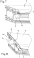
Figure 7 shows the tool device ofFigure 5 , whilst a rotary blade of the device is cutting a seal: -
Figure 8 shows the tool device ofFigure 5 , whilst a milling cutter of the device is processing a profiled bar. -
Figure 1 schematically shows aplant 1 for forming door orwindow frames 2 starting from profiledbars 3 made of a material containing a synthetic polymer. - The profiled bars 3 may be made entirely of a synthetic polymeric material, or they may comprise a synthetic polymeric material and another material, for example in the case of profiled bars made of composite material.
- In general, the profiled
bars 3 may be made of any heat-weldable material. One ormore seals 6 may be applied on the profiledbars 3, each of which normally extends in a longitudinal direction, that is to say, parallel to the length of the profiled bars 3. Theseals 6 may be made with an elastomeric material. Theseals 6 are used to ensure that the doors and windows of which theframes 2 form part close without allowing draughts and currents of air to pass. - The
seals 6 are fixed to the profiledbars 3, for example by gluing or because they have been formed directly in contact with the profiledbars 3, for example by coextrusion. - The
plant 1 comprises acutting unit 4, which receives at its inlet an extrudedsemi-finished product 5, on which there are already one ormore seals 6, having a length greater than the length of the profiledbars 3 which are used to form theframe 2. Thecutting unit 4 is configured for cutting the extrudedsemi-finished product 5 so as to obtain from it profiled bars 3 of the desired length. - The
plant 1 further comprises awelding machine 7, arranged to join together by heat-welding a plurality of profiledbars 3, for example four profiledbars 3, in such a way as to form aframe 4. For this purpose, thewelding machine 7 may comprise fourwelding heads 8, each of which is arranged to join together two profiledbars 3 at a corner zone of theframe 4. Thewelding machine 7 will not be described in detail here, because it is of known type. For example, thewelding machine 7 may be of the type disclosed in European patent applicationEP 3517279 . - The
plant 1 may further comprise a workingunit 9 comprising a workingdevice 21 for performing additional working operations on the profiledbars 3, after the latter have been cut to the desired length and before they are welded to each other. The workingdevice 21 may be, for example, configured to perform an operation which results in chip removal on the profiled bars 3. For example, the workingdevice 21 could be configured to perform, on an end section of each profiledbar 3, a perimeter milling operation aimed at forming, along the profile of the end section, a seat suitable for receiving a welding bead which is generated when two profiledbars 3 are joined on thewelding machine 7. - In the example shown, the working
unit 9 is interposed between the cuttingunit 4 and thewelding machine 7, but this condition is not necessary. - The working
device 21 is configured to perform working operations at least on theseals 6 applied to the profiledbars 3, in particular by removing portions of theseals 6 in positions in which the material of theseals 6 could give rise to subsequent drawbacks. - The working
device 21 may comprise arotary tool 10 of the type shown inFigures 2 to 4 . Therotary tool 10 may be shaped like acircular blade 11 rotatable about an axis of rotation R, shown inFigure 4 . Therotary tool 10 is configured to be rotated about the axis of rotation R by an electro-spindle (not illustrated), which engages with ashank 13 of therotary tool 10. - The
circular blade 11 may have asmooth cutting profile 12, that is to say, not serrated and without teeth. - The
circular blade 11 is made of a material for sharp tools, which are able to cut elastomeric materials. Thecircular blade 11 may be, for example, made of steel. - The working
unit 9 comprises a controller, not illustrated, for controlling the movement of therotary tool 10. The controller is configured for activating or deactivating therotary tool 10 and for setting operating parameters of therotary tool 10. Moreover, the controller is configured for moving therotary tool 10 along a predetermined path in order to bring therotary tool 10 to interact with theseal 6 and then move therotary tool 10 away from theseal 6. - For example, in the case of
Figure 2 , therotary tool 10 is controlled in such a way as to be moved along a path P indicated with a dot-dashed line. Therotary tool 10 is initially in a rest position P0, spaced from the profiledbar 3. - According to this example, the profiled
bar 3 comprises twoseals 6, that is to say, afirst seal 6a and asecond seal 6b arranged at different positions. - The
rotary tool 10 is moved to be carried to a first operating position P1, indicated schematically inFigure 2 , so as to interact with thefirst seal 6a applied on the profiledbar 3. Therotary tool 10 can be brought to the first working position P1 for example by moving therotary tool 10 along a horizontal portion of path. At this point, therotary tool 10 performs the necessary operation on thefirst seal 6a. Therotary tool 10 is then moved to a second working position P2, in order to interact with thesecond seal 6b. According to the example shown, therotary tool 10 is moved from the first working position P1 to the second working position P2 along a rectilinear and inclined portion of path. -
Figure 2 shows only one example of how therotary tool 10 can be moved. In general, the number, the position and the geometry of theseals 6 may be different from that shown inFigure 2 , as well as the path P of therotary tool 10 and the shape and dimensions of the cross-section of the profiledbar 3. - The
rotary tool 10 may be controlled in such a way as to optimise the path which therotary tool 10 follows to perform the working operations requested on theseals 6 of the profiledbars 3, depending on the configuration of each profiledbar 3 and the respective seal(s) 6. - The
rotary tool 10 may be configured to perform working operations on theseals 6 without interacting with the material which forms the profiledbar 3. This allows the selection, for therotary tool 10, of the material, shape and operating parameters which best adapt to the elastomeric material of theseals 6, irrespective of the material of the profiled bars 3. - The
rotary tool 10 is therefore a specific tool for theseals 6, that is to say, a tool dedicated to theseals 6, selected for performing on theseals 6 the required operations with a good degree of finishing, in particular leaving on theseals 6 good quality cut edges. - The mechanical working operations required on the profiled
bars 3 will, on the other hand, be carried out using specific tools, selected as a function of the material of the profiledbars 3 and the type of working operations to be performed. - The
rotary tool 10 is generally configured to perform cutting operations on theseals 6 for cutting at least a portion of theseal 6. - In a first embodiment, the
rotary tool 10 may be configured to act on a frayed edge of theseal 6, for example on an edge of theseal 6 which has been cut in an inappropriate manner during a previous working operation to which the profiledbar 3 has been subjected. This allows to remove from theseal 6 pieces of elastomeric material or portions of elastomeric material which are already partly detached, that could subsequently prove to be problematic. For example, the portions of elastomeric material already partly detached might not be completely melted on thewelding machine 7 and might therefore give rise to localised hardening or, more generally, imperfections on the welded joint resulting from the joining of two adjacent profiled bars 3. These imperfections, as well as reducing the quality of the welded joint, might create drawbacks during subsequent operations to be performed on the frame, such as, for example, the fitting and the locking of a pane of glass. - The frayed edges on the
seal 6 might have been formed when cutting the extrudedsemi-finished product 5 to obtain the profiledbars 2, or during other working operations to which the profiledbar 3 has been subjected. - In an alternative embodiment, the
rotary tool 10 may be configured to act on an un-frayed edge of theseal 6, for example on an edge of theseal 6 which has been previously cut with a good quality of cut, or on a portion of theseal 6 which has not yet been subjected to cutting operations. - In particular, the
rotary tool 10 may be configured to cut portions of theseals 6 close to anend section 14 of the profiledbar 3 at which the profiledbar 3 must be welded to a further profiledbar 3. This operation is performed so as to minimise the elastomeric material of theseals 6 close to theend sections 14 of the profiledbars 3 to be joined. In effect, the elastomeric material which forms theseals 6 behaves differently from the material of the profiledbars 3 during welding. In particular, the elastomeric material of theseals 6 could crystallise during welding, in which case the crystallised elastomeric material would result in undesired hardening on the welded joint. - Additional working operations may also be performed on the profiled
bars 3, involving chip removal, as well as cutting operations for cutting the extrudedsemifinished product 5 which occurs in thecutting unit 4. - For example, in an embodiment, milling operations may be performed on the profiled bars 3.
- The milling operations may optionally be performed to obtain, along an outer profile of an
end section 14 of the profiledbar 3, a seat intended to house at least partly a welding bead formed when the profiledbar 3 is joined to a further profiledbar 3. In this case, the milling operations can also be called "contouring operations", since they are carried out along the contour of a cross-section of the profiledbar 3, that is to say, theend section 14. - In order to prevent that, at the end of the contouring operations, a frayed edge remains on the
seals 6, it is possible to cut portions ofseals 6 using a dedicated tool, near the regions in which the milling operations must be performed, in particular near theend section 14. - In this case, it is possible to use a
single tool device 15, of the type shown inFigures 5 and 6 . - The
tool device 15 has afirst end 16 intended to be fixed to a spindle, in particular an electric spindle, of a machine tool. Thetool device 15 has abody 17 which extends mainly along a longitudinal axis Z. At asecond end 18 of thebody 17, opposite to thefirst end 16, amilling cutter 19 is provided for performing milling operations on the profiled bars 3. - The
tool device 15 also comprises acircular blade 111, identical to thecircular blade 11 shown inFigures 2 to 4 , located in a position interposed between thefirst end 16 and thesecond end 18. - The
tool device 15 can be rotated about the longitudinal axis Z by the spindle of the machine tool on which it is mounted. By rotating thetool device 15 it is possible to simultaneously rotate both thecutter 19 and thecircular blade 111. - The
tool device 15 is controlled by a controller, which may be associated with the machine tool on which thetool device 15 is mounted, so as to interact with a profiledbar 3 according to a desired path and with desired working parameters. - The
tool device 15 may be brought to interact with the profiledbar 3 according to two different working methods. According to a first working method, shown inFigure 7 , thecircular blade 111 is brought to interact with theseal 6 so as to cut portions ofseal 6. - According to a second working method, shown in
Figure 8 , thetool device 15 can be moved in such a way that themilling cutter 19 interacts with theend section 14 of the profiledbar 3 to make on it theseat 20 in which the welding bead can be received. - According to the example shown, the
circular blade 111 cuts firstly the portions ofseal 6 arranged close to theend section 14 on which themilling cutter 9 shall act. Subsequently, themilling cutter 9 performs the contouring operations on theend section 14, in such a way as to not be obstructed by theseals 6 and not to determine a poor quality cut of theseals 6. - It is also possible to reverse this working operations order, if desired.
- The
tool device 15 allows both the contouring operations and the cutting of theseals 6 to be performed, with a single device and, therefore, quickly, which makes it possible to obtain a good quality welded joint. - The
tool device 15 could be positioned in the workingunit 9. - It is also possible to adopt a layout different from that described above and shown in
Figure 1 . - For example, the working
unit 9 could be integrated in thecutting unit 4, in which case both the cutting of the extrudedsemi-finished product 5 and the cutting of theseals 6 could be performed in a single operating unit, and also any milling operations such as, for example, the contouring operations on theend sections 14, if these operations (milling and, if necessary, contouring) are provided. - The
cutting unit 4, and, if necessary, the workingunit 9 integrated in it or associated with it, may be located in a position different from thewelding machine 7 and far from thewelding machine 7, so that the cutting of the profiledbars 3 and, if necessary, theseals 6 can be made at different times with respect to the welding operations. - Whatever the layout selected, using a dedicated rotary tool, that is to say, the
rotary tool 10 which comprises thecircular blade 11, or thecircular blade 111 of thetool device 15, it is possible to minimise or even avoid the defects which may form on theframe 2 due to the presence of theseal 6 close to the welded joint. This does not result in substantial productivity losses with respect to a traditional machine, since the cutting operations performed on theseal 6 are in any case performed automatically.
Claims (11)
- A method comprising the steps of:- preparing a profiled bar (3) made of a material containing a synthetic polymer, at least one seal (6) being applied on the profiled bar (3);- joining the profiled bar (3) to at least a further profiled bar (3), by welding, to obtain a sealed joint of a door or window frame (2);wherein, before the joining step, there is provided a step of cutting at least a part of the seal (6), the cutting step being performed with a dedicated rotary tool (10; 111) specifically arranged to act on the seal (6), wherein the dedicated rotary tool (10; 111) comprises a circular blade (11; 111) having a smooth cutting profile.
- The method according to claim 1, wherein the dedicated rotary tool (10; 111) is used to cut a part of the seal (6) applied to a region of the profiled bar (3) in which a working operation will be subsequently performed, said working operation resulting in removal of the material containing a synthetic polymer with which the profiled bar (3) is made.
- The method according to claim 1, wherein the dedicated rotary tool (10; 111) is used to cut a part of the seal (6) applied to a region of the profiled bar (3) in which a working operation has been performed, said working operation resulting in removal of the material containing a synthetic polymer with which the profiled bar (3) is made.
- The method according to claim 2 or 3, wherein the working operation which results in chip removal is a milling operation.
- The method according to any one of claims 2 to 4, wherein the working operation which results in chip removal is a contouring operation for forming, along an outer profile of an end section (14) of the profiled bar (3), a seat (20) intended to at least partly house a welding bead formed when the profiled bar (3) is joined to the further profiled bar (3).
- The method according to claim 1, wherein the dedicated rotary tool (10; 111) is used to cut a part of the seal (6) applied close to an end section (14) of the profiled bar (3) intended to be joined to the further profiled bar (3).
- The method according to any preceding claim, wherein the dedicated rotary tool (10; 111) is moved along a predetermined path in order to be brought to interact with the seal (6).
- The method according to any preceding claim, wherein the dedicated rotary tool (10; 111) is integrated in a tool device (15) comprising a body (17) having a first end (16) and a second end (18) opposite the first end (16), the first end (16) being intended to be fixed to a spindle (20) of a machine tool, a milling cutter (19) being arranged at the second end (18) for performing a milling operation on the profiled bar (3), the dedicated rotary tool (111) being interposed between the milling cutter (19) and the first end (16).
- A plant for forming door or window frames (2) starting from profiled bars (3) made with a material containing a synthetic polymer, the plant (1) comprising a cutting unit (4) for cutting a profiled bar (3) to a desired length, a welding machine (7) for joining a profiled bar (3) to at least a further profiled bar (3) by welding, the plant (1) further comprising a work device (21) which includes a rotary tool (10; 111) for cutting at least a portion of a seal (6) applied on the profiled bar (3), wherein the rotary tool (10; 111) comprises a circular blade (11; 111) having a smooth cutting profile.
- The plant according to claim 9, wherein the rotary tool (10; 111) is integrated in a tool device (15) comprising a body (17) having a first end (16) and a second end (18) opposite the first end (16), the first end (16) being intended to be fixed to a spindle (20) of a machine tool, a milling cutter (19) being arranged at the second end (18) for performing a milling operation on the profiled bar (3), the dedicated rotary tool (111) being interposed between the milling cutter (19) and the first end (16).
- A tool device for processing a profiled bar (3) made of a material containing a synthetic polymer, the tool device (15) comprising a first end (16) intended to be fixed to a spindle of a machine tool, a milling cutter (19) being arranged at a second end (18) of the tool device (15) for performing a milling operation on the profiled bar (3), the second end (18) being opposite the first end (16), wherein the tool device (15) further comprises a rotatable circular blade (111) interposed between the first end (16) and the milling cutter (19) for cutting a seal (6) made of elastomeric material applied on the profiled bar (3).
Applications Claiming Priority (1)
| Application Number | Priority Date | Filing Date | Title |
|---|---|---|---|
| IT102022000007391A IT202200007391A1 (en) | 2022-04-13 | 2022-04-13 | Method, system and tool device for processing profiled bars. |
Publications (2)
| Publication Number | Publication Date |
|---|---|
| EP4261019A1 true EP4261019A1 (en) | 2023-10-18 |
| EP4261019B1 EP4261019B1 (en) | 2026-03-04 |
Family
ID=82385535
Family Applications (1)
| Application Number | Title | Priority Date | Filing Date |
|---|---|---|---|
| EP23167559.6A Active EP4261019B1 (en) | 2022-04-13 | 2023-04-12 | Method, plant and tool device for processing profiled bars |
Country Status (2)
| Country | Link |
|---|---|
| EP (1) | EP4261019B1 (en) |
| IT (1) | IT202200007391A1 (en) |
Citations (6)
| Publication number | Priority date | Publication date | Assignee | Title |
|---|---|---|---|---|
| EP0900907A2 (en) | 1997-09-08 | 1999-03-10 | RAPID MASCHINENBAU GmbH | Machining process for hollow section members to be welded including rubber seals |
| EP0978339A2 (en) | 1998-08-04 | 2000-02-09 | Bernhard Eisenbach | Milling device for recesses on window profiles |
| DE202015101493U1 (en) | 2015-03-24 | 2016-06-28 | Urban Gmbh & Co Maschinenbau Kg | milling cutter |
| EP3090858A2 (en) | 2015-04-13 | 2016-11-09 | Taicang Wegoma Machinery Co., Ltd. | Welding method free of bead trimming and double-head cutting saw with automatic processing function |
| EP3517279A1 (en) | 2018-01-30 | 2019-07-31 | Emmegi S.P.A. | An apparatus for welding profiled bars |
| WO2021024111A1 (en) | 2019-08-05 | 2021-02-11 | Graf Synergy S.R.L. | Profiled element for doors/windows made of plastic material, in particular pvc |
-
2022
- 2022-04-13 IT IT102022000007391A patent/IT202200007391A1/en unknown
-
2023
- 2023-04-12 EP EP23167559.6A patent/EP4261019B1/en active Active
Patent Citations (6)
| Publication number | Priority date | Publication date | Assignee | Title |
|---|---|---|---|---|
| EP0900907A2 (en) | 1997-09-08 | 1999-03-10 | RAPID MASCHINENBAU GmbH | Machining process for hollow section members to be welded including rubber seals |
| EP0978339A2 (en) | 1998-08-04 | 2000-02-09 | Bernhard Eisenbach | Milling device for recesses on window profiles |
| DE202015101493U1 (en) | 2015-03-24 | 2016-06-28 | Urban Gmbh & Co Maschinenbau Kg | milling cutter |
| EP3090858A2 (en) | 2015-04-13 | 2016-11-09 | Taicang Wegoma Machinery Co., Ltd. | Welding method free of bead trimming and double-head cutting saw with automatic processing function |
| EP3517279A1 (en) | 2018-01-30 | 2019-07-31 | Emmegi S.P.A. | An apparatus for welding profiled bars |
| WO2021024111A1 (en) | 2019-08-05 | 2021-02-11 | Graf Synergy S.R.L. | Profiled element for doors/windows made of plastic material, in particular pvc |
Also Published As
| Publication number | Publication date |
|---|---|
| IT202200007391A1 (en) | 2023-10-13 |
| EP4261019B1 (en) | 2026-03-04 |
Similar Documents
| Publication | Publication Date | Title |
|---|---|---|
| EP2366479B1 (en) | A plant and a method for manufacturing frames of doors or windows | |
| KR101718330B1 (en) | Method and device for machining the tooth edges of end-cut work wheels | |
| EP3090858B1 (en) | Double-head cutting saw with automatic processing function | |
| KR102209578B1 (en) | Device for multi-angle cutting material of window frame | |
| US11629547B2 (en) | Device and method for connecting profiled parts | |
| CN105050797A (en) | Method for welding profile parts made of PVC or other plastics | |
| US6006408A (en) | Vinyl window frame weld seam cleaner | |
| EP4261019B1 (en) | Method, plant and tool device for processing profiled bars | |
| EP3072668B2 (en) | Method and device for connecting profile sections | |
| US5370835A (en) | Method of manufacturing rectangular frames | |
| CN109476093B (en) | Machine for sealing plastic shaped elements | |
| EP3248745B1 (en) | Edge-banding machine provided with a milling device and operation method of said edge-banding machine | |
| WO2021071385A1 (en) | Welding head device and method for manufacturing plastic windows | |
| GB2376656A (en) | Removing notches from the weld face areas of components, to locally reduce waste sprue produced during thermal bonding, apparatus, method & preparation | |
| US20100154934A1 (en) | Apparatus and methods for shaping and machining elongate workpieces | |
| EP2361738A1 (en) | Operating unit for a machining centre | |
| EP0909602B1 (en) | Cleaning device for window or door frames | |
| JP2023016751A5 (en) | ||
| JP2009527367A (en) | Shaper | |
| EP0460792B1 (en) | Metal reinforcements for sealing strips and the like and methods of making them | |
| US20050141974A1 (en) | Trimming device | |
| KR20090124085A (en) | Clamping Device for Chamfering Machine | |
| JP2020514092A (en) | Device for processing rod-shaped workpieces, for example window profiles or door profiles | |
| WO2008075937A1 (en) | Machine tool | |
| EP1430996B1 (en) | Machining unit for deburring corner joints of frames of welded plastic profiles |
Legal Events
| Date | Code | Title | Description |
|---|---|---|---|
| PUAI | Public reference made under article 153(3) epc to a published international application that has entered the european phase |
Free format text: ORIGINAL CODE: 0009012 |
|
| STAA | Information on the status of an ep patent application or granted ep patent |
Free format text: STATUS: THE APPLICATION HAS BEEN PUBLISHED |
|
| AK | Designated contracting states |
Kind code of ref document: A1 Designated state(s): AL AT BE BG CH CY CZ DE DK EE ES FI FR GB GR HR HU IE IS IT LI LT LU LV MC ME MK MT NL NO PL PT RO RS SE SI SK SM TR |
|
| STAA | Information on the status of an ep patent application or granted ep patent |
Free format text: STATUS: REQUEST FOR EXAMINATION WAS MADE |
|
| 17P | Request for examination filed |
Effective date: 20240328 |
|
| RBV | Designated contracting states (corrected) |
Designated state(s): AL AT BE BG CH CY CZ DE DK EE ES FI FR GB GR HR HU IE IS IT LI LT LU LV MC ME MK MT NL NO PL PT RO RS SE SI SK SM TR |
|
| P01 | Opt-out of the competence of the unified patent court (upc) registered |
Free format text: CASE NUMBER: APP_44441/2024 Effective date: 20240731 |
|
| GRAP | Despatch of communication of intention to grant a patent |
Free format text: ORIGINAL CODE: EPIDOSNIGR1 |
|
| STAA | Information on the status of an ep patent application or granted ep patent |
Free format text: STATUS: GRANT OF PATENT IS INTENDED |
|
| RIC1 | Information provided on ipc code assigned before grant |
Ipc: B29C 65/20 20060101AFI20251007BHEP Ipc: B29C 65/78 20060101ALI20251007BHEP Ipc: B23C 3/12 20060101ALI20251007BHEP Ipc: B26D 1/00 20060101ALI20251007BHEP Ipc: E06B 3/22 20060101ALI20251007BHEP Ipc: E06B 3/62 20060101ALN20251007BHEP |
|
| RIC1 | Information provided on ipc code assigned before grant |
Ipc: B29C 65/20 20060101AFI20251020BHEP Ipc: B29C 65/78 20060101ALI20251020BHEP Ipc: B23C 3/12 20060101ALI20251020BHEP Ipc: B26D 1/00 20060101ALI20251020BHEP Ipc: E06B 3/22 20060101ALI20251020BHEP Ipc: E06B 3/62 20060101ALN20251020BHEP |
|
| INTG | Intention to grant announced |
Effective date: 20251110 |
|
| GRAS | Grant fee paid |
Free format text: ORIGINAL CODE: EPIDOSNIGR3 |
|
| GRAA | (expected) grant |
Free format text: ORIGINAL CODE: 0009210 |
|
| STAA | Information on the status of an ep patent application or granted ep patent |
Free format text: STATUS: THE PATENT HAS BEEN GRANTED |
|
| AK | Designated contracting states |
Kind code of ref document: B1 Designated state(s): AL AT BE BG CH CY CZ DE DK EE ES FI FR GB GR HR HU IE IS IT LI LT LU LV MC ME MK MT NL NO PL PT RO RS SE SI SK SM TR |
|
| REG | Reference to a national code |
Ref country code: CH Ref legal event code: F10 Free format text: ST27 STATUS EVENT CODE: U-0-0-F10-F00 (AS PROVIDED BY THE NATIONAL OFFICE) Effective date: 20260304 Ref country code: GB Ref legal event code: FG4D |
|
| REG | Reference to a national code |
Ref country code: IE Ref legal event code: FG4D |
|
| REG | Reference to a national code |
Ref country code: DE Ref legal event code: R096 Ref document number: 602023012838 Country of ref document: DE |