EP4261006A1 - Stretching and cooling rod for forming containers - Google Patents
Stretching and cooling rod for forming containers Download PDFInfo
- Publication number
- EP4261006A1 EP4261006A1 EP23159164.5A EP23159164A EP4261006A1 EP 4261006 A1 EP4261006 A1 EP 4261006A1 EP 23159164 A EP23159164 A EP 23159164A EP 4261006 A1 EP4261006 A1 EP 4261006A1
- Authority
- EP
- European Patent Office
- Prior art keywords
- rod
- preform
- drawing rod
- container
- orifices
- Prior art date
- Legal status (The legal status is an assumption and is not a legal conclusion. Google has not performed a legal analysis and makes no representation as to the accuracy of the status listed.)
- Pending
Links
- 238000001816 cooling Methods 0.000 title claims description 35
- 239000000112 cooling gas Substances 0.000 claims abstract description 27
- 238000000465 moulding Methods 0.000 claims abstract description 26
- 238000004519 manufacturing process Methods 0.000 claims abstract description 16
- 238000000071 blow moulding Methods 0.000 claims abstract description 8
- 239000012530 fluid Substances 0.000 claims abstract description 8
- 238000004891 communication Methods 0.000 claims abstract description 6
- 238000007664 blowing Methods 0.000 claims description 40
- 238000002347 injection Methods 0.000 claims description 11
- 239000007924 injection Substances 0.000 claims description 11
- 238000000605 extraction Methods 0.000 claims description 2
- 238000000034 method Methods 0.000 abstract description 6
- 239000000463 material Substances 0.000 description 10
- 238000009434 installation Methods 0.000 description 9
- 229920000139 polyethylene terephthalate Polymers 0.000 description 8
- 239000005020 polyethylene terephthalate Substances 0.000 description 8
- 238000003780 insertion Methods 0.000 description 5
- 230000037431 insertion Effects 0.000 description 5
- 230000008569 process Effects 0.000 description 4
- 208000031968 Cadaver Diseases 0.000 description 3
- 230000007547 defect Effects 0.000 description 3
- 239000007789 gas Substances 0.000 description 3
- 230000008901 benefit Effects 0.000 description 2
- 230000007423 decrease Effects 0.000 description 2
- 238000013461 design Methods 0.000 description 2
- 239000012815 thermoplastic material Substances 0.000 description 2
- 238000010521 absorption reaction Methods 0.000 description 1
- 230000009471 action Effects 0.000 description 1
- 230000015572 biosynthetic process Effects 0.000 description 1
- 238000005352 clarification Methods 0.000 description 1
- 239000012141 concentrate Substances 0.000 description 1
- 238000009792 diffusion process Methods 0.000 description 1
- 230000000694 effects Effects 0.000 description 1
- 229940082150 encore Drugs 0.000 description 1
- 235000021183 entrée Nutrition 0.000 description 1
- 230000007613 environmental effect Effects 0.000 description 1
- 230000009477 glass transition Effects 0.000 description 1
- 238000012986 modification Methods 0.000 description 1
- 230000004048 modification Effects 0.000 description 1
- -1 polyethylene terephthalate Polymers 0.000 description 1
- 238000007665 sagging Methods 0.000 description 1
- 239000000243 solution Substances 0.000 description 1
- 238000012546 transfer Methods 0.000 description 1
Images


Classifications
-
- B—PERFORMING OPERATIONS; TRANSPORTING
- B29—WORKING OF PLASTICS; WORKING OF SUBSTANCES IN A PLASTIC STATE IN GENERAL
- B29C—SHAPING OR JOINING OF PLASTICS; SHAPING OF MATERIAL IN A PLASTIC STATE, NOT OTHERWISE PROVIDED FOR; AFTER-TREATMENT OF THE SHAPED PRODUCTS, e.g. REPAIRING
- B29C49/00—Blow-moulding, i.e. blowing a preform or parison to a desired shape within a mould; Apparatus therefor
- B29C49/08—Biaxial stretching during blow-moulding
- B29C49/10—Biaxial stretching during blow-moulding using mechanical means for prestretching
- B29C49/12—Stretching rods
- B29C49/121—Stretching rod configuration, e.g. geometry; Stretching rod material
- B29C49/1212—Stretching rod configuration, e.g. geometry; Stretching rod material the stretching rod comprising at least one opening on the surface, e.g. through which compressed air is blown into the preform to expand the same
-
- B—PERFORMING OPERATIONS; TRANSPORTING
- B29—WORKING OF PLASTICS; WORKING OF SUBSTANCES IN A PLASTIC STATE IN GENERAL
- B29C—SHAPING OR JOINING OF PLASTICS; SHAPING OF MATERIAL IN A PLASTIC STATE, NOT OTHERWISE PROVIDED FOR; AFTER-TREATMENT OF THE SHAPED PRODUCTS, e.g. REPAIRING
- B29C49/00—Blow-moulding, i.e. blowing a preform or parison to a desired shape within a mould; Apparatus therefor
- B29C49/08—Biaxial stretching during blow-moulding
- B29C49/10—Biaxial stretching during blow-moulding using mechanical means for prestretching
- B29C49/12—Stretching rods
- B29C49/121—Stretching rod configuration, e.g. geometry; Stretching rod material
- B29C49/1215—Geometry of the stretching rod, e.g. specific stretching rod end shape
-
- B—PERFORMING OPERATIONS; TRANSPORTING
- B29—WORKING OF PLASTICS; WORKING OF SUBSTANCES IN A PLASTIC STATE IN GENERAL
- B29C—SHAPING OR JOINING OF PLASTICS; SHAPING OF MATERIAL IN A PLASTIC STATE, NOT OTHERWISE PROVIDED FOR; AFTER-TREATMENT OF THE SHAPED PRODUCTS, e.g. REPAIRING
- B29C49/00—Blow-moulding, i.e. blowing a preform or parison to a desired shape within a mould; Apparatus therefor
- B29C49/42—Component parts, details or accessories; Auxiliary operations
- B29C49/64—Heating or cooling preforms, parisons or blown articles
- B29C49/66—Cooling by refrigerant introduced into the blown article
-
- B—PERFORMING OPERATIONS; TRANSPORTING
- B29—WORKING OF PLASTICS; WORKING OF SUBSTANCES IN A PLASTIC STATE IN GENERAL
- B29C—SHAPING OR JOINING OF PLASTICS; SHAPING OF MATERIAL IN A PLASTIC STATE, NOT OTHERWISE PROVIDED FOR; AFTER-TREATMENT OF THE SHAPED PRODUCTS, e.g. REPAIRING
- B29C49/00—Blow-moulding, i.e. blowing a preform or parison to a desired shape within a mould; Apparatus therefor
- B29C49/42—Component parts, details or accessories; Auxiliary operations
- B29C49/64—Heating or cooling preforms, parisons or blown articles
- B29C49/6604—Thermal conditioning of the blown article
- B29C2049/6606—Cooling the article
-
- B—PERFORMING OPERATIONS; TRANSPORTING
- B29—WORKING OF PLASTICS; WORKING OF SUBSTANCES IN A PLASTIC STATE IN GENERAL
- B29C—SHAPING OR JOINING OF PLASTICS; SHAPING OF MATERIAL IN A PLASTIC STATE, NOT OTHERWISE PROVIDED FOR; AFTER-TREATMENT OF THE SHAPED PRODUCTS, e.g. REPAIRING
- B29C49/00—Blow-moulding, i.e. blowing a preform or parison to a desired shape within a mould; Apparatus therefor
- B29C49/02—Combined blow-moulding and manufacture of the preform or the parison
- B29C49/06—Injection blow-moulding
-
- B—PERFORMING OPERATIONS; TRANSPORTING
- B29—WORKING OF PLASTICS; WORKING OF SUBSTANCES IN A PLASTIC STATE IN GENERAL
- B29K—INDEXING SCHEME ASSOCIATED WITH SUBCLASSES B29B, B29C OR B29D, RELATING TO MOULDING MATERIALS OR TO MATERIALS FOR MOULDS, REINFORCEMENTS, FILLERS OR PREFORMED PARTS, e.g. INSERTS
- B29K2067/00—Use of polyesters or derivatives thereof, as moulding material
- B29K2067/003—PET, i.e. poylethylene terephthalate
-
- B—PERFORMING OPERATIONS; TRANSPORTING
- B29—WORKING OF PLASTICS; WORKING OF SUBSTANCES IN A PLASTIC STATE IN GENERAL
- B29L—INDEXING SCHEME ASSOCIATED WITH SUBCLASS B29C, RELATING TO PARTICULAR ARTICLES
- B29L2031/00—Other particular articles
- B29L2031/712—Containers; Packaging elements or accessories, Packages
- B29L2031/7158—Bottles
Definitions
- blow molds 14 are distributed circularly, in the form of a carousel 170, as visible in [ Fig.1 ], and topped by respective blowing installations.
- body of the blowing installation extends substantially vertically above the mold and substantially coaxially with the molding cavity 15 of the blowing mold 14.
- the injection surface is between 3 and 6 square millimeters (mm 2 ) and does not exceed 20 square millimeters (mm2).
- the injection surface corresponds to the sum of the diameters of the orifices 9. It represents the quantity of cooling gas 10 that can be injected thanks to the configuration of the rod 1, comprising orifices 9 acting as restriction orifices.
- the drawing rod 1 in fact has a very low dead volume and an optimized design. for the internal cooling of a blown container 2.
- the orifices 9 are oriented obliquely, outwards in the direction of the main axis Y, towards the bottom of the blank on a deviation of 1 to 50 degrees.
- the orifices 9 are oriented outwards in the direction of the main axis Y, with a deviation of 30 degrees.
- the stretching rod 1 is mounted movable axially between at least a first high position and a second low position.
- drawing rod 1 in accordance with the invention makes it possible to accelerate the cooling of the bottom 30 of the preform 3, while reducing the number of containers 2 of unsatisfactory quality.
- This is directly linked to the design of the drawing rod 1, which now includes an annular skirt 11, making it possible to direct the cooling gas 10 in a precise and controlled manner towards the bottom of the container 2 thus formed.
Landscapes
- Physics & Mathematics (AREA)
- Engineering & Computer Science (AREA)
- Manufacturing & Machinery (AREA)
- Mechanical Engineering (AREA)
- Thermal Sciences (AREA)
- Geometry (AREA)
- Blow-Moulding Or Thermoforming Of Plastics Or The Like (AREA)
Abstract
La présente invention concerne une tige d'étirage (1) pour une unité de moulage (18) pour la fabrication d'un récipient (2) à partir d'une préforme (3) et un procédé de fabrication d'un récipient (2) par étirage soufflage.La tige d'étirage (1) s'étend longitudinalement, parallèlement à un axe principal Y, et comprend un corps (4) de forme cylindrique ou tubulaire, une extrémité distale (5) dans le prolongement dudit corps (4), au moins un canal intérieur (6) pour permettre la circulation d'un gaz de refroidissement (10) jusqu'à ladite extrémité distale (5), un méplat (7) situé à l'extrémité distale (5) de la tige d'étirage (1), un embout (8) saillant à partir dudit méplat (7) et une pluralité d'orifices (9), lesdits orifices (9) étant en communication fluidique avec ledit canal intérieur (6) et étant répartis autour dudit embout (8) sur ledit méplat (7).La tige (1) est caractérisée en ce qu'elle comprend une jupe annulaire (11) dans le prolongement dudit corps (3), au niveau de ladite extrémité distale (5), ladite jupe (11) ayant une hauteur (110) inférieure à la hauteur (80) dudit embout (8).The present invention relates to a drawing rod (1) for a molding unit (18) for manufacturing a container (2) from a preform (3) and a method for manufacturing a container (2 ) by stretching blow molding.The stretching rod (1) extends longitudinally, parallel to a main axis Y, and comprises a body (4) of cylindrical or tubular shape, a distal end (5) in the extension of said body ( 4), at least one interior channel (6) to allow the circulation of a cooling gas (10) to said distal end (5), a flat (7) located at the distal end (5) of the drawing rod (1), a tip (8) projecting from said flat (7) and a plurality of orifices (9), said orifices (9) being in fluid communication with said internal channel (6) and being distributed around said tip (8) on said flat (7). The rod (1) is characterized in that it comprises an annular skirt (11) in the extension of said body (3), at the level of said distal end (5) , said skirt (11) having a height (110) less than the height (80) of said tip (8).
Description
Domaine technique : La présente invention relève du domaine de la fabrication de récipients par soufflage ou étirage-soufflage à partir de préformes en matériau thermoplastique, telle que par exemple le polyéthylène téréphtalate, ci-après « PET ». Elle a plus particulièrement pour objet une tige d'étirage et de refroidissement destinée à être mise en oeuvre dans une technique d'étirage soufflage pour la formation de récipients. Elle a également pour objet un procédé de fabrication de récipients mettant en oeuvre la tige d'étirage et de refroidissement selon l'invention. Technical field : The present invention relates to the field of manufacturing containers by blow-molding or stretch-blowing from preforms of thermoplastic material, such as for example polyethylene terephthalate, hereinafter “PET”. Its object more particularly is a stretching and cooling rod intended to be used in a stretch blow molding technique for the formation of containers. It also relates to a method of manufacturing containers using the drawing and cooling rod according to the invention.
Etat de la technique : Il est connu de former des récipients en matériau thermoplastique par étirage soufflage de préformes préalablement chauffées à une température suffisante pour en ramollir les parois. State of the art : It is known to form containers made of thermoplastic material by stretch blow molding of preforms previously heated to a temperature sufficient to soften the walls.
A cet effet, on utilise un dispositif de formage qui comporte un moule présentant une cavité conformée à l'empreinte du récipient à obtenir. La préforme préalablement chauffée est reçue dans la cavité. Puis, ses parois sont soumises à un étirage dit "biaxial" pour venir épouser l'empreinte du moule. Pour ce faire, la préforme est étirée axialement au moyen d'une tige d'étirage pour provoquer l'expansion axiale de la préforme. Simultanément à cette opération d'étirage, un fluide sous pression est injecté dans la préforme de manière à provoquer l'expansion radiale de la paroi.For this purpose, a forming device is used which comprises a mold having a cavity conforming to the impression of the container to be obtained. The previously heated preform is received in the cavity. Then, its walls are subjected to so-called "biaxial" stretching to fit the mold's footprint. To do this, the preform is stretched axially by means of a stretching rod to cause the axial expansion of the preform. Simultaneously with this stretching operation, a fluid under pressure is injected into the preform so as to cause the radial expansion of the wall.
Un tel procédé de formage est bien connu. Pour que le récipient final présente un fond parfaitement moulé, il est préférable que la tige d'étirage soit adaptée pour garantir une épaisseur satisfaisante de la paroi du récipient. Une mauvaise répartition de la matière est un défaut récurrent constaté sur les récipients produits par un procédé de moulage et étirage/soufflage. Il ne s'agit pas nécessairement de veiller à ce que l'épaisseur de la paroi du récipient soit constante, car dans certains cas il peut être souhaitable d'épaissir certaines zones, en particulier celles destinées à subir des contraintes importantes (notamment à proximité du fond). II s'agit plutôt de veiller à ce que l'épaisseur de matière corresponde au cahier des charges du récipient, tel que défini en fonction de sa forme et de son utilisation.Such a forming process is well known. For the final container to have a perfectly molded bottom, it is preferable that the drawing rod be adapted to guarantee a satisfactory thickness of the container wall. Poor distribution of material is a recurring defect observed on containers produced by a molding and stretching/blowing process. It is not necessarily a question of ensuring that the thickness of the container wall is constant, because in certain cases it may be desirable to thicken certain areas, in particular those intended to undergo significant stress (especially near the bottom). Rather, it is a matter of ensuring that the thickness of the material corresponds to the specifications of the container, as defined according to its shape and use.
Un défaut de matière localisée au centre peut, en outre, générer des zones plus chaudes et sensibles à l'affaissement. Afin donc de parfaire la structure du fond soufflé, et de figer la matière par rapport à l'empreinte du moule, une étape additionnelle de refroidissement interne peut s'avérer très utile. Cette étape consiste à générer un refroidissement du fond par la tige d'étirage, à la fin de la phase de soufflage, sur un temps très court, à des endroits très localisés du fond.A material defect located in the center can, moreover, generate areas that are hotter and sensitive to sagging. In order to perfect the structure of the blown base, and to freeze the material in relation to the mold footprint, an additional internal cooling step can prove very useful. This step consists of generating cooling of the bottom by the drawing rod, at the end of the blowing phase, over a very short time, at very localized locations on the bottom.
Des procédés ont ainsi été mis au point pour favoriser une répartition de la matière adaptée à des cahiers des charges exigeants.Processes have thus been developed to promote a distribution of material adapted to demanding specifications.
En outre, dans le domaine de la fabrication de récipients par moulage et étirage/ soufflage, il est fait de plus en plus recours à du PET recyclé, pour des raisons environnementales. Ce matériau augmente encore le problème de distribution de la matière car il présente des propriétés différentes d'absorption de chauffe : la maîtrise du refroidissement du récipient ainsi formé est donc encore plus cruciale.In addition, in the field of container manufacturing by molding and stretch/blowing, recycled PET is increasingly being used for environmental reasons. This material further increases the problem of material distribution because it has different heat absorption properties: controlling the cooling of the container thus formed is therefore even more crucial.
Par ailleurs, malgré les précisions apportées aux procédés d'étirage soufflage, il existe donc encore des problèmes de déformation du fond après démoulage de la bouteille, notamment en raison d'un manque de maîtrise de la phase de refroidissement.Furthermore, despite the clarifications made to the stretch blow molding processes, there are still problems with deformation of the bottom after demolding of the bottle, in particular due to a lack of control of the cooling phase.
Arrière-plan technique : Le document
Résumé de l'invention : Les solutions actuelles ne sont pas satisfaisantes et il existe un besoin pour améliorer encore l'étape de refroidissement afin d'obtenir des récipients de meilleure qualité.Summary of the invention: Current solutions are not satisfactory and there is a need to further improve the cooling step in order to obtain better quality containers.
L'invention vise à résoudre ce problème et propose, à cet effet, une tige d'étirage qui assure un étirage de la préforme suivant son axe, en évitant les contacts indésirables entre l'extérieur de la tige et l'intérieur du corps de la préforme, tout en améliorant la distribution du gaz de refroidissement, notamment sur le fond du récipient obtenu. La trajectoire du gaz de refroidissement est contrôlée et maîtrisée grâce à l'utilisation d'une tige d'étirage conformément à l'invention.The invention aims to solve this problem and proposes, for this purpose, a stretching rod which ensures stretching of the preform along its axis, avoiding unwanted contacts between the exterior of the rod and the interior of the body of the preform, while improving the distribution of the cooling gas, particularly on the bottom of the container obtained. The trajectory of the cooling gas is controlled and controlled through the use of a drawing rod in accordance with the invention.
A cet effet, l'invention concerne une tige d'étirage pour une unité de moulage pour la fabrication d'un récipient à partir d'une préforme, ladite tige d'étirage s'étendant longitudinalement, parallèlement à un axe principal Y, comprenant
- un corps de forme cylindrique ou tubulaire ;
- une extrémité distale dans le prolongement dudit corps ;
- au moins un canal intérieur pour permettre la circulation d'un gaz de refroidissement jusqu'à ladite extrémité distale
- un méplat situé à l'extrémité distale de la tige d'étirage ;
- un embout saillant à partir dudit méplat et
- une pluralité d'orifices, lesdits orifices étant en communication fluidique avec ledit canal intérieur et étant répartis autour dudit embout sur ledit méplat.
- a body of cylindrical or tubular shape;
- a distal end in the extension of said body;
- at least one interior channel to allow the circulation of a cooling gas to said distal end
- a flat located at the distal end of the drawing rod;
- a tip projecting from said flat and
- a plurality of orifices, said orifices being in fluid communication with said interior channel and being distributed around said tip on said flat.
Ladite tige d'étirage est caractérisée en ce qu'elle comprend une jupe annulaire dans le prolongement dudit corps, au niveau de ladite extrémité distale, ladite jupe ayant une hauteur inférieure à la hauteur dudit embout.Said drawing rod is characterized in that it comprises an annular skirt in the extension of said body, at the level of said distal end, said skirt having a height less than the height of said tip.
Avantageusement, les bords de la jupe et/ou l'extrémité de l'embout saillant de la tige d'étirage sont arrondis.Advantageously, the edges of the skirt and/or the end of the protruding end of the drawing rod are rounded.
Selon des modes de réalisation, le corps extérieur et la jupe comprennent une seule pièce.According to embodiments, the outer body and the skirt comprise a single piece.
Avantageusement, l'embout de la tige d'étirage est de forme conique.Advantageously, the end of the drawing rod is conical in shape.
Dans des modes de réalisation, le méplat s'étend orthogonalement à l'axe principal Y.In embodiments, the flat extends orthogonal to the main axis Y.
Dans des modes de réalisation, les orifices sont orientés vers l'extérieur dans la direction de l'axe principal Y, et ce d'un angle compris en 1 et 50 degrés, préférentiellement d'un angle de 30 degrés.In embodiments, the orifices are oriented outwards in the direction of the main axis Y, and this at an angle comprised in 1 and 50 degrees, preferably at an angle of 30 degrees.
Avantageusement, la jupe annulaire de la tige d'étirage présente une forme crénelée.Advantageously, the annular skirt of the drawing rod has a crenellated shape.
Dans des modes de réalisation, la jupe annulaire de la tige d'étirage présente une forme crénelée avec des bords de crêtes arrondis et convexes et des bords de creux concaves.In embodiments, the annular skirt of the drawing rod has a crenellated shape with rounded, convex ridge edges and concave trough edges.
Avantageusement, le méplat de la tige d'étirage présente un évidement en forme de rosace intérieure.Advantageously, the flat part of the drawing rod has a recess in the form of an interior rosette.
L'invention concerne encore un procédé de fabrication d'un récipient par étirage soufflage mettant en oeuvre la tige d'étirage selon l'invention, comprenant au moins les étapes suivantes de
- placement d'une préforme préalablement chauffée dans un moule de soufflage présentant, en position de fermeture, une cavité de moulage formant l'empreinte du récipient à souffler ;
- fermeture dudit moule de soufflage ;
- soufflage de ladite préforme dans le moule de soufflage par l'intermédiaire d'une tuyère de soufflage et, de manière sensiblement simultanée, une étape d'étirage de ladite préforme par insertion de la tige d'étirage à l'intérieur de ladite préforme en prenant appui contre le fond de ladite préforme de manière à faciliter l'allongement axial de ladite préforme ;
- refroidissement de l'intérieur dudit récipient ainsi formé par injection d'air par l'intermédiaire de ladite tige d'étirage, pourvue de ladite pluralité d'orifices prévus à cet effet.
- remontée de ladite tige d'étirage ;
- extraction dudit récipient soufflé par ouverture dudit moule de soufflage.
- placement of a previously heated preform in a blow mold having, in the closed position, a molding cavity forming the imprint of the container to be blown;
- closing said blow mold;
- blowing said preform into the blow mold via a blow nozzle and, substantially simultaneously, a step of stretching said preform by inserting the stretching rod inside said preform in bearing against the bottom of said preform so as to facilitate the axial elongation of said preform;
- cooling the interior of said container thus formed by injection of air via said drawing rod, provided with said plurality of orifices provided for this purpose.
- raising of said stretching rod;
- extracting said blown container by opening said blowing mold.
Brève description des figures : L'invention sera mieux comprise grâce à la description ci-dessous, qui se base sur des modes de réalisations possibles, expliqués de façon illustrative et nullement limitative, en référence avec les figures annexées, dans lesquelles :
- [
Fig.1 ] représente schématiquement une vue simplifiée de dessus d'un exemple de réalisation d'une machine de moulage de type rotative, illustrant notamment les unités de moulage (sans les moyens de soufflage et d'étirage) réparties autour d'un carrousel, lesdites unités de soufflage étant, en fonction de leur position relative par rapport à l'entrée ou la sortie de la machine, en position ouverte ou en position fermée ; - [
Fig.2 ] représente schématiquement une vue partielle en perspective d'une des unités de moulage de la machine selon l'exemple de réalisation de la [Fig.1 ], illustrant notamment, hors de l'unité en position ouverte, une vue éclatée d'un moule réalisé en trois parties, à savoir deux demi-moules et un fond de moule ; - [
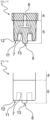
Fig.3 ] représente schématiquement une vue selon une coupe médiane longitudinale verticale d'une unité de moulage de la machine, au cours d'une première étape d'un cycle de soufflage d'un récipient, montrant notamment l'insertion de l'extrémité distale de la tige dans une préforme enfermée au sein d'un moule ; - [
Fig.4 ] représente schématiquement une vue similaire à la [Fig.3 ], au cours d'une autre étape suivante en fin du cycle de soufflage, montrant notamment l'extrémité distale de la tige introduite au sein du récipient soufflé et s'étendant jusqu'au fond dudit récipient soufflé ; - [
Fig.5 ] représente schématiquement une vue similaire à la [Fig.3 ], au cours d'une autre étape suivante du cycle de soufflage au moment du refroidissement, montrant notamment l'embout saillant de la tige d'étirage ; - [
Fig.6 ] représente schématiquement une vue de détail de la [Fig.3 ], avec la tige d'étirage positionnée au niveau du fond de la préforme ; - [
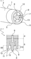
Fig.7 ] représente schématiquement une vue en perspective d'un exemple de réalisation de l'extrémité distale de la tige d'étirage, montrant notamment une jupe annulaire présentant des bords arrondis ; - [
Fig.8 ] représente schématiquement une vue selon une coupe médiane longitudinale du premier mode de la [Fig.7 ] ; - [
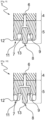
Fig.9 ] représente schématiquement une vue selon une coupe médiane longitudinale d'un deuxième mode de réalisation de l'extrémité distale de la tige d'étirage, montrant notamment la jupe annulaire présentant des orifices débouchant au travers du méplat avec une direction selon un angle par rapport à l'axe longitudinal de ladite tige, ainsi qu'en outre la jupe annulaire présentant des bords droits et biseautés ; - [
Fig. 10 ] représente schématiquement une vue selon une coupe médiane longitudinale d'un troisième mode de réalisation de l'extrémité distale de la tige d'étirage, montrant notamment la jupe annulaire présentant une forme crénelée avec des bords de crêtes arrondis et convexes et des bords de creux concaves ; - [
Fig.11 ] représente schématiquement une vue selon une coupe médiane longitudinale d'un quatrième mode de réalisation de l'extrémité distale de la tige d'étirage, montrant notamment la jupe annulaire avec un profil convergent depuis le corps de ladite tige vers son extrémité distale. - [
Fig.12 ] représente schématiquement une vue de côté d'un mode de réalisation de l'extrémité distale de la tige d'étirage, montrant notamment une jupe avec un bord annulaire inscrit dans un même plan, ainsi que l'embout et le méplat en pointillés ; - [
Fig.13 ] représente schématiquement une vue de côté encore d'un autre mode de réalisation, montrant une jupe avec des bords crénelés droits, avec des crêtes et des creux ; - [
Fig.14 ] représente schématiquement une vue de côté d'un mode de réalisation, montrant une jupe avec des bords crénelés arrondis ; et - [
Fig.15 ] représente schématiquement une vue en perspective d'un exemple de réalisation de l'extrémité distale de la tige d'étirage, montrant notamment un évidement en forme de rosace au niveau du méplat.
- [
Fig.1 ] schematically represents a simplified top view of an exemplary embodiment of a rotary type molding machine, illustrating in particular the molding units (without the blowing and stretching means) distributed around a carousel, said units blowing being, depending on their relative position relative to the inlet or outlet of the machine, in the open position or in the closed position; - [
Fig.2 ] schematically represents a partial perspective view of one of the molding units of the machine according to the exemplary embodiment of [Fig.1 ], illustrating in particular, outside the unit in the open position, an exploded view of a mold made in three parts, namely two half-molds and a mold base; - [
Fig.3 ] schematically represents a view in a vertical longitudinal median section of a molding unit of the machine, during a first step of a blowing cycle of a container, showing in particular the insertion of the distal end of the rod in a preform enclosed within a mold; - [
Fig.4 ] schematically represents a view similar to [Fig.3 ], during another next step at the end of the blowing cycle, showing in particular the distal end of the rod introduced into the blown container and extending to the bottom of said blown container; - [
Fig.5 ] schematically represents a view similar to [Fig.3 ], during another subsequent step of the blowing cycle at the time of cooling, showing in particular the protruding end of the drawing rod; - [
Fig.6 ] schematically represents a detailed view of the [Fig.3 ], with the stretching rod positioned at the bottom of the preform; - [
Fig.7 ] schematically represents a perspective view of an exemplary embodiment of the distal end of the drawing rod, showing in particular an annular skirt having rounded edges; - [
Fig.8 ] schematically represents a view in a longitudinal median section of the first mode of the [Fig.7 ] ; - [
Fig.9 ] schematically represents a view in a longitudinal median section of a second embodiment of the distal end of the drawing rod, showing in particular the annular skirt having orifices opening through the flat with a direction at an angle relative to to the longitudinal axis of said rod, as well as in addition the annular skirt having straight and beveled edges; - [
Fig. 10 ] schematically represents a view in a longitudinal median section of a third embodiment of the distal end of the drawing rod, showing in particular the annular skirt having a crenellated shape with rounded and convex ridge edges and concave hollow edges; - [
Fig.11 ] schematically represents a view in a longitudinal median section of a fourth embodiment of the distal end of the drawing rod, showing in particular the annular skirt with a converging profile from the body of said rod towards its distal end. - [
Fig.12 ] schematically represents a side view of an embodiment of the distal end of the drawing rod, showing in particular a skirt with an annular edge inscribed in the same plane, as well as the tip and the flat in dotted lines; - [
Fig.13 ] schematically represents a side view of yet another embodiment, showing a skirt with straight crenellated edges, with ridges and valleys; - [
Fig.14 ] schematically represents a side view of one embodiment, showing a skirt with rounded crenellated edges; And - [
Fig.15 ] schematically represents a perspective view of an exemplary embodiment of the distal end of the drawing rod, showing in particular a recess in the form of a rosette at the level of the flat.
Description détaillée de l'invention : Dans la suite de la description, des éléments présentant une structure identique ou des fonctions analogues seront désignés par une même référence.Detailed description of the invention: In the remainder of the description, elements having an identical structure or similar functions will be designated by the same reference.
L'invention est conçue pour être mise en oeuvre dans une installation de fabrication de récipients 2. Une telle installation comporte, usuellement, une machine de moulage telle que représentée en [
En pratique, les moules de soufflage 14 sont répartis circulairement, sous la forme d'un carrousel 170, comme visible en [
La [
Tous ces éléments sont bien connus de l'Homme du métier et ne sont pas décrits en détail pour une meilleure compréhension de l'invention.All of these elements are well known to those skilled in the art and are not described in detail for a better understanding of the invention.
On se réfère à la [
Sur la [
Comme visible sur la [
Entre le col 32 et le corps de la préforme, une collerette 33 radiale fait saillie vers l'extérieur de la préforme 3.Between the
De manière générale, la préforme 3 illustrée en [
Lors de la mise en place de la préforme dans l'installation de soufflage, l'axe Y de la tige 1 est sensiblement confondu avec l'axe de révolution de la préforme 3. Dans ce qui suit, on désignera donc indifféremment par Y l'axe de la tige 1 ou celui de la préforme 3.When placing the preform in the blowing installation, the axis Y of the
Dans ce qui suit, on qualifiera de « vertical » toute direction parallèle à l'axe de révolution de la tige et de « transversal » toute direction perpendiculaire à l'axe de révolution de la tige.In what follows, we will describe as “vertical” any direction parallel to the axis of revolution of the rod and “transverse” any direction perpendicular to the axis of revolution of the rod.
Comme représenté en [
Le corps 4 comprend également un canal intérieur 6 central s'étendant axialement et communiquant avec une pluralité d'orifices 9 par lesquels un gaz de refroidissement 10, en particulier de l'air, est injecté à l'intérieur du récipient 2 fabriqué afin de le refroidir. Les orifices 9 sont donc en communication fluidique avec le canal intérieur 6. Dans le prolongement du corps 4, au niveau de l'extrémité distale 5, la tige d'étirage 1 comprend un méplat 7. Un embout 8 fait saillie à partir de ce méplat 7.The
Comme représente en [
La [
La [
Dans des modes de réalisation, et comme représenté sur la [
Dans des modes de réalisation, le corps 4 extérieur et la jupe annulaire 11 sont obtenus d'un seul tenant. En d'autres termes, ils forment une seule et même pièce.In embodiments, the
Selon d'autres modes de réalisation, le corps 4 extérieur et la jupe annulaire 11 sont deux pièces séparées.According to other embodiments, the
Les modifications structurelles de la tige d'étirage 1 ont pour effet avantage de diriger le gaz de refroidissement 10 vers le fond du récipient 2, sur l'ensemble de sa surface inférieure, et ainsi d'améliorer l'étape de refroidissement.The structural modifications of the
L'on peut voir en [
Les orifices 9 sont par exemple de forme cylindrique et ont de préférence un diamètre compris entre 0,3 et 3 millimètres (mm). Ils peuvent également être d'une autre forme, par exemple de forme oblongue.The
Selon un mode de réalisation préféré, la surface d'injection est comprise entre 3 et 6 millimètres carrés (mm2) et n'excède pas 20 millimètres carrés (mm2). La surface d'injection correspond à la somme des diamètres des orifices 9. Elle représente la quantité de gaz de refroidissement 10 pouvant être injectée grâce à la configuration de la tige 1, comprenant des orifices 9 jouant le rôle d'orifices de restriction. Ainsi, grâce à l'invention, il est possible d'obtenir un refroidissement interne du récipient 1 formé tout en minimisant la consommation de gaz de refroidissement 10. La tige d'étirage 1 présente en effet un volume mort très faible et une conception optimisée pour le refroidissement interne d'un récipient 2 soufflé.According to a preferred embodiment, the injection surface is between 3 and 6 square millimeters (mm 2 ) and does not exceed 20 square millimeters (mm2). The injection surface corresponds to the sum of the diameters of the
La tige d'étirage 1 présente donc une pluralité d'orifices 9 disposés sur le méplat 7. L'embout 8 saillant peut être de toute forme. En particulier, ledit embout 8 peut être de forme conique, de forme conique arrondie, de forme ovoïde, de forme hémisphérique, etc.The drawing
Selon un mode de réalisation préféré, comme représenté en [
La [
Dans cet exemple de réalisation, la jupe annulaire 11 a le même diamètre que le diamètre du corps 4 de la tige d'étirage 1. Sur le méplat 7 sont disposés, autour de l'embout 8 saillant, cinq orifices 9.In this exemplary embodiment, the
En outre, comme visible sur la [
Dans un mode de réalisation préféré, la hauteur 110 de la jupe annulaire 11 est inférieure à la hauteur 80 de l'embout 8 d'une valeur comprise entre 0,5 et 4 millimètres (mm), encore plus préférentiellement d'une valeur de 1mm.In a preferred embodiment, the
Dans des modes de réalisation, la hauteur 110 de la jupe annulaire 11 varie sur l'ensemble de sa circonférence. Par exemple, la jupe annulaire 11 peut avoir des bords dentelés ou festonnés, et donc présenter des creux et des crêtes, comme visible sur la [
La [
L'étape de refroidissement est une étape additionnelle dans un procédé de fabrication de récipients en PET et en PET recyclé (« rPET »). Le flux du gaz de refroidissement 10 est représenté schématiquement à la [
Dans des modes de réalisation, comme représenté en [
Dans un mode de réalisation préféré, les orifices 9 sont orientés vers l'extérieur dans la direction de l'axe principal Y, d'une déviation de 30 degrés.In a preferred embodiment, the
L'orientation des orifices permet au gaz de refroidissement 10 de se répartir de manière homogène vers le fond de la préforme 3 et donc vers le fond du récipient 2 ainsi formé, c'est-à-dire sur l'ensemble de sa surface. En outre, cela permet d'améliorer encore le refroidissement du fond, là où ce dernier présente les températures les plus élevées, et donc là où des zones de stress, favorisées par son affaissement, sont à même de se développer.The orientation of the orifices allows the cooling
Dans un mode de réalisation préféré, la jupe 11 présente des bords arrondis et les orifices 9 de la tige sont orientés de biais.In a preferred embodiment, the
Dans des modes de réalisation, la jupe annulaire 11 de la tige d'étirage 1 présente des bords droits et biseautés. Ce mode de réalisation est illustré en [
Dans un mode de réalisation illustré en [
Dans des modes de réalisation où la jupe annulaire 11 présente des crêtes et des creux, les orifices 9 peuvent être alignés à un creux ou à une crête. Selon un mode de réalisation préféré, les orifices 9 sont alignés à une crête, afin de concentrer le gaz de refroidissement sur le fond du récipient 2.In embodiments where the
Dans une autre variante, comme illustré en [
Selon une autre variante, non représentée, le diamètre de la jupe annulaire 11 est supérieur au diamètre du corps 4 de la tige d'étirage 1. La jupe annulaire 11 a alors une forme évasée. On comprendra par « forme évasée » une forme dont la section croît. Ainsi, une portion extrême libre de jupe annulaire 11 de forme évasée signifie que la portion extrême de ladite jupe présente une section qui grandit à partir du méplat 7, jusqu'à son extrémité libre.According to another variant, not shown, the diameter of the
La [
Les
La [
La [
La [
Selon des modes de réalisation, les bords de la rosace intérieure ont une hauteur inférieure ou égale à la hauteur 110 de la jupe 11. Selon une variante, les bords de la rosace intérieure ont une hauteur inférieure, à la hauteur 80 de l'embout 8. Ce mode de réalisation permet avantageusement de canaliser le gaz de refroidissement 10 et d'améliorer encore sa direction vers le fond du récipient 2.According to embodiments, the edges of the interior rosette have a height less than or equal to the
Avantageusement, chaque orifice 9 se situe au niveau d'un sommet d'une branche de la rosace intérieure.Advantageously, each
L'invention concerne également un procédé de fabrication d'un récipient 2 par étirage soufflage mettant en oeuvre la tige 1 d'étirage précédemment décrite.The invention also relates to a method of manufacturing a
Le procédé de fabrication selon l'invention comprend au moins les étapes suivantes de :
placement d'une préforme 3 préalablement chauffée dans un moule de soufflage 14 présentant, en position de fermeture, une cavité de moulage 15 formant l'empreinte du récipient 2 à souffler ;- fermeture dudit moule de soufflage 14 ;
- soufflage de ladite préforme 3 dans le moule de soufflage 14 par l'intermédiaire d'une tuyère de soufflage 16 et, de manière sensiblement simultanée, une étape d'étirage de ladite préforme 3 par insertion de la tige d'étirage 1 à l'intérieur de ladite préforme 3 en prenant appui contre le fond 30 de ladite préforme 3 de manière à faciliter l'allongement axial de ladite préforme 3 ;
- refroidissement de l'intérieur dudit récipient 2 ainsi formé par injection d'un gaz de refroidissement 10, usuellement de l'air, par l'intermédiaire de ladite tige d'étirage 1, pourvue d'une pluralité d'orifices 9 prévus à cet effet ;
- remontée de ladite tige d'étirage 1 ;
- saisie du récipient 3 soufflé par des moyens de préhension extérieurs ;
- ouverture dudit moule de soufflage 14.
- placement of a previously
heated preform 3 in ablow mold 14 having, in the closed position, amolding cavity 15 forming the imprint of thecontainer 2 to be blown; - closing said
blow mold 14; - blowing of said
preform 3 in theblow mold 14 via ablow nozzle 16 and, substantially simultaneously, a step of stretching saidpreform 3 by inserting the stretchingrod 1 into the interior of saidpreform 3 by bearing against the bottom 30 of saidpreform 3 so as to facilitate the axial elongation of saidpreform 3; - cooling of the interior of said
container 2 thus formed by injection of a coolinggas 10, usually air, via said stretchingrod 1, provided with a plurality oforifices 9 provided for this effect ; - raising of said stretching
rod 1; - gripping the
blown container 3 by external gripping means; - opening of said
blow mold 14.
La [
La fabrication d'un récipient 2 est réalisée par soufflage d'une préforme 3 chaude dans un moule 14 d'une unité 18 de moulage de l'installation au moyen d'au moins un fluide sous pression, généralement de l'air.The manufacture of a
Dans l'exemple de réalisation, la fabrication des récipients 2 est réalisée par étirage-soufflage. Les moyens de soufflage intègrent avantageusement au moins une tige d'étirage 1.In the exemplary embodiment, the
La tige d'étirage 1 est entraînée axialement, le long de l'axe Y, en déplacement par des moyens d'entraînement associés (non représentés).The drawing
La tige d'étirage 1 est donc montée coulissante axialement pour être introduite à l'intérieur de la préforme 3 à travers l'ouverture délimitée radialement par son col 32, un espace annulaire étant laissé libre entre le col 32 et la tige 1 pour permettre le passage du fluide de soufflage.The stretching
La tige d'étirage 1 est montée mobile axialement entre au moins une première position haute et une deuxième position basse.The stretching
Dans la première position, la tige 1 s'étend hors du moule 14 et, dans la deuxième position, dite position basse, la tige 1 est déplacée vers le bas pour venir étirer axialement la préforme 3 à l'intérieur du moule 14, lors du soufflage.In the first position, the
Les
Une première étape, comme visible sur la [
Une fois la préforme 3 en position et le moule 14 fermé, comme visible sur la [
Dans un mode de réalisation préféré, la position basse de la tige d'étirage 1 correspond à une position où l'embout 8 touche le fond de la préforme 3.In a preferred embodiment, the low position of the stretching
Dans d'autres modes de réalisation, la position basse de la tige d'étirage 1 correspond à une position où l'embout 8 est légèrement en retrait par rapport au fond de la préforme 3.In other embodiments, the low position of the stretching
Sensiblement simultanément à l'insertion de la tige d'étirage 1 dans la préforme 3, vient l'étape de soufflage, ou d'étirage soufflage, au cours de laquelle un fluide (par exemple de l'air) est injecté dans la préforme 3, d'abord à une pression moyenne dite de pré-soufflage, comprise entre 5 bars et 15 bars, tout en déplaçant la tige d'étirage 1 depuis sa position haute vers sa position basse déployée.Substantially simultaneously with the insertion of the
L'étape de soufflage se termine par une augmentation momentanée de la pression jusqu'à une pression élevée, supérieure à la pression de pré-soufflage pour bien plaquer la matière contre la cavité 15 du moule de soufflage 14 et ainsi lui imprimer l'empreinte du récipient 2, comme représenté sur la [
La tige d'étirage est maintenue en position déployée pour éviter tout glissement intempestif de la matière sur le fond du moule tant que la pression dans le récipient n'a pas atteint la pression de soufflage.The drawing rod is held in the deployed position to prevent any unwanted sliding of the material on the bottom of the mold until the pressure in the container has reached the blowing pressure.
Suit une étape de refroidissement réalisée par l'injection d'un gaz de refroidissement 10 vers le fond du récipient 2 ainsi formé. La tige d'étirage 1 est alors en position basse, comme visible sur la [
Selon des modes de réalisation, l'étape de refroidissement, dite aussi étape de balayage, consiste à accélérer le refroidissement du récipient 2 par l'intérieur. Dans un mode de réalisation illustré en [
Dans des modes de réalisation, la tige d'étirage 1 est déplacée axialement à l'intérieur de la cavité 15 de moulage au cours de ladite étape de refroidissement pour réaliser axialement un balayage de la cavité 15 de moulage, par exemple du haut vers le bas et réciproquement, suivant une course déterminée.In embodiments, the drawing
Dans des variantes, la tige d'étirage 1 est entrainée sélectivement en rotation pour réaliser un balayage circulaire de chaque cavité 15 de moulage des moules 14 refroidis au moyen dudit au moins un gaz de refroidissement 10.In variants, the drawing
La tige d'étirage 1 est par exemple entraînée de manière continue sur elle-même pour réaliser un balayage sur 360° degrés ou en variante séquentiellement.The stretching
L'entraînement en rotation de la tige d'étirage 1 s'effectue avantageusement en combinaison avec le déplacement axial de ladite tige, l'ensemble étant contrôlé en commandant sélectivement les moyens d'entraînement.The rotational drive of the stretching
Enfin, à l'issue de l'étape de refroidissement, le moule 14 est ouvert et le récipient 2 formé en est évacué, ce qui boucle le cycle. Un nouveau cycle peut alors commencer avec l'introduction d'une nouvelle préforme 3.Finally, at the end of the cooling step, the
La mise en oeuvre d'une tige d'étirage 1 selon l'invention permet une meilleure maîtrise de l'étape de refroidissement. Il est possible, par ce contrôle amélioré, d'augmenter les cadences de soufflage, tout en limitant la diffusion de chaleur de l'interne vers l'externe. Par ailleurs, un refroidissement amélioré du fond du récipient 2 permet de limiter les risques d'affaissement.The use of a
En outre, l'utilisation d'une telle tige d'étirage 1 offre une plus grande souplesse dans l'utilisation des préformes, notamment celles dont la forme ne serait pas parfaitement adaptée à la bouteille.In addition, the use of such a
Il a enfin été constaté que l'utilisation de la tige d'étirage 1 conformément à l'invention permet d'accélérer le refroidissement du fond 30 de la préforme 3, tout en réduisant le nombre de récipients 2 de qualité insatisfaisante. Ceci est directement lié à la conception de la tige d'étirage 1, qui comprend à présent une jupe annulaire 11, permettant de diriger le gaz de refroidissement 10 de manière précise et contrôlée vers le fond du récipient 2 ainsi formé.It was finally noted that the use of the
Claims (10)
Applications Claiming Priority (1)
| Application Number | Priority Date | Filing Date | Title |
|---|---|---|---|
| FR2203421A FR3134534B1 (en) | 2022-04-13 | 2022-04-13 | Drawing and cooling rod for container forming |
Publications (1)
| Publication Number | Publication Date |
|---|---|
| EP4261006A1 true EP4261006A1 (en) | 2023-10-18 |
Family
ID=82319645
Family Applications (1)
| Application Number | Title | Priority Date | Filing Date |
|---|---|---|---|
| EP23159164.5A Pending EP4261006A1 (en) | 2022-04-13 | 2023-02-28 | Stretching and cooling rod for forming containers |
Country Status (5)
| Country | Link |
|---|---|
| US (1) | US12023843B2 (en) |
| EP (1) | EP4261006A1 (en) |
| CN (1) | CN116901403A (en) |
| FR (1) | FR3134534B1 (en) |
| MX (1) | MX2023004239A (en) |
Citations (5)
| Publication number | Priority date | Publication date | Assignee | Title |
|---|---|---|---|---|
| EP0036844A1 (en) * | 1980-03-21 | 1981-09-30 | Borrini Geo | Method of manufacturing plastic containers by blow molding without any waste and machine for carrying out said method |
| US5213752A (en) * | 1990-08-14 | 1993-05-25 | Nissei Asb Machine Co., Ltd. | Process of stretch-blow molding |
| JP2001088202A (en) | 1999-09-22 | 2001-04-03 | Hokkai Can Co Ltd | Blow molding method |
| US20110193271A1 (en) * | 2009-12-17 | 2011-08-11 | Eastman Chemical Company | Method and apparatus for stretch blow molding a container |
| US20210107205A1 (en) * | 2019-10-15 | 2021-04-15 | Pretium Packaging, L.L.C. | System and method for forming containers using blow mold and electric heating elements |
Family Cites Families (3)
| Publication number | Priority date | Publication date | Assignee | Title |
|---|---|---|---|---|
| US4889752A (en) * | 1987-05-29 | 1989-12-26 | Devtech, Inc. | One piece self-standing blow molded plastic containers |
| DE102007061659A1 (en) * | 2007-12-18 | 2009-06-25 | Krones Ag | Stretching rod, apparatus and method for producing hollow bodies |
| DE102015106615A1 (en) * | 2015-04-29 | 2016-11-03 | Krones Ag | Method and device for forming plastic preforms with container cooling |
-
2022
- 2022-04-13 FR FR2203421A patent/FR3134534B1/en active Active
-
2023
- 2023-02-28 EP EP23159164.5A patent/EP4261006A1/en active Pending
- 2023-04-04 CN CN202310354418.1A patent/CN116901403A/en active Pending
- 2023-04-05 US US18/131,162 patent/US12023843B2/en active Active
- 2023-04-12 MX MX2023004239A patent/MX2023004239A/en unknown
Patent Citations (5)
| Publication number | Priority date | Publication date | Assignee | Title |
|---|---|---|---|---|
| EP0036844A1 (en) * | 1980-03-21 | 1981-09-30 | Borrini Geo | Method of manufacturing plastic containers by blow molding without any waste and machine for carrying out said method |
| US5213752A (en) * | 1990-08-14 | 1993-05-25 | Nissei Asb Machine Co., Ltd. | Process of stretch-blow molding |
| JP2001088202A (en) | 1999-09-22 | 2001-04-03 | Hokkai Can Co Ltd | Blow molding method |
| US20110193271A1 (en) * | 2009-12-17 | 2011-08-11 | Eastman Chemical Company | Method and apparatus for stretch blow molding a container |
| US20210107205A1 (en) * | 2019-10-15 | 2021-04-15 | Pretium Packaging, L.L.C. | System and method for forming containers using blow mold and electric heating elements |
Also Published As
| Publication number | Publication date |
|---|---|
| CN116901403A (en) | 2023-10-20 |
| MX2023004239A (en) | 2023-10-16 |
| US12023843B2 (en) | 2024-07-02 |
| US20230330911A1 (en) | 2023-10-19 |
| FR3134534B1 (en) | 2024-03-08 |
| FR3134534A1 (en) | 2023-10-20 |
Similar Documents
| Publication | Publication Date | Title |
|---|---|---|
| EP1795328B1 (en) | Method and device for moulding containers, particularly bottles, by drawing-blowing thermoplastic material with a petaloid bottom | |
| EP0768944B1 (en) | Device for sealing a plastic container preform to a blow moulding nozzle, and container blow moulding machine provided therewith | |
| CH370231A (en) | Process for manufacturing a hollow plastic article, tooling for carrying out this process and hollow article obtained by this process | |
| EP1855868B1 (en) | Device for gripping the neck of hollow bodies and hollow body transport installation which is equipped with such devices | |
| FR3045446A1 (en) | ANGULAR INDEXATION OF A NON-UNIFORMLY HEATED PREFORM BY MEASURING TEMPERATURE | |
| FR2921293A1 (en) | Container i.e. heat-resistant container, fabricating method for packaging field, involves performing depressurization operation after blowing operation and before scavenging operation so as to depressurize container | |
| EP0059016A1 (en) | Thermoplastic paraison and method for blow moulding a hollow article from such a paraison | |
| EP0000801B1 (en) | Method for producing oriented hollow bodies | |
| FR3045445A1 (en) | LARGE EVENTS MOLDING BOTTOM FOR FORMING A CONTAINER | |
| FR1450764A (en) | Improvements to plastic bottles | |
| EP4261006A1 (en) | Stretching and cooling rod for forming containers | |
| EP4261007A1 (en) | Stretching rod for forming containers | |
| WO2017103361A1 (en) | Preform with a concave bottom and an evolving thickness | |
| WO2024141602A1 (en) | Method for cooling a container produced by stretch blow moulding | |
| EP3787870B1 (en) | Method for forming a container made of thermoplastic material by biaxial stretching | |
| EP3846990B1 (en) | Preform for a container made of plastic material | |
| EP1779993B1 (en) | Apparatus and method of manufacturing a thermoplastic container by blow moulding | |
| EP3389971B1 (en) | Preform provided with a concave body portion | |
| FR3022824A1 (en) | STRETCH ROD FOR A STRETCH MOLDING DEVICE FOR BLOWING CONTAINERS, ESPECIALLY BOTTLES OF PLASTIC MATERIAL | |
| EP1280646B1 (en) | Mould for injection moulding of a flexible tube and injection moulding method | |
| CA2928809C (en) | Preform having a star-shaped bottom and corresponding container | |
| WO2024141556A1 (en) | Container having an improved petaloid bottom, and mould bottom for producing such a container | |
| WO2024037944A1 (en) | Concentric mould cooling | |
| EP2925504B1 (en) | Method of manufacturing fuel tanks by blow moulding | |
| FR2766119A1 (en) | Plastics cosmetic product tube |
Legal Events
| Date | Code | Title | Description |
|---|---|---|---|
| PUAI | Public reference made under article 153(3) epc to a published international application that has entered the european phase |
Free format text: ORIGINAL CODE: 0009012 |
|
| STAA | Information on the status of an ep patent application or granted ep patent |
Free format text: STATUS: THE APPLICATION HAS BEEN PUBLISHED |
|
| AK | Designated contracting states |
Kind code of ref document: A1 Designated state(s): AL AT BE BG CH CY CZ DE DK EE ES FI FR GB GR HR HU IE IS IT LI LT LU LV MC ME MK MT NL NO PL PT RO RS SE SI SK SM TR |
|
| STAA | Information on the status of an ep patent application or granted ep patent |
Free format text: STATUS: REQUEST FOR EXAMINATION WAS MADE |
|
| 17P | Request for examination filed |
Effective date: 20240418 |
|
| RBV | Designated contracting states (corrected) |
Designated state(s): AL AT BE BG CH CY CZ DE DK EE ES FI FR GB GR HR HU IE IS IT LI LT LU LV MC ME MK MT NL NO PL PT RO RS SE SI SK SM TR |
|
| GRAP | Despatch of communication of intention to grant a patent |
Free format text: ORIGINAL CODE: EPIDOSNIGR1 |
|
| STAA | Information on the status of an ep patent application or granted ep patent |
Free format text: STATUS: GRANT OF PATENT IS INTENDED |
|
| RIC1 | Information provided on ipc code assigned before grant |
Ipc: B29L 31/00 20060101ALN20240627BHEP Ipc: B29K 67/00 20060101ALN20240627BHEP Ipc: B29C 49/06 20060101ALN20240627BHEP Ipc: B29C 49/66 20060101ALI20240627BHEP Ipc: B29C 49/12 20060101AFI20240627BHEP |
|
| INTG | Intention to grant announced |
Effective date: 20240710 |