EP4260970A1 - Hand-held electric tool - Google Patents
Hand-held electric tool Download PDFInfo
- Publication number
- EP4260970A1 EP4260970A1 EP23167381.5A EP23167381A EP4260970A1 EP 4260970 A1 EP4260970 A1 EP 4260970A1 EP 23167381 A EP23167381 A EP 23167381A EP 4260970 A1 EP4260970 A1 EP 4260970A1
- Authority
- EP
- European Patent Office
- Prior art keywords
- section
- hand
- main body
- electric tool
- held electric
- Prior art date
- Legal status (The legal status is an assumption and is not a legal conclusion. Google has not performed a legal analysis and makes no representation as to the accuracy of the status listed.)
- Granted
Links
Images


Classifications
-
- B—PERFORMING OPERATIONS; TRANSPORTING
- B23—MACHINE TOOLS; METAL-WORKING NOT OTHERWISE PROVIDED FOR
- B23D—PLANING; SLOTTING; SHEARING; BROACHING; SAWING; FILING; SCRAPING; LIKE OPERATIONS FOR WORKING METAL BY REMOVING MATERIAL, NOT OTHERWISE PROVIDED FOR
- B23D57/00—Sawing machines or sawing devices not covered by one of the preceding groups B23D45/00 - B23D55/00
- B23D57/02—Sawing machines or sawing devices not covered by one of the preceding groups B23D45/00 - B23D55/00 with chain saws
- B23D57/023—Sawing machines or sawing devices not covered by one of the preceding groups B23D45/00 - B23D55/00 with chain saws hand-held or hand-operated
-
- B—PERFORMING OPERATIONS; TRANSPORTING
- B27—WORKING OR PRESERVING WOOD OR SIMILAR MATERIAL; NAILING OR STAPLING MACHINES IN GENERAL
- B27B—SAWS FOR WOOD OR SIMILAR MATERIAL; COMPONENTS OR ACCESSORIES THEREFOR
- B27B17/00—Chain saws; Equipment therefor
-
- B—PERFORMING OPERATIONS; TRANSPORTING
- B25—HAND TOOLS; PORTABLE POWER-DRIVEN TOOLS; MANIPULATORS
- B25F—COMBINATION OR MULTI-PURPOSE TOOLS NOT OTHERWISE PROVIDED FOR; DETAILS OR COMPONENTS OF PORTABLE POWER-DRIVEN TOOLS NOT PARTICULARLY RELATED TO THE OPERATIONS PERFORMED AND NOT OTHERWISE PROVIDED FOR
- B25F5/00—Details or components of portable power-driven tools not particularly related to the operations performed and not otherwise provided for
-
- B—PERFORMING OPERATIONS; TRANSPORTING
- B27—WORKING OR PRESERVING WOOD OR SIMILAR MATERIAL; NAILING OR STAPLING MACHINES IN GENERAL
- B27G—ACCESSORY MACHINES OR APPARATUS FOR WORKING WOOD OR SIMILAR MATERIALS; TOOLS FOR WORKING WOOD OR SIMILAR MATERIALS; SAFETY DEVICES FOR WOOD WORKING MACHINES OR TOOLS
- B27G19/00—Safety guards or devices specially adapted for wood saws; Auxiliary devices facilitating proper operation of wood saws
- B27G19/003—Safety guards or devices specially adapted for wood saws; Auxiliary devices facilitating proper operation of wood saws for chain saws
Definitions
- the present invention relates to the field of small industrial appliances, in particular to a hand-held electric tool.
- An objective of the present invention is to provide a hand-held electric tool, wherein the bottom of the main body of the hand-held electric tool is provided with a bottom wall, and a chip removal hole is provided in the bottom wall, which means that the bottom of the hand-held electric tool is substantially closed, so such a bottom arrangement allows the removal of chips while preventing a user's hand from being inadvertently extended into the housing and contacting a component operating at a high speed.
- the rear side of the chip removal hole of the hand-held electric tool is provided with a protective portion, so that chips removed through the chip removal hole are blocked by the protective portion, without reaching the grip section, which offers considerable advantages in terms of safety and hygiene.
- a hand-held electric tool of the present invention is further provided with a first rest block located at the top for a user's fingers to rest, and a second rest block located at the bottom for the object to be worked to rest, wherein these rest blocks can improve operational stability, and the first rest block can also prevent the user's fingers from crossing the front end of the housing and contacting an operating component.
- a hand-held electric tool comprising:
- the chip removal hole is oriented forwards and downwards, preferably with the inner wall of the housing, which is located behind the chip removal hole, extending forwards and downwards.
- the chip removal hole is oriented backwards and downwards
- the main body section comprises a guide member located near the chip removal hole to guide the removal of chips backwards and downwards from the main body section, wherein, preferably, the guide member comprises a first guide wall and a second guide wall that is located below the first guide wall and has a guide direction different from that of the first guide wall, the second guide wall extending backwards and downwards.
- the operating component comprises a saw chain that rotates on its plane of extension, the first guide wall facing and being shaped to fit a portion of the saw chain.
- the protective portion comprises a downwardly and forwardly extending baffle located at its frontmost portion.
- the protective portion further comprises a protective portion cross member extending backwards from the baffle, defining a space for accommodating a user's hand between the protective portion and the grip section.
- the housing further comprises a battery engagement section located at the rear end of the grip section and extending substantially perpendicular to the grip section, preferably with the protective portion extending to be joined to the lower end of the battery engagement section.
- the width of the baffle is greater than that of the housing, wherein preferably the overall width of the protective portion is greater than the width of the grip section, and preferably the baffle of the protective portion is wider than other parts.
- the grip section extends backwards and downwards from the main body section, preferably with the protective portion cross member being substantially parallel to the direction of extension of the grip section.
- the chip removal hole is adjacent to the front surface of the baffle, wherein preferably the chip removal hole has a length that is 1/8-1/4 that of the main body section, preferably the chip removal hole has a width that is 1/4-1/2 that of the main body section, and preferably the chip removal hole is a substantially circular hole or a substantially square hole.
- the operating component comprises a saw chain that rotates on its plane of extension, the saw chain comprising a bottom section, a top section, as well as a front connecting section and a rear connecting section that are connected therebetween, wherein the bottom section of the saw chain moves backwards during the operation.
- the top side of the main body section is provided with a first rest block, which is configured to allow a user's hand to rest against the rear end face of the first rest block, wherein, preferably, the width of the rear end face of the first rest block is 1/5-1/3 that of the main body section, and preferably, the top surface of the first rest block is configured as an L-shaped structure.
- a second rest block is arranged at the frontmost position on the bottom side of the main body section, and the second rest block is configured such that its front end face abuts the object to be worked during use, wherein, preferably, the second rest block extends over the almost complete width of the main body section, and preferably, the length of the second rest block is 1/5-1/3 that of the main body section.
- the main body section comprises a first section and a second section that are adjacent to each other, wherein the direction of extension of the first section forms an angle between 100-160 degrees, preferably between 100-150 degrees, and more preferably between 140-150 degrees with the direction of extension of the second section, the second section being specifically a motor section.
- the first rest block is located at least partially in the first section, preferably the first rest block being located substantially in the first section.
- Fig. 1-Fig. 6 are preferred embodiments of a hand-held electric tool according to the present invention, which may be, for example, a hand-held trimming device or a hand-held cutting device.
- directional and positional terms in the present invention should be understood to mean relative directions and positions, not absolute directions and positions.
- the directional terms and positional terms used in the present invention are explainable with reference to the exemplary structures shown in Fig. 1-Fig. 6 .
- "front side” and “forwards” refer to the direction that extends in direction D1 and, when the user correctly holds the hand-held electric tool, is away from the user (that is, the direction pointing to the left as shown in Fig.
- “rear side” and “backwards” refer to the direction that extends in direction D1 and, when the user correctly holds the hand-held electric tool, faces the user (that is, the direction pointing to the right as shown in Fig. 1 ); terms like “top side” and “above” refer to the upward position and direction in direction D2 as shown in Fig. 1 ; terms like “bottom side” and “below” refer to the downward position and direction in direction D2 as shown in Fig. 1 ; the width of a component refers to the size of the component in direction D3; and the length of a component refers to the size of the component in direction D1.
- the terms “first” and “second” as used in the present invention are only intended to distinguish between names, rather than implying any order of precedence, wherein, for example, the presence of a second rest block does not necessarily mean that a first rest block exists.
- a hand-held electric tool 100 of the present invention comprises a housing 10 and an operating component 20.
- the housing 10 and the components located therein constitute the main structure of the hand-held electric tool 100.
- the housing 10 may have a main body section 11 and a grip section 12 extending backwards from the main body section 11, as well as a battery engagement section 16 located at the rear end of the grip section 12 and extending perpendicular to the grip section 12.
- the main body section 11 may further comprise a first section 111 and a second section 112 that are adjacent to each other, wherein the second section 112 is configured to accommodate the motor section 15 of the electric machine, for example.
- the direction of extension of the first section 111 forms an angle between 100-160 degrees, preferably between 100-150 degrees, and more preferably between 140-150 degrees with the direction of extension of the second section 112.
- the housing of the main body section 11 may comprise a first housing portion 113, a second housing portion 114, and a third housing portion 115 arranged sequentially in a third direction D3.
- the front end of the main body section 11 is provided with a mounting interface, and the operating component 20 may be mounted at the mounting interface of the housing 10 and protrude forwards from the housing 10.
- the grip section 12 may extend backwards and downwards from the main body section 11, such that an obtuse angle is formed between the direction of extension of the grip section 12 and the direction of extension of the operating component 20.
- a battery can be slid in a direction of extension parallel to the battery engagement section 16 to the position where it engages the battery engagement section 16.
- the operating component 20 is used for cutting and trimming objects to be worked, such as woods and branches of trees.
- the operating component 20 comprises, for example, a saw chain 21 supported by a support plate 214, the saw chain 21 being rotatable around the support plate 214 within a plane defined by the first direction D1 and the second direction D2 to cut an object.
- the top of the saw chain 21 is provided with a protective cover 22, the protective cover 22 being removable from the housing 10 or pivotally openable relative to the housing 10.
- the saw chain 21 comprises a bottom section 211, a top section 212, as well as a front connecting section 213 and a rear connecting section 215 that are connected therebetween (as shown in Fig. 4A and Fig. 4B , the rear connecting section 215 may be located within the housing 10), wherein, during the operation, the bottom section 211 moves backwards and the top section 212 moves forwards.
- the rear connecting section 215 of the saw chain 21 rotates around a transmission member 17 (see Fig. 4A and Fig. 4B ) to be driven by the transmission member 17, the transmission member 17 can be connected to the output shaft of the motor.
- the chip removal hole 11b is positioned just downstream of the movement direction of the bottom section 211 of the saw chain 21 to allow the removal of chips, thus preventing the accumulation of chips in the housing 10.
- the bottom of the housing 10 is substantially closed, on which only one chip removal hole 11b is provided, the chip removal hole 11b being preferably located at the rearmost end of the bottom wall 11a of the main body section 11.
- the bottom walls of the second housing portion 114 and the third housing portion 115 are complete, and only the rear end of the bottom wall of the first housing portion 113 is provided with an opening for the formation of a chip removal hole 11b.
- the chip removal hole 11b may have a small opening area, wherein the length of the chip removal hole 11b may be 1/8-1/4 that of the main body section 11, for example, and the length of the chip removal hole 11b may be 1/5 that of the main body section 11, for example; the width of the chip removal hole 11b may be 1/4-1/2 that of the main body section 11, wherein the width of the chip removal hole 11b may be 1/3 that of the main body section 11, for example.
- the chip removal hole 11b has a regular shape, being, for example, a substantially circular hole or, as shown in Fig. 3 , a substantially square hole.
- the substantially closed bottom structure of the hand-held electric tool 100 allows the removal of chips while preventing a user's hand from being inadvertently extended into the housing 10 and contacting the operating component 20 rotating at a high speed.
- the rotary speed of the saw chain 21 may be as high as 3-8 m/s, preferably 4-8 m/s and more preferably 6 m/s.
- the first housing portion 113 has a forwardly and downwardly extending inner wall 113b located behind the chip removal hole 11b, the inner wall 113b being usable as a guide wall to guide chips forwards and downwards.
- the bottom wall 113a of the first housing portion 113 forms a protective wall to prevent a user's hand from being extended upwards into the housing.
- the structure shown in Fig. 4B is substantially the same as that shown in Fig. 4A , except that a guide member 15 is further provided in Fig. 4B to guide chips backwards and downwards until they are removed through the chip removal hole 11b.
- the direction of removal of chips is also indicated by arrows, with the endmost arrow portion having a backward component and a downward component, so it is clear that the chip removal hole 11b is oriented downwards and backwards.
- the guide member 15 comprises a first guide wall 151 and a second guide wall 152 that is located below the first guide wall 151 and has a guide direction different from that of the first guide wall 151, the second guide wall 152 extending backwards and downwards. More preferably, the first guide wall 151 and the rear connecting section 215 of the saw chain 21 face each other and are shaped to fit each other, so that the first guide wall 151 is a curved wall, while the second guide wall 152 may be a straight wall.
- the hand-held electric tool 100 of the present application is provided with a protective portion 30 that extends downwards at least partially behind the chip removal hole 1 1b (that is, at the bottom end at the position where the main body section 11 joins the grip section 12), and the protective portion 30 can separate the chip removal hole 11b from the grip section 12 for the user to grasp, so that chips removed through the chip removal hole 11b do not contact the user's hand.
- the protective portion 30 comprises, for example, a baffle 31 directly connected to the rear side of the chip removal hole 11b.
- the baffle 31 may extend downwards and forwards to enhance the effect of chip blockage.
- the protective portion 30 may be just a downwardly extending baffle as described above, but in some embodiments, with continued reference to Fig. 1-Fig. 3 , the protective portion 30 may extend as a whole towards the battery engagement section 16. It should be noted that the backward extension of the protective portion 30 as a whole does not mean that each portion thereof extends backwards, wherein, for example, the frontmost portion of the protective portion 30, which serves as the baffle 31, may partially extend forwards.
- the protective portion 30, the grip section 12, and the battery engagement section 16 may jointly define a ring shape that closes on the plane defined by direction D1 and direction D2, and a user's hand can extend into the ring.
- the protective portion 30 further comprises a protective portion cross member 33 that is parallel to the direction of extension of the grip section 12 and a transition section 32 connected between the protective portion cross member 33 and the baffle 31.
- the protective portion cross member 33 constitutes the main body of the protective portion 30, wherein, for example, the length of the protective portion cross member 33 may be greater than 1/2 or 2/3 of the overall length of the protective portion.
- both the baffle 31 and the protective portion cross member 33 can have a specific shape or direction of extension (for example, the baffle 31 extends downwards and forwards, and the protective portion cross member 33 is parallel to the direction of extension of the grip section 12), and there may be no limitations on the direction of extension of the transition section 32, as long as the protective portion cross member 33 can be connected to the baffle 31.
- Setting the protective portion cross member 33 to be parallel to the direction of extension of the grip section 12 can increase the space for accommodating the user's hand, thus bringing greater comfortableness to the user.
- the protective portion 30 extends from the position of engagement between the main body section 11 and the grip section 12 to the bottom end of the battery engagement section 16, in another embodiment not shown, there may be a gap between the protective portion 30 and the battery engagement section 16, which means that the area for accommodating the user's hand may be an unclosed structure.
- the protective portion 30, instead of being used to form a closed ring shape, may also open to a certain extent, which means that the protective portion cross member 33 may form a cantilever structure.
- the baffle 31 may be set to have a large width, for example, by making the width of the baffle 31 greater than that of the housing 10. More preferably, the protective portion 30 may also be arranged to have a large width as a whole. A comparison between the width of the protective portion 30 and that of the housing 10 is shown in Fig. 5 , and as is clear from Fig. 5 , the width of the protective portion 30 is greater than that of the housing 10, especially that of the grip section 12, wherein, for example, the width of the protective portion 30 may be 2-3 times that of the grip section 12.
- the protective portion 30 may have an increased width at the baffle 31, and the width of the baffle 31 may be greater than that of the protective portion cross member 33 and that of the transition section 32.
- the housing 10 of the hand-held electric tool 100 is further provided with structures that can improve operational stability and safety.
- the top side of the main body section 11 is provided with a first rest block 13, the first rest block 13 being configured to allow the user's hand to rest against the rear end face 131 of the first rest block 13.
- a user can extend his/her index finger, middle finger, ring finger, and little finger into the annular space defined by the protective portion 30, the grip section 12, and the battery engagement section 16, while resting his/her thumb against the rear end face 131 of the first rest block 13; alternatively, the user can rest his/her index finger against the rear end face of the first rest block 13.
- the first rest block 13 is located at least partially in the first section 111 of the main body section 11, and more preferably, the first rest block 13 is located substantially in the first section 111.
- the first rest block 13 since the first rest block 13 only needs to abut and contact the user's fingers, the first rest block 13 does not need to have a large width, wherein, as shown in Fig. 5 , for example, the width of the rear end face 131 of the first rest block 13 may be 1/5-1/3 that of the main body section 11.
- the first rest block 13 is configured with an L-shaped top surface, and the portion of the L-shaped structure extending in the third direction D3 serves as a portion that abuts and contacts the user's fingers; the portion of the L-shaped structure extending in the first direction D1 serves as a reinforcing rib.
- the first rest block 13 besides improving operational stability, prevents the user's fingers from crossing the front end of the housing 10 and contacting an operating component. Moreover, the L-shaped first rest block 13 does not prevent the protective cover 22 from springing open.
- a second rest block 141 is provided at the frontmost position on the bottom side of the main body section 11, and the second rest block 141 is configured such that its front end face 141 abuts the object to be worked during use. Since an object to be worked is usually large, increasing the area of contact with the object to be worked can improve the stability of the engagement, so preferably the second rest block 141 extends over the almost complete width of the main body section 11, which means that the width of the second rest block 141 is substantially equal to that of the main body section 11.
- the length of the second rest block 141 is most preferably 1/5-1/3 that of the main body section 11, wherein it is comprehensible that if the second rest block 141 has a small length, it easily breaks due to insufficiency of stiffness, while if the second rest block 141 is too long, the housing 10 of the hand-held electric tool 100 is heavy.
- the bottom of the main body of a hand-held electric tool is provided with a bottom wall, and a chip removal hole is provided in the bottom wall, which means that the bottom of the hand-held electric tool is substantially closed, so such a bottom arrangement allows the removal of chips while preventing a user's hand from being inadvertently extended into the housing and contacting a component operating at a high speed.
- the rear side of the chip removal hole of the hand-held electric tool is provided with a protective portion, so that chips removed through the chip removal hole are blocked by the protective portion, without reaching the grip section, which offers considerable advantages in terms of safety and hygiene.
- the present invention provides preferred settings of the dimensions of various components and structures, making the hand-held electric tool safer and more comfortable.
- a hand-held electric tool of the present invention is further provided with a first rest block located at the top for a user's fingers to rest, and a second rest block located at the bottom for the object to be worked to rest, wherein these rest blocks can improve operational stability, and the first rest block can also prevent the user's fingers from crossing the front end of the housing and contacting an operating component.
Landscapes
- Life Sciences & Earth Sciences (AREA)
- Engineering & Computer Science (AREA)
- Mechanical Engineering (AREA)
- Wood Science & Technology (AREA)
- Forests & Forestry (AREA)
- Sawing (AREA)
- Manipulator (AREA)
Abstract
Description
- The present invention relates to the field of small industrial appliances, in particular to a hand-held electric tool.
- When a common hand-held electric tool currently available on the market is used to cut or chip an object, some chips are generated, which are usually brought into the housing and then removed from the housing as its operating components (such as the saw chain and blades) move. Generally, the bottom of the housing is fully open for the removal of chips, and a user's hand can easily come into contact with the high-speed saw chain, blades, or another structure inside the housing through such an open bottom, which poses substantial safety risks. Moreover, after being removed from the housing, chips may, due to inertia, continue to move at a high speed and fall onto the user's hands, adversely affecting the user's health and safety. In another aspect, since the external structure of an existing hand-held electric tool is not well designed, the hand-held electric tool is very stable and easily shakes during operation.
- Therefore, it is necessary to provide a hand-held electric tool to at least partially solve the above-mentioned problems.
- An objective of the present invention is to provide a hand-held electric tool, wherein the bottom of the main body of the hand-held electric tool is provided with a bottom wall, and a chip removal hole is provided in the bottom wall, which means that the bottom of the hand-held electric tool is substantially closed, so such a bottom arrangement allows the removal of chips while preventing a user's hand from being inadvertently extended into the housing and contacting a component operating at a high speed. The rear side of the chip removal hole of the hand-held electric tool is provided with a protective portion, so that chips removed through the chip removal hole are blocked by the protective portion, without reaching the grip section, which offers considerable advantages in terms of safety and hygiene.
- On the other hand, the present invention provides preferred settings of the dimensions of various components and structures, making the hand-held electric tool safer and more comfortable. A hand-held electric tool of the present invention is further provided with a first rest block located at the top for a user's fingers to rest, and a second rest block located at the bottom for the object to be worked to rest, wherein these rest blocks can improve operational stability, and the first rest block can also prevent the user's fingers from crossing the front end of the housing and contacting an operating component.
- According to one aspect of the present invention, a hand-held electric tool is provided, comprising:
- a housing having a main body section and a grip section extending towards the rear side from the main body section, wherein the front end of the main body section is provided with a mounting interface;
- an operating component mounted at the mounting interface of the housing and protruding from the housing, wherein
- a chip removal hole is formed in the bottom wall of the main body section of the housing, and a protective portion that extends downwards at least partially is provided at the bottom end at the position where the main body section joins the grip section.
- In one embodiment, the chip removal hole is oriented forwards and downwards, preferably with the inner wall of the housing, which is located behind the chip removal hole, extending forwards and downwards.
- In one embodiment, the chip removal hole is oriented backwards and downwards, and the main body section comprises a guide member located near the chip removal hole to guide the removal of chips backwards and downwards from the main body section, wherein, preferably, the guide member comprises a first guide wall and a second guide wall that is located below the first guide wall and has a guide direction different from that of the first guide wall, the second guide wall extending backwards and downwards.
- In one embodiment, the operating component comprises a saw chain that rotates on its plane of extension, the first guide wall facing and being shaped to fit a portion of the saw chain.
- In one embodiment, the protective portion comprises a downwardly and forwardly extending baffle located at its frontmost portion.
- In one embodiment, the protective portion further comprises a protective portion cross member extending backwards from the baffle, defining a space for accommodating a user's hand between the protective portion and the grip section.
- In one embodiment, the housing further comprises a battery engagement section located at the rear end of the grip section and extending substantially perpendicular to the grip section, preferably with the protective portion extending to be joined to the lower end of the battery engagement section.
- In one embodiment, the width of the baffle is greater than that of the housing, wherein preferably the overall width of the protective portion is greater than the width of the grip section, and preferably the baffle of the protective portion is wider than other parts.
- In one embodiment, the grip section extends backwards and downwards from the main body section, preferably with the protective portion cross member being substantially parallel to the direction of extension of the grip section.
- In one embodiment, the chip removal hole is adjacent to the front surface of the baffle, wherein preferably the chip removal hole has a length that is 1/8-1/4 that of the main body section, preferably the chip removal hole has a width that is 1/4-1/2 that of the main body section, and preferably the chip removal hole is a substantially circular hole or a substantially square hole.
- In one embodiment, the operating component comprises a saw chain that rotates on its plane of extension, the saw chain comprising a bottom section, a top section, as well as a front connecting section and a rear connecting section that are connected therebetween, wherein the bottom section of the saw chain moves backwards during the operation.
- In one embodiment, the top side of the main body section is provided with a first rest block, which is configured to allow a user's hand to rest against the rear end face of the first rest block, wherein, preferably, the width of the rear end face of the first rest block is 1/5-1/3 that of the main body section, and preferably, the top surface of the first rest block is configured as an L-shaped structure.
- In one embodiment, a second rest block is arranged at the frontmost position on the bottom side of the main body section, and the second rest block is configured such that its front end face abuts the object to be worked during use, wherein, preferably, the second rest block extends over the almost complete width of the main body section, and preferably, the length of the second rest block is 1/5-1/3 that of the main body section.
- In one embodiment, the main body section comprises a first section and a second section that are adjacent to each other, wherein the direction of extension of the first section forms an angle between 100-160 degrees, preferably between 100-150 degrees, and more preferably between 140-150 degrees with the direction of extension of the second section, the second section being specifically a motor section.
- In one embodiment, the first rest block is located at least partially in the first section, preferably the first rest block being located substantially in the first section.
- For a better understanding of the above-described and other objectives, features, advantages and functions of the present invention, reference may be made to the preferred embodiments shown in the drawings. In the drawings, identical reference symbols denote identical components. Those skilled in the art will understand that the drawings are intended to schematically illustrate preferred embodiments of the present invention, without imposing any restrictions on the scope of the present invention, and that the components in the drawings are not drawn to scale.
-
Fig. 1 is a front view of a hand-held electric tool according to a preferred embodiment of the present invention; -
Fig. 2 is a schematic diagram of the hand-held electric tool shown inFig. 1 after removal of the protective cover of the operating component; -
Fig. 3 is a perspective view of the hand-held electric tool shown inFig. 1 taken from its bottom side; -
Fig. 4A is a front view of the operating component and the first housing portion of the main body section inFig. 1 , with other portions omitted, to clearly show the chip removal hole; -
Fig. 4B is an alternative solution for that shown inFig. 4A , in which a guide member is further provided at the chip removal hole; -
Fig. 5 is a top view of the hand-held electric tool shown inFig. 1 ; -
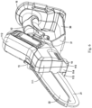
Fig. 6 is a perspective view of the hand-held electric tool shown inFig. 1 taken from the top side and the front side. -
- 100 Hand-held electric tool
- 10 Housing
- 11 Main body section
- 11a Bottom wall of main body section
- 11b Chip removal hole
- 111 First section of main body section
- 112 Second section of main body section
- 113 First housing portion of main body section
- 114 Second housing portion of main body section
- 115 Third housing portion of main body section
- 113a Protective wall
- 113b Guide wall
- 12 Grip section
- 13 First rest block
- 131 Rear end face of first rest block
- 14 Second rest block
- 141 Front end face of second rest block
- 15 Guide member
- 151 First guide wall
- 152 Second guide wall
- 16 Battery engagement section
- 17 Transmission member
- 20 Operating component
- 21 Saw chain
- 211 Bottom section of saw chain
- 212 Top section of saw chain
- 213 Front connecting section of saw chain
- 215 Rear connecting section of saw chain
- 214 Support plate
- 22 Protective cover
- 30 Protective portion
- 31 Baffle
- 32 Transition section
- 33 Protective portion cross member
- Specific embodiments of the present invention are now described in detail with reference to the drawings. The embodiments described here are merely preferred embodiments according to the present invention; those skilled in the art will be able to think of other ways of implementing the present invention based on these preferred embodiments, and these other ways likewise fall within the scope of the present invention.
-
Fig. 1-Fig. 6 are preferred embodiments of a hand-held electric tool according to the present invention, which may be, for example, a hand-held trimming device or a hand-held cutting device. First of all, it must be explained that directional and positional terms in the present invention should be understood to mean relative directions and positions, not absolute directions and positions. The directional terms and positional terms used in the present invention are explainable with reference to the exemplary structures shown inFig. 1-Fig. 6 . For example, as used in the present invention, "front side" and "forwards" refer to the direction that extends in direction D1 and, when the user correctly holds the hand-held electric tool, is away from the user (that is, the direction pointing to the left as shown inFig. 1 ); "rear side" and "backwards" refer to the direction that extends in direction D1 and, when the user correctly holds the hand-held electric tool, faces the user (that is, the direction pointing to the right as shown inFig. 1 ); terms like "top side" and "above" refer to the upward position and direction in direction D2 as shown inFig. 1 ; terms like "bottom side" and "below" refer to the downward position and direction in direction D2 as shown inFig. 1 ; the width of a component refers to the size of the component in direction D3; and the length of a component refers to the size of the component in direction D1. In addition, the terms "first" and "second" as used in the present invention are only intended to distinguish between names, rather than implying any order of precedence, wherein, for example, the presence of a second rest block does not necessarily mean that a first rest block exists. - Referring first to
Fig. 1 , a hand-heldelectric tool 100 of the present invention comprises ahousing 10 and anoperating component 20. Thehousing 10 and the components located therein constitute the main structure of the hand-heldelectric tool 100. In some embodiments, thehousing 10 may have amain body section 11 and agrip section 12 extending backwards from themain body section 11, as well as abattery engagement section 16 located at the rear end of thegrip section 12 and extending perpendicular to thegrip section 12. Themain body section 11 may further comprise afirst section 111 and asecond section 112 that are adjacent to each other, wherein thesecond section 112 is configured to accommodate themotor section 15 of the electric machine, for example. The direction of extension of thefirst section 111 forms an angle between 100-160 degrees, preferably between 100-150 degrees, and more preferably between 140-150 degrees with the direction of extension of thesecond section 112. Referring toFig. 3 , the housing of themain body section 11 may comprise afirst housing portion 113, asecond housing portion 114, and athird housing portion 115 arranged sequentially in a third direction D3. - The front end of the
main body section 11 is provided with a mounting interface, and the operatingcomponent 20 may be mounted at the mounting interface of thehousing 10 and protrude forwards from thehousing 10. In some embodiments, thegrip section 12 may extend backwards and downwards from themain body section 11, such that an obtuse angle is formed between the direction of extension of thegrip section 12 and the direction of extension of the operatingcomponent 20. A battery can be slid in a direction of extension parallel to thebattery engagement section 16 to the position where it engages thebattery engagement section 16. - The operating
component 20 is used for cutting and trimming objects to be worked, such as woods and branches of trees. Referring toFig. 2 , in some embodiments, the operatingcomponent 20 comprises, for example, asaw chain 21 supported by asupport plate 214, thesaw chain 21 being rotatable around thesupport plate 214 within a plane defined by the first direction D1 and the second direction D2 to cut an object. Preferably, the top of thesaw chain 21 is provided with aprotective cover 22, theprotective cover 22 being removable from thehousing 10 or pivotally openable relative to thehousing 10. During the operation, when thesaw chain 21 acts on an object to be worked, some chips will be generated and, as thesaw chain 21 rotates, will be driven into thehousing 10, and achip removal hole 11b for removing chips is formed in thebottom wall 11a of themain body section 11 of thehousing 10, thechip removal hole 11b being shown in detail inFig. 3-Fig. 4B . - Again referring to
Fig. 2 , in some embodiments, thesaw chain 21 comprises abottom section 211, atop section 212, as well as afront connecting section 213 and arear connecting section 215 that are connected therebetween (as shown inFig. 4A andFig. 4B , therear connecting section 215 may be located within the housing 10), wherein, during the operation, thebottom section 211 moves backwards and thetop section 212 moves forwards. Therear connecting section 215 of thesaw chain 21 rotates around a transmission member 17 (seeFig. 4A andFig. 4B ) to be driven by thetransmission member 17, thetransmission member 17 can be connected to the output shaft of the motor. Thechip removal hole 11b is positioned just downstream of the movement direction of thebottom section 211 of thesaw chain 21 to allow the removal of chips, thus preventing the accumulation of chips in thehousing 10. - Referring to
Fig. 3 , the bottom of thehousing 10 is substantially closed, on which only onechip removal hole 11b is provided, thechip removal hole 11b being preferably located at the rearmost end of thebottom wall 11a of themain body section 11. In some embodiments, the bottom walls of thesecond housing portion 114 and thethird housing portion 115 are complete, and only the rear end of the bottom wall of thefirst housing portion 113 is provided with an opening for the formation of achip removal hole 11b. In some embodiments, thechip removal hole 11b may have a small opening area, wherein the length of thechip removal hole 11b may be 1/8-1/4 that of themain body section 11, for example, and the length of thechip removal hole 11b may be 1/5 that of themain body section 11, for example; the width of thechip removal hole 11b may be 1/4-1/2 that of themain body section 11, wherein the width of thechip removal hole 11b may be 1/3 that of themain body section 11, for example. In some embodiments, thechip removal hole 11b has a regular shape, being, for example, a substantially circular hole or, as shown inFig. 3 , a substantially square hole. The substantially closed bottom structure of the hand-heldelectric tool 100 allows the removal of chips while preventing a user's hand from being inadvertently extended into thehousing 10 and contacting the operatingcomponent 20 rotating at a high speed. For example, in some embodiments, the rotary speed of thesaw chain 21 may be as high as 3-8 m/s, preferably 4-8 m/s and more preferably 6 m/s. - Possible orientations of the chip removal hole are shown in
Fig. 4A andFig. 4B . Referring toFig. 4A , the direction of removal of chips is indicated by an arrow, which has a forward component and a downward component, so it is clear that thechip removal hole 11b is oriented downwards and forwards. Preferably, thefirst housing portion 113 has a forwardly and downwardly extendinginner wall 113b located behind thechip removal hole 11b, theinner wall 113b being usable as a guide wall to guide chips forwards and downwards. Thebottom wall 113a of thefirst housing portion 113 forms a protective wall to prevent a user's hand from being extended upwards into the housing. - The structure shown in
Fig. 4B is substantially the same as that shown inFig. 4A , except that aguide member 15 is further provided inFig. 4B to guide chips backwards and downwards until they are removed through thechip removal hole 11b. InFig. 4B , the direction of removal of chips is also indicated by arrows, with the endmost arrow portion having a backward component and a downward component, so it is clear that thechip removal hole 11b is oriented downwards and backwards. Optionally, theguide member 15 comprises afirst guide wall 151 and asecond guide wall 152 that is located below thefirst guide wall 151 and has a guide direction different from that of thefirst guide wall 151, thesecond guide wall 152 extending backwards and downwards. More preferably, thefirst guide wall 151 and therear connecting section 215 of thesaw chain 21 face each other and are shaped to fit each other, so that thefirst guide wall 151 is a curved wall, while thesecond guide wall 152 may be a straight wall. - The arrangements and orientations of the two chip removal holes shown in
Fig. 4A andFig. 4B are conducive to the centralised removal of chips, particularly suitable for small hand-held electric tools. - To prevent chips removed from the
chip removal hole 11b from continuing to move due to inertia and falling onto the user's hand, the hand-heldelectric tool 100 of the present application is provided with aprotective portion 30 that extends downwards at least partially behind the chip removal hole 1 1b (that is, at the bottom end at the position where themain body section 11 joins the grip section 12), and theprotective portion 30 can separate thechip removal hole 11b from thegrip section 12 for the user to grasp, so that chips removed through thechip removal hole 11b do not contact the user's hand. Theprotective portion 30 comprises, for example, abaffle 31 directly connected to the rear side of thechip removal hole 11b. Preferably, thebaffle 31 may extend downwards and forwards to enhance the effect of chip blockage. - The
protective portion 30 may be just a downwardly extending baffle as described above, but in some embodiments, with continued reference toFig. 1-Fig. 3 , theprotective portion 30 may extend as a whole towards thebattery engagement section 16. It should be noted that the backward extension of theprotective portion 30 as a whole does not mean that each portion thereof extends backwards, wherein, for example, the frontmost portion of theprotective portion 30, which serves as thebaffle 31, may partially extend forwards. Theprotective portion 30, thegrip section 12, and thebattery engagement section 16 may jointly define a ring shape that closes on the plane defined by direction D1 and direction D2, and a user's hand can extend into the ring. More specifically, theprotective portion 30 further comprises a protectiveportion cross member 33 that is parallel to the direction of extension of thegrip section 12 and atransition section 32 connected between the protectiveportion cross member 33 and thebaffle 31. The protectiveportion cross member 33 constitutes the main body of theprotective portion 30, wherein, for example, the length of the protectiveportion cross member 33 may be greater than 1/2 or 2/3 of the overall length of the protective portion. Preferably, both thebaffle 31 and the protectiveportion cross member 33 can have a specific shape or direction of extension (for example, thebaffle 31 extends downwards and forwards, and the protectiveportion cross member 33 is parallel to the direction of extension of the grip section 12), and there may be no limitations on the direction of extension of thetransition section 32, as long as the protectiveportion cross member 33 can be connected to thebaffle 31. Setting the protectiveportion cross member 33 to be parallel to the direction of extension of thegrip section 12 can increase the space for accommodating the user's hand, thus bringing greater comfortableness to the user. - Although in the embodiments shown in
Fig. 1 - Fig. 6 , theprotective portion 30 extends from the position of engagement between themain body section 11 and thegrip section 12 to the bottom end of thebattery engagement section 16, in another embodiment not shown, there may be a gap between theprotective portion 30 and thebattery engagement section 16, which means that the area for accommodating the user's hand may be an unclosed structure. In other words, theprotective portion 30, instead of being used to form a closed ring shape, may also open to a certain extent, which means that the protectiveportion cross member 33 may form a cantilever structure. - In order to more preferably produce the protection effect of the
protective portion 30, thebaffle 31 may be set to have a large width, for example, by making the width of thebaffle 31 greater than that of thehousing 10. More preferably, theprotective portion 30 may also be arranged to have a large width as a whole. A comparison between the width of theprotective portion 30 and that of thehousing 10 is shown inFig. 5 , and as is clear fromFig. 5 , the width of theprotective portion 30 is greater than that of thehousing 10, especially that of thegrip section 12, wherein, for example, the width of theprotective portion 30 may be 2-3 times that of thegrip section 12. With this arrangement, the user's hand is effectively protected within a space defined by theprotective portion 30, thegrip section 12, and thebattery engagement section 16, while chips and other impurities that may be generated during operation are difficult to enter the space. Although not shown in the drawings, preferably theprotective portion 30 may have an increased width at thebaffle 31, and the width of thebaffle 31 may be greater than that of the protectiveportion cross member 33 and that of thetransition section 32. - The
housing 10 of the hand-heldelectric tool 100 is further provided with structures that can improve operational stability and safety. For example, referring toFig. 1-2 andFig. 5-6 , the top side of themain body section 11 is provided with afirst rest block 13, thefirst rest block 13 being configured to allow the user's hand to rest against therear end face 131 of thefirst rest block 13. For example, a user can extend his/her index finger, middle finger, ring finger, and little finger into the annular space defined by theprotective portion 30, thegrip section 12, and thebattery engagement section 16, while resting his/her thumb against therear end face 131 of thefirst rest block 13; alternatively, the user can rest his/her index finger against the rear end face of thefirst rest block 13. Preferably, thefirst rest block 13 is located at least partially in thefirst section 111 of themain body section 11, and more preferably, thefirst rest block 13 is located substantially in thefirst section 111. - Preferably, since the
first rest block 13 only needs to abut and contact the user's fingers, thefirst rest block 13 does not need to have a large width, wherein, as shown inFig. 5 , for example, the width of therear end face 131 of thefirst rest block 13 may be 1/5-1/3 that of themain body section 11. Preferably, thefirst rest block 13 is configured with an L-shaped top surface, and the portion of the L-shaped structure extending in the third direction D3 serves as a portion that abuts and contacts the user's fingers; the portion of the L-shaped structure extending in the first direction D1 serves as a reinforcing rib. Thefirst rest block 13, besides improving operational stability, prevents the user's fingers from crossing the front end of thehousing 10 and contacting an operating component. Moreover, the L-shapedfirst rest block 13 does not prevent theprotective cover 22 from springing open. - Similarly, referring to
Fig. 1-3 , asecond rest block 141 is provided at the frontmost position on the bottom side of themain body section 11, and thesecond rest block 141 is configured such that itsfront end face 141 abuts the object to be worked during use. Since an object to be worked is usually large, increasing the area of contact with the object to be worked can improve the stability of the engagement, so preferably thesecond rest block 141 extends over the almost complete width of themain body section 11, which means that the width of thesecond rest block 141 is substantially equal to that of themain body section 11. In addition, the length of thesecond rest block 141 is most preferably 1/5-1/3 that of themain body section 11, wherein it is comprehensible that if thesecond rest block 141 has a small length, it easily breaks due to insufficiency of stiffness, while if thesecond rest block 141 is too long, thehousing 10 of the hand-heldelectric tool 100 is heavy. - According to the present invention, the bottom of the main body of a hand-held electric tool is provided with a bottom wall, and a chip removal hole is provided in the bottom wall, which means that the bottom of the hand-held electric tool is substantially closed, so such a bottom arrangement allows the removal of chips while preventing a user's hand from being inadvertently extended into the housing and contacting a component operating at a high speed. The rear side of the chip removal hole of the hand-held electric tool is provided with a protective portion, so that chips removed through the chip removal hole are blocked by the protective portion, without reaching the grip section, which offers considerable advantages in terms of safety and hygiene. On the other hand, the present invention provides preferred settings of the dimensions of various components and structures, making the hand-held electric tool safer and more comfortable. A hand-held electric tool of the present invention is further provided with a first rest block located at the top for a user's fingers to rest, and a second rest block located at the bottom for the object to be worked to rest, wherein these rest blocks can improve operational stability, and the first rest block can also prevent the user's fingers from crossing the front end of the housing and contacting an operating component.
- The above description of various embodiments of the present invention is provided to a person skilled in the art for descriptive purposes. The present invention is not intended to be exclusive or limited to a single disclosed embodiment. Based on the above, a person skilled in the art as taught above will understand various substitutes for and variants of the present invention. Thus, although some alternative embodiments have been described specifically, those skilled in the art will understand or develop with relative ease other embodiments. The present invention is intended to include all substitutes for, alterations to, and variants of the present invention described herein, as well as other embodiments falling within the spirit and scope of the present invention described above.
Claims (15)
- Hand-held electric tool, characterized in that the hand-held electric tool (100) comprises:a housing (10) having a main body section (11) and a grip section (12) extending towards the rear side from the main body section, wherein the front end of the main body section is provided with a mounting interface;an operating component (20) mounted at the mounting interface of the housing and protruding from the housing, whereina chip removal hole (11b) is formed in a bottom wall (11a) of the main body section (11) of the housing, and a protective portion that extends downwards at least partially is provided at the bottom end at a position where the main body section joins the grip section.
- Hand-held electric tool according to Claim 1, characterized in that the chip removal hole (11b) is oriented forwards and downwards, preferably with the inner wall (113b) of the housing, which is located behind the chip removal hole, extending forwards and downwards.
- Hand-held electric tool according to Claim 1, characterized in that the chip removal hole (11b) is oriented backwards and downwards, and the main body section comprises a guide member (15) located near the chip removal hole (11b) to guide the removal of chips backwards and downwards from the main body section, wherein, preferably, the guide member comprises a first guide wall (151) and a second guide wall (152) that is located below the first guide wall and has a guide direction different from that of the first guide wall, the second guide wall extending backwards and downwards.
- Hand-held electric tool according to Claim 3, characterized in that the operating component (20) comprises a saw chain (21) that rotates on its plane of extension, the first guide wall (151) facing and being shaped to fit a portion (215) of the saw chain.
- Hand-held electric tool according to any one of Claims 1-4, characterized in that the protective portion comprises a downwardly and forwardly extending baffle (31) located at its frontmost portion.
- Hand-held electric tool according to Claim 5, characterized in that the protective portion (30) further comprises a protective portion cross member (33) extending backwards from the baffle, defining a space for accommodating a user's hand between the protective portion (30) and the grip section (12).
- Hand-held electric tool according to Claim 6, characterized in that the housing (10) further comprises a battery engagement section (16) located at the rear end of the grip section (12) and extending substantially perpendicular to the grip section, preferably with the protective portion (30) extending to join the lower end of the battery engagement section (16).
- Hand-held electric tool according to Claim 6 or 7, characterized in that the width of the baffle (31) is greater than that of the housing (10), wherein preferably the overall width of the protective portion (30) is greater than the width of the grip section (12), and preferably the baffle of the protective portion is wider than other parts.
- Hand-held electric tool according to any one of Claims 6-8, characterized in that the grip section (12) extends backwards and downwards from the main body section, preferably with the protective portion cross member (33) being substantially parallel to the direction of extension of the grip section.
- Hand-held electric tool according to any one of Claims 1-9, characterized in that the chip removal hole (11b) is adjacent to the front surface of the protective portion (3), wherein preferably the chip removal hole has a length that is 1/8-1/4 that of the main body section (11), preferably the chip removal hole has a width that is 1/4-1/2 that of the main body section, and preferably the chip removal hole is a substantially circular hole or a substantially square hole.
- Hand-held electric tool according to any one of Claims 1-10, characterized in that the operating component (20) comprises a saw chain (21) that rotates on its plane of extension, the saw chain comprising a bottom section (211), a top section (212), as well as a front connecting section (213) and a rear connecting section (215) that are connected therebetween, wherein the bottom section (211) of the saw chain moves backwards during the operation.
- Hand-held electric tool according to any one of Claims 1-11, characterized in that the top side of the main body section (11) is provided with a first rest block (13), which is configured to allow a user's hand to rest against a rear end face of the first rest block, wherein, preferably, the width of the rear end face (131) of the first rest block is 1/5-1/3 that of the main body section, and preferably, a top surface of the first rest block is configured as an L-shaped structure.
- Hand-held electric tool according to any one of Claims 1-12, characterized in that a second rest block (14) is arranged at the frontmost position on the bottom side of the main body section (11), and the second rest block is configured such that its front end face (141) abuts an object to be worked during use, wherein, preferably, the second rest block extends over almost the entire width of the main body section, and preferably, the length of the second rest block is 1/5-1/3 that of the main body section.
- Hand-held electric tool according to any one of Claims 1-13, characterized in that the main body section (11) comprises a first section (111) and a second section (112) that are adjacent to each other, wherein the direction of extension of the first section (111) forms an angle between 100-160 degrees, preferably between 100-150 degrees, and more preferably between 140-150 degrees with the direction of extension of the second section (112), the second section (112) being specifically a motor section.
- Hand-held electric tool according to Claim 14, characterized in that the first rest block (13) is located at least partially in the first section (111), preferably the first rest block (13) being located substantially in the first section (112).
Applications Claiming Priority (1)
| Application Number | Priority Date | Filing Date | Title |
|---|---|---|---|
| CN202210383385.9A CN116944586A (en) | 2022-04-12 | 2022-04-12 | Hand-held electric tool |
Publications (3)
| Publication Number | Publication Date |
|---|---|
| EP4260970A1 true EP4260970A1 (en) | 2023-10-18 |
| EP4260970B1 EP4260970B1 (en) | 2025-12-03 |
| EP4260970C0 EP4260970C0 (en) | 2025-12-03 |
Family
ID=86006743
Family Applications (1)
| Application Number | Title | Priority Date | Filing Date |
|---|---|---|---|
| EP23167381.5A Active EP4260970B1 (en) | 2022-04-12 | 2023-04-11 | Hand-held electric tool |
Country Status (4)
| Country | Link |
|---|---|
| US (2) | US12390869B2 (en) |
| EP (1) | EP4260970B1 (en) |
| CN (1) | CN116944586A (en) |
| AU (1) | AU2023202270A1 (en) |
Families Citing this family (18)
| Publication number | Priority date | Publication date | Assignee | Title |
|---|---|---|---|---|
| US12539639B2 (en) * | 2022-04-18 | 2026-02-03 | Black & Decker Inc. | Chain saw |
| JP7825516B2 (en) * | 2022-06-16 | 2026-03-06 | 株式会社マキタ | cutting tools |
| JP1735659S (en) * | 2022-07-06 | 2023-01-30 | Portable electric chainsaw body | |
| US12629861B2 (en) * | 2022-08-18 | 2026-05-19 | Nanjing Chervon Industry Co., Ltd. | Handheld cutting tool |
| USD1049811S1 (en) * | 2022-09-30 | 2024-11-05 | Greenworks (Jiangsu) Co., Ltd | Chain saw |
| USD1033190S1 (en) * | 2023-06-12 | 2024-07-02 | Yongkangshi Yanxu Tools Co., Ltd. | Chainsaw |
| USD1074365S1 (en) * | 2023-08-03 | 2025-05-13 | Zhenwei Hu | Chainsaw |
| USD1074366S1 (en) * | 2023-08-14 | 2025-05-13 | Hanqiang Shen | Chain saw |
| USD1096350S1 (en) * | 2023-08-15 | 2025-10-07 | Andreas Stihl Ag & Co. Kg | Chainsaw |
| USD1074367S1 (en) * | 2023-08-15 | 2025-05-13 | Hanqiang Shen | Chain saw |
| USD1097745S1 (en) * | 2023-10-13 | 2025-10-14 | Ziwei LI | Chain saw |
| USD1091271S1 (en) * | 2023-10-13 | 2025-09-02 | Ziwei LI | Chain saw |
| USD1037814S1 (en) * | 2023-10-19 | 2024-08-06 | Minli Liao | Chainsaw |
| USD1069531S1 (en) * | 2024-01-03 | 2025-04-08 | Ningbo Vertak Mechanical & Electronic Co., Ltd. | Cordless mini chainsaw |
| USD1081312S1 (en) * | 2024-02-29 | 2025-07-01 | Andreas Stihl Ag & Co. Kg | Chainsaw |
| JP2026002247A (en) * | 2024-06-21 | 2026-01-08 | 株式会社やまびこ | chainsaw |
| USD1067741S1 (en) * | 2024-10-14 | 2025-03-25 | Fulong Hu | Hand chain saw |
| USD1067742S1 (en) * | 2024-11-11 | 2025-03-25 | Blooming Forest (Hk) Limited | Electric chain saw |
Citations (5)
| Publication number | Priority date | Publication date | Assignee | Title |
|---|---|---|---|---|
| US20040098869A1 (en) * | 2002-11-19 | 2004-05-27 | Homelite Technologies, Ltd. | Battery operated chain saw |
| US20110005088A1 (en) * | 2007-12-20 | 2011-01-13 | Pellenc (Societe Anonyme) | Portable electric chainsaw |
| AU2011221378A1 (en) * | 2003-07-14 | 2011-09-29 | Black & Decker, Inc. | Vegetation pruning device |
| US20180133818A1 (en) * | 2016-11-14 | 2018-05-17 | Andreas Stihl Ag & Co. Kg | Handheld portable cutting apparatus having a cutter unit |
| WO2022048532A1 (en) * | 2020-09-02 | 2022-03-10 | 南京德朔实业有限公司 | Chainsaw |
Family Cites Families (92)
| Publication number | Priority date | Publication date | Assignee | Title |
|---|---|---|---|---|
| US2990858A (en) | 1959-05-27 | 1961-07-04 | Anderson G Ledger | Portable air driven chain saw |
| US4193193A (en) * | 1978-08-09 | 1980-03-18 | Adolph Holzworth | Guard for chain saw |
| CA1106264A (en) | 1979-04-20 | 1981-08-04 | Norman C. Bricker | Chain saw bar tightener |
| EP0205620B1 (en) | 1984-12-05 | 1990-12-19 | Fuji Blade Co. Ltd. | Chain saw |
| US4887357A (en) | 1986-11-24 | 1989-12-19 | Pro Power Corporation | Articulated endless-band saw blade and support therefor |
| US4819335A (en) | 1987-09-09 | 1989-04-11 | Pro Power Corporation | Detachable blade assembly for a chain saw |
| US4841641A (en) | 1988-02-16 | 1989-06-27 | Laidlaw Gerry A | Chain saw safety structure |
| US5491899A (en) | 1992-06-25 | 1996-02-20 | Stihl Andreas | Tensioning arrangement for a saw chain |
| DE4436543C2 (en) | 1993-11-12 | 2002-07-11 | Stihl Maschf Andreas | Tensioning device for a chain saw of a motor chain saw running over a saw blade |
| US5685080A (en) * | 1996-04-22 | 1997-11-11 | Makita Corporation | Battery powered chain saw |
| USD389026S (en) | 1996-04-23 | 1998-01-13 | Makita Corporation | Portable electric chain saw |
| DE19931250A1 (en) | 1999-07-07 | 2001-01-11 | Bosch Gmbh Robert | chainsaw |
| USD445657S1 (en) * | 2000-11-29 | 2001-07-31 | Jenn Feng Industrial Co., Ltd. | Chain saw |
| JP2002210705A (en) | 2001-01-19 | 2002-07-30 | Ryobi Ltd | Chain saw |
| TW503810U (en) | 2001-08-02 | 2002-09-21 | Jenn Feng Ind Co Ltd | Tool-free adjustment structure for chain saw |
| DE20118322U1 (en) | 2001-11-12 | 2002-01-17 | Jenn Feng Industrial Co., Ltd., Ping Chang, Taoyuan | Device for adjusting the tension of a chainsaw |
| FI20021379L (en) | 2002-07-12 | 2004-01-13 | Plustech Oy | Sawing equipment and its safety system in case of a broken saw chain |
| SE0300611D0 (en) | 2003-03-06 | 2003-03-06 | Electrolux Ab | Chain saw tensioning device |
| JP4584143B2 (en) | 2003-05-20 | 2010-11-17 | ハスクバーナ・ゼノア株式会社 | Auto chain tensioner |
| GB2404613A (en) | 2003-07-14 | 2005-02-09 | David Jarman | A vegetation pruning device |
| US7287330B1 (en) | 2004-09-29 | 2007-10-30 | G&R Equipment, Llc | Chain saw automatic tensioner |
| US7107689B2 (en) | 2004-10-08 | 2006-09-19 | Husqvarna Outdoor Products Inc. | Bar knob with integrated lock |
| DE202005001674U1 (en) | 2005-02-03 | 2005-04-14 | Kmk Kunststoff- Und Montagetechnik Gmbh | Hand-guided garden implement with an electromotive drive system with multiphase motor |
| US7155832B2 (en) | 2005-03-01 | 2007-01-02 | Husqvarna Outdoor Products Inc. | Chain saw with tool-less chain tensioner and guide bar lock |
| US7284333B2 (en) * | 2005-05-06 | 2007-10-23 | Julie Lawler | Chainsaw kickback protection device |
| GB0515970D0 (en) | 2005-08-03 | 2005-09-07 | Bosch Gmbh Robert | Chain saw |
| USD547630S1 (en) * | 2005-09-06 | 2007-07-31 | Desa Ip, Llc | Chain saw |
| US7743513B1 (en) | 2006-10-31 | 2010-06-29 | Mtd Products Inc | Chainsaw tensioning device |
| US8136254B2 (en) | 2007-02-06 | 2012-03-20 | Mtd Products Inc | Split power tool with extension |
| FR2913076B1 (en) | 2007-02-26 | 2010-10-22 | Pellenc Sa | CLAMPING DEVICE WITH RETRACTABLE SHAFT ARM AND APPARATUS INCLUDING THE SAME |
| FR2912949B1 (en) | 2007-02-26 | 2009-04-24 | Pellenc Sa | CHAIN SAW HAVING A DEVICE FOR ADJUSTING THE VOLTAGE OF THE CUTTING CHAIN |
| USD603672S1 (en) * | 2007-04-24 | 2009-11-10 | Black & Decker Inc. | Cordless lopper |
| USD560456S1 (en) * | 2007-06-04 | 2008-01-29 | Desa Ip, Llc | Chain saw |
| FR2920683B1 (en) | 2007-09-06 | 2010-02-12 | Pellenc Sa | MULTIPURPOSE ELECTROPORTATIVE DEVICES. |
| US20090241353A1 (en) | 2008-04-01 | 2009-10-01 | Scott William Ericson | Toolless Apparatus for Guide Bar for Chain Saw |
| CA2729341C (en) | 2008-06-24 | 2016-06-07 | Mtd Products Inc | Torque-limited chain tensioning for power tools |
| JP5486214B2 (en) | 2009-05-20 | 2014-05-07 | 株式会社マキタ | Power tools |
| JP5314496B2 (en) | 2009-05-20 | 2013-10-16 | 株式会社マキタ | Chainsaw |
| JP5530186B2 (en) * | 2010-01-04 | 2014-06-25 | 株式会社マキタ | Hand-held power tool |
| USD631314S1 (en) | 2010-03-22 | 2011-01-25 | Black & Decker Inc. | Hand-held reciprocating saw |
| US20120174416A1 (en) | 2011-01-07 | 2012-07-12 | Ci, Llc | Electric pruning device |
| CN102101084B (en) | 2011-01-12 | 2013-03-20 | 奉化市威优特电器有限公司 | Handheld electric spray gun |
| ITPD20110060A1 (en) | 2011-02-28 | 2012-08-29 | Zanon S R L | CHAINSAWS, PARTICULARLY FOR PRUNING TREES AND SHRUBS |
| WO2012126501A1 (en) | 2011-03-18 | 2012-09-27 | Husqvarna Ab | Chainsaw with guide bar clamping and chain tensioning assembly |
| WO2012144942A1 (en) | 2011-04-21 | 2012-10-26 | Husqvarna Ab | A clamping assembly for a chainsaw |
| US9132568B2 (en) | 2011-10-11 | 2015-09-15 | Echo, Inc. | Chainsaw with cutting chain tensioner |
| JP5962082B2 (en) * | 2012-03-14 | 2016-08-03 | 日立工機株式会社 | Chainsaw |
| DE102012010963A1 (en) | 2012-05-31 | 2013-12-05 | Andreas Stihl Ag & Co. Kg | Implement with sprocket cover |
| US20150135542A1 (en) | 2012-06-06 | 2015-05-21 | Husqvarna Ab | Feedback system for bar clamping |
| JP6032400B2 (en) | 2012-08-15 | 2016-11-30 | 日立工機株式会社 | Chainsaw |
| CN202857378U (en) | 2012-10-26 | 2013-04-10 | 浙江三锋实业股份有限公司 | Chain saw |
| JP2014148117A (en) | 2013-02-01 | 2014-08-21 | Makita Corp | Chain saw |
| DE102013003850A1 (en) | 2013-03-06 | 2014-09-25 | Andreas Stihl Ag & Co. Kg | Hand-held implement with a tensioning device for a chain |
| WO2014142722A1 (en) | 2013-03-15 | 2014-09-18 | Husqvarna Ab | Chainsaw with self-locking knob assembly |
| JP6026943B2 (en) | 2013-03-29 | 2016-11-16 | 株式会社マキタ | Chainsaw guide bar fastening device |
| US9669563B2 (en) | 2015-05-26 | 2017-06-06 | Jenn Feng New Energy Co., Ltd. | Chain saw with tool-free chain tension adjustment mechanism |
| DE202015004337U1 (en) | 2015-06-18 | 2015-10-05 | Jenn Feng New Energy Co., Ltd. | Chainsaw with chain tension adjustment mechanism |
| CN204975540U (en) | 2015-07-27 | 2016-01-20 | 上虞市冠业电器有限公司 | Electric chain saw of chain integration locking |
| WO2017028202A1 (en) | 2015-08-18 | 2017-02-23 | Black & Decker Inc. | Low profile chainsaw |
| US20170239835A1 (en) * | 2016-02-23 | 2017-08-24 | Milwaukee Electric Tool Corporation | Chainsaw |
| EP3229350B1 (en) | 2016-04-08 | 2021-06-23 | Black & Decker Inc. | Brushless motor for a power tool |
| US20180084731A1 (en) | 2016-09-29 | 2018-03-29 | Mtd Products Inc | Split power tool |
| US10537983B2 (en) | 2016-10-17 | 2020-01-21 | Black & Decker, Inc. | Modular power tool |
| US10434682B2 (en) | 2016-11-22 | 2019-10-08 | Raffaele A. Bonomi | Quick chain tensioning system |
| US10603728B2 (en) | 2017-01-12 | 2020-03-31 | Milwaukee Electric Tool Corporation | Reciprocating saw |
| EP3385045B1 (en) | 2017-04-04 | 2022-01-26 | Andreas Stihl AG & Co. KG | Power chain saw |
| CN109877917A (en) | 2017-12-06 | 2019-06-14 | 莱克电气股份有限公司 | chainsaw |
| AU2018408707A1 (en) | 2018-02-14 | 2020-08-06 | Techtronic Cordless Gp | Outer rotor motor |
| US11343973B2 (en) | 2018-05-23 | 2022-05-31 | Milwaukee Electric Tool Corporation | Pole saw |
| CN110560782B (en) | 2018-06-05 | 2021-11-19 | 南京德朔实业有限公司 | Chain saw |
| USD917247S1 (en) | 2018-12-21 | 2021-04-27 | Andreas Stihl Ag & Co. Kg | Cordless shrub shear |
| JP7202899B2 (en) | 2019-01-15 | 2023-01-12 | 株式会社やまびこ | electric work machine |
| JP7261633B2 (en) | 2019-03-26 | 2023-04-20 | 株式会社やまびこ | electric work machine |
| JP7228479B2 (en) | 2019-06-20 | 2023-02-24 | 株式会社やまびこ | electric work machine |
| DE102019121221B4 (en) | 2019-08-06 | 2023-08-03 | Jörg Hillmann | Chain tensioning device of a chainsaw |
| EP3792008B1 (en) | 2019-09-12 | 2024-05-01 | Andreas Stihl AG & Co. KG | Hand-guided appliance with a tool |
| CN211030357U (en) | 2019-09-20 | 2020-07-17 | 吴贵敏 | Rechargeable outer rotor motor chain saw |
| USD934042S1 (en) | 2019-10-09 | 2021-10-26 | Würth International Ag | Caulking gun |
| US11524423B2 (en) | 2019-10-18 | 2022-12-13 | Globe (Jiangsu) Co., Ltd | Chain saw |
| CN211362619U (en) | 2019-10-18 | 2020-08-28 | 格力博(江苏)股份有限公司 | a chain saw |
| EP4670937A3 (en) | 2019-11-25 | 2026-07-29 | Milwaukee Electric Tool Corporation | Powered handheld cutting tool |
| CN110788938B (en) * | 2019-11-29 | 2025-12-16 | 格力博(江苏)股份有限公司 | Chain saw |
| CN211362622U (en) | 2019-11-29 | 2020-08-28 | 格力博(江苏)股份有限公司 | Chain saw |
| CN212287976U (en) | 2020-03-02 | 2021-01-05 | 浙江锐木园林机械有限公司 | Chain tool of formula double-screw bolt cut straightly |
| CN212368051U (en) | 2020-04-22 | 2021-01-19 | 珠峰动力机械(宁德)有限公司 | Electric chain saw with chain adjusting mechanism |
| CN213320571U (en) | 2020-07-01 | 2021-06-01 | 东莞市嘉航实业有限公司 | A one-hand saw with oil can |
| CN213044275U (en) | 2020-09-24 | 2021-04-27 | 厉洪武 | Lithium electric saw with automatic oil pumping and filling device |
| USD932268S1 (en) | 2020-11-04 | 2021-10-05 | Shenghui Liao | Pruning saw |
| CN112339021A (en) | 2020-11-11 | 2021-02-09 | 永康市兴虎动力机械有限公司 | Hand chain saw |
| USD959945S1 (en) | 2021-06-22 | 2022-08-09 | Jimin Lin | Mini chainsaw |
| USD957225S1 (en) | 2021-07-04 | 2022-07-12 | Hefei Qiongzhi Network Technology Co., Ltd. | Mini chainsaw |
| USD1049811S1 (en) * | 2022-09-30 | 2024-11-05 | Greenworks (Jiangsu) Co., Ltd | Chain saw |
-
2022
- 2022-04-12 CN CN202210383385.9A patent/CN116944586A/en active Pending
-
2023
- 2023-04-11 EP EP23167381.5A patent/EP4260970B1/en active Active
- 2023-04-12 US US18/133,776 patent/US12390869B2/en active Active
- 2023-04-12 AU AU2023202270A patent/AU2023202270A1/en active Pending
-
2025
- 2025-07-23 US US19/278,423 patent/US20250345870A1/en active Pending
Patent Citations (6)
| Publication number | Priority date | Publication date | Assignee | Title |
|---|---|---|---|---|
| US20040098869A1 (en) * | 2002-11-19 | 2004-05-27 | Homelite Technologies, Ltd. | Battery operated chain saw |
| AU2011221378A1 (en) * | 2003-07-14 | 2011-09-29 | Black & Decker, Inc. | Vegetation pruning device |
| US20110005088A1 (en) * | 2007-12-20 | 2011-01-13 | Pellenc (Societe Anonyme) | Portable electric chainsaw |
| US20180133818A1 (en) * | 2016-11-14 | 2018-05-17 | Andreas Stihl Ag & Co. Kg | Handheld portable cutting apparatus having a cutter unit |
| WO2022048532A1 (en) * | 2020-09-02 | 2022-03-10 | 南京德朔实业有限公司 | Chainsaw |
| EP4186665A1 (en) * | 2020-09-02 | 2023-05-31 | Nanjing Chervon Industry Co., Ltd. | Chainsaw |
Also Published As
| Publication number | Publication date |
|---|---|
| US12390869B2 (en) | 2025-08-19 |
| CN116944586A (en) | 2023-10-27 |
| US20230321738A1 (en) | 2023-10-12 |
| AU2023202270A1 (en) | 2023-10-26 |
| EP4260970B1 (en) | 2025-12-03 |
| EP4260970C0 (en) | 2025-12-03 |
| US20250345870A1 (en) | 2025-11-13 |
Similar Documents
| Publication | Publication Date | Title |
|---|---|---|
| EP4260970B1 (en) | Hand-held electric tool | |
| JP7249228B2 (en) | electric work machine | |
| RU2469840C2 (en) | Cutting tools | |
| EP2747948B1 (en) | Guide and control assembly | |
| JP7209597B2 (en) | electric work machine | |
| AU2008207516B2 (en) | Power tool | |
| EP2399450B1 (en) | Vegetation trimmer | |
| CN101584288B (en) | Handheld tool | |
| CN100381038C (en) | Pivoting handle assembly for power tool | |
| JP2014148016A (en) | Hand-held electric cutter | |
| CN108064575A (en) | Hand-held with cutting accessory can carry cutter device | |
| JP7209596B2 (en) | work machine | |
| US5867910A (en) | Control for portable power tool | |
| JP2018088833A (en) | Electric work machine | |
| US20070074407A1 (en) | Tool and method of using same | |
| CN101811312B (en) | Chain saw | |
| EP4667146A1 (en) | Chainsaw | |
| EP4437834A1 (en) | Hedge trimmer | |
| JP4524168B2 (en) | Handheld power tool | |
| JP6227731B2 (en) | Handheld electric cutting machine | |
| US20110179924A1 (en) | Bench Cutting Machine | |
| JP2021128860A (en) | Working equipment | |
| CN1596587B (en) | Handle assembly for power tool | |
| EP1787507A2 (en) | Power tool | |
| JP2005137329A (en) | Electric mower |
Legal Events
| Date | Code | Title | Description |
|---|---|---|---|
| PUAI | Public reference made under article 153(3) epc to a published international application that has entered the european phase |
Free format text: ORIGINAL CODE: 0009012 |
|
| STAA | Information on the status of an ep patent application or granted ep patent |
Free format text: STATUS: THE APPLICATION HAS BEEN PUBLISHED |
|
| AK | Designated contracting states |
Kind code of ref document: A1 Designated state(s): AL AT BE BG CH CY CZ DE DK EE ES FI FR GB GR HR HU IE IS IT LI LT LU LV MC ME MK MT NL NO PL PT RO RS SE SI SK SM TR |
|
| STAA | Information on the status of an ep patent application or granted ep patent |
Free format text: STATUS: REQUEST FOR EXAMINATION WAS MADE |
|
| 17P | Request for examination filed |
Effective date: 20240416 |
|
| RBV | Designated contracting states (corrected) |
Designated state(s): AL AT BE BG CH CY CZ DE DK EE ES FI FR GB GR HR HU IE IS IT LI LT LU LV MC ME MK MT NL NO PL PT RO RS SE SI SK SM TR |
|
| GRAP | Despatch of communication of intention to grant a patent |
Free format text: ORIGINAL CODE: EPIDOSNIGR1 |
|
| STAA | Information on the status of an ep patent application or granted ep patent |
Free format text: STATUS: GRANT OF PATENT IS INTENDED |
|
| INTG | Intention to grant announced |
Effective date: 20250703 |
|
| GRAS | Grant fee paid |
Free format text: ORIGINAL CODE: EPIDOSNIGR3 |
|
| GRAA | (expected) grant |
Free format text: ORIGINAL CODE: 0009210 |
|
| STAA | Information on the status of an ep patent application or granted ep patent |
Free format text: STATUS: THE PATENT HAS BEEN GRANTED |
|
| AK | Designated contracting states |
Kind code of ref document: B1 Designated state(s): AL AT BE BG CH CY CZ DE DK EE ES FI FR GB GR HR HU IE IS IT LI LT LU LV MC ME MK MT NL NO PL PT RO RS SE SI SK SM TR |
|
| REG | Reference to a national code |
Ref country code: CH Ref legal event code: F10 Free format text: ST27 STATUS EVENT CODE: U-0-0-F10-F00 (AS PROVIDED BY THE NATIONAL OFFICE) Effective date: 20251203 Ref country code: GB Ref legal event code: FG4D |
|
| REG | Reference to a national code |
Ref country code: DE Ref legal event code: R096 Ref document number: 602023009153 Country of ref document: DE |
|
| REG | Reference to a national code |
Ref country code: IE Ref legal event code: FG4D |
|
| U01 | Request for unitary effect filed |
Effective date: 20251223 |
|
| U07 | Unitary effect registered |
Designated state(s): AT BE BG DE DK EE FI FR IT LT LU LV MT NL PT RO SE SI Effective date: 20260112 |
|
| PG25 | Lapsed in a contracting state [announced via postgrant information from national office to epo] |
Ref country code: ES Free format text: LAPSE BECAUSE OF FAILURE TO SUBMIT A TRANSLATION OF THE DESCRIPTION OR TO PAY THE FEE WITHIN THE PRESCRIBED TIME-LIMIT Effective date: 20251203 |
|
| PG25 | Lapsed in a contracting state [announced via postgrant information from national office to epo] |
Ref country code: NO Free format text: LAPSE BECAUSE OF FAILURE TO SUBMIT A TRANSLATION OF THE DESCRIPTION OR TO PAY THE FEE WITHIN THE PRESCRIBED TIME-LIMIT Effective date: 20260303 |
|
| PG25 | Lapsed in a contracting state [announced via postgrant information from national office to epo] |
Ref country code: HR Free format text: LAPSE BECAUSE OF FAILURE TO SUBMIT A TRANSLATION OF THE DESCRIPTION OR TO PAY THE FEE WITHIN THE PRESCRIBED TIME-LIMIT Effective date: 20251203 |
|
| PG25 | Lapsed in a contracting state [announced via postgrant information from national office to epo] |
Ref country code: RS Free format text: LAPSE BECAUSE OF FAILURE TO SUBMIT A TRANSLATION OF THE DESCRIPTION OR TO PAY THE FEE WITHIN THE PRESCRIBED TIME-LIMIT Effective date: 20260303 |
|
| PG25 | Lapsed in a contracting state [announced via postgrant information from national office to epo] |
Ref country code: PL Free format text: LAPSE BECAUSE OF FAILURE TO SUBMIT A TRANSLATION OF THE DESCRIPTION OR TO PAY THE FEE WITHIN THE PRESCRIBED TIME-LIMIT Effective date: 20251203 |
|
| U20 | Renewal fee for the european patent with unitary effect paid |
Year of fee payment: 4 Effective date: 20260427 |
|
| PG25 | Lapsed in a contracting state [announced via postgrant information from national office to epo] |
Ref country code: SM Free format text: LAPSE BECAUSE OF FAILURE TO SUBMIT A TRANSLATION OF THE DESCRIPTION OR TO PAY THE FEE WITHIN THE PRESCRIBED TIME-LIMIT Effective date: 20251203 |
|
| PG25 | Lapsed in a contracting state [announced via postgrant information from national office to epo] |
Ref country code: IS Free format text: LAPSE BECAUSE OF FAILURE TO SUBMIT A TRANSLATION OF THE DESCRIPTION OR TO PAY THE FEE WITHIN THE PRESCRIBED TIME-LIMIT Effective date: 20260403 |
|
| PG25 | Lapsed in a contracting state [announced via postgrant information from national office to epo] |
Ref country code: CZ Free format text: LAPSE BECAUSE OF FAILURE TO SUBMIT A TRANSLATION OF THE DESCRIPTION OR TO PAY THE FEE WITHIN THE PRESCRIBED TIME-LIMIT Effective date: 20251203 |
|
| PG25 | Lapsed in a contracting state [announced via postgrant information from national office to epo] |
Ref country code: SK Free format text: LAPSE BECAUSE OF FAILURE TO SUBMIT A TRANSLATION OF THE DESCRIPTION OR TO PAY THE FEE WITHIN THE PRESCRIBED TIME-LIMIT Effective date: 20251203 |