EP4260963A1 - Mold for continuous casting of metal strands - Google Patents
Mold for continuous casting of metal strands Download PDFInfo
- Publication number
- EP4260963A1 EP4260963A1 EP22168449.1A EP22168449A EP4260963A1 EP 4260963 A1 EP4260963 A1 EP 4260963A1 EP 22168449 A EP22168449 A EP 22168449A EP 4260963 A1 EP4260963 A1 EP 4260963A1
- Authority
- EP
- European Patent Office
- Prior art keywords
- mold
- insert
- metal
- cooling fluid
- casting
- Prior art date
- Legal status (The legal status is an assumption and is not a legal conclusion. Google has not performed a legal analysis and makes no representation as to the accuracy of the status listed.)
- Pending
Links
Images

Classifications
-
- B—PERFORMING OPERATIONS; TRANSPORTING
- B22—CASTING; POWDER METALLURGY
- B22D—CASTING OF METALS; CASTING OF OTHER SUBSTANCES BY THE SAME PROCESSES OR DEVICES
- B22D11/00—Continuous casting of metals, i.e. casting in indefinite lengths
- B22D11/001—Continuous casting of metals, i.e. casting in indefinite lengths of specific alloys
- B22D11/003—Aluminium alloys
-
- B—PERFORMING OPERATIONS; TRANSPORTING
- B22—CASTING; POWDER METALLURGY
- B22D—CASTING OF METALS; CASTING OF OTHER SUBSTANCES BY THE SAME PROCESSES OR DEVICES
- B22D11/00—Continuous casting of metals, i.e. casting in indefinite lengths
- B22D11/04—Continuous casting of metals, i.e. casting in indefinite lengths into open-ended moulds
- B22D11/0403—Multiple moulds
-
- B—PERFORMING OPERATIONS; TRANSPORTING
- B22—CASTING; POWDER METALLURGY
- B22D—CASTING OF METALS; CASTING OF OTHER SUBSTANCES BY THE SAME PROCESSES OR DEVICES
- B22D11/00—Continuous casting of metals, i.e. casting in indefinite lengths
- B22D11/04—Continuous casting of metals, i.e. casting in indefinite lengths into open-ended moulds
- B22D11/049—Continuous casting of metals, i.e. casting in indefinite lengths into open-ended moulds for direct chill casting, e.g. electromagnetic casting
-
- B—PERFORMING OPERATIONS; TRANSPORTING
- B22—CASTING; POWDER METALLURGY
- B22D—CASTING OF METALS; CASTING OF OTHER SUBSTANCES BY THE SAME PROCESSES OR DEVICES
- B22D11/00—Continuous casting of metals, i.e. casting in indefinite lengths
- B22D11/04—Continuous casting of metals, i.e. casting in indefinite lengths into open-ended moulds
- B22D11/055—Cooling the moulds
-
- B—PERFORMING OPERATIONS; TRANSPORTING
- B22—CASTING; POWDER METALLURGY
- B22D—CASTING OF METALS; CASTING OF OTHER SUBSTANCES BY THE SAME PROCESSES OR DEVICES
- B22D11/00—Continuous casting of metals, i.e. casting in indefinite lengths
- B22D11/07—Lubricating the moulds
-
- B—PERFORMING OPERATIONS; TRANSPORTING
- B22—CASTING; POWDER METALLURGY
- B22D—CASTING OF METALS; CASTING OF OTHER SUBSTANCES BY THE SAME PROCESSES OR DEVICES
- B22D11/00—Continuous casting of metals, i.e. casting in indefinite lengths
- B22D11/10—Supplying or treating molten metal
- B22D11/11—Treating the molten metal
- B22D11/112—Treating the molten metal by accelerated cooling
-
- B—PERFORMING OPERATIONS; TRANSPORTING
- B22—CASTING; POWDER METALLURGY
- B22D—CASTING OF METALS; CASTING OF OTHER SUBSTANCES BY THE SAME PROCESSES OR DEVICES
- B22D11/00—Continuous casting of metals, i.e. casting in indefinite lengths
- B22D11/12—Accessories for subsequent treating or working cast stock in situ
- B22D11/124—Accessories for subsequent treating or working cast stock in situ for cooling
- B22D11/1246—Nozzles; Spray heads
Definitions
- the invention relates to the field of casthouse technology, and more precisely to machines for casting metal strands by direct chill (DC) casting.
- DC casting is a continous (or more precisely, semi-continuous) casting process, and is of widespread use, in particular for casting certain non ferrous metals and alloys.
- the present invention relates to a novel mold for semi-continuous casting machines for casting strands or ingots in non-ferrous metals and alloys that are neither precious metals nor refractory metals, and in particular in aluminium and aluminium alloys.
- the invention also relates to a method of casting a metal strand or ingot using such a mold, and to metal strands obtained by this method.
- the invention also relates to a method for maintaining or repairing said mould.
- Casting machines for transforming molten metal into a solid, elongated body of metal are known for a long time.
- Open ended, cooled moulds with an inner perimeter wall are used for a so-called continous (or rather semi-continuous) casting process.
- liquid metal is poured through said open ended mold which is closed by a starting block, also called bottom block.
- the bottom plate advances into the casting direction, which may be vertical (and in this case downwards) or horizontal, while the emerging metal strand is cooled. Cooling of the emerging metal strand is usually achieved by water that is sprayed over the metal strand as it emerges from the mould outlet; for this reason this process is also called « chill casting Roma
- the metal strand may still be liquid or semi-solid in its centre, and will completely solidify in a few seconds under the effect of water-chilling as it moves away from the mould outlet.
- This process allows to produce metal strands with a substantially constant cross section; their length is limited by the dimensions of the equipment (namely the depth of the casting pit, in the case of vertical casting, or the length of the structure supporting the horizontally emerging metal strand), by the available quantity of liquid metal, and by the overall stability of the casting process.
- a plurality of molds is provided in a so-called casting table.
- casting tables with several dozens of molds are used, depending on the diameter of the billets.
- Molds for continous casting are usually complex tools made from chemically resistant materials with good thermal conductivity; they comprise a perimeter wall that is in contact with the liquid and solidifying metal, as well as cooling means. Cooling of the metal is usually achieved by water that is sprayed over the metal strand as it emerges from the outlet of mold.
- Perimeter walls have a contact surface that experiences friction with the outer surface of the solidifying metal strand; they need to be lubricated in order to minimize wear and tear.
- the mold can be disabled in the casting table; this allows to continue the use of the casting table, but with decreased productivity.
- Perimeter walls can be made from various materials. They can be made from metallic materials such as steel, and will then need to be lubricated. They can also be made from graphite, which is a chemically inert, auto-lubricating material resisting to fairly high temperatures. Additional lubrication by appropriate lubricants can be provided, as graphite is porous and will let pass a certain amount of lubricant or gas, depending on the applied pressure, on the temperature, and on the effective contact surface. Such graphite perimeter walls can be made as inserts (sleeves) which can be replaced if necessary.
- One objective of the present invention is to provide a mold for ingot casting that has improved lifetime, and that can be cleaned, repaired or renovated easily.
- Another objective of the present invention is to provide a casting table and mold for multiple strand ingot casting that have improved lifetime.
- Another objective of the invention is to improve the overall process stability of multiple strand ingot casting, while increasing casting speed (expressed, for a given cross section, in length of the metal strand per time unit), and in particular to improve the stability of the lubrication at the interface between the mold and the emerging metal surface.
- Yet another objective of the invention is to improve the process control of multiple strand ingot casting.
- Yet another objective of the invention is to decrease the quantity of lubricant used in multiple strand ingot casting, while ensuring sufficient and stable lubrication at the interface between the mold and the emerging metal surface.
- One essential feature of the invention is cooling of the mold body.
- a cooling fluid usually water
- sprayed on the emerging strand of solidifying metal there are at least two independent means of cooling.
- Primary cooling is achieved through the mold body which is cooled from its inside during the casting operation. More precisely, the mold body is cooled by a cooling liquid circulating in cooling channels arranged in the wall of the mold; this allows efficient cooling of the peripheral wall of the mold which is in contact with the solidifying metal.
- Secondary cooling is achieved by a water spray:
- the surface of the emerging metal strand is cooled by cooling fluid sprayed in an annular zone all over the surface of the strand.
- the surface of the peripheral wall of the mold which is in contact with the solidifying metal is lubricated by an appropriate lubricant, such as oil or a mixture of oil and water.
- an appropriate lubricant such as oil or a mixture of oil and water.
- Another essential feature of the invention is the use of a removable insert defining the perimeter wall which will be in contact with the solidifying metal. This allows efficient inspection, maintenance and repair of the mold, without disabling defective mold cavities in the case of mulitple-strand molds.
- This insert may be a copper insert, but is advantageously made from aluminium or aluminium alloy. Surprisingly, the contact between the solidifying and moving aluminium skin of the metal strand being cast and the solid aluminium insert allows to obtain an excellent surface quality, especially if a lubricant is used.
- the present invention is particularly useful for horizontal casting.
- a first object of the invention is a mold for semi-continuous casting of metal strands from liquid metal, comprising a mold body provided with at least one mold cavity, said mold cavity comprising:
- liquid metal will be admitted to the mold through said nozzle plate and flows through said insert, which is arranged downstream of said liquid metal inlet.
- Said insert is cooled by a cooling fluid circulating in said channel.
- Said channel for cooling fluid is in fluid connection with a connection interface for cooling fluid.
- the liquid metal solidifies in contact with the cooled insert, and when leaving the mold outlet, at least the surface of the metal strand will be solid.
- cooling fluid is sprayed onto the surface of the metal strand as it leaves the mold.
- Said nozzle plate is advantageously made from a non metallic inorganic material, and preferably from a ceramic material.
- Said insert is advantageously made from copper or copper alloy, or from aluminium or aluminium alloy. These materials have a high thermal conductivity, are fully recyclable and easy to machine. Machinability is a significant asset here because it allows to provide the insert with a plurality of spraying nozzles by which the cooling fluid used for primary cooling of the insert is sprayed onto the merging metal strand.
- the mold according to the invention can further comprise a removable insert clamping plate, fixed onto said front plate and capable of clamping said insert against said nozzle plate.
- Said insert can be clamped between said nozzle plate, using a nozzle clamping plate, and said mold body, using an insert clamping plate. This allows easy removal of the insert, for inspection, repair, maintenance and/or replacement.
- Said insert has a non circular cross section, allowing to cast metal strands with a cross section that is non circular, such as foundry ingots.
- said mold further comprises at least one conduit provided in said insert which is in fluid connection with a connection interface for a lubricant fluid.
- said conduit is designed for admitting a lubricant fluid between said insert and said nozzle plate.
- the mold according to the invention can comprise comprise a plurality of mold cavities, each of which showing the inventive features mentioned above.
- Said waterbox extends substantially over the whole mold.
- the number of mold cavities is comprised between five and twenty.
- Said mold cavities are advantageouysly aligned on one single axis. They can be identical or not.
- each mold cavity has its own means of adjustment for the pressure and/or the throughput of said lubricant fluid.
- Another object of the invention is the use of a mold according to any of the embodimets of the invention for casting of metal strands with a non circular cross section, said metal strands being preferably foundry ingots.
- cooling fluid is circulated in said cooling channels and/or said waterbox, and/or cooling fluid is sprayed onto the metal strand emerging from the mold outlet using said nozzles, and/or lubricant fluid is admitted through said conduits surface of said metal strand.
- Another object of the invention is a method for casting a metal strand from liquid metal, in particular a metal strand for use as a foundry ingot, using said mold according to the invention, with the proviso that said metal strand does not have a circular cross section.
- the temperature of the cooling water is typically between about 5 °C and about 50 °C
- the volume of cooling water per cast mass of aluminium is between about 5 Nm 3 /t and about 40 Nm 3 /t
- the volume of lubrication agent per cast mass of aluminium is comprised between about 5 mL/t and about 400 mL/t
- the volume of lubrication agent per strand and hour is comprised between about 0.5 mL/h and 18.5 mL/h
- the casting speed was between about 0.1 mm/s and about 15 mm/s.
- Said lubrication agent can typically be used in a concentration of between about 0.05 L/m 3 and about 2 L/m 3 of water, preferably between about 0.1 L/m 3 and about 0.8 L/m 3 of water, and more preferably between about 0.14 L/m 3 and about 0.6 L/m 3 of water. If there is not enough lubrication, the surface of the metal strand shows inceased surface roughness; if there is too much lubrication the surface of the metal strand may show ripples.
- Another object of the invention is a method of maintaining or repairing a mold according to the invention, wherein said insert clamping plate is removed, said insert is removed for inspection and/or maintenance and/or repair and/or replacement, another or the same insert is inserted, and said insert claming plate is put in place again and fastened.
- Said maintenace or repair can comprise polishing of the perimeter surface prior to putting in place the insert again.
- FIGS. 1 to 5 represent various aspects and embodiements of the invention. They are given for illustration only, and are not meant to limit the scope of the invention.
- Mold according to the invention 2 Mold cavity 3 Liquid metal inlet 4 Mold outlet 5 Perimeter wall of the mold 6 Solidified metal strand 8 Mold body 9 Assembling or fixation means 18 Connection interface for water circuit 19 Spray nozzles for cooling fluid 20 Protective insert 22 Assembly or fixation means 24 Insert clamping plate 25 Nozzle plate 26 Nozzle clamping plate 27 Perimeter wall of 3 28 Front plate 29 Back plate 30 Water box 31 Connection interface for oil circuit 32 Outer perimeter wall of insert 20 35 Front surface of 25 36 Rear surface of 20 37 Bottom portion of 25 38 Conduit 39 Channel for cooling fluid 40 O-ring
- aluminium as used herein includes aluminium alloys, and the term “copper” as used herein includes copper alloys.
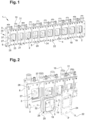
- the mold 1 shown on figure 1 in a perspective front view comprises ten mold cavities 2.
- Figure 3 shows the corresponding perspective rear view.
- the mold cavities 2 are identical, and in particular have an identical cross section, but in other embodiments they can have different cross sections and/or sizes.
- Each mold cavity 2 has a liquid metal inlet 3 (visible on figure 3 ) and a mold outlet 4. During the continuous casting process, liquid metal will be introduced into the mould cavity 2 through its inlet 3, and a solidified metal strand (not shown on the figures) will emerge from said mold outlet 4.
- the body 8 of the mold 1 comprises several parts, namely a front plate 28 and a back plate 29, held together by appropriate means 9 for fastening or assembling, such as bolts.
- the back plate 29 comprises the liquid metal inlet 3, whereas the front plate 28 comprises the mold outlet 4.
- Said body 8, front plate 28 and back plate 29 are typically made from metalic materials having a good thermal conductivity.
- the following metals and their alloys can be used: aluminium, copper, titanium, as well as stainless steel.
- the back plate 29 is typically made from steel, and the front plate 28 is typically made from copper or aluminium, whereas the body 8 is advangeously made from copper.
- the inner surface (called here « contact surface ») of a mold is in contact with liquid metal and solid metal, and is subject to friction and wear.
- at least part of the contact surface is the inner surface of a sleeve which can be replaced if needed.
- This sleeve takes the form of an insert 20, which protects at least part of the mold cavity.
- said insert forms the perimeter wall 5 of the mold cavity 2.
- Said insert 20 is substantially rectangular in cross section; its edges may be rounded.
- the insert 20 is fixed with an insert clamping plate 24 against the front plate 28 using fixing means such as bolts 22. This can be seen from figure 1 , as well as from figure 2 which shows an enlarged exploded perspective front view of the mold of figure 1 . As can be seen, the insert 20 can be removed by unlocking said fixing means 22 and removing the clamping plate 24.
- any direct contact between the inner surface of the mold body 8 and the liquid metal is avoided. Instead, it is the perimeter wall 5 of the protective insert 20 that will be in contact with the liquid metal. Said protective insert 20 is in thermal contact with a cooling fluid. Said protective insert 20 being subject to wear, it can be replaced if necessary.
- Protective inserts 20 with a cross section that is substantially rectangular are shown in figures 1 to 5 for a first embodiment; protective inserts having a cross section that is substantially circular can be used for billet casting (not shown of the figures).
- FIG. 3 shows a perspective rear view of the mold of figure 1 .
- the liquid metal enters the liquid metal inlet 3 through the nozzle plate 25 having a substantially circular perimeter wall 27.
- the nozzle plate 25 is fixed against the back plate 29 of the mold body 8 by nozzle clamping plate 26 using a fixation means 22 such as bolts.
- Figure 4 shows an enlarged exploded perspective rear view of the mold of figure 1 . Insert 20 has been introduced from the front side, and nozzle plate 25 is inserted from the rear side, abutting against the insert 20; the back plate 29 is then pressed against nozzle plate 25 using said fixation means 22.
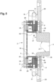
- FIG 5 shows a cross section of a mold cavity 2 similar to that shown on figures 1 to 4 .
- Said nozzle plate 25 has an opening acting an the liquid metal inlet 3, delimited by a perimeter wall 27, and a substantially flat bottom portion 37, the front surface 35 of which abuts against the rear surface 36 of the insert 20.
- One or more O-rings 40 can be used to ensure tightness of this abutment.
- the mold 1 is provided with cooling means.
- Said cooling means are of at least two kinds: the mold itself is cooled by a cooling fluid that circulates in cooling channels 39 (so-called primary cooling means), and a plurality of spray nozzles 19 are provided at the mold outlet 4 for spraying a cooling fluid onto the emerging metal strand are provided (so-called secondary cooling means). This will now be explained in more detail.
- Said primary and secondary cooling means are provided in the form of at least one cooling fluid circuit.
- a circuit for cooling fluid is provided in the mold body 8, said circuit comprising cooling fluid channels 39 and/or a cooling fluid box 30 (as in the embodiment of figure 1 ).
- An appropriate connection interface 18 is provided to connect said cooling fluid circuit to an external supply of cooling fluid.
- Said cooling circuit carries the cooling fluid through channels 39 arranged in the mold body 8, and in particular in the outlet part of the mold, in order to cool said mold body 8 and in particular said outlet part.
- the cooling circuit will here also be called a « water circuit » and the cooling fluid box 30 will here also be called a "water box”, which does however not imply that other fluids cannot be used (such as water - glycol mixtures).
- FIG. 5 shows the waterbox circuit 39, which ensures primary cooling of the mold.
- Said cooling fluid channel 39 (called here also « water channel ») is provided in vicinity of the mold body 8 and preferably, as in figure 5 , adjacent to the mold body 8, so as to ensure excellent thermal contact with the perimeter wall 32, said perimeter wall 32 being itself in thermal contact with the hot metal being cast.
- the cooling fluid circulating in said fluid channel 39 is therefore a means to cool the liquid metal during casting, as it passes through the insert 20: in contact with the perimeter wall the liquid metal will solidify at least in a certain thickness from its surface, said thickness in a given portion of metal being increasing as said metal portion is passing through the insert 20.
- the length of said perimeter wall 32 in the direction of advancement of the metal during casting is advantageously comprised between about 10 mm and about 60 mm, preferably at least 15 mm, more preferably at least 20 mm, and still more preferably at least 25 mm. If the length is too small, the cooling effect is insufficient. If the length is too high, lubructaion of the interface between the metal strand and the perimeter wall 32 may become unstable, leading to an insufficient surface quality of the cast metal strand.
- said cooling fluid box 30 is defined by the front plate 28 of the mold 1, by the mold body 8, and by the outer perimeter wall 32 of metallic insert 20. Cooling fluid enters and leaves the mold 1 through appropriate connection interfaces 18.
- One or more O-rings 40 can be used to ensure tightness of the various conduits of the waterbox circuit. As these O-rings are inserted in a cooled zone of the mold, they can be made of elastomeric materials such as synthetic rubber.
- the water box 30 can be defined also by the back plate 29 of the mold 1, and/or the water channel 39 can be provided in the mold body 8.
- means for secondary cooling of the solid surface of the solidifying metal strand are provided by a set of spray nozzles 19 provided in an annular zone around the outlet of the insert 20. They are configured such as to spray cooling fluid in an annular zone over the surface of the metal strand as it emerges from the mold outlet.
- cooling fluid used for cooling the mold will leave the mold through the spray nozzles 19.
- the waterbox circuit 39 as well as said spray nozzles 19 are in fluid connection with the connection interfaces 18 for the fluid circuit. It would however be within the scope of the invention to use separate cooling fluid circuits for the primary cooloing means and the secondary cooling means; in this case said cooling fluids can be identical or different.
- the surface of the perimeter wall 5 of the mold is lubricated during casting.
- the mold 1 comprises a dedicated circuit (called here « oil circuit ») that carries a separating agent, said circuit comprising at least one channel.
- This separating agent also called « lubrication agent » or simply « oil »
- Lubrication should be permanent and stable, in order to avoid ripples and other defects on the surface of the metal strand.
- Said separating agent can be an oil or an oily liquid such as an oil-water mixture.
- said oil can be selected from the group formed by: vegetable oil(s), refined vegetable oil(s), refined mineral oil(s), synthetic oil(s), mixtures of the mentioned oils.
- the mold body 8 is provided with conduits 38 which extend into the insert 20, until close to the perimeter wall 5.
- Said conduits 38 which are in fluid connection with a specific connection interface 31, extend until close to the edge 40 or interface between the mold body 8 and the nozzle plate 25; a small opening (not shown on the figures) may be provided to allow oil to penetrate until the edge 40 or close to said edge of the perimeter wall 5, where it can access to the surface of the emerging metal strand.
- Said opening advantageously has a diameter comprised between 0.1 mm and 1.0 mm, preferably between 0.25 mm et 0.75 mm.
- This system of conduits is used to inject oil at a remote position of the perimeter wall 5, namely close to, or at, said edge 40. Said oil will form a continuous and homogeneous thin film on the whole surface of the emerging metal strand, as soon as it will solidify in contact with the perimeter wall 5. This continous and homogeneous lubrication leads to an excellent surface quality of the as-cast metal strands.
- Said oil circuit is in fluid connection with an oil pump (not shown on the figures).
- One single oil pump can be used for the mold.
- each mold cavity 2 has its own means of adjustment (not shown on the figures) for the oil pressure and/or the oil throughput.
- This single strand lubrication approach allows to adjust the lubrication individually for each mold cavity, taking into account in particular the surface aspect of the emerging metal strands. Said adjustment can be carried manually or automatically.
- a camera coupled with appropriately configured image analysis software run on a control computer can be used to identify any significant surface defecets that coud be avoided by improving lubrication; a feedback loop can be provided between the camera and the means of adjustment for oil pressure and/or oil throughput.
- air cooling can be provided as an additional cooling means, as an additional air circuit (not shown on the figures) for supplying comppressed air blown on the mold and/or on the emerging metal strand.
- This air circuit is optional.
- the protective insert 20 is made from a material that is relatively inert with respect to the liquid metal and which does not stick to the liquid metal.
- Graphite can be used as a material for said protective insert 20, as it is chemically inert and self-lubricating.
- the insert 20 is a metallic insert.
- An insert made in aluminium or copper is preferred for molds intended to be used for casting aluminium.
- metallic materials based on aluminium or copper are not auto-lubricating like graphite, they have signficant advantages over graphite: their thermal conductivity is much higher than that of graphite, they have a significantly longer lifetime, they are less expensive, and can be recycled.
- Said metallic inserts can be manufactured by casting and/or by machining, or by additive techniques (so-called 3D printing). Cast perimeter surfaces need to be machined prior to their first use. All machined perimeter surfaces are advantageously polished, preferably after each use. After removal of the insert from the mold, the insert can be inspected and repaired if needed, or discarded for recycling if repair is not possible. Discarded metal inserts can be recycled (usially by remelting), which is hardly possible with graphite.
- the lifetime of perimeter walls made from graphite is usually of the order of 250 h to 500 h.
- the inventors have found that perimeter walls made from aluminium alloys have a lifetime that is significantly higher than that of graphite, and in particular the lifetime of the metallic insert 20 can be in excess of 1 000 hours.
- the nozzle plate 25 needs to be changed typically after 60 h to 80 h.
- a method for changing the nozzle plate 25 In a first step the fixation means 22 of the nozzle clamping plate 26 are unlocked. In a second step the nozzle clamping plate 26 is removed. In a third step the nozzle plate 26 is removed. In a fourth step a new or renovated nozzle plate 25 is put in place. In a fifth step the nozzle clamping plate 26 is reinstalled. In a sixth step the nozzle clamping plate 26 is fixed by fastening the fixation means 22. During nozzle plate change all other components of the mold can remain mounted, only the nozzle clamping plate 26 and the fixation means 22 have to be dismounted to allow change of the nozzle plate 25.
- the surfaces of the removed nozzle clamping plate 26 are cleaned before it is put in place in the third step, or another cleaned, new or renovated nozzle clamping plate is used.
- the visible surface of the back plate 29 is cleaned between the second and the fourth step, as well as all accessible surfaces of the mold cavity.
- a method for changing the mold insert 20 In a first step the fixation means of the insert clamping plate 24 are unlocked. In a second step the insert clamping plate 24 is removed. In a third step all accessible surfaces of the mold cavity are cleaned. In a fourth step a new (or renovated) mold insert 20, and preferably a new O-ring, are installed. In a fifth step the insert clamping plate 24 is resintalled. In a sixth step the insert clamping plate 24 is fixed by fastening the fixation means. During insert plate change all other components of the mold can remain mounted, only the insert clamping plate 24 and the fixation means have to be dismounted.
- the invention has many advantages.
- One of the advantages of the invention is that the body 8 is not subject to wear, but only the insert 20 and the nozzle plate 25, both of which can be exchanged individually if necessary, using a simple and fast method.
- the insert 20 and the nozzle plates 25 are metallic parts that can be manufactured easily and which are rather inexpensive; moreover they can be recycled easily after having been discarded.
- the perimeter wall 5 is made from metal, such as aluminium alloy, which has a higher thermal conductivity than graphite, thereby allowing better cooling of the whole surface of the perimeter wall 5. Lubrication is efficient, and is limited to the part of the interface where it is absolutely necessary; this allows to use a small amount of lubrication agent (such as oil) only.
- the lubrication agent is used in a mixture with water, which acts as coolant.
- the quantity coolant (water - lubrication agent mixture) and / or lubrication agent can be adjusted for each individual mold cavity, according to what is needed to ensure sufficient lubrication.
- the mould 1 ccoding to the invention can have one single mold cavity, or a plurality of mold cavities; figure 1 shows a typical embodiment with ten identical mold cavities 2.
- the mold cavities 2 can be different, although this would not be a preferred embodiment of the invention.
- the mold and casting process according to the invention has been used for horizontal casting of foundry ingots (so-called HDC ingots or Horizontal Direct Chilled ingots) in various aluminium alloys, with a width of about 55 mm and a height of about 75 mm or 90 mm, which can be used for remelting in various casting processes, such as die casting.
- the temperature range of the cooling water was between about 5 °C and about 50 °C
- the volume of cooling water per cast mass of aluminium was between about 5 Nm 3 /t and about 40 Nm 3 /t
- the volume of cooling water per strand and hour was comprised between about 2.3 Nm 3 /h and 18.2 Nm 3 /h
- the volume of lubrication agent per cast mass of aluminium was comprised between 10 mL/t and 400 mL/t
- the volume of lubrication agent per strand and hour was comprised between about 0.5 mL/h and 18.5 mL/h
- the casting speed was between about 0.1 mm/s and about 15 mm/s.
- Said lubrication agent can typically be used in a concentration of about 0.2 L/m 3 of water.
Abstract
Mold (1) for semi-continuous casting of metal strands from liquid metal, comprising a mold body (8) provided with at least one mold cavity (2), said mold cavity comprising:- a liquid metal inlet (3) defined by a nozzle plate (25),- an insert (20), said insert (3) defining a perimeter wall (5) intended to be in contact with the metal leaving said liquid metal inlet (3),- a mold outlet (4),- a plurality of spray nozzles (19) for spraying cooling fluid onto said metal strand, said spray nozzles being preferably provided in said insert (20),characterized in that said mold body (8) is provided with a channel (39) for cooling fluid, and in that said insert (20) is removable, and is made from a metallic material. This mold is useful for casting aluminium strands.
Description
- The invention relates to the field of casthouse technology, and more precisely to machines for casting metal strands by direct chill (DC) casting. DC casting is a continous (or more precisely, semi-continuous) casting process, and is of widespread use, in particular for casting certain non ferrous metals and alloys. In particular the present invention relates to a novel mold for semi-continuous casting machines for casting strands or ingots in non-ferrous metals and alloys that are neither precious metals nor refractory metals, and in particular in aluminium and aluminium alloys.
- The invention also relates to a method of casting a metal strand or ingot using such a mold, and to metal strands obtained by this method. The invention also relates to a method for maintaining or repairing said mould.
- Casting machines for transforming molten metal into a solid, elongated body of metal are known for a long time. Open ended, cooled moulds with an inner perimeter wall are used for a so-called continous (or rather semi-continuous) casting process. At the beginning of this casting process, liquid metal is poured through said open ended mold which is closed by a starting block, also called bottom block. As the metal is solidifying in the neighborhood of the inner perimeter wall of the mould, the bottom plate advances into the casting direction, which may be vertical (and in this case downwards) or horizontal, while the emerging metal strand is cooled. Cooling of the emerging metal strand is usually achieved by water that is sprayed over the metal strand as it emerges from the mould outlet; for this reason this process is also called « chill casting ». When emerging from the mold outlet, the metal strand may still be liquid or semi-solid in its centre, and will completely solidify in a few seconds under the effect of water-chilling as it moves away from the mould outlet.
- This process allows to produce metal strands with a substantially constant cross section; their length is limited by the dimensions of the equipment (namely the depth of the casting pit, in the case of vertical casting, or the length of the structure supporting the horizontally emerging metal strand), by the available quantity of liquid metal, and by the overall stability of the casting process. For increased productivity, multiple strands can be cast in one run from liquid metal: to this end, a plurality of molds is provided in a so-called casting table. For billet casting, casting tables with several dozens of molds are used, depending on the diameter of the billets.
- Molds for continous casting are usually complex tools made from chemically resistant materials with good thermal conductivity; they comprise a perimeter wall that is in contact with the liquid and solidifying metal, as well as cooling means. Cooling of the metal is usually achieved by water that is sprayed over the metal strand as it emerges from the outlet of mold.
- Perimeter walls have a contact surface that experiences friction with the outer surface of the solidifying metal strand; they need to be lubricated in order to minimize wear and tear. When the surface state of a perimeter wall is terminally degraded such that the mold does no longer allow to cast billets with the required surface quality, the mold can be disabled in the casting table; this allows to continue the use of the casting table, but with decreased productivity.
- Perimeter walls can be made from various materials. They can be made from metallic materials such as steel, and will then need to be lubricated. They can also be made from graphite, which is a chemically inert, auto-lubricating material resisting to fairly high temperatures. Additional lubrication by appropriate lubricants can be provided, as graphite is porous and will let pass a certain amount of lubricant or gas, depending on the applied pressure, on the temperature, and on the effective contact surface. Such graphite perimeter walls can be made as inserts (sleeves) which can be replaced if necessary.
- Certain prior art continuous billet casting systems for liquid aluminium are provided with a permeable or porous graphite perimeter wall through which lubricant and gas are distributed to the inside surface of the mold. This has been described in
US 4,598,763 (Wagstaff ).WO 95/23044 (Wagstaff US 2007/0163746 desribes an improved perimeter wall lubrication system for molten aluminium molds using for billet casting, achieving a more even flow of lubricant through the peripheral wall. - One objective of the present invention is to provide a mold for ingot casting that has improved lifetime, and that can be cleaned, repaired or renovated easily.
- Another objective of the present invention is to provide a casting table and mold for multiple strand ingot casting that have improved lifetime.
- Another objective of the invention is to improve the overall process stability of multiple strand ingot casting, while increasing casting speed (expressed, for a given cross section, in length of the metal strand per time unit), and in particular to improve the stability of the lubrication at the interface between the mold and the emerging metal surface.
- Yet another objective of the invention is to improve the process control of multiple strand ingot casting.
- Yet another objective of the invention is to decrease the quantity of lubricant used in multiple strand ingot casting, while ensuring sufficient and stable lubrication at the interface between the mold and the emerging metal surface.
- According to the invention, these problems are solved by several means that cooperate with each other.
- One essential feature of the invention is cooling of the mold body. According to prior art, during continuous casting a cooling fluid, usually water, is sprayed on the emerging strand of solidifying metal. As a result of the mold design according to the invention, there are at least two independent means of cooling.
- Primary cooling is achieved through the mold body which is cooled from its inside during the casting operation. More precisely, the mold body is cooled by a cooling liquid circulating in cooling channels arranged in the wall of the mold; this allows efficient cooling of the peripheral wall of the mold which is in contact with the solidifying metal.
- Secondary cooling is achieved by a water spray: The surface of the emerging metal strand is cooled by cooling fluid sprayed in an annular zone all over the surface of the strand.
- In addition to these primary and secondary cooling means, the surface of the peripheral wall of the mold which is in contact with the solidifying metal is lubricated by an appropriate lubricant, such as oil or a mixture of oil and water. The use of a lubricant improves the surface quality of the emerging metal strand throughout the continous casting process which proceeds under dynamic and steady state conditions.
- Another essential feature of the invention is the use of a removable insert defining the perimeter wall which will be in contact with the solidifying metal. This allows efficient inspection, maintenance and repair of the mold, without disabling defective mold cavities in the case of mulitple-strand molds. This insert may be a copper insert, but is advantageously made from aluminium or aluminium alloy. Surprisingly, the contact between the solidifying and moving aluminium skin of the metal strand being cast and the solid aluminium insert allows to obtain an excellent surface quality, especially if a lubricant is used.
- The present invention is particularly useful for horizontal casting.
- A first object of the invention is a mold for semi-continuous casting of metal strands from liquid metal, comprising a mold body provided with at least one mold cavity, said mold cavity comprising:
- a liquid metal inlet defined by a nozzle plate,
- an insert, said insert defining a perimeter wall intended to be in contact with the metal leaving said liquid metal inlet,
- a mold outlet comprising a plurality of spray nozzles for spraying cooling fluid onto said metal strand,
- During casting operation, liquid metal will be admitted to the mold through said nozzle plate and flows through said insert, which is arranged downstream of said liquid metal inlet. Said insert is cooled by a cooling fluid circulating in said channel. Said channel for cooling fluid is in fluid connection with a connection interface for cooling fluid. The liquid metal solidifies in contact with the cooled insert, and when leaving the mold outlet, at least the surface of the metal strand will be solid. At the mold outlet, cooling fluid is sprayed onto the surface of the metal strand as it leaves the mold.
- Said nozzle plate is advantageously made from a non metallic inorganic material, and preferably from a ceramic material.
- Said insert is adavantageously made from copper or copper alloy, or from aluminium or aluminium alloy. These materials have a high thermal conductivity, are fully recyclable and easy to machine. Machinability is a significant asset here because it allows to provide the insert with a plurality of spraying nozzles by which the cooling fluid used for primary cooling of the insert is sprayed onto the merging metal strand.
- According to advantageous embodiments of the invention:
- said mold body is provided with a removable front plate;
- said channel for cooling fluid is arranged in said mold body or adjacent to said mold body;
- said mold body, said insert and said front plate define a waterbox, said waterbox preferably comprising said channel for cooling fluid;
- said channel for cooling fluid is arranged in said mold body or between said mold body and said insert, or between said mold body, said insert and said front plate.
- The mold according to the invention can further comprise a removable insert clamping plate, fixed onto said front plate and capable of clamping said insert against said nozzle plate.
- Said insert can be clamped between said nozzle plate, using a nozzle clamping plate, and said mold body, using an insert clamping plate. This allows easy removal of the insert, for inspection, repair, maintenance and/or replacement. Said insert has a non circular cross section, allowing to cast metal strands with a cross section that is non circular, such as foundry ingots.
- According to an advanageous embodiment, said mold further comprises at least one conduit provided in said insert which is in fluid connection with a connection interface for a lubricant fluid. In particular, said conduit is designed for admitting a lubricant fluid between said insert and said nozzle plate.
- The mold according to the invention can comprise comprise a plurality of mold cavities, each of which showing the inventive features mentioned above. Said waterbox extends substantially over the whole mold. In an advantageous embodiment the number of mold cavities is comprised between five and twenty. Said mold cavities are advantageouysly aligned on one single axis. They can be identical or not.
- In an advantageous embodiment each mold cavity has its own means of adjustment for the pressure and/or the throughput of said lubricant fluid.
- Another object of the invention is the use of a mold according to any of the embodimets of the invention for casting of metal strands with a non circular cross section, said metal strands being preferably foundry ingots. During casting, cooling fluid is circulated in said cooling channels and/or said waterbox, and/or cooling fluid is sprayed onto the metal strand emerging from the mold outlet using said nozzles, and/or lubricant fluid is admitted through said conduits surface of said metal strand.
- Another object of the invention is a method for casting a metal strand from liquid metal, in particular a metal strand for use as a foundry ingot, using said mold according to the invention, with the proviso that said metal strand does not have a circular cross section. In this method, the temperature of the cooling water is typically between about 5 °C and about 50 °C, the volume of cooling water per cast mass of aluminium is between about 5 Nm3/t and about 40 Nm3/t, the volume of lubrication agent per cast mass of aluminium is comprised between about 5 mL/t and about 400 mL/t, the volume of lubrication agent per strand and hour is comprised between about 0.5 mL/h and 18.5 mL/h, and the casting speed was between about 0.1 mm/s and about 15 mm/s. Said lubrication agent can typically be used in a concentration of between about 0.05 L/m3 and about 2 L/m3 of water, preferably between about 0.1 L/m3 and about 0.8 L/m3 of water, and more preferably between about 0.14 L/m3 and about 0.6 L/m3 of water. If there is not enough lubrication, the surface of the metal strand shows inceased surface roughness; if there is too much lubrication the surface of the metal strand may show ripples.
- Another object of the invention is a method of maintaining or repairing a mold according to the invention, wherein said insert clamping plate is removed, said insert is removed for inspection and/or maintenance and/or repair and/or replacement, another or the same insert is inserted, and said insert claming plate is put in place again and fastened. Said maintenace or repair can comprise polishing of the perimeter surface prior to putting in place the insert again.
-
Figures 1 to 5 represent various aspects and embodiements of the invention. They are given for illustration only, and are not meant to limit the scope of the invention. -
Figure 1 shows a perspective front view of a multiple-strand mold for ingots with substantially rectangular cross section according to the invention, capable of producing up to ten cast bars. -
Figure 2 shows an exploded and enlarged perspective front view of the multiple-strand mold offigure 1 . -
Figure 3 shows a perpective rear view of the mold offigure 1 . -
Figure 4 shows an exploded and enlarged perspective rear view of the mold offigure 1 . -
Figure 5 shows a cross section of the mold according tofigure 1 . - The following reference numbers are used on the figures and in the description:
1 Mold according to the invention 2 Mold cavity 3 Liquid metal inlet 4 Mold outlet 5 Perimeter wall of the mold 6 Solidified metal strand 8 Mold body 9 Assembling or fixation means 18 Connection interface for water circuit 19 Spray nozzles for cooling fluid 20 Protective insert 22 Assembly or fixation means 24 Insert clamping plate 25 Nozzle plate 26 Nozzle clamping plate 27 Perimeter wall of 3 28 Front plate 29 Back plate 30 Water box 31 Connection interface for oil circuit 32 Outer perimeter wall of insert 2035 Front surface of 25 36 Rear surface of 20 37 Bottom portion of 25 38 Conduit 39 Channel for cooling fluid 40 O-ring - The term "aluminium" as used herein includes aluminium alloys, and the term "copper" as used herein includes copper alloys.
- Typical molds according to the invention will be described here in relation with
figures 1 to 5 . - The
mold 1 shown onfigure 1 in a perspective front view comprises tenmold cavities 2.Figure 3 shows the corresponding perspective rear view. In this embodiment themold cavities 2 are identical, and in particular have an identical cross section, but in other embodiments they can have different cross sections and/or sizes. Eachmold cavity 2 has a liquid metal inlet 3 (visible onfigure 3 ) and a mold outlet 4. During the continuous casting process, liquid metal will be introduced into themould cavity 2 through itsinlet 3, and a solidified metal strand (not shown on the figures) will emerge from said mold outlet 4. - The
body 8 of themold 1 comprises several parts, namely afront plate 28 and aback plate 29, held together byappropriate means 9 for fastening or assembling, such as bolts. Theback plate 29 comprises theliquid metal inlet 3, whereas thefront plate 28 comprises the mold outlet 4.Said body 8,front plate 28 and backplate 29 are typically made from metalic materials having a good thermal conductivity. As an example, the following metals and their alloys can be used: aluminium, copper, titanium, as well as stainless steel. As an example, if themold 1 is intended to be used for casting aluminium or aluminium alloys, theback plate 29 is typically made from steel, and thefront plate 28 is typically made from copper or aluminium, whereas thebody 8 is advangeously made from copper. - The inner surface (called here « contact surface ») of a mold is in contact with liquid metal and solid metal, and is subject to friction and wear. According to the invention, at least part of the contact surface is the inner surface of a sleeve which can be replaced if needed. This sleeve takes the form of an
insert 20, which protects at least part of the mold cavity. In particular, said insert forms theperimeter wall 5 of themold cavity 2. Saidinsert 20 is substantially rectangular in cross section; its edges may be rounded. Theinsert 20 is fixed with aninsert clamping plate 24 against thefront plate 28 using fixing means such asbolts 22. This can be seen fromfigure 1 , as well as fromfigure 2 which shows an enlarged exploded perspective front view of the mold offigure 1 . As can be seen, theinsert 20 can be removed by unlocking said fixing means 22 and removing the clampingplate 24. - According to the invention, any direct contact between the inner surface of the
mold body 8 and the liquid metal is avoided. Instead, it is theperimeter wall 5 of theprotective insert 20 that will be in contact with the liquid metal. Saidprotective insert 20 is in thermal contact with a cooling fluid. Saidprotective insert 20 being subject to wear, it can be replaced if necessary. Protective inserts 20 with a cross section that is substantially rectangular are shown infigures 1 to 5 for a first embodiment; protective inserts having a cross section that is substantially circular can be used for billet casting (not shown of the figures). - On the rear of the
mold 1, theinsert 20 is completed by anozzle plate 25. This can be seen fromFigure 3 which shows a perspective rear view of the mold offigure 1 . The liquid metal enters theliquid metal inlet 3 through thenozzle plate 25 having a substantiallycircular perimeter wall 27. Thenozzle plate 25 is fixed against theback plate 29 of themold body 8 bynozzle clamping plate 26 using a fixation means 22 such as bolts.Figure 4 shows an enlarged exploded perspective rear view of the mold offigure 1 .Insert 20 has been introduced from the front side, andnozzle plate 25 is inserted from the rear side, abutting against theinsert 20; theback plate 29 is then pressed againstnozzle plate 25 using said fixation means 22. - This can be seen from
figure 5 which shows a cross section of amold cavity 2 similar to that shown onfigures 1 to 4 . Saidnozzle plate 25 has an opening acting an theliquid metal inlet 3, delimited by aperimeter wall 27, and a substantiallyflat bottom portion 37, thefront surface 35 of which abuts against therear surface 36 of theinsert 20. One or more O-rings 40 can be used to ensure tightness of this abutment. - According to the invention, the
mold 1 is provided with cooling means. Said cooling means are of at least two kinds: the mold itself is cooled by a cooling fluid that circulates in cooling channels 39 (so-called primary cooling means), and a plurality ofspray nozzles 19 are provided at the mold outlet 4 for spraying a cooling fluid onto the emerging metal strand are provided (so-called secondary cooling means). This will now be explained in more detail. - Said primary and secondary cooling means are provided in the form of at least one cooling fluid circuit. A circuit for cooling fluid is provided in the
mold body 8, said circuit comprising coolingfluid channels 39 and/or a cooling fluid box 30 (as in the embodiment offigure 1 ). Anappropriate connection interface 18 is provided to connect said cooling fluid circuit to an external supply of cooling fluid. Said cooling circuit carries the cooling fluid throughchannels 39 arranged in themold body 8, and in particular in the outlet part of the mold, in order to cool saidmold body 8 and in particular said outlet part. As the most frequently used cooling fluid is water, the cooling circuit will here also be called a « water circuit » and the coolingfluid box 30 will here also be called a "water box", which does however not imply that other fluids cannot be used (such as water - glycol mixtures). -
Figure 5 shows thewaterbox circuit 39, which ensures primary cooling of the mold. Said cooling fluid channel 39 (called here also « water channel ») is provided in vicinity of themold body 8 and preferably, as infigure 5 , adjacent to themold body 8, so as to ensure excellent thermal contact with theperimeter wall 32, saidperimeter wall 32 being itself in thermal contact with the hot metal being cast. The cooling fluid circulating in saidfluid channel 39 is therefore a means to cool the liquid metal during casting, as it passes through the insert 20: in contact with the perimeter wall the liquid metal will solidify at least in a certain thickness from its surface, said thickness in a given portion of metal being increasing as said metal portion is passing through theinsert 20. - The length of said
perimeter wall 32 in the direction of advancement of the metal during casting is advantageously comprised between about 10 mm and about 60 mm, preferably at least 15 mm, more preferably at least 20 mm, and still more preferably at least 25 mm. If the length is too small, the cooling effect is insufficient. If the length is too high, lubructaion of the interface between the metal strand and theperimeter wall 32 may become unstable, leading to an insufficient surface quality of the cast metal strand. - In the embodiment of
figure 5 , said coolingfluid box 30 is defined by thefront plate 28 of themold 1, by themold body 8, and by theouter perimeter wall 32 ofmetallic insert 20. Cooling fluid enters and leaves themold 1 through appropriate connection interfaces 18. One or more O-rings 40 can be used to ensure tightness of the various conduits of the waterbox circuit. As these O-rings are inserted in a cooled zone of the mold, they can be made of elastomeric materials such as synthetic rubber. - In other embodiments (not shown on the figures) the
water box 30 can be defined also by theback plate 29 of themold 1, and/or thewater channel 39 can be provided in themold body 8. - In addition to primary cooling of the mold itself, and in particular of its perimeter wall, means for secondary cooling of the solid surface of the solidifying metal strand are provided by a set of
spray nozzles 19 provided in an annular zone around the outlet of theinsert 20. They are configured such as to spray cooling fluid in an annular zone over the surface of the metal strand as it emerges from the mold outlet. - Typically one single cooling circuit is provided for both primary and secondary cooling means, as in the figures, and the cooling fluid used for cooling the mold will leave the mold through the
spray nozzles 19. In the embodiment offigures 1 to 4 , thewaterbox circuit 39 as well as saidspray nozzles 19 are in fluid connection with the connection interfaces 18 for the fluid circuit. It would however be within the scope of the invention to use separate cooling fluid circuits for the primary cooloing means and the secondary cooling means; in this case said cooling fluids can be identical or different. - According to an advantageous feature of the invention, the surface of the
perimeter wall 5 of the mold is lubricated during casting. To this end, themold 1 comprises a dedicated circuit (called here « oil circuit ») that carries a separating agent, said circuit comprising at least one channel. This separating agent (also called « lubrication agent » or simply « oil ») has has two functions: it lubricates the interface between said metal surface and theinner perimeter wall 5 of theinsert 20, and it contributes ( as a socalled "tertiary cooling means") to cooling the emerging metal surface of the cast strand. Lubrication should be permanent and stable, in order to avoid ripples and other defects on the surface of the metal strand. To this end, openings are provided in theinsert 20 and/or themold body 8, allowing oil to penetrate and to access to the surface of the emerging metal strand. Said separating agent can be an oil or an oily liquid such as an oil-water mixture. For example, said oil can be selected from the group formed by: vegetable oil(s), refined vegetable oil(s), refined mineral oil(s), synthetic oil(s), mixtures of the mentioned oils. - More precisely, as can be seen from
figure 5 , themold body 8 is provided withconduits 38 which extend into theinsert 20, until close to theperimeter wall 5. Saidconduits 38, which are in fluid connection with aspecific connection interface 31, extend until close to theedge 40 or interface between themold body 8 and thenozzle plate 25; a small opening (not shown on the figures) may be provided to allow oil to penetrate until theedge 40 or close to said edge of theperimeter wall 5, where it can access to the surface of the emerging metal strand. Said opening advantageously has a diameter comprised between 0.1 mm and 1.0 mm, preferably between 0.25 mm et 0.75 mm. There may be provided more than one ofsuch conduits 38 for eachmold cavity 2, preferably on each of the sides of the cross section. This system of conduits is used to inject oil at a remote position of theperimeter wall 5, namely close to, or at, saidedge 40. Said oil will form a continuous and homogeneous thin film on the whole surface of the emerging metal strand, as soon as it will solidify in contact with theperimeter wall 5. This continous and homogeneous lubrication leads to an excellent surface quality of the as-cast metal strands. - Said oil circuit is in fluid connection with an oil pump (not shown on the figures). One single oil pump can be used for the mold. According to an advantageous embodiment of the invention, each
mold cavity 2 has its own means of adjustment (not shown on the figures) for the oil pressure and/or the oil throughput. This single strand lubrication approach allows to adjust the lubrication individually for each mold cavity, taking into account in particular the surface aspect of the emerging metal strands. Said adjustment can be carried manually or automatically. A camera coupled with appropriately configured image analysis software run on a control computer can be used to identify any significant surface defecets that coud be avoided by improving lubrication; a feedback loop can be provided between the camera and the means of adjustment for oil pressure and/or oil throughput. - In a variant of the invention, air cooling can be provided as an additional cooling means, as an additional air circuit (not shown on the figures) for supplying comppressed air blown on the mold and/or on the emerging metal strand. This air circuit is optional.
- The
protective insert 20 is made from a material that is relatively inert with respect to the liquid metal and which does not stick to the liquid metal. Graphite can be used as a material for saidprotective insert 20, as it is chemically inert and self-lubricating. According to a particularly advantageous embodiment of the invention, theinsert 20 is a metallic insert. An insert made in aluminium or copper is preferred for molds intended to be used for casting aluminium. Although metallic materials based on aluminium or copper are not auto-lubricating like graphite, they have signficant advantages over graphite: their thermal conductivity is much higher than that of graphite, they have a significantly longer lifetime, they are less expensive, and can be recycled. Said metallic inserts can be manufactured by casting and/or by machining, or by additive techniques (so-called 3D printing). Cast perimeter surfaces need to be machined prior to their first use. All machined perimeter surfaces are advantageously polished, preferably after each use. After removal of the insert from the mold, the insert can be inspected and repaired if needed, or discarded for recycling if repair is not possible. Discarded metal inserts can be recycled (usially by remelting), which is hardly possible with graphite. - The lifetime of perimeter walls made from graphite is usually of the order of 250 h to 500 h. The inventors have found that perimeter walls made from aluminium alloys have a lifetime that is significantly higher than that of graphite, and in particular the lifetime of the
metallic insert 20 can be in excess of 1 000 hours. Thenozzle plate 25 needs to be changed typically after 60 h to 80 h. - We will describe now in relation with
figure 4 a method for changing thenozzle plate 25. In a first step the fixation means 22 of thenozzle clamping plate 26 are unlocked. In a second step thenozzle clamping plate 26 is removed. In a third step thenozzle plate 26 is removed. In a fourth step a new or renovatednozzle plate 25 is put in place. In a fifth step thenozzle clamping plate 26 is reinstalled. In a sixth step thenozzle clamping plate 26 is fixed by fastening the fixation means 22. During nozzle plate change all other components of the mold can remain mounted, only thenozzle clamping plate 26 and the fixation means 22 have to be dismounted to allow change of thenozzle plate 25. The surfaces of the removednozzle clamping plate 26 are cleaned before it is put in place in the third step, or another cleaned, new or renovated nozzle clamping plate is used. The visible surface of theback plate 29 is cleaned between the second and the fourth step, as well as all accessible surfaces of the mold cavity. - We will describe now in relation with
figure 2 a method for changing themold insert 20. In a first step the fixation means of theinsert clamping plate 24 are unlocked. In a second step theinsert clamping plate 24 is removed. In a third step all accessible surfaces of the mold cavity are cleaned. In a fourth step a new (or renovated)mold insert 20, and preferably a new O-ring, are installed. In a fifth step theinsert clamping plate 24 is resintalled. In a sixth step theinsert clamping plate 24 is fixed by fastening the fixation means. During insert plate change all other components of the mold can remain mounted, only theinsert clamping plate 24 and the fixation means have to be dismounted. - The invention has many advantages. One of the advantages of the invention is that the
body 8 is not subject to wear, but only theinsert 20 and thenozzle plate 25, both of which can be exchanged individually if necessary, using a simple and fast method. Theinsert 20 and thenozzle plates 25 are metallic parts that can be manufactured easily and which are rather inexpensive; moreover they can be recycled easily after having been discarded. Theperimeter wall 5 is made from metal, such as aluminium alloy, which has a higher thermal conductivity than graphite, thereby allowing better cooling of the whole surface of theperimeter wall 5. Lubrication is efficient, and is limited to the part of the interface where it is absolutely necessary; this allows to use a small amount of lubrication agent (such as oil) only. The lubrication agent is used in a mixture with water, which acts as coolant. The quantity coolant (water - lubrication agent mixture) and / or lubrication agent can be adjusted for each individual mold cavity, according to what is needed to ensure sufficient lubrication. - The
mould 1 ccoding to the invention can have one single mold cavity, or a plurality of mold cavities;figure 1 shows a typical embodiment with tenidentical mold cavities 2. Themold cavities 2 can be different, although this would not be a preferred embodiment of the invention. - The mold and casting process according to the invention has been used for horizontal casting of foundry ingots (so-called HDC ingots or Horizontal Direct Chilled ingots) in various aluminium alloys, with a width of about 55 mm and a height of about 75 mm or 90 mm, which can be used for remelting in various casting processes, such as die casting. During these industrial casting tests, the temperature range of the cooling water was between about 5 °C and about 50 °C, the volume of cooling water per cast mass of aluminium was between about 5 Nm3/t and about 40 Nm3/t, the volume of cooling water per strand and hour was comprised between about 2.3 Nm3/h and 18.2 Nm3/h, the volume of lubrication agent per cast mass of aluminium was comprised between 10 mL/t and 400 mL/t, the volume of lubrication agent per strand and hour was comprised between about 0.5 mL/h and 18.5 mL/h, and the casting speed was between about 0.1 mm/s and about 15 mm/s. Said lubrication agent can typically be used in a concentration of about 0.2 L/m3 of water.
Claims (15)
- Mold (1) for semi-continuous casting of metal strands from liquid metal, comprising a mold body (8) provided with at least one mold cavity (2), said mold cavity comprising:- a liquid metal inlet (3) defined by a nozzle plate (25),- an insert (20), said insert (3) defining a perimeter wall (5) intended to be in contact with the metal leaving said liquid metal inlet (3),- a mold outlet (4),- a plurality of spray nozzles (19) for spraying cooling fluid onto said metal strand, said spray nozzles being preferably provided in said insert (20),
characterized in that said mold body (8) is provided with a channel (39) for cooling fluid, and in that said insert (20) is removable, and is made from a metallic material, which is preferably selected from the groupe formed by: aluminium, aluminium alloys, copper, copper alloys. - Mold (1) according to claim 1, wherein said mold body (8) is provided with a removable front plate (28).
- Mold (1) according to any of claims 1 or 2, characterized in that said channel (39) for cooling fluid is arranged in said mold body (8) or adjacent to said mold body (8).
- Mold accoding to any of claims 2 or 3, wherein said mold body (8), said insert (20) and said front plate (28) define a waterbox (30), said waterbox preferably comprising said channel (39) for cooling fluid.
- Mold (1) according to any of claims 2 to 4, characterized in that said channel (39) for cooling fluid is arranged in said mold body (8) or between said mold body (8) and said insert (20), or between said mold body (8), said insert (20) and said front plate (28).
- Mold according to any of claims 1 to 5, further comprising a removable insert clamping plate (24), fixed onto said front plate (28) and capable of clamping said insert against said nozzle plate (25).
- Mold (1) according to any of claims 1 to 4, characerized in that said insert is clamped between said nozzle plate (25), using a nozzle clamping plate (24), and said mold body, using an insert clamping plate (24).
- Mold (1) according to any of claims 1 to 7, characterized in that said nozzle plate (25) is made from a non metallic inorganic material, and preferably from a ceramic material.
- Mold (1) according to any of claims 1 to 8, further comprising at least one conduit (38) provided in said insert which is in fluid connection with a connection interface (31) for a lubricant fluid.
- Mold (1) according to claim 9, wherein said conduit (38) is designed for admitting a lubricant fluid between said insert (20) and said nozzle plate (25).
- Mold (1) according to any of claims 1 to 10, comprising a plurality of mold cavities (2).
- Mold (1) according to claim 11 depending on any of claims 4 to 10, characterized in that said waterbox (30) extends substantially over the whole mold.
- Use of a mold (1) according to any of claims 1 to 12 for casting of metal strands with a non circular cross section, said metal strands being preferably foundry ingots.
- Use according to claim 13, characterized in that during casting :- cooling fluid is circulated in said cooling channels (39) and/or said waterbox (30), and/or- cooling fluid is sprayed onto the metal strand emerging from the mold outlet (4) using said spray nozzles (19), and/or- lubricant fluid is admitted through said conduits on the surface of said metal strand.
- Method of maintaining or repairing a mold (1) according to any of claims 7 to 10, wherein said insert clamping plate (24) is removed, said insert (20) is removed for maintenance, repair or replacement, another or the same insert is inserted, and said insert clamping plate (24) is put in place again and fastened.
Priority Applications (2)
| Application Number | Priority Date | Filing Date | Title |
|---|---|---|---|
| EP22168449.1A EP4260963A1 (en) | 2022-04-14 | 2022-04-14 | Mold for continuous casting of metal strands |
| PCT/IB2023/053832 WO2023199280A1 (en) | 2022-04-14 | 2023-04-14 | Mold for continuous casting of metal strands |
Applications Claiming Priority (1)
| Application Number | Priority Date | Filing Date | Title |
|---|---|---|---|
| EP22168449.1A EP4260963A1 (en) | 2022-04-14 | 2022-04-14 | Mold for continuous casting of metal strands |
Publications (1)
| Publication Number | Publication Date |
|---|---|
| EP4260963A1 true EP4260963A1 (en) | 2023-10-18 |
Family
ID=81327602
Family Applications (1)
| Application Number | Title | Priority Date | Filing Date |
|---|---|---|---|
| EP22168449.1A Pending EP4260963A1 (en) | 2022-04-14 | 2022-04-14 | Mold for continuous casting of metal strands |
Country Status (2)
| Country | Link |
|---|---|
| EP (1) | EP4260963A1 (en) |
| WO (1) | WO2023199280A1 (en) |
Citations (6)
| Publication number | Priority date | Publication date | Assignee | Title |
|---|---|---|---|---|
| US4598763A (en) | 1982-10-20 | 1986-07-08 | Wagstaff Engineering, Inc. | Direct chill metal casting apparatus and technique |
| WO1995023044A1 (en) | 1994-02-25 | 1995-08-31 | Wagstaff, Inc. | Direct cooled metal casting process and apparatus |
| WO2001000353A1 (en) * | 1999-06-25 | 2001-01-04 | Norsk Hydro Asa | Equipment for continuous casting of metal, in particular aluminium |
| US20020148593A1 (en) * | 2000-05-15 | 2002-10-17 | Tilak Ravindra V. | Direct chill casting mold system |
| US20070163746A1 (en) | 2006-01-13 | 2007-07-19 | Anderson Michael K | Perimeter wall lubrication system for molten metal molds |
| WO2021061017A1 (en) * | 2019-09-24 | 2021-04-01 | Общество С Ограниченной Ответственностью "Объединенная Компания Русал Инженерно -Технологический Центр" | Mould for vertically casting aluminium ingots |
Family Cites Families (3)
| Publication number | Priority date | Publication date | Assignee | Title |
|---|---|---|---|---|
| GB1455403A (en) * | 1974-04-19 | 1976-11-10 | Kaiser Aluminium Chem Corp | Dc mould assembly |
| CA1275781C (en) * | 1986-05-27 | 1990-11-06 | Guy Leblanc | Modular mould system and method for continuous casting of metal ingots |
| CH689446A5 (en) * | 1995-03-24 | 1999-04-30 | Alusuisse Lonza Services Ag | Continuous casting mould of modular construction |
-
2022
- 2022-04-14 EP EP22168449.1A patent/EP4260963A1/en active Pending
-
2023
- 2023-04-14 WO PCT/IB2023/053832 patent/WO2023199280A1/en unknown
Patent Citations (6)
| Publication number | Priority date | Publication date | Assignee | Title |
|---|---|---|---|---|
| US4598763A (en) | 1982-10-20 | 1986-07-08 | Wagstaff Engineering, Inc. | Direct chill metal casting apparatus and technique |
| WO1995023044A1 (en) | 1994-02-25 | 1995-08-31 | Wagstaff, Inc. | Direct cooled metal casting process and apparatus |
| WO2001000353A1 (en) * | 1999-06-25 | 2001-01-04 | Norsk Hydro Asa | Equipment for continuous casting of metal, in particular aluminium |
| US20020148593A1 (en) * | 2000-05-15 | 2002-10-17 | Tilak Ravindra V. | Direct chill casting mold system |
| US20070163746A1 (en) | 2006-01-13 | 2007-07-19 | Anderson Michael K | Perimeter wall lubrication system for molten metal molds |
| WO2021061017A1 (en) * | 2019-09-24 | 2021-04-01 | Общество С Ограниченной Ответственностью "Объединенная Компания Русал Инженерно -Технологический Центр" | Mould for vertically casting aluminium ingots |
Also Published As
| Publication number | Publication date |
|---|---|
| WO2023199280A1 (en) | 2023-10-19 |
Similar Documents
| Publication | Publication Date | Title |
|---|---|---|
| US3286309A (en) | Method and apparatus for horizontal casting of ingots | |
| US5325910A (en) | Method and apparatus for continuous casting | |
| EP2667986B1 (en) | Coolant control and wiper system for a continuous casting molten metal mold | |
| EP1009562B9 (en) | A mould table with a system for providing consistent flow through multiple permeable perimeter walls in casting moulds | |
| EP4260963A1 (en) | Mold for continuous casting of metal strands | |
| CA2200470A1 (en) | Apparatus and method for the vertical casting of a metalbar | |
| US6315030B1 (en) | High speed continuous casting device and relative method | |
| US20120186772A1 (en) | Thermal management system for a continuous casting molten metal mold | |
| AU2016204329B2 (en) | Continuous cast molten metal mold and casting system | |
| US5785112A (en) | Method and modular continuous casting mold for manufacturing ingots | |
| US3506063A (en) | Continuous casting | |
| JPS6415253A (en) | Method and apparatus for horizontally continuous-casting metal | |
| SK45298A3 (en) | Equipment for continuous or semi-continuous casting of metals | |
| EP0811446B1 (en) | Mould for strand casting | |
| US20050000679A1 (en) | Horizontal direct chill casting apparatus and method | |
| US3770046A (en) | Apparatus for cooling a stress sensitive continuous casting | |
| JP2024007912A (en) | Rolling bearing unit production method and rolling bearing unit | |
| RU2000167C1 (en) | Continuously cast ingot secondary cooling method | |
| KR960015798B1 (en) | Molding apparatus for horizontal continuous casting of hollow billet | |
| RU2048966C1 (en) | Crystallizer for continuous casting of metals and alloys | |
| JP2019188444A (en) | Vertical continuous casting device, and continuous casting method | |
| JPH03114627A (en) | Mold for continuous casting |
Legal Events
| Date | Code | Title | Description |
|---|---|---|---|
| PUAI | Public reference made under article 153(3) epc to a published international application that has entered the european phase |
Free format text: ORIGINAL CODE: 0009012 |
|
| STAA | Information on the status of an ep patent application or granted ep patent |
Free format text: STATUS: THE APPLICATION HAS BEEN PUBLISHED |
|
| AK | Designated contracting states |
Kind code of ref document: A1 Designated state(s): AL AT BE BG CH CY CZ DE DK EE ES FI FR GB GR HR HU IE IS IT LI LT LU LV MC MK MT NL NO PL PT RO RS SE SI SK SM TR |