EP4260040B1 - Instrumentenkamm für ein flugzeugtriebwerk mit sensoren und integriertem elektronischem system - Google Patents
Instrumentenkamm für ein flugzeugtriebwerk mit sensoren und integriertem elektronischem system Download PDFInfo
- Publication number
- EP4260040B1 EP4260040B1 EP21830718.9A EP21830718A EP4260040B1 EP 4260040 B1 EP4260040 B1 EP 4260040B1 EP 21830718 A EP21830718 A EP 21830718A EP 4260040 B1 EP4260040 B1 EP 4260040B1
- Authority
- EP
- European Patent Office
- Prior art keywords
- instrumentation
- processing unit
- comb
- communication link
- combs
- Prior art date
- Legal status (The legal status is an assumption and is not a legal conclusion. Google has not performed a legal analysis and makes no representation as to the accuracy of the status listed.)
- Active
Links
Images


Classifications
-
- G—PHYSICS
- G01—MEASURING; TESTING
- G01M—TESTING STATIC OR DYNAMIC BALANCE OF MACHINES OR STRUCTURES; TESTING OF STRUCTURES OR APPARATUS, NOT OTHERWISE PROVIDED FOR
- G01M15/00—Testing of engines
- G01M15/14—Testing gas-turbine engines or jet-propulsion engines
-
- G—PHYSICS
- G01—MEASURING; TESTING
- G01L—MEASURING FORCE, STRESS, TORQUE, WORK, MECHANICAL POWER, MECHANICAL EFFICIENCY, OR FLUID PRESSURE
- G01L15/00—Devices or apparatus for measuring two or more fluid pressure values simultaneously
Definitions
- the present invention relates to the field of aeronautics and more particularly concerns the instrumentation of aircraft engines for testing, maintenance or certification measurements of equipment, on the ground or in flight, with the aim of comparing the real behavior of this equipment with its model, of obtaining additional experimental values, of monitoring its state and its limit parameters.
- combs responsible for collecting measurements, in particular measurements such as the pressures and temperatures (P&T) of the gases at different stages of the engine and consisting of a central tube on which a predefined number of regularly spaced holes are pierced.
- P&T pressures and temperatures
- a base allows the comb to be fixed to the engine casing, and to lead the cables from the various sensors to a test bench containing measuring devices.
- the present invention therefore relates to an aircraft engine instrumentation comb which overcomes the aforementioned drawbacks.
- An aim of the invention is also to overcome the harsh environment (high temperature and noise) in which the instrumentation of aircraft engines is carried out.
- an instrumentation comb for an aircraft engine comprising a central tube with a longitudinal axis on which are pierced a determined number of orifices spaced along this longitudinal axis and a base forming a proximal end of this tube and intended to be fixed on a part of the casing of the aircraft engine, each orifice being associated with a mechanical probe for measuring a physical parameter of the aircraft engine, each mechanical probe being associated with an electronic processing interface and the base integrating a slave processing unit connected to each of the electronic processing interfaces by a digital communication link capable of receiving in real time digital measurement data corresponding to the physical parameters measured by the measurement sensors and intended to be communicated to a master processing unit by a single communication link, characterized in that the mechanical probes and their electronic processing interface are arranged on the central tube and spaced from each other along the longitudinal axis of the central tube.
- the physical parameter is any one or a combination of the following parameters: pressure, temperature, humidity, gas composition.
- the single communication link is a wired or wireless link, for example the wired link is of the Ethernet or RS485 type and the wireless link of the LoRa or WiFi type.
- the invention also relates to a comb network formed of several instrumentation combs and in which the instrumentation combs are distributed regularly on the circumference and on several planes of the aircraft engine.
- the slave processing units of the instrumentation combs of the same plane are connected to each other one by one to form a circle, the single communication link with the master processing unit being carried out from at most one determined processing unit of an instrumentation comb of each plane of the comb network.
- a slave processing unit of a given instrumentation comb of a given plane is connected to a slave processing unit of a given instrumentation comb of another plane.
- the invention also relates to a system for collecting measurements of a physical parameter of an aircraft engine comprising: at least one instrumentation comb as mentioned above; a master processing unit connected by a communication link to a test bench; said master processing unit being connected to the slave processing unit of said comb by a single communication link intended to supply power to said slave processing unit and to transfer the data from the electronic processing interfaces.
- the principle of the invention is based on the integration of measurement sensors in instrumentation combs which are connected to a control module via reduced wiring so as to be able to read and transmit in real time, in order to allow the turbomachine to be operated reactively, the data from the measurement sensors and/or control their operation.
- such a turbomachine comprises a primary vein 14 traversed by a hot flow which is surrounded by a secondary vein 16 traversed by a cold flow and it comprises from upstream to downstream relative to the direction of the ejection gases: a fan 18, a low-pressure compressor 20, a high-pressure compressor 22, an annular combustion chamber 24, a set of high and low-pressure turbines 26 and an ejection nozzle 28.
- each of the axial compressors is provided, in an annular casing, with wheels with moving blades. and fixed-vane rectifiers arranged alternately in a succession of adjacent compression stages.
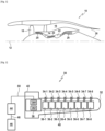
- FIG 2 shows an example of an eight-hole comb for instrumenting an engine in pressure and temperature.
- This comb 30 comprises on the one hand on a central tube 32 of longitudinal axis, associated with each orifice 34-1 to 34-8 pierced in this tube and arranged, preferably regularly, along its longitudinal axis, a measuring sensor 36-1 to 36-8 ensuring for example as illustrated the measurement of the pressure and temperature (P&T) of the gas impacting these orifices and conventionally formed of a mechanical probe and its electronic processing interface (analog/digital adaptation and conversion).
- P&T pressure and temperature
- This communication link 40 makes it possible to guarantee real-time transmission of the measurement values of the measurement sensors in order to allow the turbomachine to be operated reactively.
- the person skilled in the art will be able to determine and adjust the necessary sampling frequency according to the type and number of measurements carried out by the instrumentation comb.
- the measurement values acquired by the sensors in analog form are directly converted at the sensors, by its electronic processing interface, in the form of digital data and are then transmitted to the slave processing unit 38 via the digital communication link 40.
- This digitization is therefore carried out as close as possible to the measurement point, to limit the analog disturbances existing in a harsh environment such as that of an aircraft engine and due, for example, to high temperatures or noise.
- the master processing unit 44 receives the digital data from the collection of sensor measurements and sent by the communication module 380 on a single communication link 50, preferably wired, through a reduced number of wires, advantageously 4 wires, preferably 2 wires.
- This single communication link 50 connects the slave processing unit 38 to the master processing unit 44 and makes it possible both to transfer the data from the sensors and to provide the necessary energy to the slave processing unit 38, more precisely to a power management module 382 of this unit which ensures its own power supply as well as the power supply of the communication module 380 and the measurement sensors 36-1 to 36-8 via the digital communication link 40.
- the number of cables usually existing between the measurement sensors and the test bench is notably reduced.
- THE figures 3 And 4 illustrate a configuration of the invention in which an aircraft engine is instrumented by a plurality of instrumentation combs, each being placed on a fixed radius in one or more planes (Planes P1 and P2 for example) determined of the engine and connected by a communication link to the next comb in order to form a network of combs in the form of one or more circles which can be connected together.
- the number of combs of this network each integrating several measurement sensors is extensible and reconfigurable to adapt to each application.
- the combs are advantageously regularly distributed around the circumference of the engine and a single master processing unit 44 remote from the test bench 46 is sufficient to manage the comb network.
- the comb network (the combs may be different in number of orifices as illustrated) is connected to the master processing unit 44 through a single wired communication link 50 (for example of the Ethernet or RS485 type as mentioned above) as illustrated having a reduced number of wires, advantageously 4 wires, preferably 2 wires.
- This single communication link 50 also makes it possible to connect the different combs together (via the slave processing units 38) in order to transmit, advantageously via a single slave processing unit 38, the digital data from the sensors to the master processing unit 44.
- the comb network is connected to the master processing unit 44 via a single wireless communication link 52 (of the LoRa or WiFi type for example).
- Each of the slave processing units 38 communicates with the slave processing units belonging to the same plane via this single wireless communication link 52, preferably by a wireless transmission/reception system 384, advantageously integrated in the unit 38.
- a slave processing unit of the same plane then transmits to the master processing unit 44 comprising its own wireless transmission/reception system 440 the digital data from the sensors, which can in turn be addressed to the test bench 46 which receives them through its transmission/reception system 460.
- the power supply is provided by the energy management module 382 which preferably comprises an integrated energy source such as a battery or by an energy management module also acting as an energy harvester.
- the invention allows easier implementation of a test bench for instrumenting an aircraft engine in P&T because the measurements are directly converted into digital as close as possible to the measurement point to limit analog disturbances in a harsh environment (HT, noise, etc.) and that only one electronic interface is present on the test bench side.
- the measurement is taken directly at the measurement point and not brought back outside the engine, avoiding any loss due to both internal and external tubular connections.
Landscapes
- Physics & Mathematics (AREA)
- General Physics & Mathematics (AREA)
- Chemical & Material Sciences (AREA)
- Engineering & Computer Science (AREA)
- Combustion & Propulsion (AREA)
- Arrangements For Transmission Of Measured Signals (AREA)
- Testing Or Calibration Of Command Recording Devices (AREA)
- Measuring Fluid Pressure (AREA)
Claims (12)
- Instrumentenkamm für ein Flugzeugtriebwerk, der ein zentrales Rohr (32) mit Längsachse, in das eine bestimmte Anzahl an Öffnungen gebohrt ist, die entlang dieser Längsachse beabstandet sind, und eine Basis (42) beinhaltet, die ein proximales Ende dieses Rohres bildet und dazu bestimmt ist, an einem Teil des Gehäuses des Flugzeugtriebwerks befestigt zu sein, wobei jeder Öffnung eine mechanische Sonde zum Messen eines physikalischen Parameters des Flugzeugtriebwerks zugeordnet ist, wobei jeder mechanischen Sonde eine elektronische Verarbeitungsschnittstelle zugeordnet ist und die Basis eine Slave-Verarbeitungseinheit (38) integriert, die mit jeder der elektronischen Verarbeitungsschnittstellen durch eine digitale Kommunikationsverbindung (40) verbunden ist, die in der Lage ist, in Echtzeit digitale Messdaten zu empfangen, die den physikalischen Parametern entsprechen, die durch die mechanischen Messsonden gemessen werden und dazu bestimmt sind, an eine Master-Verarbeitungseinheit (44) durch eine einzelne Kommunikationsverbindung (50, 52) kommuniziert zu werden,
dadurch gekennzeichnet, dass
die mechanischen Sonden und ihre elektronische Verarbeitungsschnittstelle auf dem zentralen Rohr (32) angeordnet und voneinander entlang der Längsachse des zentralen Rohres (32) beabstandet sind. - Instrumentenkamm nach Anspruch 1, dadurch gekennzeichnet, dass der physikalische Parameter ein beliebiger oder eine Verbindung der folgenden Parameter ist: ein Druck, eine Temperatur, eine Luftfeuchtigkeit oder eine Gaszusammensetzung.
- Instrumentenkamm nach Anspruch 1 oder Anspruch 2, dadurch gekennzeichnet, dass die einzelne Kommunikationsverbindung eine drahtgebundene (50) oder drahtlose (52) Verbindung ist.
- Instrumentenkamm nach Anspruch 3, dadurch gekennzeichnet, dass die drahtgebundene Verbindung vom Typ Ethernet oder RS485 und die drahtlose Verbindung vom Typ LoRa oder WiFi ist.
- Instrumentenkamm nach Anspruch 1 oder Anspruch 2, dadurch gekennzeichnet, dass die Slave-Verarbeitungseinheit (38) ein Versorgungsverwaltungsmodul (382), das ausgelegt ist, um die Versorgung der elektronischen Verarbeitungsschnittstellen mit Energie sicherzustellen, und ein Kommunikationsmodul (380), das die einzelne Kommunikationsverbindung (50) stützt, beinhaltet.
- Kammnetzwerk, das aus mehreren Instrumentenkämmen nach einem der Ansprüche 1 bis 5 gebildet ist, in dem die Instrumentenkämme regelmäßig auf dem Umfang und auf mehreren Ebenen des Flugzeugtriebwerks verteilt sind.
- Kammnetzwerk nach Anspruch 6, dadurch gekennzeichnet, dass die Slave-Verarbeitungseinheiten (38) der Instrumentenkämme einer gleichen Ebene der Reihe nach miteinander verbunden sind, um einen Kreis zu bilden, wobei die einzelne Kommunikationsverbindung (50) mit der Master-Verarbeitungseinheit (44) von höchstens einer bestimmten Slave-Verarbeitungseinheit (38) von einem Instrumentenkamm jeder Ebene des Kammnetzwerks aus erfolgt.
- Kammnetzwerk nach Anspruch 6, dadurch gekennzeichnet, dass die Slave-Verarbeitungseinheit (38) eines bestimmten Instrumentenkamms einer gegebenen Ebene mit einer Slave-Verarbeitungseinheit (38) eines bestimmten Instrumentenkamms einer anderen Ebene verbunden ist.
- System zum Sammeln von Messungen eines physikalischen Parameters eines Flugzeugtriebwerks, umfassend:- mindestens einen Instrumentenkamm (30) nach einem der Ansprüche 1 bis 5,- eine Master-Verarbeitungseinheit (44), die durch eine Kommunikationsverbindung (48) mit einem Prüfstand (46) verbunden ist, wobei die Master-Verarbeitungseinheit (44) mit der Slave-Verarbeitungseinheit (38) des Kamms durch eine einzelne Kommunikationsverbindung (50, 52) verbunden ist, die dazu bestimmt ist, die Slave-Verarbeitungseinheit (38) mit Energie zu versorgen und die Daten, die von den elektronischen Verarbeitungsschnittstellen ausgegeben werden, zu übertragen.
- System nach Anspruch 9, wobei die einzelne Kommunikationsverbindung drahtgebunden (50) oder drahtlos (52) ist und die Kommunikationsverbindung zwischen der Master-Verarbeitungseinheit (44) und dem Prüfstand (46) eine drahtgebundene oder drahtlose (48) Verbindung ist.
- Flugzeugtriebwerk, das mindestens einen Instrumentenkamm nach einem der Ansprüche 1 bis 5 oder ein Kammnetzwerk nach einem der Ansprüche 6 bis 8 beinhaltet.
- Flugzeug, das ein Triebwerk nach Anspruch 11 beinhaltet.
Applications Claiming Priority (2)
| Application Number | Priority Date | Filing Date | Title |
|---|---|---|---|
| FR2012872A FR3117213B1 (fr) | 2020-12-08 | 2020-12-08 | Peigne d’instrumentation pour moteur d’aéronef à capteurs et électronique intégrés |
| PCT/FR2021/052145 WO2022123143A1 (fr) | 2020-12-08 | 2021-11-30 | Peigne d'instrumentation pour moteur d'aeronef a capteurs et electronique integres |
Publications (2)
| Publication Number | Publication Date |
|---|---|
| EP4260040A1 EP4260040A1 (de) | 2023-10-18 |
| EP4260040B1 true EP4260040B1 (de) | 2024-10-16 |
Family
ID=74347375
Family Applications (1)
| Application Number | Title | Priority Date | Filing Date |
|---|---|---|---|
| EP21830718.9A Active EP4260040B1 (de) | 2020-12-08 | 2021-11-30 | Instrumentenkamm für ein flugzeugtriebwerk mit sensoren und integriertem elektronischem system |
Country Status (5)
| Country | Link |
|---|---|
| US (1) | US12566107B2 (de) |
| EP (1) | EP4260040B1 (de) |
| CN (1) | CN116601472A (de) |
| FR (1) | FR3117213B1 (de) |
| WO (1) | WO2022123143A1 (de) |
Families Citing this family (4)
| Publication number | Priority date | Publication date | Assignee | Title |
|---|---|---|---|---|
| FR3145991A1 (fr) * | 2023-02-17 | 2024-08-23 | Airbus | Dispositif électronique pour râteau de mesure facilitant le chargement de données. |
| CN118518248A (zh) | 2023-02-17 | 2024-08-20 | 空中客车运营简化股份公司 | 改进不稳定空气动力学现象监测的压力测量棒 |
| FR3161275B1 (fr) * | 2024-04-12 | 2026-03-06 | Safran Aircraft Engines | Peigne de mesure d’un paramètre d’un gaz, turbomachine ayant le peigne de mesure |
| FR3165070A1 (fr) * | 2024-07-29 | 2026-01-30 | Safran Aircraft Engines | Peigne d’instrumentation numérique |
Family Cites Families (7)
| Publication number | Priority date | Publication date | Assignee | Title |
|---|---|---|---|---|
| US7328623B2 (en) * | 2006-03-20 | 2008-02-12 | General Electric Company | Temperature and/or pressure sensor assembly |
| US8965728B2 (en) * | 2011-05-10 | 2015-02-24 | General Electric Company | Exhaust strut radial temperature measurement |
| US8839662B2 (en) | 2011-06-27 | 2014-09-23 | United Technologies Corporation | Station probe for gas turbine engines |
| JP6378419B2 (ja) * | 2015-03-12 | 2018-08-22 | 株式会社日立製作所 | 機械診断装置および機械診断方法 |
| US10871402B2 (en) * | 2017-03-31 | 2020-12-22 | Safran Aircraft Engines | Device for measuring the characteristics of an air flow |
| US10684183B2 (en) * | 2018-04-24 | 2020-06-16 | The Boeing Company | Powered total pressure measurement rake with telemetry |
| US11630031B2 (en) * | 2021-06-29 | 2023-04-18 | Rolls-Royce North American Technologies Inc. | Engine-mounted instrumentation assembly |
-
2020
- 2020-12-08 FR FR2012872A patent/FR3117213B1/fr active Active
-
2021
- 2021-11-30 US US18/256,595 patent/US12566107B2/en active Active
- 2021-11-30 EP EP21830718.9A patent/EP4260040B1/de active Active
- 2021-11-30 CN CN202180082294.5A patent/CN116601472A/zh active Pending
- 2021-11-30 WO PCT/FR2021/052145 patent/WO2022123143A1/fr not_active Ceased
Also Published As
| Publication number | Publication date |
|---|---|
| FR3117213B1 (fr) | 2024-02-23 |
| EP4260040A1 (de) | 2023-10-18 |
| WO2022123143A1 (fr) | 2022-06-16 |
| FR3117213A1 (fr) | 2022-06-10 |
| CN116601472A (zh) | 2023-08-15 |
| US12566107B2 (en) | 2026-03-03 |
| US20230366783A1 (en) | 2023-11-16 |
Similar Documents
| Publication | Publication Date | Title |
|---|---|---|
| EP4260040B1 (de) | Instrumentenkamm für ein flugzeugtriebwerk mit sensoren und integriertem elektronischem system | |
| US5544478A (en) | Optical sensing of combustion dynamics | |
| EP2577323B1 (de) | Vorrichtung zur aufnahme/verteilung einer flüssigkeit an mehreren stellen, im besonderen eine sonde zur druckmessung am lufteinlass einer turbomaschine | |
| US10775269B2 (en) | Blade health inspection using an excitation actuator and vibration sensor | |
| CA2783222C (fr) | Procede de determination de vitesse air d'un aeronef et aeronef equipe de moyens de mise en oeuvre | |
| US10830132B2 (en) | Micro thermal imaging system for turbine engines | |
| GB2401171A (en) | A system for monitoring and adjusting gas turbine combustion | |
| EP3992929A1 (de) | System und verfahren zur übertragung von motorfehlerdaten | |
| CN109443786A (zh) | 姿轨控发动机燃气阀响应时间及羽流温度测量装置及方法 | |
| EP0153207A1 (de) | Regelanlage für aufgeladene Brennkraftmaschine mit einer Umgehungsleitung und einer zusätzlichen Brennkammer | |
| US20200096331A1 (en) | Anti-rotation method for angled face cap probe | |
| EP4225647A1 (de) | Diagnose einer flugzeugmotorsteuereinheit | |
| EP4058365A1 (de) | Vorrichtung und verfahren zur verwaltung einer flotte von informationskommunikationsvorrichtungen im hinblick auf die aktualisierung eines digitalen zwillings einer turbomaschine | |
| BE1026619B1 (fr) | Systeme de mesure pour turbomachine | |
| FR3127784A1 (fr) | Assemblage comportant deux tronçons tubulaires concentriques et un ensemble de capteurs de flux thermique à l’intérieur du tronçon tubulaire extérieur | |
| FR2997508A1 (fr) | Harnais et cable comportant une pluralite de capteurs elementaires et procede de surveillance d'un cable et d'un harnais | |
| CN209182233U (zh) | 一种炉内多维燃烧气体温度和多组分浓度测量系统 | |
| US11946811B2 (en) | Non-contact high temperature measurement system | |
| CN113945354B (zh) | 一种用于辨识膨胀风洞加速段流动分区特性的试验方法 | |
| CN216050701U (zh) | 一种航空发动机加力故障检测系统 | |
| EP3967851A1 (de) | Gasturbinentriebwerk mit luftströmungsmesssystem | |
| FR3103893A1 (fr) | Système et procédé d’identification de paramètres d’un capteur fixé sur un carter | |
| US20230313700A1 (en) | Monitoring fluid consumption of gas turbine engine during an engine cycle | |
| RO126438B1 (ro) | Sistem de achiziţie şi prelucrare automată a parametrilor motoarelor turboreactoare | |
| WO2025242987A1 (fr) | Procédé préventif de surveillance thermique d'une structure interne fixe dans une nacelle de turbomachine d'aéronef |
Legal Events
| Date | Code | Title | Description |
|---|---|---|---|
| STAA | Information on the status of an ep patent application or granted ep patent |
Free format text: STATUS: UNKNOWN |
|
| STAA | Information on the status of an ep patent application or granted ep patent |
Free format text: STATUS: THE INTERNATIONAL PUBLICATION HAS BEEN MADE |
|
| PUAI | Public reference made under article 153(3) epc to a published international application that has entered the european phase |
Free format text: ORIGINAL CODE: 0009012 |
|
| STAA | Information on the status of an ep patent application or granted ep patent |
Free format text: STATUS: REQUEST FOR EXAMINATION WAS MADE |
|
| 17P | Request for examination filed |
Effective date: 20230623 |
|
| AK | Designated contracting states |
Kind code of ref document: A1 Designated state(s): AL AT BE BG CH CY CZ DE DK EE ES FI FR GB GR HR HU IE IS IT LI LT LU LV MC MK MT NL NO PL PT RO RS SE SI SK SM TR |
|
| DAV | Request for validation of the european patent (deleted) | ||
| DAX | Request for extension of the european patent (deleted) | ||
| GRAP | Despatch of communication of intention to grant a patent |
Free format text: ORIGINAL CODE: EPIDOSNIGR1 |
|
| STAA | Information on the status of an ep patent application or granted ep patent |
Free format text: STATUS: GRANT OF PATENT IS INTENDED |
|
| INTG | Intention to grant announced |
Effective date: 20240613 |
|
| GRAS | Grant fee paid |
Free format text: ORIGINAL CODE: EPIDOSNIGR3 |
|
| GRAA | (expected) grant |
Free format text: ORIGINAL CODE: 0009210 |
|
| STAA | Information on the status of an ep patent application or granted ep patent |
Free format text: STATUS: THE PATENT HAS BEEN GRANTED |
|
| AK | Designated contracting states |
Kind code of ref document: B1 Designated state(s): AL AT BE BG CH CY CZ DE DK EE ES FI FR GB GR HR HU IE IS IT LI LT LU LV MC MK MT NL NO PL PT RO RS SE SI SK SM TR |
|
| REG | Reference to a national code |
Ref country code: GB Ref legal event code: FG4D Free format text: NOT ENGLISH |
|
| REG | Reference to a national code |
Ref country code: CH Ref legal event code: EP |
|
| REG | Reference to a national code |
Ref country code: IE Ref legal event code: FG4D Free format text: LANGUAGE OF EP DOCUMENT: FRENCH |
|
| REG | Reference to a national code |
Ref country code: DE Ref legal event code: R096 Ref document number: 602021020466 Country of ref document: DE |
|
| REG | Reference to a national code |
Ref country code: LT Ref legal event code: MG9D |
|
| REG | Reference to a national code |
Ref country code: NL Ref legal event code: MP Effective date: 20241016 |
|
| REG | Reference to a national code |
Ref country code: AT Ref legal event code: MK05 Ref document number: 1733273 Country of ref document: AT Kind code of ref document: T Effective date: 20241016 |
|
| PG25 | Lapsed in a contracting state [announced via postgrant information from national office to epo] |
Ref country code: NL Free format text: LAPSE BECAUSE OF FAILURE TO SUBMIT A TRANSLATION OF THE DESCRIPTION OR TO PAY THE FEE WITHIN THE PRESCRIBED TIME-LIMIT Effective date: 20241016 |
|
| PG25 | Lapsed in a contracting state [announced via postgrant information from national office to epo] |
Ref country code: NL Free format text: LAPSE BECAUSE OF FAILURE TO SUBMIT A TRANSLATION OF THE DESCRIPTION OR TO PAY THE FEE WITHIN THE PRESCRIBED TIME-LIMIT Effective date: 20241016 |
|
| PG25 | Lapsed in a contracting state [announced via postgrant information from national office to epo] |
Ref country code: IS Free format text: LAPSE BECAUSE OF FAILURE TO SUBMIT A TRANSLATION OF THE DESCRIPTION OR TO PAY THE FEE WITHIN THE PRESCRIBED TIME-LIMIT Effective date: 20250216 Ref country code: HR Free format text: LAPSE BECAUSE OF FAILURE TO SUBMIT A TRANSLATION OF THE DESCRIPTION OR TO PAY THE FEE WITHIN THE PRESCRIBED TIME-LIMIT Effective date: 20241016 Ref country code: PT Free format text: LAPSE BECAUSE OF FAILURE TO SUBMIT A TRANSLATION OF THE DESCRIPTION OR TO PAY THE FEE WITHIN THE PRESCRIBED TIME-LIMIT Effective date: 20250217 |
|
| PG25 | Lapsed in a contracting state [announced via postgrant information from national office to epo] |
Ref country code: FI Free format text: LAPSE BECAUSE OF FAILURE TO SUBMIT A TRANSLATION OF THE DESCRIPTION OR TO PAY THE FEE WITHIN THE PRESCRIBED TIME-LIMIT Effective date: 20241016 |
|
| PG25 | Lapsed in a contracting state [announced via postgrant information from national office to epo] |
Ref country code: BG Free format text: LAPSE BECAUSE OF FAILURE TO SUBMIT A TRANSLATION OF THE DESCRIPTION OR TO PAY THE FEE WITHIN THE PRESCRIBED TIME-LIMIT Effective date: 20241016 |
|
| PG25 | Lapsed in a contracting state [announced via postgrant information from national office to epo] |
Ref country code: ES Free format text: LAPSE BECAUSE OF FAILURE TO SUBMIT A TRANSLATION OF THE DESCRIPTION OR TO PAY THE FEE WITHIN THE PRESCRIBED TIME-LIMIT Effective date: 20241016 |
|
| PG25 | Lapsed in a contracting state [announced via postgrant information from national office to epo] |
Ref country code: NO Free format text: LAPSE BECAUSE OF FAILURE TO SUBMIT A TRANSLATION OF THE DESCRIPTION OR TO PAY THE FEE WITHIN THE PRESCRIBED TIME-LIMIT Effective date: 20250116 |
|
| PG25 | Lapsed in a contracting state [announced via postgrant information from national office to epo] |
Ref country code: AT Free format text: LAPSE BECAUSE OF FAILURE TO SUBMIT A TRANSLATION OF THE DESCRIPTION OR TO PAY THE FEE WITHIN THE PRESCRIBED TIME-LIMIT Effective date: 20241016 Ref country code: GR Free format text: LAPSE BECAUSE OF FAILURE TO SUBMIT A TRANSLATION OF THE DESCRIPTION OR TO PAY THE FEE WITHIN THE PRESCRIBED TIME-LIMIT Effective date: 20250117 Ref country code: LV Free format text: LAPSE BECAUSE OF FAILURE TO SUBMIT A TRANSLATION OF THE DESCRIPTION OR TO PAY THE FEE WITHIN THE PRESCRIBED TIME-LIMIT Effective date: 20241016 |
|
| PG25 | Lapsed in a contracting state [announced via postgrant information from national office to epo] |
Ref country code: PL Free format text: LAPSE BECAUSE OF FAILURE TO SUBMIT A TRANSLATION OF THE DESCRIPTION OR TO PAY THE FEE WITHIN THE PRESCRIBED TIME-LIMIT Effective date: 20241016 |
|
| PG25 | Lapsed in a contracting state [announced via postgrant information from national office to epo] |
Ref country code: RS Free format text: LAPSE BECAUSE OF FAILURE TO SUBMIT A TRANSLATION OF THE DESCRIPTION OR TO PAY THE FEE WITHIN THE PRESCRIBED TIME-LIMIT Effective date: 20250116 |
|
| REG | Reference to a national code |
Ref country code: CH Ref legal event code: PL |
|
| PG25 | Lapsed in a contracting state [announced via postgrant information from national office to epo] |
Ref country code: SM Free format text: LAPSE BECAUSE OF FAILURE TO SUBMIT A TRANSLATION OF THE DESCRIPTION OR TO PAY THE FEE WITHIN THE PRESCRIBED TIME-LIMIT Effective date: 20241016 |
|
| PG25 | Lapsed in a contracting state [announced via postgrant information from national office to epo] |
Ref country code: MC Free format text: LAPSE BECAUSE OF FAILURE TO SUBMIT A TRANSLATION OF THE DESCRIPTION OR TO PAY THE FEE WITHIN THE PRESCRIBED TIME-LIMIT Effective date: 20241016 |
|
| PG25 | Lapsed in a contracting state [announced via postgrant information from national office to epo] |
Ref country code: DK Free format text: LAPSE BECAUSE OF FAILURE TO SUBMIT A TRANSLATION OF THE DESCRIPTION OR TO PAY THE FEE WITHIN THE PRESCRIBED TIME-LIMIT Effective date: 20241016 |
|
| PG25 | Lapsed in a contracting state [announced via postgrant information from national office to epo] |
Ref country code: LU Free format text: LAPSE BECAUSE OF NON-PAYMENT OF DUE FEES Effective date: 20241130 |
|
| REG | Reference to a national code |
Ref country code: CH Ref legal event code: PL |
|
| REG | Reference to a national code |
Ref country code: DE Ref legal event code: R097 Ref document number: 602021020466 Country of ref document: DE |
|
| PG25 | Lapsed in a contracting state [announced via postgrant information from national office to epo] |
Ref country code: EE Free format text: LAPSE BECAUSE OF FAILURE TO SUBMIT A TRANSLATION OF THE DESCRIPTION OR TO PAY THE FEE WITHIN THE PRESCRIBED TIME-LIMIT Effective date: 20241016 |
|
| PG25 | Lapsed in a contracting state [announced via postgrant information from national office to epo] |
Ref country code: CH Free format text: LAPSE BECAUSE OF NON-PAYMENT OF DUE FEES Effective date: 20241130 |
|
| PG25 | Lapsed in a contracting state [announced via postgrant information from national office to epo] |
Ref country code: RO Free format text: LAPSE BECAUSE OF FAILURE TO SUBMIT A TRANSLATION OF THE DESCRIPTION OR TO PAY THE FEE WITHIN THE PRESCRIBED TIME-LIMIT Effective date: 20241016 |
|
| PG25 | Lapsed in a contracting state [announced via postgrant information from national office to epo] |
Ref country code: SK Free format text: LAPSE BECAUSE OF FAILURE TO SUBMIT A TRANSLATION OF THE DESCRIPTION OR TO PAY THE FEE WITHIN THE PRESCRIBED TIME-LIMIT Effective date: 20241016 |
|
| PG25 | Lapsed in a contracting state [announced via postgrant information from national office to epo] |
Ref country code: CZ Free format text: LAPSE BECAUSE OF FAILURE TO SUBMIT A TRANSLATION OF THE DESCRIPTION OR TO PAY THE FEE WITHIN THE PRESCRIBED TIME-LIMIT Effective date: 20241016 |
|
| PG25 | Lapsed in a contracting state [announced via postgrant information from national office to epo] |
Ref country code: IT Free format text: LAPSE BECAUSE OF FAILURE TO SUBMIT A TRANSLATION OF THE DESCRIPTION OR TO PAY THE FEE WITHIN THE PRESCRIBED TIME-LIMIT Effective date: 20241016 |
|
| PLBE | No opposition filed within time limit |
Free format text: ORIGINAL CODE: 0009261 |
|
| STAA | Information on the status of an ep patent application or granted ep patent |
Free format text: STATUS: NO OPPOSITION FILED WITHIN TIME LIMIT |
|
| REG | Reference to a national code |
Ref country code: BE Ref legal event code: MM Effective date: 20241130 |
|
| PG25 | Lapsed in a contracting state [announced via postgrant information from national office to epo] |
Ref country code: SE Free format text: LAPSE BECAUSE OF FAILURE TO SUBMIT A TRANSLATION OF THE DESCRIPTION OR TO PAY THE FEE WITHIN THE PRESCRIBED TIME-LIMIT Effective date: 20241016 |
|
| 26N | No opposition filed |
Effective date: 20250717 |
|
| PG25 | Lapsed in a contracting state [announced via postgrant information from national office to epo] |
Ref country code: BE Free format text: LAPSE BECAUSE OF NON-PAYMENT OF DUE FEES Effective date: 20241130 |
|
| PG25 | Lapsed in a contracting state [announced via postgrant information from national office to epo] |
Ref country code: IE Free format text: LAPSE BECAUSE OF NON-PAYMENT OF DUE FEES Effective date: 20241130 |
|
| PGFP | Annual fee paid to national office [announced via postgrant information from national office to epo] |
Ref country code: DE Payment date: 20251118 Year of fee payment: 5 |
|
| PGFP | Annual fee paid to national office [announced via postgrant information from national office to epo] |
Ref country code: GB Payment date: 20251125 Year of fee payment: 5 |
|
| PGFP | Annual fee paid to national office [announced via postgrant information from national office to epo] |
Ref country code: FR Payment date: 20251125 Year of fee payment: 5 |