EP4259922B1 - Engine system with coolant collector bracket between cylinder head and egr cooler - Google Patents
Engine system with coolant collector bracket between cylinder head and egr cooler Download PDFInfo
- Publication number
- EP4259922B1 EP4259922B1 EP21820038.4A EP21820038A EP4259922B1 EP 4259922 B1 EP4259922 B1 EP 4259922B1 EP 21820038 A EP21820038 A EP 21820038A EP 4259922 B1 EP4259922 B1 EP 4259922B1
- Authority
- EP
- European Patent Office
- Prior art keywords
- coolant
- collector bracket
- cylinder head
- internal
- egr
- Prior art date
- Legal status (The legal status is an assumption and is not a legal conclusion. Google has not performed a legal analysis and makes no representation as to the accuracy of the status listed.)
- Active
Links
Images






Classifications
-
- F—MECHANICAL ENGINEERING; LIGHTING; HEATING; WEAPONS; BLASTING
- F02—COMBUSTION ENGINES; HOT-GAS OR COMBUSTION-PRODUCT ENGINE PLANTS
- F02M—SUPPLYING COMBUSTION ENGINES IN GENERAL WITH COMBUSTIBLE MIXTURES OR CONSTITUENTS THEREOF
- F02M26/00—Engine-pertinent apparatus for adding exhaust gases to combustion-air, main fuel or fuel-air mixture, e.g. by exhaust gas recirculation [EGR] systems
- F02M26/13—Arrangement or layout of EGR passages, e.g. in relation to specific engine parts or for incorporation of accessories
- F02M26/22—Arrangement or layout of EGR passages, e.g. in relation to specific engine parts or for incorporation of accessories with coolers in the recirculation passage
- F02M26/29—Constructional details of the coolers, e.g. pipes, plates, ribs, insulation or materials
- F02M26/30—Connections of coolers to other devices, e.g. to valves, heaters, compressors or filters; Coolers characterised by their location on the engine
-
- F—MECHANICAL ENGINEERING; LIGHTING; HEATING; WEAPONS; BLASTING
- F01—MACHINES OR ENGINES IN GENERAL; ENGINE PLANTS IN GENERAL; STEAM ENGINES
- F01P—COOLING OF MACHINES OR ENGINES IN GENERAL; COOLING OF INTERNAL-COMBUSTION ENGINES
- F01P3/00—Liquid cooling
- F01P3/18—Arrangements or mounting of liquid-to-air heat-exchangers
-
- F—MECHANICAL ENGINEERING; LIGHTING; HEATING; WEAPONS; BLASTING
- F01—MACHINES OR ENGINES IN GENERAL; ENGINE PLANTS IN GENERAL; STEAM ENGINES
- F01P—COOLING OF MACHINES OR ENGINES IN GENERAL; COOLING OF INTERNAL-COMBUSTION ENGINES
- F01P3/00—Liquid cooling
- F01P3/02—Arrangements for cooling cylinders or cylinder heads
-
- F—MECHANICAL ENGINEERING; LIGHTING; HEATING; WEAPONS; BLASTING
- F01—MACHINES OR ENGINES IN GENERAL; ENGINE PLANTS IN GENERAL; STEAM ENGINES
- F01P—COOLING OF MACHINES OR ENGINES IN GENERAL; COOLING OF INTERNAL-COMBUSTION ENGINES
- F01P3/00—Liquid cooling
- F01P3/12—Arrangements for cooling other engine or machine parts
-
- F—MECHANICAL ENGINEERING; LIGHTING; HEATING; WEAPONS; BLASTING
- F02—COMBUSTION ENGINES; HOT-GAS OR COMBUSTION-PRODUCT ENGINE PLANTS
- F02F—CYLINDERS, PISTONS OR CASINGS, FOR COMBUSTION ENGINES; ARRANGEMENTS OF SEALINGS IN COMBUSTION ENGINES
- F02F1/00—Cylinders; Cylinder heads
- F02F1/02—Cylinders; Cylinder heads having cooling means
- F02F1/10—Cylinders; Cylinder heads having cooling means for liquid cooling
-
- F—MECHANICAL ENGINEERING; LIGHTING; HEATING; WEAPONS; BLASTING
- F02—COMBUSTION ENGINES; HOT-GAS OR COMBUSTION-PRODUCT ENGINE PLANTS
- F02F—CYLINDERS, PISTONS OR CASINGS, FOR COMBUSTION ENGINES; ARRANGEMENTS OF SEALINGS IN COMBUSTION ENGINES
- F02F7/00—Casings, e.g. crankcases
- F02F7/0021—Construction
-
- F—MECHANICAL ENGINEERING; LIGHTING; HEATING; WEAPONS; BLASTING
- F02—COMBUSTION ENGINES; HOT-GAS OR COMBUSTION-PRODUCT ENGINE PLANTS
- F02M—SUPPLYING COMBUSTION ENGINES IN GENERAL WITH COMBUSTIBLE MIXTURES OR CONSTITUENTS THEREOF
- F02M26/00—Engine-pertinent apparatus for adding exhaust gases to combustion-air, main fuel or fuel-air mixture, e.g. by exhaust gas recirculation [EGR] systems
- F02M26/13—Arrangement or layout of EGR passages, e.g. in relation to specific engine parts or for incorporation of accessories
- F02M26/22—Arrangement or layout of EGR passages, e.g. in relation to specific engine parts or for incorporation of accessories with coolers in the recirculation passage
-
- F—MECHANICAL ENGINEERING; LIGHTING; HEATING; WEAPONS; BLASTING
- F02—COMBUSTION ENGINES; HOT-GAS OR COMBUSTION-PRODUCT ENGINE PLANTS
- F02M—SUPPLYING COMBUSTION ENGINES IN GENERAL WITH COMBUSTIBLE MIXTURES OR CONSTITUENTS THEREOF
- F02M26/00—Engine-pertinent apparatus for adding exhaust gases to combustion-air, main fuel or fuel-air mixture, e.g. by exhaust gas recirculation [EGR] systems
- F02M26/13—Arrangement or layout of EGR passages, e.g. in relation to specific engine parts or for incorporation of accessories
- F02M26/22—Arrangement or layout of EGR passages, e.g. in relation to specific engine parts or for incorporation of accessories with coolers in the recirculation passage
- F02M26/23—Layout, e.g. schematics
-
- F—MECHANICAL ENGINEERING; LIGHTING; HEATING; WEAPONS; BLASTING
- F02—COMBUSTION ENGINES; HOT-GAS OR COMBUSTION-PRODUCT ENGINE PLANTS
- F02M—SUPPLYING COMBUSTION ENGINES IN GENERAL WITH COMBUSTIBLE MIXTURES OR CONSTITUENTS THEREOF
- F02M26/00—Engine-pertinent apparatus for adding exhaust gases to combustion-air, main fuel or fuel-air mixture, e.g. by exhaust gas recirculation [EGR] systems
- F02M26/13—Arrangement or layout of EGR passages, e.g. in relation to specific engine parts or for incorporation of accessories
- F02M26/22—Arrangement or layout of EGR passages, e.g. in relation to specific engine parts or for incorporation of accessories with coolers in the recirculation passage
- F02M26/29—Constructional details of the coolers, e.g. pipes, plates, ribs, insulation or materials
- F02M26/32—Liquid-cooled heat exchangers
-
- F—MECHANICAL ENGINEERING; LIGHTING; HEATING; WEAPONS; BLASTING
- F01—MACHINES OR ENGINES IN GENERAL; ENGINE PLANTS IN GENERAL; STEAM ENGINES
- F01P—COOLING OF MACHINES OR ENGINES IN GENERAL; COOLING OF INTERNAL-COMBUSTION ENGINES
- F01P11/00—Component parts, details, or accessories not provided for in, or of interest apart from, groups F01P1/00 - F01P9/00
- F01P11/04—Arrangements of liquid pipes or hoses
-
- F—MECHANICAL ENGINEERING; LIGHTING; HEATING; WEAPONS; BLASTING
- F01—MACHINES OR ENGINES IN GENERAL; ENGINE PLANTS IN GENERAL; STEAM ENGINES
- F01P—COOLING OF MACHINES OR ENGINES IN GENERAL; COOLING OF INTERNAL-COMBUSTION ENGINES
- F01P3/00—Liquid cooling
- F01P3/02—Arrangements for cooling cylinders or cylinder heads
- F01P2003/028—Cooling cylinders and cylinder heads in series
-
- F—MECHANICAL ENGINEERING; LIGHTING; HEATING; WEAPONS; BLASTING
- F01—MACHINES OR ENGINES IN GENERAL; ENGINE PLANTS IN GENERAL; STEAM ENGINES
- F01P—COOLING OF MACHINES OR ENGINES IN GENERAL; COOLING OF INTERNAL-COMBUSTION ENGINES
- F01P2060/00—Cooling circuits using auxiliaries
- F01P2060/16—Outlet manifold
Definitions
- This disclosure relates generally to an engine system, and more specifically, to an engine system having a coolant collector associated with an exhaust gas recirculation (EGR) cooler.
- EGR exhaust gas recirculation
- a conventional coolant system for an internal combustion engine may include a coolant pump that pumps coolant into a coolant jacket of an engine block of the engine. The coolant then flows longitudinally through a portion of the coolant jacket surrounding the cylinders of the engine. The engine cylinders are cooled by the passing coolant through passages located in or adjacent the cylinder walls. The coolant may then flow into a water jacket of one or more cylinder heads to cool the components of the cylinder heads, such as injectors and valves, and then exits the engine.
- the coolant system may also include a number of other components, such as for example, a radiator, a thermostat, an exhaust gas recirculation (EGR) cooler, an aftercooler, and an oil cooler.
- EGR exhaust gas recirculation
- U.S. Pat. No. 7,516,737 discloses an internal combustion engine with a cooling system and an exhaust gas recirculation (EGR) system.
- the EGR system includes an EGR heat exchanger or cooler with a coolant inlet opening connected to a coolant outlet opening of the engine for receiving coolant therefrom.
- the engine further includes a coolant collecting rail mounted to the engine and having a coolant inlet opening connected to the EGR heat exchanger, and at least one other coolant inlet opening in communication directly with at least one other coolant outlet opening of the engine.
- the cooling system of the '737 patent may have drawbacks both in one or more of manufacturing, assembly, cooling, and serviceability.
- an internal combustion engine system including a cylinder block, a cylinder head attached to the cylinder block, an EGR cooler, and a coolant collector bracket.
- the cylinder head includes a plurality of coolant passages.
- the coolant collector bracket is coupled to and between the cylinder head and the EGR cooler.
- the coolant collector bracket includes a plurality of coolant inlets directly coupled to a plurality of outlets of the plurality of coolant passages of the cylinder head.
- the coolant collector bracket also includes an EGR coolant outlet directly coupled to an inlet of the EGR cooler.
- the coolant collector bracket also includes an EGR coolant inlet directly coupled to an outlet of the EGR cooler.
- a first internal coolant channel is in fluid communication with the plurality of coolant passages of the cylinder head; and a second internal coolant channel in fluid communication with the cylinder block.
- the first internal coolant channel is fluidly separate from the second internal coolant channel, the first and second internal coolant channels fluidly coupling different inlets and outlets.
- an internal combustion engine system including a cylinder block, a cylinder head, an EGR cooler, and a coolant collector bracket.
- the cylinder head is vertically attached to the cylinder block and includes a plurality of coolant passages.
- the EGR cooler includes a plurality of mounting posts.
- the coolant collector bracket is directly coupled to and between the cylinder head and the EGR cooler.
- the coolant collector bracket is aligned to vertically support the EGR cooler.
- the coolant collector bracket includes a first internal channel for directly receiving coolant from a plurality of outlets of the plurality of coolant passages of the cylinder head.
- the coolant collector bracket also includes a second internal channel for directly communicating the coolant to the cylinder block.
- the coolant collector bracket is directly connected to the EGR cooler at the plurality of mounting posts.
- the first internal coolant channel is fluidly separate from the second internal coolant channel, the first and second internal coolant channels fluidly coupling different inlets and outlets.
- a method of directing coolant flow through an internal combustion engine system includes a cylinder block, a cylinder head attached to the cylinder block, an EGR cooler, and a coolant collector bracket coupled to and between the cylinder head and the EGR cooler.
- the method includes directly supplying coolant through a plurality of outlets of a plurality of coolant passages of the cylinder head and into a plurality of coolant inlets of the coolant collector bracket.
- the method also includes moving the coolant through the plurality of coolant inlets and into a first internal coolant channel of the coolant collector bracket.
- the method also includes directing the coolant to flow upstream through an EGR coolant outlet of the coolant collector bracket and into an inlet of the EGR cooler.
- the method also includes enabling the coolant to flow downstream from an outlet of the EGR cooler and into a second internal coolant channel of the coolant collector bracket to supply the coolant to the cylinder block.
- the first internal coolant channel is fluidly separate from the second internal coolant channel, the first and second internal coolant channels fluidly coupling different inlets and outlets.
- an exemplary embodiment of an internal combustion engine system 10 such as a diesel engine
- the engine system 10 may provide power to various types of applications and/or machines.
- the engine system 10 may power marine and military engines and/or a machine such as an off-highway truck, a railway locomotive, or an earth-moving machine, such as a wheel loader, excavator, dump truck, backhoe, motor grader, material handler, or the like.
- the term "machine” can also refer to stationary equipment like a generator that is driven by the engine system 10 to generate electricity.
- the engine system 10 includes a cylinder block 12, a cylinder head 14 attached to the top of cylinder block 12, an EGR cooler 16, a coolant collector bracket 18, and an exhaust manifold 20, as is known in the art.
- the cylinder block 12, cylinder head 14, EGR cooler 16, and exhaust manifold may be of any appropriate design, e.g. inline or V engine, any number of cylinders, and any fuel type - diesel, gasoline, and/or gaseous fuel.
- FIG. 2 shows the engine system 10 with the exhaust manifold 20 removed, to better view the coolant collector bracket 18. With the exhaust manifold 20 removed, individual cylinder exhaust passages 15 can be seen.
- the cylinder block 12 and cylinder head 14 may further include a plurality of internal coolant passages or sumps (not shown) as part of a coolant circuit to cool the engine system 10.
- the coolant circuit can take any appropriate form, and may include, for example, a coolant sump, one or more coolant pumps, and a radiator or similar device (not shown).
- the EGR cooler 16 forms a portion of the EGR flow path and includes a generally cylindrical-shaped heat exchanger having an EGR inlet end 17 and outlet end 19.
- EGR cooler 16 may be of any appropriate type, such as a parallel tube or parallel flow heat exchanger having a coolant inlet at one end, and a coolant exit at an opposite end. In some embodiments, EGR cooler 16 may have a rectangular, oval, and/or asymmetrical shape.
- EGR cooler 16 may include a plurality of mounting posts 30 for connecting the EGR cooler 16 to a top portion of the coolant collector bracket 18.
- the EGR cooler 16 may include four mounting posts 30, only two of which can be seen in FIGs. 1 and 2 .
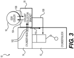
- FIG. 3 schematically depicts an end view of engine system 10. As shown, coolant collector bracket 18 may be secured to a side of the cylinder head 14, and the EGR cooler 16 is secured to a top of the coolant collector bracket 18. FIG. 3 also depicts the coolant path through coolant collector bracket 18 and EGR cooler 16.
- arrow 110 shows the flow of coolant from cylinder head 14 to cylinder block 12 to illustrate a top-down flow of coolant from cylinder head 14 to cylinder block 12;
- arrows 102 depict coolant flow from the cylinder head 14 to the coolant collector bracket 18;
- arrow 104 shows the coolant flow from the coolant collector bracket 18 to the EGR cooler;
- arrow 106 shows the coolant flow from the EGR cooler 16 back into the coolant collector bracket 18;
- arrow 108 shows the coolant flowing from coolant collector bracket 18 back to cylinder block 12.
- the coolant in coolant collector bracket 18 flows to a casted-in collector rail (not shown) in cylinder block 12.
- This collector rail is a cylinder block configured to receive coolant from coolant collector bracket 18.
- FIGs. 4-8 depict the coolant collector bracket 18 alone, removed from the engine system 10.
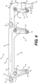
- coolant collector bracket 18 includes a longitudinally extending body portion 80, a plurality of mounting members or mounting legs 31, and an exit leg (e.g., an arm) 39.
- Body portion 80 is mounted to cylinder head 14 to be orientated generally horizontal and includes a longitudinal length approximately the same as the longitudinal length of EGR cooler 16.
- Body portion 80 may include a top portion 82 on which the EGR cooler 16 may be directly secured, and a bottom portion 84 from which mounting legs 31 extend. Referring to FIG.
- the top portion 82 of coolant collector bracket 18 is generally planar and may include a pair of EGR cooler mounts 86, an EGR coolant outlet 36, and an EGR coolant inlet 38.
- Each mount 86 may be similarly configured and one mount 87 may be located at a front end portion 91 of the coolant collector bracket 18, and the other mount 89 may be located at a rear end portion 93 of the coolant collector bracket 18, but not as rear as the exit leg 39.
- the mounts 86 may each extend from the front and rear sides of the body portion 80 generally normal to the longitudinal length of the body portion 80. Mounts 86 may each protrude from sides of the body portion 80 to form a widest extent of the coolant collector bracket 18.
- Mounts 86 may further include a pair of fastener connectors 50 (e.g. threaded or non-threaded bolt receiving holes) at the longitudinal ends of the mounts 86, and such fastener connectors 50 may be located to align and mate with the mounting posts 30 of the EGR cooler 16 ( FIG. 1 ).
- Mounting posts 30 allow for the use of standard coolant face seal(s) and provides a more robust attachment between EGR cooler 16 and coolant collector bracket 18.
- EGR coolant outlet 36 may be located along the longitudinal axis of front mount 87, and generally centrally positioned between the fastener connectors 50 of front mount 87.
- EGR coolant inlet 38 of coolant collector bracket 18 may similarly be located along the longitudinal axis of rear mount 89, and generally centrally positioned between the fastener connectors 50 of the rear mount 89.
- EGR coolant outlet 36 and EGR coolant inlet 38 generally align with each other along the longitudinal direction of the body portion 80.
- EGR coolant outlet 36 and EGR coolant inlet 38 are also located to align with a coolant inlet and coolant outlet, respectively, of EGR cooler 16 (not shown).
- EGR coolant outlet 36 and EGR coolant inlet 38 of coolant collector bracket 18 may include O-ring and/or other appropriate seals.
- the seals may be different between the EGR coolant outlet 36 and EGR coolant inlet 38, such as a radial O-ring seal at EGR coolant outlet 36, and a face seal 103 at EGR coolant inlet 38. Such different seals may facilitate possible misalignment between flow connections between the EGR cooler 16 and the coolant collector bracket 18.
- the coolant inlet of the EGR cooler 16 may include a short tube configured to be inserted into a recess 105 formed in EGR coolant outlet 36 of the coolant collector bracket 18, and such a short tube may be omitted from the coolant outlet of the EGR cooler 16.
- coolant collector bracket 18 may include three mounting legs 31.
- coolant collector bracket 18 may include a front mounting leg 33, a middle mounting leg 35, and a rear mounting leg 37.
- the middle mounting leg 35 may be positioned closer to the rear end portion 93 of the coolant collector bracket 18 such that a distance or gap between the front mounting leg 33 and the middle mounting leg 35 is greater than a distance or gap between the middle mounting leg 35 and the rear mounting leg 37.
- rear mounting leg 37 may be located forward of exit leg 39. It is understood that coolant collector bracket 18 may include more or less mounting legs 31, and the mounting legs 31 may be located at different positions than depicted in the figures.
- Mounting legs 31 may each include a plurality of fastener connectors for connecting the coolant collector bracket 18 to the cylinder head 14.
- the fastener connectors may be similarly arranged on each of the mounting legs 31.
- the fastener connectors may include a top fastener connector 53, and a bottom fastener connector 55.
- the top fastener connector 53 may be located adjacent a junction or transition between body portion 80 and front mounting leg 33.
- Top fastener connector 53 may include a generally round, threaded or non-threaded opening extending transversely through front mounting leg 33 from a front surface to a back surface of thereof. It is understood that the top fastener connector 53 may take different shapes than round.
- Bottom fastener connector 55 may be located at a distal-most end of the front mounting leg 33, and may include a round opening that includes a bottom gap or slot 57 extending the opening through a bottom most surface of front mounting leg 33. With such a bottom slot 57, bottom fastener connector 55 may form a generally C-shape. As will be discussed in more detail below, bottom fastener connector 55 (and corresponding bottom fastener connectors of the other mounting legs 31) facilitates mounting the coolant collector bracket 18 to cylinder head 14. Both top and bottom fastener connectors 53 and 55 are sized and configured for receiving appropriate fasteners, such as cylinder head fasteners (e.g., cylinder head bolts) 52 (included in middle and rear mounting legs 35 and 37 in FIGs. 4 and 5 . As noted above, each of the mounting legs 31 may be provided with the same mounting connector arrangement as front mounting leg 33 discussed above. However, it is understood that different arrangements are contemplated for front mounting leg 33 or any of the other mounting legs 31.
- the back side of mounting legs 31 may be generally similarly arranged and include a generally planar mounting surface 41, and a coolant inlet 43.
- the mounting surfaces 41 of each of the mounting legs 31 are generally coplanar and form the back-most extent of coolant collector bracket 18.
- Coolant inlets 43 may be located between top and bottom fastener connectors 53 and 55, generally above a longitudinal midpoint of mounting legs 31. Coolant inlets 43 are located to align with coolant outlets 34 of the cylinder head 14 ( FIG. 13 ).
- the distance between each coolant inlet 43 may be substantially different based on the position of and distance between mounting legs 31. As shown in FIG. 5 , the distance between coolant inlet 43 of front mounting leg 33 and coolant inlet 43 of each of the other mounting legs 31 may be different.
- FIG. 5 shows middle mounting leg 35 and rear mounting leg 37 with a gasket 58 mounted to the planar mounting surface 41 of the mounting legs 31.
- the particulars of the mounting gaskets 58 are further shown in FIGs. 10-12 .
- FIG. 10 illustrates a front view
- FIG. 11 illustrates a rear view of a gasket 58.
- gaskets 58 are securely fastened to the mounting legs 31 of the coolant collector bracket 18.
- each gasket 58 is sized and shaped to snap onto a surface of a corresponding mounting leg 31.
- the gaskets 58 are configured to directly couple to the first side 26 of the cylinder head 14.
- each gasket 58 includes an inlet opening 60 corresponding to a respective coolant inlet 43 ( FIG. 5 ).
- each gasket 58 includes a pair of flanges 68 that extend laterally to engage surface edges of a corresponding mounting leg 31.
- the gaskets 58 are of a metal material.
- the cylinder head 14 includes a plurality of bottom fasteners 66 (e.g., bolts) positioned along a bottom edge of the first side 26.
- the cylinder head 14 also includes a plurality of bracket connection openings 70 configured to receive the cylinder head fasteners 52 associated with corresponding mounting legs 31.
- exit leg (e.g., arm) 39 forms a generally L-shape extending from the rear end portion 93 of coolant collector bracket 18.
- the exit leg 39 includes a protrusion forming a seat (e.g., a flap) 54 that extends upwards from the exit leg 39 such that the seat 54 laterally protrudes from the top side 48.
- the exit leg 39 includes a distal end 45 that is coupled to a jumper tube 56.
- the distal end 45 of exit leg 39 extends generally orthogonally from the body portion 80 and seat 54 is vertically aligned with the jumper tube 56.
- the jumper tube 56 includes an O-ring seal member 49.
- the jumper tube 56 which connects the coolant collector bracket 18 to the cylinder block 12, provides flexibility to allow for angular misalignment between the coolant collector bracket 18 and the cylinder block 12.
- Coolant collector bracket 18 includes a plurality of internal flow passages or conduits.
- the dashed arrows of FIG. 4 depict the flow of coolant through coolant collector bracket 18.
- distal end 45 of exit leg 39 is fluidly coupled to the EGR coolant inlet 38 of coolant collector bracket 18.
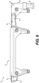
- FIGs. 7 and 8 provide longitudinal cross-sections of the coolant collector bracket 18 showing the internal flow passages or conduits of coolant collector bracket.
- the coolant collector bracket 18 includes two separate internal coolant channels 40, 42.
- the EGR cooler 16 ( FIG. 1 ) is in fluid communication with the two separate internal coolant channels 40, 42.
- the first internal coolant channel 40 is in fluid communication with the coolant passages of the cylinder head 14.
- the first internal coolant channel 40 directly receives coolant from the outlets 34 of the coolant passages of the cylinder head 14 and sends the coolant to the EGR cooler 16.
- the second internal coolant channel 42 is in fluid communication with the cylinder block 12. In particular, the second internal coolant channel 42 directs coolant received from the EGR cooler 16 into the cylinder block 12.
- the disclosed features and systems may be used in any appropriate engine system having a liquid cooling system, and may facilitate coolant flow within such engine systems.
- the coolant collector bracket 18 is mounted to a generally perpendicular surface of the cylinder head 14.
- the cylinder head 14 includes a first end 22, a second end 24 opposite the first end 22, a first side 26 extending between the first end 22 and the second end 24, and a second side 28 opposite the first side 26 and extending between the first end 22 and the second end 24.
- the first side 26 and the second side 28 of the cylinder head 14 each have a length that is substantially longer than a corresponding length of the first end 22 and the second end 24.
- the coolant collector bracket 18 is positioned generally parallel to the first side 26 of the cylinder head 14 and the EGR cooler 16 ( FIG. 2 ).
- the coolant collector bracket 18 is coupled to and between the cylinder head 14 and the EGR cooler 16.
- the coolant collector bracket 18 vertically supports the EGR cooler 16.
- the coolant collector bracket 18 has a generally parallel and vertical mounting interface with cylinder head 14, and a generally parallel and horizontal mounting interface with EGR cooler 16.
- FIG. 1 when the exhaust manifold 20 is coupled to the cylinder head 14, the mounting legs 31 of the coolant collector bracket 18 are located between the exhaust manifold 20 and the cylinder head 14.
- the coolant collector bracket 18 is positioned near the first side 26 of the cylinder head 14 such that slots 57 of the mounting legs 31 are slidably inserted onto the bottom fasteners 66 of the cylinder head 14. This assembly process allows the coolant collector bracket 18 to be easily secured to the cylinder head 14, and the weight of the coolant collector bracket 18 to be supported by cylinder head fasteners 52.
- the coolant collector bracket 18 described herein provides a number of features for facilitating assembly to the engine system 10.
- the jumper tube 56 of the coolant collector bracket 18 facilitates alignment of the distal end 45 of the exit leg 39.
- the slots 65 (and corresponding slot openings 64) as described above, allow for the coolant collector bracket 18 to be slidably inserted onto the corresponding bottom fasteners 66 of the cylinder head 14.
- the gaskets 58 of the coolant collector bracket 18 facilitate assembly by securely snapping in place on the mounting legs 31.
- the vertical orientation of the EGR cooler 16 coupling to the coolant collector bracket 18 allows for the EGR cooler 16 to rest on top of the coolant collector bracket 18 during coupling.
- the vertical orientation of the fastener connectors 50 of mounts 86 allows for ease of vertical assembly since the EGR cooler 16 need only be placed on the top side 48 of the coolant collector bracket 18.
- the features described herein facilitate the vertical assembly of the coolant collector bracket 18 to the engine system 10.
Landscapes
- Engineering & Computer Science (AREA)
- Chemical & Material Sciences (AREA)
- Combustion & Propulsion (AREA)
- Mechanical Engineering (AREA)
- General Engineering & Computer Science (AREA)
- Exhaust-Gas Circulating Devices (AREA)
- Cylinder Crankcases Of Internal Combustion Engines (AREA)
Description
- This disclosure relates generally to an engine system, and more specifically, to an engine system having a coolant collector associated with an exhaust gas recirculation (EGR) cooler.
- Internal combustion engines are typically liquid-cooled. A conventional coolant system for an internal combustion engine may include a coolant pump that pumps coolant into a coolant jacket of an engine block of the engine. The coolant then flows longitudinally through a portion of the coolant jacket surrounding the cylinders of the engine. The engine cylinders are cooled by the passing coolant through passages located in or adjacent the cylinder walls. The coolant may then flow into a water jacket of one or more cylinder heads to cool the components of the cylinder heads, such as injectors and valves, and then exits the engine. The coolant system may also include a number of other components, such as for example, a radiator, a thermostat, an exhaust gas recirculation (EGR) cooler, an aftercooler, and an oil cooler.
-
U.S. Pat. No. 7,516,737 ("the '737 patent") discloses an internal combustion engine with a cooling system and an exhaust gas recirculation (EGR) system. The EGR system includes an EGR heat exchanger or cooler with a coolant inlet opening connected to a coolant outlet opening of the engine for receiving coolant therefrom. The engine further includes a coolant collecting rail mounted to the engine and having a coolant inlet opening connected to the EGR heat exchanger, and at least one other coolant inlet opening in communication directly with at least one other coolant outlet opening of the engine. The cooling system of the '737 patent may have drawbacks both in one or more of manufacturing, assembly, cooling, and serviceability. - The system disclosed below may solve one or more of the problems set forth above and/or other problems in the art. The scope of the current disclosure, however, is defined by the attached claims, and not by the ability to solve any specific problem.
- In accordance with one aspect of the present disclosure, an internal combustion engine system including a cylinder block, a cylinder head attached to the cylinder block, an EGR cooler, and a coolant collector bracket is provided. The cylinder head includes a plurality of coolant passages. The coolant collector bracket is coupled to and between the cylinder head and the EGR cooler. The coolant collector bracket includes a plurality of coolant inlets directly coupled to a plurality of outlets of the plurality of coolant passages of the cylinder head. The coolant collector bracket also includes an EGR coolant outlet directly coupled to an inlet of the EGR cooler. The coolant collector bracket also includes an EGR coolant inlet directly coupled to an outlet of the EGR cooler. A first internal coolant channel is in fluid communication with the plurality of coolant passages of the cylinder head; and a second internal coolant channel in fluid communication with the cylinder block. The first internal coolant channel is fluidly separate from the second internal coolant channel, the first and second internal coolant channels fluidly coupling different inlets and outlets.
- In accordance with another aspect of the present disclosure, an internal combustion engine system including a cylinder block, a cylinder head, an EGR cooler, and a coolant collector bracket is provided. The cylinder head is vertically attached to the cylinder block and includes a plurality of coolant passages. The EGR cooler includes a plurality of mounting posts. The coolant collector bracket is directly coupled to and between the cylinder head and the EGR cooler. The coolant collector bracket is aligned to vertically support the EGR cooler. The coolant collector bracket includes a first internal channel for directly receiving coolant from a plurality of outlets of the plurality of coolant passages of the cylinder head. The coolant collector bracket also includes a second internal channel for directly communicating the coolant to the cylinder block. The coolant collector bracket is directly connected to the EGR cooler at the plurality of mounting posts. The first internal coolant channel is fluidly separate from the second internal coolant channel, the first and second internal coolant channels fluidly coupling different inlets and outlets.
- In accordance with another aspect of the present disclosure, a method of directing coolant flow through an internal combustion engine system is provided. The internal combustion engine system includes a cylinder block, a cylinder head attached to the cylinder block, an EGR cooler, and a coolant collector bracket coupled to and between the cylinder head and the EGR cooler. The method includes directly supplying coolant through a plurality of outlets of a plurality of coolant passages of the cylinder head and into a plurality of coolant inlets of the coolant collector bracket. The method also includes moving the coolant through the plurality of coolant inlets and into a first internal coolant channel of the coolant collector bracket. The method also includes directing the coolant to flow upstream through an EGR coolant outlet of the coolant collector bracket and into an inlet of the EGR cooler. The method also includes enabling the coolant to flow downstream from an outlet of the EGR cooler and into a second internal coolant channel of the coolant collector bracket to supply the coolant to the cylinder block. The first internal coolant channel is fluidly separate from the second internal coolant channel, the first and second internal coolant channels fluidly coupling different inlets and outlets.
- The accompanying drawings, which are incorporated in and constitute a part of this specification, illustrate various exemplary embodiments and together with the description, serve to explain the principles of the disclosed embodiments.
-
FIG. 1 is a front view of an exemplary embodiment of an engine system including an exhaust gas recirculation (EGR) cooler; -
FIG. 2 is a front view of the engine system ofFIG. 1 with the exhaust manifold being removed; -
FIG. 3 is a schematic illustration of an exemplary flow path of coolant through the engine system ofFIG. 1 ; -
FIG. 4 is a front view of a coolant collector bracket of the engine system ofFIG. 1 ; -
FIG. 5 is a rear view of the coolant collector bracket ofFIG. 4 ; -
FIG. 6 is a top view of the coolant collector bracket ofFIG. 4 ; -
FIG. 7 is a section view of the coolant collector bracket ofFIG. 4 ; -
FIG. 8 is a partial section view of internal channels of the coolant collector bracket ofFIG. 4 ; -
FIG. 9 is a partial perspective view of the coolant collector bracket and a jumper tube of the engine system ofFIG. 1 ; -
FIG. 10 is a front (bracket side) view of a gasket of the coolant collector bracket ofFIG. 4 ; -
FIG. 11 is a rear (engine side) view of the gasket ofFIG. 10 ; -
FIG. 12 is a bottom view of the gasket ofFIG. 10 ; and -
FIG. 13 is a partial exploded view illustrating assembly of the engine system ofFIG. 1 . - Both the foregoing general description and the following detailed description are exemplary and explanatory only and are not restrictive of the features, as claimed. As used herein, the terms "comprises," "comprising," "having," including," or other variations thereof, are intended to cover a non-exclusive inclusion such that a process, method, article, or apparatus that comprises a list of elements does not include only those elements, but may include other elements not expressly listed or inherent to such a process, method, article, or apparatus. Moreover, in this disclosure, relative terms, such as, for example, "about," "substantially," "generally," and "approximately" are used to indicate a possible variation of ±10% in the stated value.
- Referring to
FIGs. 1-2 , an exemplary embodiment of an internalcombustion engine system 10, such as a diesel engine, is shown. Theengine system 10 may provide power to various types of applications and/or machines. For example, theengine system 10 may power marine and military engines and/or a machine such as an off-highway truck, a railway locomotive, or an earth-moving machine, such as a wheel loader, excavator, dump truck, backhoe, motor grader, material handler, or the like. The term "machine" can also refer to stationary equipment like a generator that is driven by theengine system 10 to generate electricity. - As shown in
FIG. 1 , theengine system 10 includes acylinder block 12, acylinder head 14 attached to the top ofcylinder block 12, anEGR cooler 16, acoolant collector bracket 18, and an exhaust manifold 20, as is known in the art. Thecylinder block 12,cylinder head 14,EGR cooler 16, and exhaust manifold may be of any appropriate design, e.g. inline or V engine, any number of cylinders, and any fuel type - diesel, gasoline, and/or gaseous fuel. For ease of explanation, an inline, six cylinder diesel engine will be referenced hereinafter.FIG. 2 shows theengine system 10 with the exhaust manifold 20 removed, to better view thecoolant collector bracket 18. With the exhaust manifold 20 removed, individualcylinder exhaust passages 15 can be seen. Thecylinder block 12 andcylinder head 14 may further include a plurality of internal coolant passages or sumps (not shown) as part of a coolant circuit to cool theengine system 10. The coolant circuit can take any appropriate form, and may include, for example, a coolant sump, one or more coolant pumps, and a radiator or similar device (not shown). - The
EGR cooler 16 forms a portion of the EGR flow path and includes a generally cylindrical-shaped heat exchanger having anEGR inlet end 17 and outlet end 19.EGR cooler 16 may be of any appropriate type, such as a parallel tube or parallel flow heat exchanger having a coolant inlet at one end, and a coolant exit at an opposite end. In some embodiments,EGR cooler 16 may have a rectangular, oval, and/or asymmetrical shape. As will be explained in more detail below,EGR cooler 16 may include a plurality of mountingposts 30 for connecting theEGR cooler 16 to a top portion of thecoolant collector bracket 18. TheEGR cooler 16 may include four mountingposts 30, only two of which can be seen inFIGs. 1 and2 . -
FIG. 3 schematically depicts an end view ofengine system 10. As shown,coolant collector bracket 18 may be secured to a side of thecylinder head 14, and theEGR cooler 16 is secured to a top of thecoolant collector bracket 18.FIG. 3 also depicts the coolant path throughcoolant collector bracket 18 andEGR cooler 16. For example, arrow 110 shows the flow of coolant fromcylinder head 14 tocylinder block 12 to illustrate a top-down flow of coolant fromcylinder head 14 tocylinder block 12;arrows 102 depict coolant flow from thecylinder head 14 to thecoolant collector bracket 18;arrow 104 shows the coolant flow from thecoolant collector bracket 18 to the EGR cooler;arrow 106 shows the coolant flow from theEGR cooler 16 back into thecoolant collector bracket 18; andarrow 108 shows the coolant flowing fromcoolant collector bracket 18 back tocylinder block 12. In the exemplary embodiment, the coolant incoolant collector bracket 18 flows to a casted-in collector rail (not shown) incylinder block 12. This collector rail is a cylinder block configured to receive coolant fromcoolant collector bracket 18. -
FIGs. 4-8 depict thecoolant collector bracket 18 alone, removed from theengine system 10. Referring toFIG 4 ,coolant collector bracket 18 includes a longitudinally extendingbody portion 80, a plurality of mounting members or mountinglegs 31, and an exit leg (e.g., an arm) 39.Body portion 80 is mounted tocylinder head 14 to be orientated generally horizontal and includes a longitudinal length approximately the same as the longitudinal length ofEGR cooler 16.Body portion 80 may include atop portion 82 on which theEGR cooler 16 may be directly secured, and abottom portion 84 from which mountinglegs 31 extend. Referring toFIG. 6 , thetop portion 82 ofcoolant collector bracket 18 is generally planar and may include a pair of EGR cooler mounts 86, anEGR coolant outlet 36, and anEGR coolant inlet 38. Eachmount 86 may be similarly configured and onemount 87 may be located at afront end portion 91 of thecoolant collector bracket 18, and theother mount 89 may be located at arear end portion 93 of thecoolant collector bracket 18, but not as rear as theexit leg 39. Themounts 86 may each extend from the front and rear sides of thebody portion 80 generally normal to the longitudinal length of thebody portion 80.Mounts 86 may each protrude from sides of thebody portion 80 to form a widest extent of thecoolant collector bracket 18.Mounts 86 may further include a pair of fastener connectors 50 (e.g. threaded or non-threaded bolt receiving holes) at the longitudinal ends of themounts 86, andsuch fastener connectors 50 may be located to align and mate with the mountingposts 30 of the EGR cooler 16 (FIG. 1 ). Mountingposts 30 allow for the use of standard coolant face seal(s) and provides a more robust attachment betweenEGR cooler 16 andcoolant collector bracket 18. -
EGR coolant outlet 36 may be located along the longitudinal axis offront mount 87, and generally centrally positioned between thefastener connectors 50 offront mount 87.EGR coolant inlet 38 ofcoolant collector bracket 18 may similarly be located along the longitudinal axis ofrear mount 89, and generally centrally positioned between thefastener connectors 50 of therear mount 89. Further,EGR coolant outlet 36 andEGR coolant inlet 38 generally align with each other along the longitudinal direction of thebody portion 80.EGR coolant outlet 36 andEGR coolant inlet 38 are also located to align with a coolant inlet and coolant outlet, respectively, of EGR cooler 16 (not shown). - Appropriate fluid sealing systems may be provided at one or both of
EGR coolant outlet 36 andEGR coolant inlet 38 ofcoolant collector bracket 18 to sealingly connect to the coolant inlet and exit of theEGR cooler 16. For example,EGR coolant outlet 36 andEGR coolant inlet 38 may include O-ring and/or other appropriate seals. In one arrangement, such as that shown inFIG. 6 , the seals may be different between theEGR coolant outlet 36 andEGR coolant inlet 38, such as a radial O-ring seal atEGR coolant outlet 36, and aface seal 103 atEGR coolant inlet 38. Such different seals may facilitate possible misalignment between flow connections between theEGR cooler 16 and thecoolant collector bracket 18. Further, the coolant inlet of theEGR cooler 16 may include a short tube configured to be inserted into arecess 105 formed inEGR coolant outlet 36 of thecoolant collector bracket 18, and such a short tube may be omitted from the coolant outlet of theEGR cooler 16. - As best shown in
FIGs. 4 and5 ,coolant collector bracket 18 may include three mountinglegs 31. For example,coolant collector bracket 18 may include afront mounting leg 33, amiddle mounting leg 35, and arear mounting leg 37. Themiddle mounting leg 35 may be positioned closer to therear end portion 93 of thecoolant collector bracket 18 such that a distance or gap between the front mountingleg 33 and themiddle mounting leg 35 is greater than a distance or gap between the middle mountingleg 35 and therear mounting leg 37. Further,rear mounting leg 37 may be located forward ofexit leg 39. It is understood thatcoolant collector bracket 18 may include more or lessmounting legs 31, and the mountinglegs 31 may be located at different positions than depicted in the figures. - Mounting
legs 31 may each include a plurality of fastener connectors for connecting thecoolant collector bracket 18 to thecylinder head 14. The fastener connectors may be similarly arranged on each of the mountinglegs 31. Referring toFIG. 4 andfront mounting leg 33, the fastener connectors may include atop fastener connector 53, and abottom fastener connector 55. Thetop fastener connector 53 may be located adjacent a junction or transition betweenbody portion 80 andfront mounting leg 33.Top fastener connector 53 may include a generally round, threaded or non-threaded opening extending transversely throughfront mounting leg 33 from a front surface to a back surface of thereof. It is understood that thetop fastener connector 53 may take different shapes than round.Bottom fastener connector 55 may be located at a distal-most end of the front mountingleg 33, and may include a round opening that includes a bottom gap orslot 57 extending the opening through a bottom most surface offront mounting leg 33. With such abottom slot 57,bottom fastener connector 55 may form a generally C-shape. As will be discussed in more detail below, bottom fastener connector 55 (and corresponding bottom fastener connectors of the other mounting legs 31) facilitates mounting thecoolant collector bracket 18 tocylinder head 14. Both top andbottom fastener connectors legs FIGs. 4 and5 . As noted above, each of the mountinglegs 31 may be provided with the same mounting connector arrangement asfront mounting leg 33 discussed above. However, it is understood that different arrangements are contemplated forfront mounting leg 33 or any of the other mountinglegs 31. - Referring to
FIG. 5 andfront mounting 1eg 33, the back side of mountinglegs 31 may be generally similarly arranged and include a generally planar mountingsurface 41, and acoolant inlet 43. The mounting surfaces 41 of each of the mountinglegs 31 are generally coplanar and form the back-most extent ofcoolant collector bracket 18.Coolant inlets 43 may be located between top andbottom fastener connectors legs 31.Coolant inlets 43 are located to align withcoolant outlets 34 of the cylinder head 14 (FIG. 13 ). The distance between eachcoolant inlet 43 may be substantially different based on the position of and distance between mountinglegs 31. As shown inFIG. 5 , the distance betweencoolant inlet 43 offront mounting leg 33 andcoolant inlet 43 of each of the other mountinglegs 31 may be different. -
FIG. 5 showsmiddle mounting leg 35 andrear mounting leg 37 with agasket 58 mounted to the planar mountingsurface 41 of the mountinglegs 31. The particulars of the mountinggaskets 58 are further shown inFIGs. 10-12 . In particular,FIG. 10 illustrates a front view andFIG. 11 illustrates a rear view of agasket 58. As shown inFIG. 5 ,gaskets 58 are securely fastened to the mountinglegs 31 of thecoolant collector bracket 18. As shown inFIG. 12 , eachgasket 58 is sized and shaped to snap onto a surface of a corresponding mountingleg 31. Thegaskets 58 are configured to directly couple to thefirst side 26 of thecylinder head 14. As shown inFIGs. 10 and 11 , eachgasket 58 includes aninlet opening 60 corresponding to a respective coolant inlet 43 (FIG. 5 ). - As shown in
FIGs. 10-12 , eachgasket 58 includes a pair offlanges 68 that extend laterally to engage surface edges of a corresponding mountingleg 31. In the exemplary embodiment, thegaskets 58 are of a metal material. As shown inFIG. 13 , thecylinder head 14 includes a plurality of bottom fasteners 66 (e.g., bolts) positioned along a bottom edge of thefirst side 26. Thecylinder head 14 also includes a plurality ofbracket connection openings 70 configured to receive thecylinder head fasteners 52 associated with corresponding mountinglegs 31. - Referring back to
FIGs. 4-6 , exit leg (e.g., arm) 39 forms a generally L-shape extending from therear end portion 93 ofcoolant collector bracket 18. Theexit leg 39 includes a protrusion forming a seat (e.g., a flap) 54 that extends upwards from theexit leg 39 such that theseat 54 laterally protrudes from the top side 48. Theexit leg 39 includes adistal end 45 that is coupled to ajumper tube 56. Thedistal end 45 ofexit leg 39 extends generally orthogonally from thebody portion 80 andseat 54 is vertically aligned with thejumper tube 56. In the illustrated embodiment, thejumper tube 56 includes an O-ring seal member 49.FIG. 9 shows the connection between thecoolant collector bracket 18 and thecylinder block 12. Specifically, during assembly of theengine system 10, thejumper tube 56, which connects thecoolant collector bracket 18 to thecylinder block 12, provides flexibility to allow for angular misalignment between thecoolant collector bracket 18 and thecylinder block 12. -
Coolant collector bracket 18 includes a plurality of internal flow passages or conduits. The dashed arrows ofFIG. 4 depict the flow of coolant throughcoolant collector bracket 18. In particular, as shown inFIG. 4 ,distal end 45 ofexit leg 39 is fluidly coupled to theEGR coolant inlet 38 ofcoolant collector bracket 18. Further,FIGs. 7 and8 provide longitudinal cross-sections of thecoolant collector bracket 18 showing the internal flow passages or conduits of coolant collector bracket. As show, thecoolant collector bracket 18 includes two separateinternal coolant channels FIG. 1 ) is in fluid communication with the two separateinternal coolant channels internal coolant channel 40 is in fluid communication with the coolant passages of thecylinder head 14. In particular, the firstinternal coolant channel 40 directly receives coolant from theoutlets 34 of the coolant passages of thecylinder head 14 and sends the coolant to theEGR cooler 16. The secondinternal coolant channel 42 is in fluid communication with thecylinder block 12. In particular, the secondinternal coolant channel 42 directs coolant received from theEGR cooler 16 into thecylinder block 12. - The disclosed features and systems may be used in any appropriate engine system having a liquid cooling system, and may facilitate coolant flow within such engine systems.
- Referring back to
FIGs 1 and2 , thecoolant collector bracket 18 is mounted to a generally perpendicular surface of thecylinder head 14. In particular, as best shown inFIG. 13 , thecylinder head 14 includes afirst end 22, asecond end 24 opposite thefirst end 22, afirst side 26 extending between thefirst end 22 and thesecond end 24, and asecond side 28 opposite thefirst side 26 and extending between thefirst end 22 and thesecond end 24. Thefirst side 26 and thesecond side 28 of thecylinder head 14 each have a length that is substantially longer than a corresponding length of thefirst end 22 and thesecond end 24. In the illustrated embodiment, thecoolant collector bracket 18 is positioned generally parallel to thefirst side 26 of thecylinder head 14 and the EGR cooler 16 (FIG. 2 ). As shown inFIGs. 1 and2 , and schematically shown inFIG. 3 , thecoolant collector bracket 18 is coupled to and between thecylinder head 14 and theEGR cooler 16. Thecoolant collector bracket 18 vertically supports theEGR cooler 16. Thecoolant collector bracket 18 has a generally parallel and vertical mounting interface withcylinder head 14, and a generally parallel and horizontal mounting interface withEGR cooler 16. As shown inFIG. 1 , when the exhaust manifold 20 is coupled to thecylinder head 14, the mountinglegs 31 of thecoolant collector bracket 18 are located between the exhaust manifold 20 and thecylinder head 14. - Referring to
FIG. 13 , during assembly, thecoolant collector bracket 18 is positioned near thefirst side 26 of thecylinder head 14 such thatslots 57 of the mountinglegs 31 are slidably inserted onto thebottom fasteners 66 of thecylinder head 14. This assembly process allows thecoolant collector bracket 18 to be easily secured to thecylinder head 14, and the weight of thecoolant collector bracket 18 to be supported bycylinder head fasteners 52. - After positioning the
coolant collector bracket 18 near thecylinder head 14, force is vertically applied onto theseat 54 to securely couple thejumper tube 56 of thecoolant collector bracket 18 to thecylinder block 12. For example, a hammer may be used to apply force to theseat 54 to secure thejumper tube 56 to thecylinder block 12. Thejumper tube 56 assists in the alignment of thedistal end 45 of the exit leg. After securing thejumper tube 56 to thecylinder block 12, thecylinder head fasteners 52 associated with thetop fastener connector 53 of the mountinglegs 31 can be received by thebracket connection openings 70 of thecylinder head 14 to securely fasten thecoolant collector bracket 18 to thecylinder head 14. - Thus, the
coolant collector bracket 18 described herein provides a number of features for facilitating assembly to theengine system 10. For example, thejumper tube 56 of thecoolant collector bracket 18 facilitates alignment of thedistal end 45 of theexit leg 39. The slots 65 (and corresponding slot openings 64) as described above, allow for thecoolant collector bracket 18 to be slidably inserted onto the correspondingbottom fasteners 66 of thecylinder head 14. Further, thegaskets 58 of thecoolant collector bracket 18 facilitate assembly by securely snapping in place on the mountinglegs 31. Additionally, the vertical orientation of theEGR cooler 16 coupling to thecoolant collector bracket 18 allows for theEGR cooler 16 to rest on top of thecoolant collector bracket 18 during coupling. Specifically, as opposed to horizontally mounting thecoolant collector bracket 18 from the side (which would require holding theEGR cooler 16 during coupling), the vertical orientation of thefastener connectors 50 of mounts 86 (FIG. 6 ) allows for ease of vertical assembly since theEGR cooler 16 need only be placed on the top side 48 of thecoolant collector bracket 18. Thus, the features described herein facilitate the vertical assembly of thecoolant collector bracket 18 to theengine system 10.
Claims (17)
- An internal combustion engine system (10), comprising:a cylinder block (12);a cylinder head (14) attached to the cylinder block (12), the cylinder head (14) including a plurality of coolant passages;an exhaust gas recirculation (EGR) cooler (16); anda coolant collector bracket (18) coupled to and between the cylinder head (14) and the EGR cooler (16), the coolant collector bracket (18) including,a plurality of coolant inlets (43) directly coupled to a plurality of outlets (34) of the plurality of coolant passages of the cylinder head (14);an EGR coolant outlet (36) directly coupled to an inlet of the EGR cooler (16);an EGR coolant inlet (38) directly coupled to an outlet of the EGR cooler (16);a first internal coolant channel (40) in fluid communication with the plurality of coolant passages of the cylinder head (14); anda second internal coolant channel (42) in fluid communication with the cylinder block (12);characterised in that the first internal coolant channel (40) is fluidly separate from the second internal coolant channel (42), the first and second internal coolant channels (40, 42) fluidly coupling different inlets (43) and outlets.
- The internal combustion engine system (10) of Claim 1, wherein the coolant collector bracket (18) further includes a plurality of mounting legs (31) and an exit leg (39), and wherein an inlet of the EGR cooler (16) is inserted into a recess (105) formed by the EGR coolant outlet (36) of the coolant collector bracket (18).
- The internal combustion engine system (10) of Claim 2, wherein the outlet of the EGR cooler (16) is directly coupled to a surface of the EGR coolant inlet (38) of the coolant collector bracket (18).
- The internal combustion engine system (10) of Claim 1, wherein the plurality of coolant inlets (43) are fluidly coupled to the EGR coolant outlet (36) of the coolant collector bracket (18).
- The internal combustion engine system (10) of Claim 1, wherein the coolant collector bracket (18) further includes an exit leg (39), the exit leg (39) including a distal end (45) that is fluidly coupled to the EGR coolant inlet (38) of the coolant collector bracket (18).
- The internal combustion engine system (10) of Claim 1, wherein the coolant collector bracket (18) vertically supports the EGR cooler (16).
- The internal combustion engine system (10) of Claim 1, wherein the coolant collector bracket (18) is positioned generally parallel to the cylinder head (14) and the EGR cooler (16).
- The internal combustion engine system (10) of Claim 1, wherein the cylinder head (14) includes a pair of sides and a pair of edges, each of the pair of sides having a length that is substantially longer than a corresponding length of each of the pair of edges, and wherein the coolant collector bracket (18) is coupled to one of the pair of sides of the cylinder head (14).
- The internal combustion engine system (10) of Claim 1, wherein the coolant collector bracket (18) extends substantially a length of the EGR cooler (16).
- The internal combustion engine system (10) of Claim 1, wherein the coolant collector bracket (18) includes a plurality of mounts (86) protruding from sides of the coolant collector bracket (18), each of the plurality of mounts (86) forming a widest extent of the coolant collector bracket (18).
- The internal combustion engine system (10) of Claim 1, further comprising an exhaust manifold (20) coupled to the cylinder head (14), and wherein a portion of the coolant collector bracket (18) is located between the exhaust manifold (20) and the cylinder head (14).
- An internal combustion engine system (10), comprising:a cylinder block (12);a cylinder head (14) vertically attached to the cylinder block (12), the cylinder head (14) including a plurality of coolant passages;an exhaust gas recirculation (EGR) cooler (16) including a plurality of mounting posts (30); anda coolant collector bracket (18) directly coupled to and between the cylinder head (14) and the EGR cooler (16), the coolant collector bracket (18) aligned to vertically support the EGR cooler (16), the coolant collector bracket (18) including,a first internal channel (40) for directly receiving coolant from a plurality of outlets (34) of the plurality of coolant passages of the cylinder head (14); anda second internal channel (42) for directly communicating the coolant to the cylinder block (12), andwherein the coolant collector bracket (18) is directly connected to the EGR cooler (16) at the plurality of mounting posts (30);characterised in that the first internal coolant channel (40) is fluidly separate from the second internal coolant channel (42), the first and second internal coolant channels (40, 42) fluidly coupling different inlets (43) and outlets.
- The internal combustion engine system (10) of Claim 12, wherein the EGR cooler (16) is in fluid communication with the first internal channel (40) and the second internal channel (42) of the coolant collector bracket (18).
- The internal combustion engine system (10) of Claim 12, wherein the coolant collector bracket (18) is aligned substantially parallel to a side of the cylinder head (14) and is directly fastened to the side of the cylinder head (14).
- The internal combustion engine system (10) of Claim 12, wherein the coolant collector bracket (18) is mounted to a perpendicular surface of the cylinder head (14).
- The internal combustion engine system (10) of Claim 12, wherein the coolant collector bracket (18) includes a pair of EGR cooler mounts (86), and wherein each of the pair of EGR cooler mounts (86) includes a pair of fastener connectors (50) configured to mate with the plurality of mounting posts (30).
- A method of directing coolant flow through an internal combustion engine system (10), the internal combustion engine system (10) including a cylinder block (12), a cylinder head (14) attached to the cylinder block (12), an exhaust gas recirculation (EGR) cooler (16), and a coolant collector bracket (18) coupled to and between the cylinder head (14) and the EGR cooler (16), the method comprising:directly supplying coolant through a plurality of outlets (34) of a plurality of coolant passages of the cylinder head (14) and into a plurality of coolant inlets (43) of the coolant collector bracket (18);moving the coolant through the plurality of coolant inlets (43) and into a first internal coolant channel (40) of the coolant collector bracket (18);directing the coolant to flow upstream through an EGR coolant outlet (36) of the coolant collector bracket (18) and into an inlet of the EGR cooler (16); andenabling the coolant to flow downstream from an outlet of the EGR cooler (16) and into a second internal coolant channel of the coolant collector bracket (18) to supply the coolant to the cylinder block (12);characterised in that the first internal coolant channel (40) is fluidly separate from the second internal coolant channel (42), the first and second internal coolant channels (40, 42) fluidly coupling different inlets (43) and outlets.
Applications Claiming Priority (2)
| Application Number | Priority Date | Filing Date | Title |
|---|---|---|---|
| US17/119,837 US11454157B2 (en) | 2020-12-11 | 2020-12-11 | Engine system with coolant collector |
| PCT/US2021/058564 WO2022125244A1 (en) | 2020-12-11 | 2021-11-09 | Engine system with coolant collector bracket between cylinder head and egr cooler |
Publications (2)
| Publication Number | Publication Date |
|---|---|
| EP4259922A1 EP4259922A1 (en) | 2023-10-18 |
| EP4259922B1 true EP4259922B1 (en) | 2025-01-29 |
Family
ID=78822129
Family Applications (1)
| Application Number | Title | Priority Date | Filing Date |
|---|---|---|---|
| EP21820038.4A Active EP4259922B1 (en) | 2020-12-11 | 2021-11-09 | Engine system with coolant collector bracket between cylinder head and egr cooler |
Country Status (4)
| Country | Link |
|---|---|
| US (3) | US11454157B2 (en) |
| EP (1) | EP4259922B1 (en) |
| CN (1) | CN116568920A (en) |
| WO (1) | WO2022125244A1 (en) |
Family Cites Families (30)
| Publication number | Priority date | Publication date | Assignee | Title |
|---|---|---|---|---|
| US4258687A (en) * | 1979-10-09 | 1981-03-31 | Ford Motor Company | Engine with integral mounted EGR cooler |
| KR19990030479U (en) | 1997-12-30 | 1999-07-26 | 양재신 | Bracket cooling structure of exhaust gas recirculation unit |
| AT411546B (en) * | 1998-01-15 | 2004-02-25 | Man Steyr Ag | LIQUID-COOLED INTERNAL COMBUSTION ENGINE WITH EXHAUST GAS RECIRCULATING DEVICE AND DEVICE FOR COOLING RECYCLED EXHAUST |
| JP3852255B2 (en) * | 1999-11-10 | 2006-11-29 | いすゞ自動車株式会社 | EGR and oil cooling device |
| US7089890B2 (en) * | 2004-07-12 | 2006-08-15 | International Engine Intellectual Property Company, Llc | Cooling system for an internal combustion engine with exhaust gas recirculation (EGR) |
| JP4659511B2 (en) | 2005-04-28 | 2011-03-30 | 株式会社小松製作所 | EGR cooler device |
| DE102005031300B4 (en) | 2005-07-05 | 2021-05-12 | Daimler Ag | Internal combustion engine with cooling system and exhaust gas recirculation system |
| JP2009203935A (en) | 2008-02-28 | 2009-09-10 | Honda Motor Co Ltd | Cooling system of v-type engine |
| JP2009243376A (en) * | 2008-03-31 | 2009-10-22 | Tokyo Radiator Mfg Co Ltd | Egr cooler pipe mounting structure |
| US8191668B2 (en) * | 2008-08-07 | 2012-06-05 | Caterpillar Inc. | Mounting assembly for emissions control system |
| JP2012047154A (en) | 2010-08-30 | 2012-03-08 | Toyota Motor Corp | Internal combustion engine |
| EP2463503A1 (en) * | 2010-12-13 | 2012-06-13 | Perkins Engines Company Limited | A cylinder head mount |
| WO2013054711A1 (en) * | 2011-10-12 | 2013-04-18 | 本田技研工業株式会社 | Exhaust gas recirculation device for internal combustion engine |
| US9587532B1 (en) | 2012-03-22 | 2017-03-07 | Vinh Au | Oil, coolant, and exahust gas circulation system, elements and kits |
| CN102953869A (en) | 2012-11-27 | 2013-03-06 | 第一拖拉机股份有限公司 | Low-emission straight external cooling EGR (exhaust gas recirculation) system |
| US9303595B2 (en) * | 2013-08-27 | 2016-04-05 | Deere & Company | Exhaust gas recirculation cooler mount |
| US9790899B2 (en) * | 2014-05-02 | 2017-10-17 | Cummins Inc. | EGR cooling system |
| US20150102179A1 (en) | 2014-12-22 | 2015-04-16 | Caterpillar Inc. | Bracket to mount aftercooler to engine |
| KR101816356B1 (en) * | 2015-11-13 | 2018-01-08 | 현대자동차주식회사 | Engine And Cooling Method For Vehicle |
| US10330054B2 (en) * | 2016-03-24 | 2019-06-25 | Ford Global Technologies, Llc | Systems and method for an exhaust gas recirculation cooler coupled to a cylinder head |
| KR101970930B1 (en) * | 2016-03-29 | 2019-08-13 | 얀마 가부시키가이샤 | Engine gear |
| JP6473096B2 (en) * | 2016-03-29 | 2019-02-20 | ヤンマー株式会社 | Engine equipment |
| WO2017034043A1 (en) | 2016-09-26 | 2017-03-02 | 株式会社小松製作所 | Egr device and dump truck provided with same |
| JP6619375B2 (en) * | 2017-03-24 | 2019-12-11 | ヤンマー株式会社 | Engine equipment |
| JP7095234B2 (en) | 2017-06-22 | 2022-07-05 | いすゞ自動車株式会社 | Exhaust gas recirculation device |
| US10400714B2 (en) | 2017-09-28 | 2019-09-03 | Senior Ip Gmbh | Heat exchanger with annular coolant chamber |
| JP6865154B2 (en) * | 2017-12-18 | 2021-04-28 | ヤンマーパワーテクノロジー株式会社 | engine |
| CN108317018B (en) | 2017-12-29 | 2019-11-22 | 浙江锋锐发动机有限公司 | Cylinder head cooling device and preparation method thereof and cylinder cover cooling system |
| JP7541838B2 (en) * | 2020-03-13 | 2024-08-29 | ヤンマーパワーテクノロジー株式会社 | engine |
| US11492953B1 (en) * | 2021-11-09 | 2022-11-08 | Caterpillar Inc. | Heat exchanger with coolant manifold |
-
2020
- 2020-12-11 US US17/119,837 patent/US11454157B2/en active Active
-
2021
- 2021-11-09 EP EP21820038.4A patent/EP4259922B1/en active Active
- 2021-11-09 CN CN202180083193.XA patent/CN116568920A/en active Pending
- 2021-11-09 WO PCT/US2021/058564 patent/WO2022125244A1/en not_active Ceased
-
2022
- 2022-08-19 US US17/891,492 patent/US20220389856A1/en not_active Abandoned
-
2023
- 2023-05-12 US US18/316,646 patent/US12297765B2/en active Active
Also Published As
| Publication number | Publication date |
|---|---|
| CN116568920A (en) | 2023-08-08 |
| US20230279801A1 (en) | 2023-09-07 |
| US20220389856A1 (en) | 2022-12-08 |
| EP4259922A1 (en) | 2023-10-18 |
| US11454157B2 (en) | 2022-09-27 |
| US12297765B2 (en) | 2025-05-13 |
| US20220186653A1 (en) | 2022-06-16 |
| WO2022125244A1 (en) | 2022-06-16 |
Similar Documents
| Publication | Publication Date | Title |
|---|---|---|
| EP4259912B1 (en) | Mounting structure for engine coolant collector | |
| KR101999077B1 (en) | Engine device | |
| KR102239402B1 (en) | Engine unit | |
| KR101970930B1 (en) | Engine gear | |
| KR20080056685A (en) | Internal combustion engine with exhaust gas recirculation cooler | |
| WO2018173406A1 (en) | Engine device | |
| CN110199107A (en) | engine unit | |
| EP4259921B1 (en) | ENGINE COOLANT COLLECTION BRACKET | |
| CN108884750B (en) | Engine device | |
| US12297765B2 (en) | Engine system with coolant collector | |
| US11255251B2 (en) | Methods and systems for a charge air cooler | |
| AU2022256141A1 (en) | Heat exchanger with coolant manifold | |
| US8973538B2 (en) | Inline engine having side-mounted heat exchangers | |
| JP3392513B2 (en) | V-type engine exhaust recirculation system | |
| EP4177459B1 (en) | Combination of egr, egr-cooler and coolant collector bracket | |
| EP4095366B1 (en) | Cooling system for vehicle | |
| US20260085674A1 (en) | Swappable integrated coolant module | |
| US20210404424A1 (en) | Exhaust gas recirculation heat exchanger and heat shield | |
| KR20060071215A (en) | V engine cooling system |
Legal Events
| Date | Code | Title | Description |
|---|---|---|---|
| STAA | Information on the status of an ep patent application or granted ep patent |
Free format text: STATUS: UNKNOWN |
|
| STAA | Information on the status of an ep patent application or granted ep patent |
Free format text: STATUS: THE INTERNATIONAL PUBLICATION HAS BEEN MADE |
|
| PUAI | Public reference made under article 153(3) epc to a published international application that has entered the european phase |
Free format text: ORIGINAL CODE: 0009012 |
|
| STAA | Information on the status of an ep patent application or granted ep patent |
Free format text: STATUS: REQUEST FOR EXAMINATION WAS MADE |
|
| 17P | Request for examination filed |
Effective date: 20230522 |
|
| AK | Designated contracting states |
Kind code of ref document: A1 Designated state(s): AL AT BE BG CH CY CZ DE DK EE ES FI FR GB GR HR HU IE IS IT LI LT LU LV MC MK MT NL NO PL PT RO RS SE SI SK SM TR |
|
| DAV | Request for validation of the european patent (deleted) | ||
| DAX | Request for extension of the european patent (deleted) | ||
| REG | Reference to a national code |
Ref country code: DE Ref legal event code: R079 Free format text: PREVIOUS MAIN CLASS: F02M0026300000 Ipc: F02M0026230000 Ref country code: DE Ref legal event code: R079 Ref document number: 602021025566 Country of ref document: DE Free format text: PREVIOUS MAIN CLASS: F02M0026300000 Ipc: F02M0026230000 |
|
| RIC1 | Information provided on ipc code assigned before grant |
Ipc: F01P 11/04 20060101ALI20240606BHEP Ipc: F01P 3/12 20060101ALI20240606BHEP Ipc: F01P 3/02 20060101ALI20240606BHEP Ipc: F02M 26/32 20160101ALI20240606BHEP Ipc: F02M 26/30 20160101ALI20240606BHEP Ipc: F02M 26/23 20160101AFI20240606BHEP |
|
| GRAP | Despatch of communication of intention to grant a patent |
Free format text: ORIGINAL CODE: EPIDOSNIGR1 |
|
| STAA | Information on the status of an ep patent application or granted ep patent |
Free format text: STATUS: GRANT OF PATENT IS INTENDED |
|
| INTG | Intention to grant announced |
Effective date: 20240730 |
|
| GRAS | Grant fee paid |
Free format text: ORIGINAL CODE: EPIDOSNIGR3 |
|
| P01 | Opt-out of the competence of the unified patent court (upc) registered |
Free format text: CASE NUMBER: APP_56209/2024 Effective date: 20241015 |
|
| GRAA | (expected) grant |
Free format text: ORIGINAL CODE: 0009210 |
|
| STAA | Information on the status of an ep patent application or granted ep patent |
Free format text: STATUS: THE PATENT HAS BEEN GRANTED |
|
| AK | Designated contracting states |
Kind code of ref document: B1 Designated state(s): AL AT BE BG CH CY CZ DE DK EE ES FI FR GB GR HR HU IE IS IT LI LT LU LV MC MK MT NL NO PL PT RO RS SE SI SK SM TR |
|
| REG | Reference to a national code |
Ref country code: GB Ref legal event code: FG4D |
|
| REG | Reference to a national code |
Ref country code: CH Ref legal event code: EP |
|
| REG | Reference to a national code |
Ref country code: DE Ref legal event code: R096 Ref document number: 602021025566 Country of ref document: DE |
|
| REG | Reference to a national code |
Ref country code: IE Ref legal event code: FG4D |
|
| REG | Reference to a national code |
Ref country code: NL Ref legal event code: MP Effective date: 20250129 |
|
| PG25 | Lapsed in a contracting state [announced via postgrant information from national office to epo] |
Ref country code: NL Free format text: LAPSE BECAUSE OF FAILURE TO SUBMIT A TRANSLATION OF THE DESCRIPTION OR TO PAY THE FEE WITHIN THE PRESCRIBED TIME-LIMIT Effective date: 20250129 |
|
| PG25 | Lapsed in a contracting state [announced via postgrant information from national office to epo] |
Ref country code: RS Free format text: LAPSE BECAUSE OF FAILURE TO SUBMIT A TRANSLATION OF THE DESCRIPTION OR TO PAY THE FEE WITHIN THE PRESCRIBED TIME-LIMIT Effective date: 20250429 |
|
| PG25 | Lapsed in a contracting state [announced via postgrant information from national office to epo] |
Ref country code: FI Free format text: LAPSE BECAUSE OF FAILURE TO SUBMIT A TRANSLATION OF THE DESCRIPTION OR TO PAY THE FEE WITHIN THE PRESCRIBED TIME-LIMIT Effective date: 20250129 |
|
| PG25 | Lapsed in a contracting state [announced via postgrant information from national office to epo] |
Ref country code: PL Free format text: LAPSE BECAUSE OF FAILURE TO SUBMIT A TRANSLATION OF THE DESCRIPTION OR TO PAY THE FEE WITHIN THE PRESCRIBED TIME-LIMIT Effective date: 20250129 |
|
| PG25 | Lapsed in a contracting state [announced via postgrant information from national office to epo] |
Ref country code: ES Free format text: LAPSE BECAUSE OF FAILURE TO SUBMIT A TRANSLATION OF THE DESCRIPTION OR TO PAY THE FEE WITHIN THE PRESCRIBED TIME-LIMIT Effective date: 20250129 |
|
| REG | Reference to a national code |
Ref country code: LT Ref legal event code: MG9D |
|
| PG25 | Lapsed in a contracting state [announced via postgrant information from national office to epo] |
Ref country code: NO Free format text: LAPSE BECAUSE OF FAILURE TO SUBMIT A TRANSLATION OF THE DESCRIPTION OR TO PAY THE FEE WITHIN THE PRESCRIBED TIME-LIMIT Effective date: 20250429 Ref country code: IS Free format text: LAPSE BECAUSE OF FAILURE TO SUBMIT A TRANSLATION OF THE DESCRIPTION OR TO PAY THE FEE WITHIN THE PRESCRIBED TIME-LIMIT Effective date: 20250529 |
|
| REG | Reference to a national code |
Ref country code: AT Ref legal event code: MK05 Ref document number: 1763653 Country of ref document: AT Kind code of ref document: T Effective date: 20250129 |
|
| PG25 | Lapsed in a contracting state [announced via postgrant information from national office to epo] |
Ref country code: HR Free format text: LAPSE BECAUSE OF FAILURE TO SUBMIT A TRANSLATION OF THE DESCRIPTION OR TO PAY THE FEE WITHIN THE PRESCRIBED TIME-LIMIT Effective date: 20250129 |
|
| PG25 | Lapsed in a contracting state [announced via postgrant information from national office to epo] |
Ref country code: PT Free format text: LAPSE BECAUSE OF FAILURE TO SUBMIT A TRANSLATION OF THE DESCRIPTION OR TO PAY THE FEE WITHIN THE PRESCRIBED TIME-LIMIT Effective date: 20250529 Ref country code: LV Free format text: LAPSE BECAUSE OF FAILURE TO SUBMIT A TRANSLATION OF THE DESCRIPTION OR TO PAY THE FEE WITHIN THE PRESCRIBED TIME-LIMIT Effective date: 20250129 |
|
| PG25 | Lapsed in a contracting state [announced via postgrant information from national office to epo] |
Ref country code: BG Free format text: LAPSE BECAUSE OF FAILURE TO SUBMIT A TRANSLATION OF THE DESCRIPTION OR TO PAY THE FEE WITHIN THE PRESCRIBED TIME-LIMIT Effective date: 20250129 Ref country code: GR Free format text: LAPSE BECAUSE OF FAILURE TO SUBMIT A TRANSLATION OF THE DESCRIPTION OR TO PAY THE FEE WITHIN THE PRESCRIBED TIME-LIMIT Effective date: 20250430 |
|
| PG25 | Lapsed in a contracting state [announced via postgrant information from national office to epo] |
Ref country code: AT Free format text: LAPSE BECAUSE OF FAILURE TO SUBMIT A TRANSLATION OF THE DESCRIPTION OR TO PAY THE FEE WITHIN THE PRESCRIBED TIME-LIMIT Effective date: 20250129 |
|
| PG25 | Lapsed in a contracting state [announced via postgrant information from national office to epo] |
Ref country code: SE Free format text: LAPSE BECAUSE OF FAILURE TO SUBMIT A TRANSLATION OF THE DESCRIPTION OR TO PAY THE FEE WITHIN THE PRESCRIBED TIME-LIMIT Effective date: 20250129 |
|
| PG25 | Lapsed in a contracting state [announced via postgrant information from national office to epo] |
Ref country code: SM Free format text: LAPSE BECAUSE OF FAILURE TO SUBMIT A TRANSLATION OF THE DESCRIPTION OR TO PAY THE FEE WITHIN THE PRESCRIBED TIME-LIMIT Effective date: 20250129 |
|
| PG25 | Lapsed in a contracting state [announced via postgrant information from national office to epo] |
Ref country code: DK Free format text: LAPSE BECAUSE OF FAILURE TO SUBMIT A TRANSLATION OF THE DESCRIPTION OR TO PAY THE FEE WITHIN THE PRESCRIBED TIME-LIMIT Effective date: 20250129 |
|
| PG25 | Lapsed in a contracting state [announced via postgrant information from national office to epo] |
Ref country code: IT Free format text: LAPSE BECAUSE OF FAILURE TO SUBMIT A TRANSLATION OF THE DESCRIPTION OR TO PAY THE FEE WITHIN THE PRESCRIBED TIME-LIMIT Effective date: 20250129 |
|
| PG25 | Lapsed in a contracting state [announced via postgrant information from national office to epo] |
Ref country code: EE Free format text: LAPSE BECAUSE OF FAILURE TO SUBMIT A TRANSLATION OF THE DESCRIPTION OR TO PAY THE FEE WITHIN THE PRESCRIBED TIME-LIMIT Effective date: 20250129 Ref country code: CZ Free format text: LAPSE BECAUSE OF FAILURE TO SUBMIT A TRANSLATION OF THE DESCRIPTION OR TO PAY THE FEE WITHIN THE PRESCRIBED TIME-LIMIT Effective date: 20250129 |
|
| PG25 | Lapsed in a contracting state [announced via postgrant information from national office to epo] |
Ref country code: RO Free format text: LAPSE BECAUSE OF FAILURE TO SUBMIT A TRANSLATION OF THE DESCRIPTION OR TO PAY THE FEE WITHIN THE PRESCRIBED TIME-LIMIT Effective date: 20250129 |
|
| PG25 | Lapsed in a contracting state [announced via postgrant information from national office to epo] |
Ref country code: SK Free format text: LAPSE BECAUSE OF FAILURE TO SUBMIT A TRANSLATION OF THE DESCRIPTION OR TO PAY THE FEE WITHIN THE PRESCRIBED TIME-LIMIT Effective date: 20250129 |
|
| REG | Reference to a national code |
Ref country code: DE Ref legal event code: R097 Ref document number: 602021025566 Country of ref document: DE |
|
| PLBE | No opposition filed within time limit |
Free format text: ORIGINAL CODE: 0009261 |
|
| STAA | Information on the status of an ep patent application or granted ep patent |
Free format text: STATUS: NO OPPOSITION FILED WITHIN TIME LIMIT |
|
| 26N | No opposition filed |
Effective date: 20251030 |
|
| PGFP | Annual fee paid to national office [announced via postgrant information from national office to epo] |
Ref country code: DE Payment date: 20251022 Year of fee payment: 5 |
|
| PGFP | Annual fee paid to national office [announced via postgrant information from national office to epo] |
Ref country code: GB Payment date: 20251023 Year of fee payment: 5 |