EP4259233B1 - Peritonealdialysesystem mit verteileranordnung und peristaltischer pumpe - Google Patents
Peritonealdialysesystem mit verteileranordnung und peristaltischer pumpe Download PDFInfo
- Publication number
- EP4259233B1 EP4259233B1 EP21839754.5A EP21839754A EP4259233B1 EP 4259233 B1 EP4259233 B1 EP 4259233B1 EP 21839754 A EP21839754 A EP 21839754A EP 4259233 B1 EP4259233 B1 EP 4259233B1
- Authority
- EP
- European Patent Office
- Prior art keywords
- chamber
- dialysis fluid
- peristaltic pump
- manifold
- capacitive sensing
- Prior art date
- Legal status (The legal status is an assumption and is not a legal conclusion. Google has not performed a legal analysis and makes no representation as to the accuracy of the status listed.)
- Active
Links
Images








Classifications
-
- A—HUMAN NECESSITIES
- A61—MEDICAL OR VETERINARY SCIENCE; HYGIENE
- A61M—DEVICES FOR INTRODUCING MEDIA INTO, OR ONTO, THE BODY; DEVICES FOR TRANSDUCING BODY MEDIA OR FOR TAKING MEDIA FROM THE BODY; DEVICES FOR PRODUCING OR ENDING SLEEP OR STUPOR
- A61M1/00—Suction or pumping devices for medical purposes; Devices for carrying-off, for treatment of, or for carrying-over, body-liquids; Drainage systems
- A61M1/14—Dialysis systems; Artificial kidneys; Blood oxygenators ; Reciprocating systems for treatment of body fluids, e.g. single needle systems for hemofiltration or pheresis
- A61M1/28—Peritoneal dialysis ; Other peritoneal treatment, e.g. oxygenation
- A61M1/282—Operational modes
-
- A—HUMAN NECESSITIES
- A61—MEDICAL OR VETERINARY SCIENCE; HYGIENE
- A61M—DEVICES FOR INTRODUCING MEDIA INTO, OR ONTO, THE BODY; DEVICES FOR TRANSDUCING BODY MEDIA OR FOR TAKING MEDIA FROM THE BODY; DEVICES FOR PRODUCING OR ENDING SLEEP OR STUPOR
- A61M1/00—Suction or pumping devices for medical purposes; Devices for carrying-off, for treatment of, or for carrying-over, body-liquids; Drainage systems
- A61M1/14—Dialysis systems; Artificial kidneys; Blood oxygenators ; Reciprocating systems for treatment of body fluids, e.g. single needle systems for hemofiltration or pheresis
- A61M1/15—Dialysis systems; Artificial kidneys; Blood oxygenators ; Reciprocating systems for treatment of body fluids, e.g. single needle systems for hemofiltration or pheresis with a cassette forming partially or totally the flow circuit for the treating fluid, e.g. the dialysate fluid circuit or the treating gas circuit
-
- A—HUMAN NECESSITIES
- A61—MEDICAL OR VETERINARY SCIENCE; HYGIENE
- A61M—DEVICES FOR INTRODUCING MEDIA INTO, OR ONTO, THE BODY; DEVICES FOR TRANSDUCING BODY MEDIA OR FOR TAKING MEDIA FROM THE BODY; DEVICES FOR PRODUCING OR ENDING SLEEP OR STUPOR
- A61M1/00—Suction or pumping devices for medical purposes; Devices for carrying-off, for treatment of, or for carrying-over, body-liquids; Drainage systems
- A61M1/14—Dialysis systems; Artificial kidneys; Blood oxygenators ; Reciprocating systems for treatment of body fluids, e.g. single needle systems for hemofiltration or pheresis
- A61M1/15—Dialysis systems; Artificial kidneys; Blood oxygenators ; Reciprocating systems for treatment of body fluids, e.g. single needle systems for hemofiltration or pheresis with a cassette forming partially or totally the flow circuit for the treating fluid, e.g. the dialysate fluid circuit or the treating gas circuit
- A61M1/152—Details related to the interface between cassette and machine
-
- A—HUMAN NECESSITIES
- A61—MEDICAL OR VETERINARY SCIENCE; HYGIENE
- A61M—DEVICES FOR INTRODUCING MEDIA INTO, OR ONTO, THE BODY; DEVICES FOR TRANSDUCING BODY MEDIA OR FOR TAKING MEDIA FROM THE BODY; DEVICES FOR PRODUCING OR ENDING SLEEP OR STUPOR
- A61M1/00—Suction or pumping devices for medical purposes; Devices for carrying-off, for treatment of, or for carrying-over, body-liquids; Drainage systems
- A61M1/14—Dialysis systems; Artificial kidneys; Blood oxygenators ; Reciprocating systems for treatment of body fluids, e.g. single needle systems for hemofiltration or pheresis
- A61M1/15—Dialysis systems; Artificial kidneys; Blood oxygenators ; Reciprocating systems for treatment of body fluids, e.g. single needle systems for hemofiltration or pheresis with a cassette forming partially or totally the flow circuit for the treating fluid, e.g. the dialysate fluid circuit or the treating gas circuit
- A61M1/152—Details related to the interface between cassette and machine
- A61M1/1524—Details related to the interface between cassette and machine the interface providing means for actuating on functional elements of the cassette, e.g. plungers
-
- A—HUMAN NECESSITIES
- A61—MEDICAL OR VETERINARY SCIENCE; HYGIENE
- A61M—DEVICES FOR INTRODUCING MEDIA INTO, OR ONTO, THE BODY; DEVICES FOR TRANSDUCING BODY MEDIA OR FOR TAKING MEDIA FROM THE BODY; DEVICES FOR PRODUCING OR ENDING SLEEP OR STUPOR
- A61M1/00—Suction or pumping devices for medical purposes; Devices for carrying-off, for treatment of, or for carrying-over, body-liquids; Drainage systems
- A61M1/14—Dialysis systems; Artificial kidneys; Blood oxygenators ; Reciprocating systems for treatment of body fluids, e.g. single needle systems for hemofiltration or pheresis
- A61M1/15—Dialysis systems; Artificial kidneys; Blood oxygenators ; Reciprocating systems for treatment of body fluids, e.g. single needle systems for hemofiltration or pheresis with a cassette forming partially or totally the flow circuit for the treating fluid, e.g. the dialysate fluid circuit or the treating gas circuit
- A61M1/154—Dialysis systems; Artificial kidneys; Blood oxygenators ; Reciprocating systems for treatment of body fluids, e.g. single needle systems for hemofiltration or pheresis with a cassette forming partially or totally the flow circuit for the treating fluid, e.g. the dialysate fluid circuit or the treating gas circuit with sensing means or components thereof
-
- A—HUMAN NECESSITIES
- A61—MEDICAL OR VETERINARY SCIENCE; HYGIENE
- A61M—DEVICES FOR INTRODUCING MEDIA INTO, OR ONTO, THE BODY; DEVICES FOR TRANSDUCING BODY MEDIA OR FOR TAKING MEDIA FROM THE BODY; DEVICES FOR PRODUCING OR ENDING SLEEP OR STUPOR
- A61M1/00—Suction or pumping devices for medical purposes; Devices for carrying-off, for treatment of, or for carrying-over, body-liquids; Drainage systems
- A61M1/14—Dialysis systems; Artificial kidneys; Blood oxygenators ; Reciprocating systems for treatment of body fluids, e.g. single needle systems for hemofiltration or pheresis
- A61M1/15—Dialysis systems; Artificial kidneys; Blood oxygenators ; Reciprocating systems for treatment of body fluids, e.g. single needle systems for hemofiltration or pheresis with a cassette forming partially or totally the flow circuit for the treating fluid, e.g. the dialysate fluid circuit or the treating gas circuit
- A61M1/155—Dialysis systems; Artificial kidneys; Blood oxygenators ; Reciprocating systems for treatment of body fluids, e.g. single needle systems for hemofiltration or pheresis with a cassette forming partially or totally the flow circuit for the treating fluid, e.g. the dialysate fluid circuit or the treating gas circuit with treatment-fluid pumping means or components thereof
-
- A—HUMAN NECESSITIES
- A61—MEDICAL OR VETERINARY SCIENCE; HYGIENE
- A61M—DEVICES FOR INTRODUCING MEDIA INTO, OR ONTO, THE BODY; DEVICES FOR TRANSDUCING BODY MEDIA OR FOR TAKING MEDIA FROM THE BODY; DEVICES FOR PRODUCING OR ENDING SLEEP OR STUPOR
- A61M1/00—Suction or pumping devices for medical purposes; Devices for carrying-off, for treatment of, or for carrying-over, body-liquids; Drainage systems
- A61M1/14—Dialysis systems; Artificial kidneys; Blood oxygenators ; Reciprocating systems for treatment of body fluids, e.g. single needle systems for hemofiltration or pheresis
- A61M1/15—Dialysis systems; Artificial kidneys; Blood oxygenators ; Reciprocating systems for treatment of body fluids, e.g. single needle systems for hemofiltration or pheresis with a cassette forming partially or totally the flow circuit for the treating fluid, e.g. the dialysate fluid circuit or the treating gas circuit
- A61M1/156—Constructional details of the cassette, e.g. specific details on material or shape
- A61M1/1561—Constructional details of the cassette, e.g. specific details on material or shape at least one cassette surface or portion thereof being flexible, e.g. the cassette having a rigid base portion with preformed channels and being covered with a foil
-
- A—HUMAN NECESSITIES
- A61—MEDICAL OR VETERINARY SCIENCE; HYGIENE
- A61M—DEVICES FOR INTRODUCING MEDIA INTO, OR ONTO, THE BODY; DEVICES FOR TRANSDUCING BODY MEDIA OR FOR TAKING MEDIA FROM THE BODY; DEVICES FOR PRODUCING OR ENDING SLEEP OR STUPOR
- A61M1/00—Suction or pumping devices for medical purposes; Devices for carrying-off, for treatment of, or for carrying-over, body-liquids; Drainage systems
- A61M1/14—Dialysis systems; Artificial kidneys; Blood oxygenators ; Reciprocating systems for treatment of body fluids, e.g. single needle systems for hemofiltration or pheresis
- A61M1/15—Dialysis systems; Artificial kidneys; Blood oxygenators ; Reciprocating systems for treatment of body fluids, e.g. single needle systems for hemofiltration or pheresis with a cassette forming partially or totally the flow circuit for the treating fluid, e.g. the dialysate fluid circuit or the treating gas circuit
- A61M1/156—Constructional details of the cassette, e.g. specific details on material or shape
- A61M1/1562—Details of incorporated reservoirs
-
- A—HUMAN NECESSITIES
- A61—MEDICAL OR VETERINARY SCIENCE; HYGIENE
- A61M—DEVICES FOR INTRODUCING MEDIA INTO, OR ONTO, THE BODY; DEVICES FOR TRANSDUCING BODY MEDIA OR FOR TAKING MEDIA FROM THE BODY; DEVICES FOR PRODUCING OR ENDING SLEEP OR STUPOR
- A61M1/00—Suction or pumping devices for medical purposes; Devices for carrying-off, for treatment of, or for carrying-over, body-liquids; Drainage systems
- A61M1/14—Dialysis systems; Artificial kidneys; Blood oxygenators ; Reciprocating systems for treatment of body fluids, e.g. single needle systems for hemofiltration or pheresis
- A61M1/15—Dialysis systems; Artificial kidneys; Blood oxygenators ; Reciprocating systems for treatment of body fluids, e.g. single needle systems for hemofiltration or pheresis with a cassette forming partially or totally the flow circuit for the treating fluid, e.g. the dialysate fluid circuit or the treating gas circuit
- A61M1/156—Constructional details of the cassette, e.g. specific details on material or shape
- A61M1/1563—Details of incorporated filters
-
- A—HUMAN NECESSITIES
- A61—MEDICAL OR VETERINARY SCIENCE; HYGIENE
- A61M—DEVICES FOR INTRODUCING MEDIA INTO, OR ONTO, THE BODY; DEVICES FOR TRANSDUCING BODY MEDIA OR FOR TAKING MEDIA FROM THE BODY; DEVICES FOR PRODUCING OR ENDING SLEEP OR STUPOR
- A61M1/00—Suction or pumping devices for medical purposes; Devices for carrying-off, for treatment of, or for carrying-over, body-liquids; Drainage systems
- A61M1/14—Dialysis systems; Artificial kidneys; Blood oxygenators ; Reciprocating systems for treatment of body fluids, e.g. single needle systems for hemofiltration or pheresis
- A61M1/15—Dialysis systems; Artificial kidneys; Blood oxygenators ; Reciprocating systems for treatment of body fluids, e.g. single needle systems for hemofiltration or pheresis with a cassette forming partially or totally the flow circuit for the treating fluid, e.g. the dialysate fluid circuit or the treating gas circuit
- A61M1/156—Constructional details of the cassette, e.g. specific details on material or shape
- A61M1/1565—Details of valves
-
- A—HUMAN NECESSITIES
- A61—MEDICAL OR VETERINARY SCIENCE; HYGIENE
- A61M—DEVICES FOR INTRODUCING MEDIA INTO, OR ONTO, THE BODY; DEVICES FOR TRANSDUCING BODY MEDIA OR FOR TAKING MEDIA FROM THE BODY; DEVICES FOR PRODUCING OR ENDING SLEEP OR STUPOR
- A61M1/00—Suction or pumping devices for medical purposes; Devices for carrying-off, for treatment of, or for carrying-over, body-liquids; Drainage systems
- A61M1/14—Dialysis systems; Artificial kidneys; Blood oxygenators ; Reciprocating systems for treatment of body fluids, e.g. single needle systems for hemofiltration or pheresis
- A61M1/15—Dialysis systems; Artificial kidneys; Blood oxygenators ; Reciprocating systems for treatment of body fluids, e.g. single needle systems for hemofiltration or pheresis with a cassette forming partially or totally the flow circuit for the treating fluid, e.g. the dialysate fluid circuit or the treating gas circuit
- A61M1/159—Dialysis systems; Artificial kidneys; Blood oxygenators ; Reciprocating systems for treatment of body fluids, e.g. single needle systems for hemofiltration or pheresis with a cassette forming partially or totally the flow circuit for the treating fluid, e.g. the dialysate fluid circuit or the treating gas circuit specially adapted for peritoneal dialysis
-
- A—HUMAN NECESSITIES
- A61—MEDICAL OR VETERINARY SCIENCE; HYGIENE
- A61M—DEVICES FOR INTRODUCING MEDIA INTO, OR ONTO, THE BODY; DEVICES FOR TRANSDUCING BODY MEDIA OR FOR TAKING MEDIA FROM THE BODY; DEVICES FOR PRODUCING OR ENDING SLEEP OR STUPOR
- A61M1/00—Suction or pumping devices for medical purposes; Devices for carrying-off, for treatment of, or for carrying-over, body-liquids; Drainage systems
- A61M1/14—Dialysis systems; Artificial kidneys; Blood oxygenators ; Reciprocating systems for treatment of body fluids, e.g. single needle systems for hemofiltration or pheresis
- A61M1/28—Peritoneal dialysis ; Other peritoneal treatment, e.g. oxygenation
-
- A—HUMAN NECESSITIES
- A61—MEDICAL OR VETERINARY SCIENCE; HYGIENE
- A61M—DEVICES FOR INTRODUCING MEDIA INTO, OR ONTO, THE BODY; DEVICES FOR TRANSDUCING BODY MEDIA OR FOR TAKING MEDIA FROM THE BODY; DEVICES FOR PRODUCING OR ENDING SLEEP OR STUPOR
- A61M2205/00—General characteristics of the apparatus
- A61M2205/12—General characteristics of the apparatus with interchangeable cassettes forming partially or totally the fluid circuit
-
- A—HUMAN NECESSITIES
- A61—MEDICAL OR VETERINARY SCIENCE; HYGIENE
- A61M—DEVICES FOR INTRODUCING MEDIA INTO, OR ONTO, THE BODY; DEVICES FOR TRANSDUCING BODY MEDIA OR FOR TAKING MEDIA FROM THE BODY; DEVICES FOR PRODUCING OR ENDING SLEEP OR STUPOR
- A61M2205/00—General characteristics of the apparatus
- A61M2205/12—General characteristics of the apparatus with interchangeable cassettes forming partially or totally the fluid circuit
- A61M2205/121—General characteristics of the apparatus with interchangeable cassettes forming partially or totally the fluid circuit interface between cassette and base
-
- A—HUMAN NECESSITIES
- A61—MEDICAL OR VETERINARY SCIENCE; HYGIENE
- A61M—DEVICES FOR INTRODUCING MEDIA INTO, OR ONTO, THE BODY; DEVICES FOR TRANSDUCING BODY MEDIA OR FOR TAKING MEDIA FROM THE BODY; DEVICES FOR PRODUCING OR ENDING SLEEP OR STUPOR
- A61M2205/00—General characteristics of the apparatus
- A61M2205/12—General characteristics of the apparatus with interchangeable cassettes forming partially or totally the fluid circuit
- A61M2205/123—General characteristics of the apparatus with interchangeable cassettes forming partially or totally the fluid circuit with incorporated reservoirs
-
- A—HUMAN NECESSITIES
- A61—MEDICAL OR VETERINARY SCIENCE; HYGIENE
- A61M—DEVICES FOR INTRODUCING MEDIA INTO, OR ONTO, THE BODY; DEVICES FOR TRANSDUCING BODY MEDIA OR FOR TAKING MEDIA FROM THE BODY; DEVICES FOR PRODUCING OR ENDING SLEEP OR STUPOR
- A61M2205/00—General characteristics of the apparatus
- A61M2205/33—Controlling, regulating or measuring
-
- A—HUMAN NECESSITIES
- A61—MEDICAL OR VETERINARY SCIENCE; HYGIENE
- A61M—DEVICES FOR INTRODUCING MEDIA INTO, OR ONTO, THE BODY; DEVICES FOR TRANSDUCING BODY MEDIA OR FOR TAKING MEDIA FROM THE BODY; DEVICES FOR PRODUCING OR ENDING SLEEP OR STUPOR
- A61M2205/00—General characteristics of the apparatus
- A61M2205/33—Controlling, regulating or measuring
- A61M2205/3317—Electromagnetic, inductive or dielectric measuring means
-
- A—HUMAN NECESSITIES
- A61—MEDICAL OR VETERINARY SCIENCE; HYGIENE
- A61M—DEVICES FOR INTRODUCING MEDIA INTO, OR ONTO, THE BODY; DEVICES FOR TRANSDUCING BODY MEDIA OR FOR TAKING MEDIA FROM THE BODY; DEVICES FOR PRODUCING OR ENDING SLEEP OR STUPOR
- A61M2205/00—General characteristics of the apparatus
- A61M2205/33—Controlling, regulating or measuring
- A61M2205/3379—Masses, volumes, levels of fluids in reservoirs, flow rates
-
- A—HUMAN NECESSITIES
- A61—MEDICAL OR VETERINARY SCIENCE; HYGIENE
- A61M—DEVICES FOR INTRODUCING MEDIA INTO, OR ONTO, THE BODY; DEVICES FOR TRANSDUCING BODY MEDIA OR FOR TAKING MEDIA FROM THE BODY; DEVICES FOR PRODUCING OR ENDING SLEEP OR STUPOR
- A61M2205/00—General characteristics of the apparatus
- A61M2205/50—General characteristics of the apparatus with microprocessors or computers
-
- A—HUMAN NECESSITIES
- A61—MEDICAL OR VETERINARY SCIENCE; HYGIENE
- A61M—DEVICES FOR INTRODUCING MEDIA INTO, OR ONTO, THE BODY; DEVICES FOR TRANSDUCING BODY MEDIA OR FOR TAKING MEDIA FROM THE BODY; DEVICES FOR PRODUCING OR ENDING SLEEP OR STUPOR
- A61M2205/00—General characteristics of the apparatus
- A61M2205/70—General characteristics of the apparatus with testing or calibration facilities
-
- A—HUMAN NECESSITIES
- A61—MEDICAL OR VETERINARY SCIENCE; HYGIENE
- A61M—DEVICES FOR INTRODUCING MEDIA INTO, OR ONTO, THE BODY; DEVICES FOR TRANSDUCING BODY MEDIA OR FOR TAKING MEDIA FROM THE BODY; DEVICES FOR PRODUCING OR ENDING SLEEP OR STUPOR
- A61M2205/00—General characteristics of the apparatus
- A61M2205/75—General characteristics of the apparatus with filters
-
- A—HUMAN NECESSITIES
- A61—MEDICAL OR VETERINARY SCIENCE; HYGIENE
- A61M—DEVICES FOR INTRODUCING MEDIA INTO, OR ONTO, THE BODY; DEVICES FOR TRANSDUCING BODY MEDIA OR FOR TAKING MEDIA FROM THE BODY; DEVICES FOR PRODUCING OR ENDING SLEEP OR STUPOR
- A61M2205/00—General characteristics of the apparatus
- A61M2205/75—General characteristics of the apparatus with filters
- A61M2205/7536—General characteristics of the apparatus with filters allowing gas passage, but preventing liquid passage, e.g. liquophobic, hydrophobic, water-repellent membranes
Definitions
- the present disclosure relates generally to medical fluid treatments and in particular to dialysis fluid treatments.
- Dialysis removes waste, toxins and excess water from the body that normal functioning kidneys would otherwise remove. Dialysis treatment for replacement of kidney functions is critical to many people because the treatment is lifesaving.
- kidney failure therapy is Hemodialysis ("HD"), which in general uses diffusion to remove waste products from a patient's blood. A diffusive gradient occurs across the semi-permeable dialyzer between the blood and an electrolyte solution called dialysate or dialysis fluid to cause diffusion.
- HD Hemodialysis
- Hemofiltration is an alternative renal replacement therapy that relies on a convective transport of toxins from the patient's blood.
- HF is accomplished by adding substitution or replacement fluid to the extracorporeal circuit during treatment.
- the substitution fluid and the fluid accumulated by the patient in between treatments is ultrafiltered over the course of the HF treatment, providing a convective transport mechanism that is particularly beneficial in removing middle and large molecules.
- HDF Hemodiafiltration
- dialysis fluid flowing through a dialyzer similar to standard hemodialysis, to provide diffusive clearance.
- substitution solution is provided directly to the extracorporeal circuit, providing convective clearance.
- HHD home hemodialysis
- HF HF
- HDF high-density hemodialysis
- a trend towards home hemodialysis (“HHD") exists today in part because HHD can be performed daily, offering therapeutic benefits over in-center hemodialysis treatments, which occur typically bi- or triweekly.
- a patient receiving more frequent treatments does not experience as much of a down cycle (swings in fluids and toxins) as does an in-center patient, who has built-up two or three days' worth of toxins prior to a treatment.
- the closest dialysis center can be many miles from the patient's home, causing door-to-door treatment time to consume a large portion of the day.
- Treatments in centers close to the patient's home may also consume a large portion of the patient's day.
- HHD can take place overnight or during the day while the patient relaxes, works
- kidney failure therapy is peritoneal dialysis ("PD"), which infuses a dialysis solution, also called dialysis fluid, into a patient's peritoneal chamber via a catheter.
- the dialysis fluid is in contact with the peritoneal membrane in the patient's peritoneal chamber. Waste, toxins and excess water pass from the patient's bloodstream, through the capillaries in the peritoneal membrane, and into the dialysis fluid due to diffusion and osmosis, i.e., an osmotic gradient occurs across the membrane.
- An osmotic agent in the PD dialysis fluid provides the osmotic gradient. Used or spent dialysis fluid is drained from the patient, removing waste, toxins and excess water from the patient. This cycle is repeated, e.g., multiple times.
- CAPD continuous ambulatory peritoneal dialysis
- APD automated peritoneal dialysis
- CFPD continuous flow peritoneal dialysis
- CAPD is a manual dialysis treatment.
- the patient manually connects an implanted catheter to a drain to allow used or spent dialysis fluid to drain from the peritoneal chamber.
- the patient then switches fluid communication so that the patient catheter communicates with a bag of fresh dialysis fluid to infuse the fresh dialysis fluid through the catheter and into the patient.
- the patient disconnects the catheter from the fresh dialysis fluid bag and allows the dialysis fluid to dwell within the peritoneal chamber, wherein the transfer of waste, toxins and excess water takes place. After a dwell period, the patient repeats the manual dialysis procedure, for example, four times per day. Manual peritoneal dialysis requires a significant amount of time and effort from the patient, leaving ample room for improvement.
- APD Automated peritoneal dialysis
- CAPD Automated peritoneal dialysis
- APD machines perform the cycles automatically, typically while the patient sleeps.
- APD machines free patients from having to manually perform the treatment cycles and from having to transport supplies during the day.
- APD machines connect fluidly to an implanted catheter, to a source or bag of fresh dialysis fluid and to a fluid drain.
- APD machines pump fresh dialysis fluid from a dialysis fluid source, through the catheter and into the patient's peritoneal chamber.
- APD machines also allow for the dialysis fluid to dwell within the chamber and for the transfer of waste, toxins and excess water to take place.
- the source may include multiple liters of dialysis fluid including several solution bags.
- APD machines pump used or spent dialysate from the patient's peritoneal cavity, though the catheter, and to the drain. As with the manual process, several drain, fill and dwell cycles occur during dialysis. A "last fill” may occur at the end of the APD treatment. The last fill fluid may remain in the peritoneal chamber of the patient until the start of the next treatment, or may be manually emptied at some point during the day.
- Known APD systems include a machine or cycler that accepts and actuates a pumping cassette having a hard part and a soft part that is deformable for performing pumping and valving operations. Sealing the fluid disposable cassette with a pneumatic path via a gasket to provide actuation has proven to be a potential field issue, which can delay treatment start time and affect user experience. Pneumatic cassette systems also produce acoustic noise, which may be a source of customer dissatisfaction.
- US 2005/209563 discloses a cassette-based medical fluid therapy system and method.
- a head height sensing and compensating method and apparatus; an admixing method and apparatus; a pH measuring method and apparatus; an air detecting and removal methods and apparatuses; an active priming apparatus and method; and a volumetric accuracy improvement apparatus and method are described.
- US 2003/136189 discloses a fluid volumetric pumping system having a fluid pump and capacitor plates disposed around a pump chamber of the fluid pump.
- the capacitance between the capacitor plates changes as the volume of fluid in the pump chamber changes.
- An electrical circuit measures a change in the capacitance between the plates and outputs a signal indicative of the volume of fluid in the pump chamber.
- the pump having the capacitance sensor fluidly connects to a patient.
- a peritoneal dialysis system provides dialysate to the patient via the pump, and the capacitance sensor measures the volume of dialysate supplied to and drained from a peritoneal cavity of the patient.
- WO 2015/168280 discloses a dialysis system and method.
- the dialysis system can provide dialysis therapy to a patient in the comfort of their own home.
- the dialysis system can be configured to prepare purified water from a tap water source in real-time that is used for creating a dialysate solution.
- the dialysis system also includes features that make it easy for a patient to self-administer therapy.
- the dialysis system includes disposable cartridge and patient tubing sets that are easily installed on the dialysis system and automatically align the tubing set, sensors, venous drip chamber, and other features with the corresponding components on the dialysis system. Methods of use are also described, including automated priming sequences, blood return sequences, and dynamic balancing methods for controlling a rate of fluid transfer during different types of dialysis, including hemodialysis, ultrafiltration, and hemodiafiltration.
- US 2013/037142 discloses a system including a machine and a cassette that moves fluid from one source to another for use in dialysis.
- the machine includes at least a first set of pressure imposing valve actuators, said valve actuators being pneumatically operated and substantially adjacently disposed, and a cassette receiving portion.
- the cassette includes a housing adapted to be removably placed in the cassette receiving portion of the machine.
- the housing includes at least one inlet port adapted to be fluidly coupled to a fluid source, and at least one outlet port.
- the housing further includes an inlet manifold and a collection chamber, and at least one fluid pathway fluidly coupled to the two. In use, the fluid pathway disposed substantially adjacent the first set of valve actuators such that sequential actuation of the valve actuators moves a fluid through the pathways to the collection chamber.
- the present disclosure sets forth a streamlined automated peritoneal dialysis ("APD") cycler and associated system providing a peristaltic pump and a manifold assembly that organizes tubing and performs many functions discussed below.
- the manifold assembly includes a rigid plastic manifold, which in an embodiment is covered on one side by a plastic sheet for its for ease and cost of manufacturing.
- a rigid plastic lid is ultrasonically welded onto the rest of the rigid plastic manifold.
- the lid may include a slight ridge around its perimeter to aid in the rigidity of the lid.
- the rigid plastic manifold is inserted inside of an APD cycler, for example, in between an actuation surface and a door of the APD cycler.
- the door for example hinges open along a bottom of the cycler housing adjacent to the actuation surface.
- the rigid plastic manifold of the manifold assembly is mounted so that the plastic sheet of the manifold is located on the surface facing the door and is constrained by the door during operation.
- the APD cycler includes a peristaltic pump head, which is able to be actuated in two directions by a motor located within the housing of the APD cycler. Pinch valves are provided along the actuation surface of the APD cycler to selectively occlude tubing that extends from the rigid plastic manifold.
- An air sensor may be located along the actuation surface, e.g., behind where the patient line of the manifold assembly is mounted for operation.
- ports for receiving tubes extend from both sides of the manifold, e.g., from the right and left sides of the manifold.
- Ports extending from one side of the manifold e.g., right side viewing APD cycler from the front
- the ports from the other side of the manifold are, for example, from top to bottom, a drain port, a first heater line/first dialysis fluid container, a bypass or branch line port, a second dialysis fluid container port, a third dialysis fluid container port and a patient line port.
- the number of ports provided by each of an upper and a lower chamber are not limited by the number shown and described herein embodiment and may be more or less than shown and described.
- the rigid plastic manifold includes a rigid plastic wall that opposes the plastic sheet.
- the plastic wall abuts up against the actuation surface for operation.
- One or more apertures, such as circular holes, are formed or provided in the rigid plastic wall.
- the circular holes are covered with pressure sensing membranes.
- a pressure sensing hole and accompanying pressure sensing membrane is provided in the rigid plastic wall of each of the upper and the lower chamber of the rigid plastic manifold.
- the upper chamber is the primary air collecting chamber, which communicates with the drain port for removing air to drain.
- the lower chamber communicates fluidly with the lower-most patient line port, which is the most important location to be free of air, wherein air in the patient line naturally tends to buoy upwards away from the patient line and into the lower chamber.
- the pressure sensing apertures and corresponding pressure sensing membranes in the rigid plastic wall are provided along an air channel extending away from the upper and/or lower chamber of the manifold.
- a drain line and first dialysis fluid container/heater line extend and connect to their respective ports, which communicate fluidly with the upper chamber.
- a Y-connection or branch line, a second dialysis fluid container line, a third dialysis fluid container line and a patient line extend and connect to their respective ports, which communicate fluidly with the lower chamber.
- a peristaltic pumping tube extends between and connects to respective ports of the upper and lower chambers.
- a peristaltic pump actuator located at the actuation surface of the APD cycler rotates in a first direction to pump fresh, heated dialysis fluid from the upper chamber, through the peristaltic pumping tube, to the lower chamber, and to the patient.
- the peristaltic pump actuator rotates in the opposite direction to pump used dialysis fluid from the lower chamber, through the peristaltic pumping tube, to the upper chamber, and to drain.
- the peristaltic pump actuator also rotates in the opposite direction to pump fresh dialysis fluid from either of the second or third dialysis fluid containers into the lower chamber, through the peristaltic pumping tube, to the upper chamber, and to the previously emptied first dialysis fluid container, which is placed in operable communication with a dialysis fluid heater.
- a dialysis fluid heater By allowing the fresh dialysis fluid from each of the dialysis fluid containers to be heated in the first dialysis fluid container, the disposable dialysis fluid set only has to be loaded once for operation. Additionally, a separate dialysis fluid heating container or bag is not needed.
- the first dialysis fluid container is loaded onto dialysis fluid heater for treatment. After the first dialysis fluid container is emptied, the peristaltic pump actuator reverses and pulls fluid from the second dialysis fluid container and pushes same into the first dialysis fluid container for heating. The same procedure is performed for the third dialysis fluid supply container when the second dialysis fluid supply container is emptied.
- the Y-connection or branch line is used to enable the remaining fluid from the first dialysis fluid supply container to be pulled by the peristaltic pump actuator into the lower chamber and then pushed into the upper chamber and out to drain before the differently formulated fluid of the second (or third) dialysis fluid container is delivered to the first dialysis fluid container for heating.
- each of the upper and lower chambers of the manifold is provided with a plurality of pegs extending inwardly from the rigid plastic wall, which prevent the flexible plastic sheet from collapsing under negative pressure. If the flexible sheet is instead replaced with a rigid plastic lid then the pegs are not needed.
- a certain portion of the rigid plastic wall for each of the upper and lower chambers is not provided with pegs and serves as a capacitive sensing area for the respective upper or lower chamber.
- Each of the capacitive sensing areas of the rigid plastic wall during operation presses up against a capacitive sensing plate or electrode located along the actuation surface of the APD cycler.
- the door of the APD cycler is provided with a matching capacitive sensing plate or electrode for each chamber, which each directly oppose the capacitive sensing plates placed along the actuation surface.
- the matching upper and lower sets of capacitive sensing plates or electrodes form upper and lower capacitive sensors.
- the capacitive sensors, one for each chamber, detect an amount of air in the respective chamber. If too much air accumulates, the APD cycler stops its current routine and pushes the air to drain in a manner discussed herein.
- the APD system of the present disclosure uses capacitive level sensing to calibrate the peristaltic pump actuator, which is performed in one embodiment when enough air builds in the upper chamber that an air purge to drain needs to be performed.
- the peristaltic pump actuator is rotated in a direction to so as to pull fluid from the lower chamber into the upper chamber of the rigid plastic manifold.
- the upper capacitive sensor detects how much fluid accumulates in the upper chamber over a known amount of peristatic pump strokes or revolutions, so that the current volume/stroke of the peristaltic pump in the current direction may be calculated and used going forward when rotating the peristaltic pump actuator in that same direction, e.g., during patient draining from the lower chamber to the upper chamber.
- the lower capacitive sensor may be used additionally (for confirmation) or alternatively to detect how much fluid leaves the lower chamber over the known amount of peristatic pump strokes or revolutions, for the calculated volume/stroke of the peristaltic pump in the current direction.
- the peristaltic pump actuator is rotated in the opposite direction to push fluid from the upper chamber into the lower chamber of the rigid plastic manifold.
- the upper capacitive sensor detects how much fluid leaves the upper chamber over the known amount of peristatic pump strokes or revolutions, so that the volume/stroke of the peristaltic pump in the opposite direction may be calculated and used going forward when rotating the peristaltic pump actuator in that same opposite direction, e.g., for patient filling.
- the lower capacitive sensor may be used in addition (for confirmation) or alternatively to detect how much fluid accumulates in the lower chamber over a known amount of peristatic pump strokes or revolutions for the calculated volume/stroke of the peristaltic pump in the opposite direction.
- the upper capacitive sensor is used primarily for calibrating the peristaltic pump stroke volume.
- the lower capacitive sensor is used mainly for air management, but may be used for confirmation of the pump stroke volume calibration if needed. This configuration assumes however that air management is able to be handled in the lower chamber, which is likely in most instances. It should be appreciated however that if unwanted air from treatment does migrate into the upper chamber, the upper capacitive sensor will detect such air and be used here for air management, e.g., output to a control unit to take corrective action.
- the APD system of the present disclosure uses a three chamber rigid plastic manifold.
- the three chamber rigid plastic manifold may begin with the two chamber manifold just described, including all of its structure, functionality and alternatives.
- a third chamber is located, e.g., molded, on top of the former upper chamber, making it a middle chamber in the three chamber manifold.
- One or more aperture may be formed between the middle and upper chamber, however, it is contemplated that fluid does not flow from the middle chamber to the upper, third chamber. Instead, the upper chamber is provided to supply air to the middle chamber during a calibration sequence.
- At least one of the parallel plate capacitance sensors are provided again for the three chamber manifold, here with the middle chamber and possibly the lower chamber.
- the added upper chamber is not intended to hold fluid and does not operate with capacitive sensing plates or electrodes accordingly in one embodiment.
- the pumping operation of the alternative three chamber manifold is the same in one embodiment as that for the two chamber manifold.
- the third, upper chamber is added to perform a calibration procedure for the peristaltic pump actuator.
- fresh dialysis fluid is pulled from one of the dialysis fluid containers to prime the middle and lower chambers completely, as determined using the capacitance sensors, so that all air is pushed to drain.
- the pinch valve for the branch line leading from the first dialysis fluid container to the lower chamber is opened, and the peristaltic pump actuator is actuated at a known revolutions per minute ("rpm") in a first direction so as to move dialysis fluid from the middle chamber to the lower chamber until the middle chamber is completely empty as determined by the associated capacitance sensor, wherein fluid in the lower chamber migrates back through the open branch line into the first dialysis fluid container, air from the upper chamber is pulled into the middle chamber, and the flexible sheet covering the third chamber bows inward into the upper chamber to compensate for the air that moves from the upper chamber to the middle chamber.
- the volume of the middle chamber (V m ) is known and the time duration ( ⁇ t) needed to fully drain the middle chamber is measured.
- Knowing those two parameters and the rpm of the pump actuator actuated in the draining direction allows the stroke volume per revolution in the chamber draining direction to be calculated, namely, to be equal to V m / ⁇ t/rpm, e.g., in milliliters ("ml”)/rpm.
- a next step wherein the pinch valve for the branch line leading from the first dialysis fluid container to the lower chamber remains open, and the peristaltic pump actuator is actuated at a known revolutions per minute ("rpm") in a second direction so as to move dialysis fluid from the lower chamber to the middle chamber until the middle chamber is completely full as determined by the associated capacitance sensor, wherein fluid from the first dialysis fluid container flows through the open branch line into the lower chamber and from the lower chamber to the middle chamber, air is pushed from the middle chamber into the upper chamber, and the flexible sheet covering the upper chamber straightens within the upper chamber due to the air being pushed into the upper chamber by the dialysis fluid entering the middle chamber.
- rpm revolutions per minute
- V m The volume of the middle chamber (V m ) is known and the time duration ( ⁇ t) needed to fully fill the middle chamber is measured. Knowing those two parameters and the rpm of the pump actuator actuated in the chamber filling direction allows the stroke volume per revolution in the filling direction to be calculated, namely, to be equal to V m / ⁇ t/rpm, e.g., in ml/rev.
- a first alternative manifold adds a dedicated air port to the top chamber. Connected to the port is a tube and connector containing a hydrophobic air filter.
- a pinch valve is added to the cycler for selectively opening and closing the air filter line, which is normally closed. The pinch valve may be opened at any time air is needed for volumetric calibration, wherein the peristaltic pump is used to draw in air into, e.g., the upper chamber of the first alternative unlimited air manifolds.
- a second alternative unlimited air manifold provides a dedicated air port on the back of the manifold.
- the air port is routed to the top chamber of the manifold via an air pathway.
- a hydrophobic air filter is attached to the air port.
- the cycler provides a seal, e.g., a spring closed and pneumatically opened seal, to normally seal the hydrophobic air filter closed.
- the cycler provides a pneumatic pump and possibly a pneumatic supply tank to supply, e.g., negative pressure to overcome the spring force and open the seal to expose the hydrophobic filter.
- the cycler accordingly includes at least one pneumatic valve to open and close a pneumatic line leading to the seal.
- the pneumatic valve is normally closed until air is needed in the manifold for a volumetric calibration.
- the peristaltic pump is used again to draw in air into the top chamber at any time and for any amount of air needed for the volumetric calibration.
- the APD cycler of the present disclosure includes a control unit having one or more processor, one or more memory and a video controller that controls a user interface, such as a touch screen user interface.
- the control unit receives signals from the capacitance sensors and is programmed to use the signals to look for air during treatment and to run any one or more of the calibration procedures discussed here.
- the control unit receives signals from other sensors, such as pressure sensors and temperature sensors, and is programmed for example to use (i) pressure sensor signals as feedback to control the motor for the peristaltic pump actuator to pump at or below safe positive and negative patient pressure limits and (ii) temperature sensor signals to control the dialysis fluid heater to heat fresh dialysis fluid within the first dialysis fluid container to body temperature, e.g., 37°C.
- the control unit is configured to use the results of the peristaltic pump calibration procedures discussed herein in determining how much fresh PD fluid is delivered to the patient and how much used PD fluid is removed from the patient. That is, knowing the latest volume per revolution, the control unit counts the number of revolutions over a patient fill or patient drain (including partial revolutions) and multiplies that number by the volume per revolution to determine the volume of fluid filled or drained. It should be appreciated that the volume per revolution could instead be weight per revolution (grams/rev) where the weight of fresh or used dialysis fluid within a particular chamber of the manifold is known.
- the control unit may then initially attempt to drain the patient. If no effluent is present initially, the control unit senses same and moves directly to a first patient fill. After the first fill and during a first patient dwell, and during all subsequent patient dwells, the control unit repeats the calibration procedure to recalibrate the peristaltic pump in both counterclockwise and clockwise directions.
- Patient fills and drains may be performed using pressure and flow profiles, wherein lower pressures and flowrates are used initially, followed by higher pressures and flowrates, e.g., for 80% to 90% of the patient fill or drain, and possibly followed by a wind down period at the end of the patient fill or drain in which lower pressures and flowrates are used again.
- the control unit also includes a transceiver and a wired or wireless connection to a network, e.g., the internet, for sending treatment data to and receiving prescription instructions from a doctor's or clinician's server interfacing with a doctor's or clinician's computer.
- the control unit may send data over the network regarding an analysis of the patient's effluent, wherein the data is used to determine the effectiveness of the patient's APD treatment.
- the doctor or clinician may review the data to determine if the patient's prescription should be modified, e.g., dwell times modified and/or change in dialysis fluid formulation.
- the data sent from the APD cycler to the network may be the same as, or akin to, data obtained from a peritoneal equilibration test ("PET").
- PET peritoneal equilibration test
- PETs determine the mass transport characteristics associated with the patient's peritoneum. PETs help doctors and clinicians to decide whether a patient's PD treatment may be improved, e.g., using different dwell times and/or different PD fluid formulation. A full PET may take around five hours to complete and may involve a CAPD exchange for example using a 2.27% glucose solution. Samples of PD fluid and patient blood are taken at set times. It is known that classical parameters of peritoneal transport such as glucose reabsorption and creatinine transport have a direct correlation with the ionic conductivity of patient effluent. Conductivity has also been used to distinguish patients with and without ultrafiltration failure.
- the capacitive sensing associated with the dual and three chamber rigid plastic manifolds of the present disclosure provides an opportunity determine the conductivity associated with both the fresh and used dialysis fluid and to use the measured and determined conductivities to develop data and send the data via a network to locations that have the need and ability to clinically analyze the data for the reasons discussed above.
- the capacitance sensors of the present manifolds provide a measure of a liquid dielectric constant from which a conductivity value can be derived.
- the peritoneal effectiveness evaluation is advantageous for at least three reasons.
- the evaluation may be performed on a regular basis, even per treatment or per patient drain if desired, without having to make the patient travel to have a test performed.
- the test is easy to perform such that it does not unduly interrupt treatment.
- the capacitance measurement is non-invasive, that is, it does not require a probe or electrode to contact the fluid being sensed as is the case with typical conductivity sensors. Sterility and cost issues with such contact are thus avoided.
- a peritoneal dialysis (“PD") system comprising a cycler including an actuation surface having a peristaltic pump actuator, and at least one pair of capacitive sensing plates; a manifold assembly including a rigid manifold having first and second chambers, the rigid manifold configured and arranged to be abutted against the actuation surface for operation, wherein the at least one pair of capacitive sensing plates is positioned to be operable with at least one of the first chamber or the second chamber, and a peristaltic pump tube extending from the first chamber to the second chamber of the rigid manifold; and a control unit configured to (i) cause the peristaltic pump actuator to actuate the peristaltic pump tube to pump an amount of dialysis fluid from the second chamber to the first chamber, (ii) receive a signal from each of the at least one pair of capacitive sensing plates, the at least one signal indicative of the amount of dialysis fluid pumped, (iii) count
- Embodiments of the peritoneal dialysis system of the present invention are described below. These embodiments may be used alone or in combination.
- the current volume per revolution is for a first direction of the peristaltic pump actuator
- the control unit is further configured to (vi) cause the peristaltic pump actuator to actuate the peristaltic pump tube in a second direction to pump another amount of dialysis fluid from the first chamber to the second chamber, (vii) receive a signal from each of the at least one pair of capacitive sensing plates, the at least one signal indicative of the other amount of dialysis fluid pumped, (viii) count a number of revolutions of the peristaltic pump actuator needed to pump the other amount of dialysis fluid from the first chamber to the second chamber, (ix) determine a current volume per revolution for a second direction of the peristaltic pump actuator, and (x) use the current volume per revolution for at least one subsequent operation of the peristaltic pump actuator in the second direction.
- the first direction is a patient drain direction and the second direction is a patient fill direction.
- the first direction is also a to-dialysis fluid heater direction.
- the rigid manifold includes a third chamber, the third chamber configured to provide air for backfilling the first chamber when the other amount of dialysis fluid is pumped from the first chamber to the second chamber.
- the rigid manifold includes a third chamber, the third chamber configured to accept air from the first chamber when the amount of dialysis fluid is pumped from the second chamber to the first chamber.
- control unit is configured to repeat (i) to (v) of the seventeenth aspect in each of a plurality of cycles of a PD treatment.
- the number of revolutions takes into account a fraction of a revolution.
- control unit is configured to at least one of (i) determine a degree to which the first and second signals match, or (ii) average the first and second signals.
- the cycler includes a door that encloses the rigid manifold after the rigid manifold is abutted against the actuation surface for operation, the actuation surface containing one of the plates of the at least one pair of capacitive sensing plates, and the door containing the other plate of the at least one pair of capacitive sensing plates.
- the at least one capacitive sensing plate contained by the actuation surface is parallel to and directly opposes the at least one capacitive sensing plate contained by the door.
- using the current volume per revolution for at least one subsequent operation of the peristaltic pump actuator includes multiplying the volume per revolution by a number of revolutions recorded by the control unit during each of the at least one subsequent operation.
- control unit includes at least one processor, at least one memory and may include at least one video controller.
- the PD system is configured to exchange at least one of treatment or patient data over a network.
- the cycler includes a door that hinges closed against the rigid manifold after the rigid manifold is abutted against the actuation surface for operation, the actuation surface containing one of the plates of the at least one pair of capacitive sensing plates, and the door containing the other plate of the at least one pair of capacitive sensing plates.
- using the current volume per revolution for at least one subsequent operation of the peristaltic pump actuator includes mathematically combining the volume per revolution by a number of revolutions recorded by the control unit during each of the at least one subsequent operation.
- the cycler includes a dialysis fluid heater.
- the cycler includes at least one valve opening or closing at least one tube or line extending from the rigid manifold.
- the at least one valve may be a pinch valve.
- a dialysis fluid container in fluid communication with the rigid manifold operates as a dialysis fluid heating container.
- an encoder is provided for use with the peristaltic pump actuator, wherein the encoder allows a full revolution of 360° of the actuator to be divided into many fractions of a rotation, e.g., into 5919 fractions.
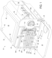
- an embodiment of system 10 includes an automated peritoneal dialysis ("APD") cycler 20 having a housing 22, which uses peristaltic pumping in the illustrated embodiment and operates with a manifold assembly 100 ( Fig. 3 ) that organizes tubing and performs many functions discussed herein.
- Manifold assembly 100 includes a rigid plastic manifold 110, which in an embodiment is covered on one side by a flexible plastic sheet 112 for its for ease and cost of manufacturing.
- plastic sheet 112 is instead a rigid lid, which is, for example, ultrasonically welded to the rest of rigid manifold 110.
- rigid lid 112 may include a slight ridge around its perimeter, which aids in the rigidity of the lid.
- Rigid plastic manifold 110, plastic sheet 112 (flexible or rigid), the fluid lines and fluid containers (discussed below) of manifold assembly 100 may be made of one or more plastic, e.g., polyvinylchloride (“PVC") or a non-PVC material, such as polyethylene (“PE”), polyurethane (“PU”) or polycarbonate (“PC”).
- Housing 22 of cycler 20 may be made of any of the above plastics, and/or of metal, e.g., stainless steel, steel and/or aluminum.
- rigid plastic manifold 110 is mounted inside of APD cycler 20, for example, in between an actuation surface 24 and a door 26 of the APD cycler.
- Door for example, hinges open via one or more hinge 28 located along a bottom of cycler housing 22, adjacent to actuation surface 24.
- rigid plastic manifold 110 of manifold assembly 100 is mounted so that plastic sheet 112 of manifold 110 is located on the surface facing door 26 (when closed), and so that manifold 110 is constrained by the door during operation.
- APD cycler 20 includes a peristaltic pump head or actuator 30, which is able to be actuated in two directions by a motor 32, e.g., a stepper or brushed or brushless DC motor, located within housing of the APD cycler.
- electrical current supplied to motor 32 may be varied for pressure control.
- the current may be limited so that pumping pressure to the patient for a patient fill is at or below a positive pressure threshold, e.g., 3 to 5 psig.
- the current may be limited so that pumping pressure from the patient for a patient drain is at or below a negative pressure threshold, e.g., -1.5 to -3 psig.
- the current may be higher for other pumping operations, e.g., positive pressure to drain and positive pressure to a dialysis fluid heating container, e.g., 7 psig.
- Pinch valves 34a to 34f are provided along the actuation surface of APD cycler 20 to selectively occlude tubing that extends from the rigid plastic manifold. Tubing is discussed in detail below, but generally, pinch valve 34a is a drain line pinch valve. Pinch valve 34b is a first dialysis fluid container/heating container valve. Pinch valve 34c is a Y-connection or branch line valve. Pinch valve 34d is a second dialysis fluid container valve. Pinch valve 34e is a third dialysis fluid container valve. Pinch valve 34f is a patient line valve. Pinch valves 34a to 34f are in one fail safe embodiment energized open and deenergized closed, electrically actuated pinch valves. In one embodiment, the inner surface of door 26 provides the surface against which pinch valves 34a to 34f occlude their respective tubing.
- actuation surface 24 defines grooves 24a to 24f for fitting and organizing the tubes of manifold assembly 100.
- Pinch valves 34a to 34f are located along grooves 24a to 24f, respectively.
- Groove 24f of actuation surface 24 is also illustrated operating with an optional air sensor 36, behind where the patient line is mounted for operation.
- air sensor 36 may however be provided in addition to the capacitance air sensing discussed herein, e.g., as a last check before fresh, heated dialysis fluid is delivered to the patient. Air sensor 36 may also be provided if the capacitance air sensing discussed herein is not employed.
- ports for receiving tubes extend from both sides of the manifold, e.g., from the right and left sides of the manifold.
- Ports from one side of manifold 110 are, for example, from top to bottom, a drain port 114a, a first heater line/first dialysis fluid container port 114b, a bypass or branch line port 114c, a second dialysis fluid container port 114d, a third dialysis fluid container port 114e and a patient line port 114f.
- Ports 114g and 114h extending from the other side of manifold 110 connect sealingly to a peristaltic pumping tube 124gh (see Fig. 3 ), which is actuated by peristaltic pump actuator 30.
- Rigid plastic manifold 110 includes a rigid plastic wall 116 that opposes plastic sheet 112. Rigid plastic wall 116 abuts up against actuation surface 24 for operation.
- One or more apertures 118a and 118b, such as circular holes, are formed or provided in rigid plastic wall 116. Circular holes 118a and 118b are covered with pressure sensing membranes.
- the pressure sensing membranes covering holes 118a and 118b abut against pressure transducers (not illustrated) provided by the cycler at actuation surface 24.
- the pressure sensors or transducers sense the pressure of fresh and used dialysis fluid entering and leaving the manifold, which is used as feedback for the electrical current control of motor 32 to regulate fluid pumping pressures as discussed above.
- a pressure sensing hole and accompanying pressure sensing membrane 118a and 118b is provided respectively in each of an upper chamber 110a and a lower chamber 110b of rigid plastic manifold 110.
- First or upper chamber 110a is the primary air collecting chamber, which communicates with drain port 114a for removing air to drain (e.g., house drain or drain container).
- Lower chamber 110b communicates fluidly with lower-most patient line port 114f, which is the most important location to be free of air, wherein air in the lower chamber 10b naturally tends to buoy upwards away from patient line port 114f.
- the number of ports 114a to 114f provided by each of upper and lower chambers 110a and 10b are not limited by the number shown and described herein embodiment and may be more or less than shown and described for either or both chambers.
- First or upper chamber 110a includes a wall or walls 120a that is/are curved to help aid dialysis fluid flow from drain or dialysis fluid/heater ports 114a and 114b to peristaltic pump port 114g or from peristaltic pump port 114g to dialysis fluid/heater ports 114a and 114b.
- Second or lower chamber 110b includes a wall 120b that extends up towards a top of lower chamber 110b, leaving a small gap G to allow dialysis fluid flow from branch line port 114c, dialysis fluid ports 114d or 114e or patient line port 114f to peristaltic pump port 114h, or from peristaltic pump port 114h to branch line port 114c, dialysis fluid ports 114d or 114e or patient line port 114f.
- Wall 120b forces the dialysis fluid to travel a longer, more tortuous path, allowing air more time and opportunity to migrate towards the top of second or lower chamber 110b.
- peristaltic pump actuator 30 is caused to rotate counterclockwise in Fig. 1 to pump dialysis fluid to in turn push air from first or lower chamber 110b into second or upper chamber 110a, where it is removed to drain via drain port 114a and associated drain line.
- Rigid plastic manifold 110 is molded, e.g., injection or blow molded to form first and second chambers 110a and 110b, apertures 118a and 118b, internal walls 120a and 120b, and pegs 122.
- each of upper chamber 110a and lower chamber 110b of manifold 110 is provided with a plurality of pegs 122 extending inwardly from the rigid plastic wall 116, which prevent flexible plastic sheet 112 from collapsing under negative pressure.
- pegs 122 are not needed or provided.
- a drain line 124a and first dialysis fluid container/heater line 124b extend and connect to their respective ports 114a and 114b, which communicate fluidly with upper chamber 110a. Drain line 124a and first dialysis fluid container/heater line 124b are routed respectively in grooves 24a and 24b of actuation surface 24 and are opened or occluded by respective valves 34a and 34b.
- a Y-connection or branch line 124c, a second dialysis fluid container line 124d, a third dialysis fluid container line 124e and a patient line 124f extend and connect to their respective ports 114c to 114f, which communicate fluidly with lower chamber 110b.
- Y-connection or branch line 124c, second dialysis fluid container line 124d, third dialysis fluid container line 124e and patient line 124f are routed respectively in grooves 24c to 24f of actuation surface 24 and are opened or occluded by respective valves 34c to 34f.
- Peristaltic pumping tube 124gh or line extends between and connects to respective ports 114g and 114h of the upper chamber 110a and lower chamber 110b.
- peristaltic pump actuator 30 located at the actuation surface of APD cycler 20 rotates in a first direction (clockwise in Figs. 1 and 3 ) to pump fresh, heated dialysis fluid from upper chamber 110a, through the peristaltic pumping tube 124gh, to lower chamber 110b, and to the patient.
- Peristaltic pump actuator 30 rotates in the opposite direction (counterclockwise in Figs.
- Fig. 3 also illustrates that manifold assembly 100 includes drain container 126a located at the distal end of drain tube or line 124a. Drain line 124a extends alternatively to a house drain, such as the patient's toilet, bathtub or sink.
- Fresh dialysis fluid containers 126b, 126d and 126e are located respectively at the distal ends of first, second and third dialysis fluid container lines 124b, 124d and 124e.
- Fresh dialysis fluid containers or bags 126b, 126d and 126e may hold different types and quantities of fresh dialysis fluid, such as different dextrose or glucose levels or formulations, e.g., container 126e may contain icodextrin, which is used for the patient's last fill.
- Containers 126b or 126d may for example hold multiple fill volume's worth of fresh dialysis fluid.
- Patient line or tube 124f extends to a patient line connector 126f, which may for example connect to a patient's transfer set leading to an indwelling catheter that extends to the patient's peritoneal cavity.
- Fig. 3 also illustrates that in addition to air sensor 36, patient line or tube 124f may also operate with a pressure sensor 38, which may be provided alternatively or in addition to membranes covering holes 118a and 118b and operating with pressure transducers located at actuation surface 24 for controlling patient pumping pressure as has been discussed herein.
- a second air sensor 36 may also operate with dialysis fluid container/heater line 124b to look for air that comes out of solution due to the heating of the fresh dialysis fluid.
- First and second air sensors 36 may be provided alternatively to or in addition to the air detection via capacitance sensing discussed herein.
- Fig. 3 schematically illustrates fresh dialysis fluid container or bag 126b operating with a dialysis fluid heater 40.
- Fig. 1 illustrates that heater 40 is located on top of housing 22 of cycler 20 in one embodiment. In an alternative embodiment, heater 40 may be located separate from housing 22, e.g., as a warming blanket or pouch. In either case, heater 40 is in one embodiment a resistive plate heater, which is configured to heat a fill volume's quantity of fresh dialysis fluid (e.g., one to two liters) from ambient temperature to body temperature (e.g., 37°C), for example, during a current patient dwell phase so that heated dialysis fluid is ready as soon as the patient is drained after the current dwell phase.
- One or more temperature sensor 42 operates with heater 40 to provide feedback for controlling the heater, e.g., using a proportional, integral, derivative control algorithm.
- peristaltic pump actuator 30 rotates in the counterclockwise direction to pump fresh dialysis fluid from either of the second or third dialysis fluid containers 126d or 126e into lower chamber 110b, through peristaltic pumping tube 124gh, to upper chamber 110a, and to the previously emptied first dialysis fluid container 126d, which is placed in operable communication with dialysis fluid heater 40.
- the fresh dialysis fluid from each of the dialysis fluid containers 126b, 126d and 126e to be heated in first dialysis fluid container or bag 126b, the disposable dialysis fluid set of manifold assembly 100 only has to be loaded once for operation. Additionally, a separate dialysis fluid heating container or bag is not needed.
- first dialysis fluid container or bag 126b is loaded onto dialysis fluid heater 40 for an initial patient fill.
- peristaltic pump actuator 30 reverses and pulls fresh dialysis fluid from second dialysis fluid container 126d and pushes same into first dialysis fluid container 126b for heating.
- the same procedure is performed for third dialysis fluid supply container 126e when second dialysis fluid supply container 126d is emptied.
- Y-connection or branch line 124c is used to enable the remaining fluid from first dialysis fluid container 126b to be pulled by the peristaltic pump actuator 30 into lower chamber 110b and then pushed into upper chamber 110a and out to drain 126a before the differently formulated fluid of the second 126d (or third 126e) dialysis fluid container is delivered to first dialysis fluid container 126b for heating.
- Y-connection or branch line 124c branches off dialysis fluid container/heater line 124b, e.g., via a Y-connector, and extends to bypass or branch line port 114c communicating with lower chamber 110b.
- Fig. 2A illustrates that sensor portions 116s of the rigid plastic wall 116 for each of upper chamber 110a and lower chamber 110b are not provided with pegs 122 and serve as a capacitive sensing areas for the respective upper chamber 110a and lower chamber 110b.
- Each of the capacitive sensing portions 116s of the rigid plastic wall 116 during operation presses up against a capacitive sensing plate or electrode located along actuation 24 surface of APD cycler 20.
- Door 26 of APD cycler 20 is provided with a matching capacitive sensing plate or electrode for each chamber 110a and 110b, which each directly oppose the capacitive sensing plates located along actuation surface 24.
- the matching upper and lower sets or pairs of capacitive sensing plates or electrodes form upper and lower capacitive sensors.
- the capacitive sensors one for each chamber 110a and 110b, detect an amount of air in the respective chamber. If too much air accumulates in chamber 110a, APD cycler 20 stops its current routine and causes peristaltic pump actuator 30 with drain line valve 34a open to rotate in a counterclockwise direction in Fig. 3 to push the air to drain 126a via drain line or tube 124a.
- Fig. 4 illustrates rigid plastic manifold 110 from the side showing its operation with a first pair of capacitive sensing plates or electrodes 44a and 44b for first or upper chamber 110a and a second or lower pair of capacitive sensing plates or electrodes 46a and 46b for second or lower chamber 110b.
- sensing plates or electrodes 44a and 46a of each sensor pair located along actuation surface 24 are active capacitor plates or electrodes and connect electrically to a signal line 48a leading to a capacitance sensing circuit 60 of a control unit 50.
- Sensing plates or electrodes 44b and 46b of each sensor pair located along door 26 are ground capacitor plates or electrodes and connect electrically to a ground line 48b leading to a ground within door 26, which communicates electrically with the ground of housing 22.
- Active plates or electrodes 44a and 46a of each sensor pair abut against capacitive sensing portions 116s of the rigid plastic wall 116 of upper and lower chambers 110a and 110b respectively.
- Ground plates or electrodes 44a and 46a of each sensor pair are parallel to and directly oppose active plates or electrodes 44a and 46a.
- Ground plates or electrodes 44a and 46a abut against flexible (or rigid) plastic sheet 112 that extends along respective upper and lower chambers 110a and 110b.
- ground plates or electrodes 44a and 46a are merged into a single ground plate or electrode.
- Table 1 air and water/dialysis fluid have very different dielectric constants. As the liquid level rises or falls between (i) plates or electrodes 44a and 44b and (ii) plates or electrodes 46a and 46b, the capacitance between the plates changes.
- Fig. 4 illustrates (i) plates or electrodes 44a and 44b abutting directly against capacitive sensing portions 116s of rigid plastic wall 116 and plastic sheet 112, respectively, and (ii) plates or electrodes 46a and 46b abutting directly against capacitive sensing portions 116s of rigid plastic wall 116 and plastic sheet 112, respectively. It is expressly contemplated to provide the direct abutting illustrated in Fig. 4 .
- Table 1 shows however that plastic, such as acrylic, has a very low dielectric compared to that of water or dialysis fluid. The plastic walls of rigid plastic manifold 110 therefore do not adversely affect the performance of the capacitive sensors.
- Control unit 50 (also illustrated in Fig. 1 ) includes one or more processor 52, one or more memory 54 and a video controller 56 that controls a user interface 58, such as a touch screen user interface. User interface 58 may alternatively or additionally be a remote user interface, e.g., via a tablet or smartphone.
- Control unit 50 also includes capacitance sensing circuits 60 that each receives signals along a signal line 48 from one of the capacitive plate pairs. Control unit 50 is programmed to use the signals to look for air during treatment and to run any one or more of the calibration procedures discussed here.
- Control unit 50 receives signals from other sensors, such as (i) pressure sensors via holes and pressure transmission membranes 118a and 118b and/or pressure sensor 38 to control patient pumping pressure and other pumping pressures discussed above via the control of current to peristaltic pump motor 32, (ii) one or more temperature sensor 42 to control dialysis fluid heater 40 to heat fresh dialysis fluid to body temperature, e.g., 37°C, and (iii) possibly additional air sensors 36.
- sensors such as (i) pressure sensors via holes and pressure transmission membranes 118a and 118b and/or pressure sensor 38 to control patient pumping pressure and other pumping pressures discussed above via the control of current to peristaltic pump motor 32, (ii) one or more temperature sensor 42 to control dialysis fluid heater 40 to heat fresh dialysis fluid to body temperature, e.g., 37°C, and (iii) possibly additional air sensors 36.
- Control unit 50 may also include a transceiver and a wired or wireless connection to a network (not illustrated), e.g., the internet, for sending treatment data to and receiving prescription instructions/changes from a doctor's or clinician's server interfacing with a doctor's or clinician's computer.
- the data sent to the doctor's or clinician's computer may be analyzed and/or converted to, or used to form, other data useful for analysis. Such data conversion is performed alternatively at control unit 50.
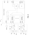
- Fig. 5 illustrates one embodiment of capacitance sensor circuit 60, which in the illustrated encompasses the capacitive sensors of both upper chamber 110a and lower chamber 110b.
- Capacitance sensor circuit 60 includes signal line 48a leading from active capacitor electrode or plate 44a, signal line 48a leading from active capacitor electrode or plate 46a, ground line 48b leading from ground electrode or plate 44b, and ground line 48b leading from ground electrode or plate 46b, as described above in connection with Fig. 4 .
- Signal lines 48a leading from the active capacitor electrode or plate each lead to an L-C subcircuit 70.
- L-C subcircuits 70 are used by an FDC2214 integrated circuit 80, forming capacitance sensor circuit 60.
- L-C subcircuits 70 each include an inductor 72 ("L") and a capacitor 74 ("C").
- the values of L and C are chosen to provide a desirable range of oscillation frequencies. As the liquid level changes between active plates 44a, 46a and ground plates 44b, 46b, the capacitance between the plates will change. The change in capacitance results in different resonant frequencies fo, which are measured by FDC2214 integrated circuit 80.
- L-C subcircuits 70 set the range of resonant frequencies fo measured. From the frequencies fo measured by FDC2214 integrated circuit 80, one or more processor 52 and one or more memory 54 of control unit 50 calculate the capacitance and the corresponding liquid level within upper chamber 110a and lower chamber 110b.
- L-C subcircuits 70 provide a number of advantages. L-C subcircuits 70 provide excellent immunity to electromagnetic interference ("EMI"). L-C subcircuits 70 also allow the operating frequency fo to be shifted if needed to avoid noise source interference.
- EMI electromagnetic interference
- the APD system 10 of the present disclosure uses capacitive sensing, including capacitance sensor circuit 60 and control unit 50, to calibrate peristaltic pump actuator 30, which is performed in one embodiment when enough air builds in the upper chamber 110a that an air purge to drain needs to be performed.
- control unit 50 causes peristaltic pump actuator 30 as viewed in Figs. 1 and 3 to rotate in a counterclockwise direction to pull fresh or used dialysis fluid from lower chamber 110b into upper chamber 110a of rigid plastic manifold 110, to purge air to drain 126a.
- Control unit 50 uses a capacitance sensor circuit 60 with upper capacitive sensing plates or electrodes 44a and 44b to determine a volume of fresh or used dialysis fluid delivered to upper chamber 110a and counts the number of pump strokes, including any partial pump stroke. Regarding partial pump strokes, it is contemplated to provide an encoder for use with peristaltic pump motor 32, wherein the encoder allows a full revolution of 360° to be divided into many fractions of a rotation, e.g., into 5919 fractions. Control unit 50 then divides the volume determined via capacitance sensor circuit 60 by the number of pump strokes to determine the volume per revolution in the counterclockwise direction.
- Control unit 50 uses that volume per revolution going forward (multiplying by counted revolutions including partial revolutions) when rotating the peristaltic pump actuator in the counterclockwise direction, e.g., for patient draining volume and flowrate determination.
- Lower capacitive sensor plates 46a and 46b may be used additionally (for confirmation) or alternatively to detect how much fluid leaves lower chamber 110b over the known amount of peristatic pump strokes or revolutions, so that the volume per revolution of the peristaltic pump in the same counterclockwise direction may be calculated and used.
- Lower capacitive sensor plates 46a and 46b and associated circuitry also form the primary sensing structure for air detection and mitigation during treatment.
- Control unit 50 then causes peristaltic pump actuator 30 to rotate in the opposite, clockwise direction as viewed in Figs. 1 to 3 to push fluid from upper chamber 110a into lower chamber 110b of rigid plastic manifold 110.
- Control unit 50 uses a capacitance sensor circuit 60 with upper capacitive sensor plates 44a and 44b to detect how much fluid leaves upper chamber 110a over a known amount of peristatic pump strokes or revolutions, including partial revolutions, so that the current volume/stroke of the peristaltic pump in the opposite, clockwise direction can be calculated and used going forward (multiplying by counted revolutions including partial revolutions) when rotating the peristaltic pump actuator in the clockwise direction, e.g., for patient filling.
- Lower capacitive sensing plates or electrodes 46a and 46b may be used additionally (for confirmation) or alternatively to detect how much fluid enters lower chamber 110b over the known amount of peristatic pump strokes or revolutions, so that the volume per revolution of the peristaltic pump in the same clockwise direction may be calculated or confirmed. Again, Lower capacitive sensing plates or electrodes 46a and 46b may be used primarily for air detection and mitigation during treatment.
- control unit 50 runs a calibration sequence 150 according to Fig. 6 to calibrate peristaltic pump actuator 30. Calibration sequence 150 may be performed at any time when at least upper chamber 110a is empty. The volume of upper chamber 110a is known. At oval 152, calibration sequence 150 begins. At block 154, control unit 50 causes drain valve drain line valve 34a and branch line valve 34c to open, while all other valves remain closed.
- control unit 50 causes peristaltic pump actuator 30 as viewed in Figs. 1 and 3 to run in a counterclockwise direction to pump fresh dialysis fluid at a known revolutions per minute ("rpm") for motor 32 (e.g., to attempt to pump at 20 ml/min).
- rpm revolutions per minute
- the counterclockwise movement of pump actuator 30 pulls fresh dialysis fluid from dialysis fluid container 126b into lower chamber 110b via branch line 124c.
- control unit 50 monitors upper capacitive sensing plates or electrodes 46a and 46b and their capacitance sensor circuit 60 once dialysis fluid enters upper chamber 110a.
- control unit 50 while monitoring the upper capacitance sensor also records the time duration needed to fill upper chamber 110a.
- control unit 50 calculates the flowrate by dividing the known volume of upper chamber 110a by the time duration just recorded.
- control unit 50 calculates the volume per revolution in the counterclockwise direction by dividing the just calculated flowrate by the known rpm.
- control unit 50 is programmed to use the just calculated volume per revolution (multiplying by counted revolutions including partial revolutions) going forward when pumping in the counterclockwise direction, e.g., for a patient drain.
- control unit 50 may calculate the volume per revolution in the clockwise direction by dividing the volume of chamber 110a by the measured time duration for draining and then dividing the resulting flowrate by the known rpm. Control unit 50 then uses the just calculated volume per revolution (multiplying by counted revolutions including partial revolutions) going forward when pumping in the clockwise direction, e.g., for a patient fill.
- method 150 ends.
- a plot showing capacitance sensor output over time is illustrated, wherein the illustrated duration of time ⁇ t is used in the calibration procedure of Fig. 6 and sequence 150.
- Time t 1 corresponds to block 160, wherein upper capacitive sensing plates or electrodes 46a and 46b and their capacitance sensor circuit 60 are monitored once dialysis fluid enters upper chamber 110a.
- Time t 2 corresponds to the end of the capacitance measuring at block 162, wherein upper chamber 110a becomes full and the capacitance no longer increases.
- the difference between t 2 and t 1 is ⁇ t, which is used in block 164 to calculate the average flowrate while filling first or upper chamber 110a.
- FIG. 8 a plot comparing capacitance sensor output against a weight scale output for a same fluid fill is illustrated.
- the output of upper capacitive sensing plates or electrodes 44a and 44b or lower capacitive sensing plates or electrodes 46a and 46b operating with their corresponding capacitance sensor circuit 60, while their respective chamber 110a or 110b is filled is plotted against the output of a weight scale weighing the same filling of the same chamber.
- Both the capacitance sensor output and the weight scale output are normalized to [0-1].
- Fig. 8 demonstrates a clear match between the two outputs, showing that the capacitance sensors of system 10 of the present disclosure are accurate.
- a plot showing an equation stored in software at one or more memory 54 for converting an output of a capacitance sensor of the present disclosure to a weight of fluid is illustrated.
- the calibration procedure may be run at a flowrate that is lower than the flowrates used typically during treatment.
- the calibration procedures may be run at 20 ml/min or other lower flowrate known to produce accurate capacitance readings.
- Filling and draining flowrates are typically in the range of 200 ml/min to 250 ml/min.
- control unit 50 of system 10 to run pressure or flow profiles for at least one of a patient fill and patient drain, which may begin at lower pressures and flowrates, ramp up to higher pressures and flowrates during the middle of the fill or drain, and ramp down to lower pressures and flowrates at the end of the fill or drain.
- Patient fill pressures may for example be controlled to be less than 1.5 psig at the beginning and/or end, e.g., for at least one of first and last 10%, of the patient fill, and then ramp up to as high as 9.5 psig during the middle 80% to 90% of the fill.
- Flowrates may correspondingly start and/or end at around 60 ml/min and then ramp up to around 200 ml/min to 250 ml/min.
- Patient drain pressures may for example be controlled to be less than -1.5 psig at the beginning and/or end, e.g., for at least one of first and last 10%, of the patient drain, and then ramp up to as high as -3.0 psig during the middle 80% to 90% of the drain.
- control unit 50 of system 10 performs an initial calibration of peristaltic pump actuator 30 and peristaltic pumping tube 124gh in both counterclockwise and clockwise directions according to any of the embodiments described herein.
- control unit 50 of system 10 assumes that the patient is full of effluent and automatically attempts an initial drain, e.g., at a low pressure and flowrate. If the patient is not full of effluent, control unit 50 of system 10 detects same immediately either by sensing a high resistance pressure caused by the empty patient catheter or by detecting air in lower chamber 110b via the capacitive sensing. Control unit 50 then proceeds to a patient fill. It is contemplated to recalibrate peristaltic pump actuator 30 and peristaltic pumping tube 124gh in both counterclockwise and clockwise directions during each patient dwell of a treatment.
- rigid plastic manifold 210 for use with system 10 is illustrated.
- Rigid plastic manifold 210 may be made of any of the materials and processes described herein and includes many of the same structure, functionality and alternatives discussed above for rigid plastic manifold 110, wherein those structures are numbered the same and not repeated here.
- rigid plastic manifold 210 includes first chamber 110a and second chamber 110b.
- manifold 210 includes a third chamber 110c that is located, e.g., molded, on top of the former upper chamber 110a, making it now the middle chamber of third chamber manifold 210.
- One or more aperture 212 is formed between first or middle chamber 110a and third or upper chamber 110c, however, it is contemplated that fluid does not flow from middle chamber 110a to the upper, third chamber 110c. Instead, upper chamber 110c is provided to supply air to middle chamber 110a during a calibration sequence discussed below.
- Fig. 10 illustrates that it is contemplated to move pressure sensing hole and accompanying pressure sensing membrane 118a from upper chamber 110a of two chamber manifold 110 to upper chamber 110c of three chamber manifold 210.
- pressure sensing hole and accompanying pressure sensing membrane 118a remains in first chamber 110a and a third pressure sensing hole and accompanying pressure sensing membrane is added to upper chamber 110c of the three chamber manifold 210.
- rigid manifold 210 provides capacitive sensing portions 116s along rigid plastic wall 116, which operate with upper capacitive sensing plates or electrodes 44a and 44b and lower capacitive sensing plates or electrodes 46a and 46b and their capacitance sensor circuit 60.
- Lower capacitive sensing plates or electrodes 46a and 46b my again be provided mainly for air detection and mitigation during treatment.
- only upper capacitive sensing plates or electrodes 44a and 44b for first chamber 110a are provided.
- the lower capacitive sensor for chamber 110b is not provided.
- added upper chamber 110c is not intended to hold fluid and does not operate with capacitive sensing plates or electrodes accordingly in one embodiment.
- Fig. 11 illustrates alternative manifold assembly 200 of system 10 using alternative rigid manifold 210.
- the tubing and containers of manifold assembly 200 may be made of any of the materials and processes described herein and includes many of the same structure, functionality and alternatives discussed above for manifold assembly 100, wherein those structures are numbered the same and not repeated here.
- valves 34a to 34f, peristaltic pump actuator 30 and heater 40 for (i) pumping fresh dialysis fluid to heater 40 for heating, (ii) pumping heated, fresh dialysis fluid to the patient, (iii) pumping used dialysis fluid to drain, (iv) removing leftover fresh dialysis fluid from dialysis fluid container 126b to drain, and (v) removing air to drain is performed for system 10 using alternative manifold assembly 200 in the same manner as described above for system 10 using manifold assembly 100.
- Figs. 12A to 12C illustrate one possible peristaltic pump calibration procedure performed under control of control unit 50 using alternative rigid manifold 210 and manifold assembly 200.
- upper chamber 110c is added to help perform the calibration procedure.
- fresh dialysis fluid is pulled from one of the dialysis fluid containers 126b, 126d or 126e to prime middle chamber 110a and lower chambers 110b completely, as determined using the upper capacitance sensor alone or in combination with the lower capacitance sensor, so that all air is pushed to drain.
- pinch valve 34c for branch line 124c leading from first dialysis fluid container 126b to lower chamber 110b is opened, and peristaltic pump actuator 30 is actuated at a known revolutions per minute ("rpm") in a first direction (clockwise in Fig.
- dialysis fluid in lower chamber 110b migrates through open branch line 124c into first dialysis fluid container 126b, (ii) air from the third, upper chamber 110c is pulled into middle chamber 110a, and (iii) flexible (or rigid) sheet 112 extended to cover third chamber 110c bows inward into the upper chamber to compensate for the air that moves from upper chamber 110c into middle chamber 110b.
- the volume of the middle chamber (V m ) is known and the time duration ( ⁇ t) needed to fully drain middle chamber 110a is measured at control unit 50.
- peristaltic pump actuator 30 is actuated at a known revolutions per minute ("rpm") in a second direction (counterclockwise in Fig.
- dialysis fluid from first dialysis fluid container 126b flows through open branch line 124c into the lower chamber 110b and from the lower chamber into middle chamber 110a, (ii) air is pushed from middle chamber 110a into upper chamber 110c, and (iii) flexible (or rigid) sheet 112 straightens within upper chamber 110c due to the air being pushed into the upper chamber by the dialysis fluid entering middle chamber 110a.
- the volume of middle chamber 110a (V m ) is known and the time ( ⁇ t) needed to fully fill the middle chamber is measured at control unit 50. Knowing those two parameters and the rpm of peristaltic pump actuator 30 actuated in the chamber filling direction (counterclockwise) allows the stroke volume per revolution in the chamber filling direction to be calculated, namely, to be equal to V m / ⁇ t/rpm, e.g., in ml/rev.
- Control unit 50 is configured to use the results of the peristaltic pump calibration procedures discussed in connection with Figs. 12A to 12C and in the other embodiments going forward to determine how much fresh PD fluid is delivered to the patient and how much used PD fluid is removed from the patient. That is, knowing the latest volume per revolution, control unit 50 thereafter counts the number of revolutions (including partial revolutions) over a patient fill or patient drain and multiples that number times the latest volume per revolution to determine the volume of fluid filled to or drained from the patient. It should be appreciated that volume per revolution could instead be weight per revolution (grams/rev), wherein the weight of fresh or used dialysis fluid within a particular chamber of the manifold is known.
- Manifold assembly 100 and alternative manifold assembly 200 in the illustrated embodiments are closed with respect to outside ambient air and rely on air generated or existing within rigid plastic manifolds 110 and 210 to perform the peristaltic pump accuracy calibration sequences discussed herein.
- Figs. 13A to 13C a first unlimited air manifold 310 for use with alternative manifold assembly 300 of alternative system 10 is illustrated.
- Rigid plastic manifold 310 may be made of any of the materials and processes described herein and includes many of the same structures, functionality and alternatives discussed above for rigid plastic manifold 110, wherein those structures are numbered the same and may not be repeated here.
- rigid plastic manifold 310 includes first chamber 110a and second chamber 110b, each covered via a flexible (or rigid) plastic sheet 112.
- Rigid plastic manifold 310 also includes drain port 114a, first heater line/first dialysis fluid container port 114b, bypass or branch line port 114c, second dialysis fluid container port 114d, third dialysis fluid container port 114e, patient line port 114f and peristaltic pump ports 114g and 114h.
- Rigid plastic manifold 310 further includes rigid plastic wall 116 having sensing portions 116s, and walls 120a and 120b provided to help guide dialysis fluid and air flow.
- Rigid plastic manifold 310 also includes pegs 122 extending inwardly from the rigid plastic wall 116, which prevent flexible plastic sheet 112 from collapsing under negative pressure. In the instance in which plastic sheet 112 is instead a rigid plastic lid, pegs 122 are not needed or provided.
- rigid plastic manifold 310 of alternative manifold assembly 300 additionally includes an air port 114ap positioned and arranged to allow filtered, ambient air to be pulled into upper chamber 110a.
- An air port line or tube 124p is made of any of the materials discussed herein and is sealed to air port 114ap via any technique described herein, e.g., ultrasonically, via heat seal or adhesively. Air port line or tube 124ap may be short, e.g., long enough to interact with a pinch valve.
- a filter connector 130 is likewise is made of any of the materials discussed herein and is sealed to the end of air port line or tube 124ap via any technique described herein.
- Filter connector 130 in the illustrated embodiment includes a filter housing 132, which houses a hydrophobic filter 134.
- Hydrophobic filter 134 is configured to allow air but not liquid, e.g., dialysis fluid, to pass through housing 132.
- Hydrophobic filter 134 also filters and purifies ambient air entering rigid plastic manifold 310 via air port line or tube 124ap, so that the air may interface with sterilized dialysis fluid.
- manifolds 110, 210, 310, 410 and 510 discussed herein may include material removal openings 128 to reduce disposable cost.
- FIGs. 13A and 13B illustrate that APD cycler 20 provides an air port valve 34ap that operates with air port line or tube 124ap.
- Air port valve 34ap is under control of control unit 50 and may be an electrically actuated solenoid pinch valve, which opens in a fail safe manner upon being energized.
- Pinch valve 34ap is typically closed during treatment to prevent air from entering manifold assembly 300 and fresh or used dialysis fluid from reaching filter connector 130 and hydrophobic filter 134.
- Control unit 50 opens pinch valve 34ap and runs peristaltic pump head or actuator 30 in a clockwise direction to pull air into upper chamber 110a at any time it is desired to calibrate the peristaltic pump actuator. In an embodiment, control unit 50 closes all other pinch valves 34a to 34f when pulling air into manifold assembly 300.
- Rigid plastic manifold 410 may be made of any of the materials and processes described herein and includes many of the same structures, functionality and alternatives discussed above for rigid plastic manifold 110, wherein those structures are numbered the same and may not be repeated here.
- rigid plastic manifold 410 includes first chamber 110a and second chamber 110b, each covered via flexible (or rigid) plastic sheet 112.
- Rigid plastic manifold 410 also includes drain port 114a, first heater line/first dialysis fluid container port 114b, bypass or branch line port 114c, second dialysis fluid container port 114d, third dialysis fluid container port 114e, patient line port 114f and peristaltic pump ports 114g and 114h.
- Rigid plastic manifold 410 further includes rigid plastic wall 116 having sensing portions 116s, and walls 120a and 120b provided to help guide fluid and air flow.
- Rigid plastic manifold 410 also includes pegs 122 extending inwardly from rigid plastic wall 116, which prevent flexible plastic sheet 112 from collapsing under negative pressure. In the instance in which plastic sheet 112 is instead a rigid plastic lid, pegs 122 are not needed or provided.
- second unlimited air manifold 410 of alternative manifold assembly 400 of system 10 additionally includes a dedicated air port 114ap located on back wall 116 of the manifold.
- Dedicated air port 114ap is routed to upper chamber 110a of manifold 410 via a molded air pathway 412.
- a hydrophobic air filter 414 is attached to the back of air port 114ap.
- Hydrophobic filter 414 is configured to allow air to be pulled into upper chamber 110a and to prevent fresh or used dialysis fluid from escaping manifold 410 into cycler 20.
- Hydrophobic filter 414 also filters and purifies ambient air entering rigid plastic manifold 410, so that the air may interface with sterilized dialysis fluid.
- Cycler 20 operating with manifold assembly 400 provides a seal (not illustrated), e.g., a spring closed and pneumatically opened seal, to normally seal the hydrophobic filter 414 closed.
- Cycler 20 provides a pneumatic pump and possibly a pneumatic supply tank to supply, e.g., negative pressure to overcome the spring force and pull the seal from hydrophobic filter 414 to expose the filter to ambient air.
- Cycler 20 accordingly includes at least one pneumatic valve under control of control unit 50 to open and close a pneumatic line leading to the seal.
- the pneumatic valve is normally closed until air is needed in rigid plastic manifold 410 for a volumetric calibration.
- Peristaltic pump actuator 30 is operated again in a clockwise direction to draw in air into top chamber 110a at any time and for any amount of air needed for the volumetric calibration.
- rigid plastic manifold 510 for use with an alternative manifold assembly 500 of alternative system 10 is illustrated.
- Rigid plastic manifold 510 may be made of any of the materials and processes described herein and includes many of the same structures, functionality and alternatives discussed above for rigid plastic manifold 110, wherein those structures are numbered the same and may not be repeated here.
- rigid plastic manifold 510 includes first chamber 110a and second chamber 110b, which in the illustrated embodiment are each covered via a rigid plastic sheet 112 (could alternatively be flexible).
- Rigid plastic manifold 510 also includes drain port 114a, first heater line/first dialysis fluid container port 114b, bypass or branch line port 114c, second dialysis fluid container port 114d, third dialysis fluid container port 114e, patient line port 114f and peristaltic pump ports 114g and 114h.
- Rigid plastic manifold 510 further includes rigid plastic wall 116 having sensing portions 116s, and walls 120a and 120b provided to help guide fluid and air flow.
- Rigid plastic manifold 510 does not require pegs 122 if employing a rigid front wall 112. Pegs 122 are provided if plastic wall 112 is flexible.
- pressure sensing aperture 118b is not provided in lower chamber 110b. Pressure sensing aperture 118b is provided instead in back wall 116 adjacent to air port 114ap. Pressure sensing aperture 118b with manifold 510 is covered by a hydrophobic filter instead of an air impermeable pressure sensing membrane. When manifold 510 is mounted to APD cycler 20 for operation, the hydrophobic filter covering hole 118b is placed in registry with a pressure transducer provided by the cycler at actuation surface 24. Pressure sensing aperture 118b and its hydrophobic filter covering are in fluid communication with lower chamber 110b via an air channel 512 located between wall 120a and an outer wall 120o of rigid plastic manifold 510.
- Air channel 512 leading upward to pressure sensing aperture 118b and its hydrophobic filter covering aids in the sensing of fresh or used dialysis fluid pressure delivered to or removed from the patient, respectively, by providing a direct communication with the pressure transducer and the air pressurized via the pressure of fresh or used dialysis fluid in lower chamber 118b via the hydrophobic filter.
- the fresh or used dialysis fluid compresses or expands the air within channel 512, which has direct communication to the pressure transducer of the cycler via the hydrophobic filter.
- control unit 50 in one embodiment includes a transceiver and a wired or wireless connection to a network, e.g., the internet, for sending treatment data to and receiving prescription instructions from a doctor's or clinician's server interfacing with a doctor's or clinician's computer.
- a network e.g., the internet
- control unit 50 to send data over the network regarding an analysis of the patient's effluent, wherein the data is used to determine the effectiveness of the patient's APD treatment.
- the doctor or clinician may review the data to determine if the patient's prescription should be modified, e.g., dwell times modified and/or a change in dialysis fluid formulation.
- the data sent from APD cycler 20 though the network to the doctor or clinician may be the same as, or akin to, data obtained from a peritoneal equilibration test ("PET").
- PET peritoneal equilibration test
- PETs determine the mass transport characteristics associated with the patient's peritoneum. PETs help doctors and clinicians to decide whether a patient's PD treatment may be improved, e.g., using different dwell times and/or different PD fluid formulation. A full PET may take around five hours to complete and may involve a CAPD exchange for example using a 2.27% glucose solution. Samples of PD fluid and patient blood are taken at set times. It is known that classical parameters of peritoneal transport such as glucose reabsorption and creatinine transport have a direct correlation with the ionic conductivity of patient effluent. Conductivity has also been used to distinguish patients with and without ultrafiltration failure.
- capacitive sensing associated with the dual chamber manifold 110 and three chamber 210 of system 10 provide an opportunity determine the conductivity associated with both the fresh and used dialysis fluid and to use the measured and determined conductivities to develop data and send the data via a network to locations that have the need and ability to clinically analyze the data for the reasons discussed above.
- capacitive sensing plates or electrodes 44a and 44b and 46a and 46b and associated capacitance sensor circuits 60 provide a measure of a liquid dielectric constant from which a conductivity value can be derived.
- Figs. 16 and 17 illustrate how capacitance is dependent on the dielectric properties of dialysis fluid and air in a model that represents chambers 110a and 110b.
- capacitance C meas is a function of (height of the dialysis fluid h W multiplied by the dielectric of the dialysis fluid ⁇ w ) plus (maximum height of the dialysis fluid h L less h W ) multiplied by the dielectric of air ⁇ a .
- Figs. 18 and 19 are plots of the outputs of the capacitance sensors of the present disclosure having capacitive sensing plates or electrodes 44a and 44b and 46a and 46b and associated capacitance sensor circuits 60 versus water ( Fig. 18 ) and dialysis fluid ( Fig. 19 ) at different sodium (conductivity) levels. Conductivity clearly has an effect the output of the capacitance sensors of the present disclosure.
- an empirical model that relates a particular capacitance reading via 44a and 44b and/or 46a and 46b and associated capacitance sensor circuits 60 to a data point that is used to determine the effectiveness of a peritoneal dialysis treatment.
- the software employing the model may be installed at control unit of cycler 50, wherein the converted effectiveness data is sent to the doctor or clinician, or may be installed at the doctor or clinician computer, wherein the capacitance readings are sent to the doctor or clinician for conversion into effectiveness data.
- One possible peritoneal effectiveness test procedure programmed on control unit 50 of system 10 causes first and second chambers 110a and 110b of manifold 110 or 210 to be filled with fresh dialysis fluid, after which a capacitance measurement (f fresh ) is taken using capacitive sensing plates or electrodes 44a and 44b and/or 46a and 46b and associated capacitance sensor circuits 60. That fluid is drained after which control unit 50 cases both first and second chambers 110a and 110b of manifold 110 or 210 to be filled with patient effluent, after which a second capacitance measurement (f effluent ) is taken using capacitive sensing plates or electrodes 44a and 44b and/or 46a and 46b and associated capacitance sensor circuits 60.
- control unit 50 converts ⁇ f into effectiveness data using the empirical model and sends the peritoneal dialysis effectiveness data via the network to the doctor's or clinician's computer for clinical analysis.
- the peritoneal effectiveness evaluation is advantageous for at least three reasons.
- the evaluation may be performed on a regular basis, even per treatment or per patient drain if desired, without having to make the patient travel to have a test performed.
- the test is easy to perform such that it does not unduly interrupt treatment.
- the capacitance measurement is non-invasive, that is, it does not require a probe or electrode to contact the fluid being sensed as is the case with typical conductivity sensors. Sterility and cost issues with such contact are thus avoided.
Landscapes
- Health & Medical Sciences (AREA)
- Heart & Thoracic Surgery (AREA)
- Urology & Nephrology (AREA)
- Emergency Medicine (AREA)
- Anesthesiology (AREA)
- Engineering & Computer Science (AREA)
- Vascular Medicine (AREA)
- Biomedical Technology (AREA)
- Hematology (AREA)
- Life Sciences & Earth Sciences (AREA)
- Animal Behavior & Ethology (AREA)
- General Health & Medical Sciences (AREA)
- Public Health (AREA)
- Veterinary Medicine (AREA)
- External Artificial Organs (AREA)
Claims (15)
- Peritonealdialyse ("PD")-System (10), umfassend:einen Cycler (20) einschließlicheiner Betätigungsfläche (24) mit einem peristaltischen Pumpenaktuator (30) undmindestens einem Paar kapazitiver Sensorplatten (44, 46); eine Verteileranordnung (100) einschließlicheines starren Verteilers (110) mit einer ersten und einer zweiten Kammer (110a, 110b), wobei der starre Verteiler ausgestaltet und angeordnet ist, um zum Betrieb an der Betätigungsfläche anzuliegen, wobei das mindestens eine Paar kapazitiver Sensorplatten positioniert ist, um mit mindestens einer der ersten Kammer oder der zweiten Kammer betriebsfähig zu sein, undeinen peristaltischen Pumpschlauch (124gh), der sich von der ersten Kammer zur zweiten Kammer des starren Verteilers erstreckt; undeine Steuereinheit (50), die ausgestaltet ist zum (i) Veranlassen des peristaltischen Pumpenaktuators, den peristaltischen Pumpenschlauch zu betätigen, um eine Menge an Dialyseflüssigkeit von der zweiten Kammer in die erste Kammer zu pumpen, (ii) Empfangen eines Signals von jedem des mindestens einen Paares kapazitiver Sensorplatten, wobei das mindestens eine Signal die Menge an gepumpter Dialyseflüssigkeit angibt, (iii) Zählen einer Anzahl von Umdrehungen des peristaltischen Pumpenaktuators, die erforderlich ist, um die Menge an Dialyseflüssigkeit von der zweiten Kammer in die erste Kammer zu pumpen, (iv) Bestimmen eines aktuellen Volumens pro Umdrehung für den peristaltischen Pumpenaktuator, und (v) Verwenden des aktuellen Volumens pro Umdrehung für mindestens einen nachfolgenden Betrieb des peristaltischen Pumpenaktuators.
- PD-System (10) nach Anspruch 1, wobei sich das aktuelle Volumen pro Umdrehung auf eine erste Richtung des peristaltischen Pumpenaktuators bezieht, und wobei die Steuereinheit ferner ausgestaltet ist zum (vi) Veranlassen des peristaltischen Pumpenaktuators, den peristaltischen Pumpenschlauch in einer zweiten Richtung zu betätigen, um eine andere Menge an Dialyseflüssigkeit von der ersten Kammer in die zweite Kammer zu pumpen, (vii) Empfangen eines Signals von jedem des mindestens einen Paares kapazitiver Sensorplatten, wobei das mindestens eine Signal die andere Menge an gepumpter Dialyseflüssigkeit angibt, (viii) Zählen einer Anzahl von Umdrehungen des peristaltischen Pumpenaktuators, die erforderlich ist, um die andere Menge an Dialyseflüssigkeit von der ersten Kammer in die zweite Kammer zu pumpen, (ix) Bestimmen eines aktuellen Volumens pro Umdrehung für eine zweite Richtung des peristaltischen Pumpenaktuators, und (x) Verwenden des aktuellen Volumens pro Umdrehung für mindestens einen nachfolgenden Betrieb des peristaltischen Pumpenaktuators in der zweiten Richtung.
- PD-System (10) nach Anspruch 2, wobei die erste Richtung eine Abflussrichtung vom Patienten ist und die zweite Richtung eine Füllrichtung zum Patienten ist.
- PD-System (10) nach Anspruch 3, wobei die erste Richtung auch eine Richtung zum Dialyseflüssigkeitserhitzer ist.
- PD-System (10) nach Anspruch 2, wobei der starre Verteiler eine dritte Kammer (110c) einschließt, wobei die dritte Kammer ausgestaltet ist, um Luft zum Auffüllen der ersten Kammer bereitzustellen, wenn die andere Menge an Dialyseflüssigkeit von der ersten Kammer in die zweite Kammer gepumpt wird.
- PD-System (10) nach Anspruch 1, wobei der starre Verteiler eine dritte Kammer (110c) einschließt, wobei die dritte Kammer ausgestaltet ist, um Luft aus der ersten Kammer aufzunehmen, wenn die Menge an Dialyseflüssigkeit aus der zweiten Kammer in die erste Kammer gepumpt wird.
- PD-System (10) nach Anspruch 1, wobei die Steuereinheit ausgestaltet ist, um (i) bis (v) in jedem einer Vielzahl von Zyklen einer PD-Behandlung zu wiederholen.
- PD-System (10) nach Anspruch 1, wobei die Anzahl der Umdrehungen einen Bruchteil einer Umdrehung berücksichtigt.
- PD-System (10) nach Anspruch 1, wobei die Steuereinheit ausgestaltet ist, um (i) bis (v) durchzuführen, wenn eine Schwellenmenge an Luft in einer der ersten oder zweiten Kammer des starren Verteilers erfasst wird.
- PD-System (10) nach Anspruch 1, das ein erstes Paar kapazitiver Sensorplatten (44a, 44b), die mit der ersten Kammer betriebsfähig sind, und ein zweites Paar kapazitiver Sensorplatten (46a, 46b), die mit der zweiten Kammer betriebsfähig sind, einschließt, und wobei die Steuereinheit in (ii) ausgestaltet ist, um ein erstes Signal von dem ersten Paar kapazitiver Sensorplatten zu empfangen, wobei das erste Signal die Menge der in die erste Kammer gepumpten Dialyseflüssigkeit angibt, und um ein zweites Signal von dem zweiten Paar kapazitiver Sensorplatten zu empfangen, wobei das zweite Signal die Menge der aus der zweiten Kammer gepumpten Dialyseflüssigkeit angibt.
- PD-System (10) nach Anspruch 10, wobei die Steuereinheit ausgestaltet ist, um mindestens entweder (i) einen Grad zu bestimmen, bis zu dem das erste und das zweite Signal übereinstimmen, oder (ii) das erste und das zweite Signal zu mitteln.
- PD-System (10) nach Anspruch 1, wobei der Cycler eine Tür (26) einschließt, die den starren Verteiler umschließt, nachdem der starre Verteiler zum Betrieb an der Betätigungsfläche anliegt, wobei die Betätigungsfläche eine der kapazitiven Sensorplatten (44a, 46a) des mindestens einen Paares kapazitiver Sensorplatten enthält, und die Tür die andere kapazitive Sensorplatte (44b, 46b) des mindestens einen Paares kapazitiver Sensorplatten enthält.
- PD-System (10) nach Anspruch 12, wobei die mindestens eine kapazitive Sensorplatte, die in der Betätigungsfläche enthalten ist, parallel zu der mindestens einen kapazitiven Sensorplatte, die in der Tür enthalten ist, verläuft und dieser direkt gegenüberliegt.
- PD-System (10) nach Anspruch 1, wobei das Verwenden des aktuellen Volumens pro Umdrehung für mindestens einen nachfolgenden Betrieb des peristaltischen Pumpenaktuators das Multiplizieren des Volumens pro Umdrehung mit einer Anzahl von Umdrehungen umfasst, die von der Steuereinheit während jedes des mindestens einen nachfolgenden Betriebs aufgezeichnet wird.
- PD-System (10) nach Anspruch 14, wobei die Anzahl der Umdrehungen einen Bruchteil einer Umdrehung berücksichtigt.
Priority Applications (1)
| Application Number | Priority Date | Filing Date | Title |
|---|---|---|---|
| EP25164996.8A EP4591898A1 (de) | 2020-12-10 | 2021-12-09 | Peritonealdialysesystem mit verteileranordnung und peristaltischer pumpe |
Applications Claiming Priority (2)
| Application Number | Priority Date | Filing Date | Title |
|---|---|---|---|
| US202063123796P | 2020-12-10 | 2020-12-10 | |
| PCT/US2021/062657 WO2022125801A1 (en) | 2020-12-10 | 2021-12-09 | Peritoneal dialysis system including manifold assembly and peristaltic pump |
Related Child Applications (2)
| Application Number | Title | Priority Date | Filing Date |
|---|---|---|---|
| EP25164996.8A Division-Into EP4591898A1 (de) | 2020-12-10 | 2021-12-09 | Peritonealdialysesystem mit verteileranordnung und peristaltischer pumpe |
| EP25164996.8A Division EP4591898A1 (de) | 2020-12-10 | 2021-12-09 | Peritonealdialysesystem mit verteileranordnung und peristaltischer pumpe |
Publications (2)
| Publication Number | Publication Date |
|---|---|
| EP4259233A1 EP4259233A1 (de) | 2023-10-18 |
| EP4259233B1 true EP4259233B1 (de) | 2025-04-30 |
Family
ID=79282944
Family Applications (3)
| Application Number | Title | Priority Date | Filing Date |
|---|---|---|---|
| EP21839754.5A Active EP4259233B1 (de) | 2020-12-10 | 2021-12-09 | Peritonealdialysesystem mit verteileranordnung und peristaltischer pumpe |
| EP21840276.6A Active EP4259234B1 (de) | 2020-12-10 | 2021-12-09 | Peritonealdialysesystem mit verteileranordnung und peristaltischer pumpe |
| EP25164996.8A Pending EP4591898A1 (de) | 2020-12-10 | 2021-12-09 | Peritonealdialysesystem mit verteileranordnung und peristaltischer pumpe |
Family Applications After (2)
| Application Number | Title | Priority Date | Filing Date |
|---|---|---|---|
| EP21840276.6A Active EP4259234B1 (de) | 2020-12-10 | 2021-12-09 | Peritonealdialysesystem mit verteileranordnung und peristaltischer pumpe |
| EP25164996.8A Pending EP4591898A1 (de) | 2020-12-10 | 2021-12-09 | Peritonealdialysesystem mit verteileranordnung und peristaltischer pumpe |
Country Status (3)
| Country | Link |
|---|---|
| US (3) | US12097313B2 (de) |
| EP (3) | EP4259233B1 (de) |
| WO (2) | WO2022125799A1 (de) |
Families Citing this family (1)
| Publication number | Priority date | Publication date | Assignee | Title |
|---|---|---|---|---|
| DE102023105086A1 (de) * | 2023-03-01 | 2024-09-05 | B.Braun Avitum Ag | Pumpenkalibriervorrichtung für eine Dialysemaschine und Kalibrierungsverfahren für eine Pumpe |
Family Cites Families (6)
| Publication number | Priority date | Publication date | Assignee | Title |
|---|---|---|---|---|
| DE19546028C2 (de) * | 1995-12-09 | 2000-04-27 | Fresenius Ag | Bilanzierdisposable zum Bilanzieren von Flüssigkeiten für eine medizinische Behandlungsvorrichtung sowie eine medizinische Behandlungsvorrichtung mit einem Systemeinschub zur Aufnahme eines derartigen Bilanzierdisposables |
| US7107837B2 (en) * | 2002-01-22 | 2006-09-19 | Baxter International Inc. | Capacitance fluid volume measurement |
| US20050209563A1 (en) * | 2004-03-19 | 2005-09-22 | Peter Hopping | Cassette-based dialysis medical fluid therapy systems, apparatuses and methods |
| US20130037142A1 (en) * | 2011-08-08 | 2013-02-14 | Fresenius Medical Care Holdings, Inc. | Dialysis system having peristaltic pump arrangement |
| JP6657186B2 (ja) | 2014-04-29 | 2020-03-04 | アウトセット・メディカル・インコーポレイテッドOutset Medical, Inc. | 透析システムおよび方法 |
| DE202016102660U1 (de) * | 2016-05-19 | 2016-06-10 | Fresenius Medical Care Deutschland Gmbh | Externe Funktionseinrichtung, Blutbehandlungsvorrichtung zum Aufnehmen einer erfindungsgemäßen externen Funktionseinrichtung |
-
2021
- 2021-12-09 EP EP21839754.5A patent/EP4259233B1/de active Active
- 2021-12-09 EP EP21840276.6A patent/EP4259234B1/de active Active
- 2021-12-09 EP EP25164996.8A patent/EP4591898A1/de active Pending
- 2021-12-09 WO PCT/US2021/062655 patent/WO2022125799A1/en not_active Ceased
- 2021-12-09 WO PCT/US2021/062657 patent/WO2022125801A1/en not_active Ceased
- 2021-12-09 US US18/266,538 patent/US12097313B2/en active Active
- 2021-12-09 US US18/266,469 patent/US11911548B2/en active Active
-
2024
- 2024-07-18 US US18/777,127 patent/US20250032689A1/en active Pending
Also Published As
| Publication number | Publication date |
|---|---|
| US20250032689A1 (en) | 2025-01-30 |
| US20230390468A1 (en) | 2023-12-07 |
| US20230390469A1 (en) | 2023-12-07 |
| EP4259234B1 (de) | 2025-04-23 |
| EP4259234A1 (de) | 2023-10-18 |
| WO2022125801A1 (en) | 2022-06-16 |
| US11911548B2 (en) | 2024-02-27 |
| EP4259233A1 (de) | 2023-10-18 |
| US12097313B2 (en) | 2024-09-24 |
| EP4591898A1 (de) | 2025-07-30 |
| WO2022125799A1 (en) | 2022-06-16 |
Similar Documents
| Publication | Publication Date | Title |
|---|---|---|
| EP4333926B1 (de) | Automatisiertes peritonealdialysesystem aufweisend eine einweg-kassette mit ventilsitz | |
| US20240058515A1 (en) | Peritoneal dialysis system including peristaltic pump | |
| US20250032689A1 (en) | Peritoneal dialysis system including manifold assembly and capacitive sensing | |
| US20260041829A1 (en) | Peritoneal dialysis using pressurized chamber | |
| US20250050003A1 (en) | Pneumatically driven peritoneal dialysis machine | |
| CA3236212A1 (en) | Peritoneal dialysis system with dual lumen patient line and method for detection of occlusions | |
| US12433982B2 (en) | Peritoneal dialysis cycler having disinfection | |
| US20250127971A1 (en) | Peritoneal dialysis system having peristaltic pump and weigh scale | |
| US20240382660A1 (en) | Automated peritoneal dialysis cycler having gravimetric control | |
| EP4292623B1 (de) | Peritonealdialyseschaltung | |
| US12133945B2 (en) | Peritoneal dialysis cycler having dual peristaltic pumps | |
| US12508353B2 (en) | Peritoneal dialysis system using ideal gas law |
Legal Events
| Date | Code | Title | Description |
|---|---|---|---|
| STAA | Information on the status of an ep patent application or granted ep patent |
Free format text: STATUS: UNKNOWN |
|
| STAA | Information on the status of an ep patent application or granted ep patent |
Free format text: STATUS: THE INTERNATIONAL PUBLICATION HAS BEEN MADE |
|
| PUAI | Public reference made under article 153(3) epc to a published international application that has entered the european phase |
Free format text: ORIGINAL CODE: 0009012 |
|
| STAA | Information on the status of an ep patent application or granted ep patent |
Free format text: STATUS: REQUEST FOR EXAMINATION WAS MADE |
|
| 17P | Request for examination filed |
Effective date: 20230705 |
|
| AK | Designated contracting states |
Kind code of ref document: A1 Designated state(s): AL AT BE BG CH CY CZ DE DK EE ES FI FR GB GR HR HU IE IS IT LI LT LU LV MC MK MT NL NO PL PT RO RS SE SI SK SM TR |
|
| DAV | Request for validation of the european patent (deleted) | ||
| DAX | Request for extension of the european patent (deleted) | ||
| GRAP | Despatch of communication of intention to grant a patent |
Free format text: ORIGINAL CODE: EPIDOSNIGR1 |
|
| STAA | Information on the status of an ep patent application or granted ep patent |
Free format text: STATUS: GRANT OF PATENT IS INTENDED |
|
| INTG | Intention to grant announced |
Effective date: 20240628 |
|
| RAP3 | Party data changed (applicant data changed or rights of an application transferred) |
Owner name: BAXTER HEALTHCARE SA Owner name: BAXTER INTERNATIONAL INC. |
|
| GRAJ | Information related to disapproval of communication of intention to grant by the applicant or resumption of examination proceedings by the epo deleted |
Free format text: ORIGINAL CODE: EPIDOSDIGR1 |
|
| STAA | Information on the status of an ep patent application or granted ep patent |
Free format text: STATUS: REQUEST FOR EXAMINATION WAS MADE |
|
| GRAP | Despatch of communication of intention to grant a patent |
Free format text: ORIGINAL CODE: EPIDOSNIGR1 |
|
| STAA | Information on the status of an ep patent application or granted ep patent |
Free format text: STATUS: GRANT OF PATENT IS INTENDED |
|
| INTC | Intention to grant announced (deleted) | ||
| INTG | Intention to grant announced |
Effective date: 20241120 |
|
| GRAS | Grant fee paid |
Free format text: ORIGINAL CODE: EPIDOSNIGR3 |
|
| GRAA | (expected) grant |
Free format text: ORIGINAL CODE: 0009210 |
|
| STAA | Information on the status of an ep patent application or granted ep patent |
Free format text: STATUS: THE PATENT HAS BEEN GRANTED |
|
| AK | Designated contracting states |
Kind code of ref document: B1 Designated state(s): AL AT BE BG CH CY CZ DE DK EE ES FI FR GB GR HR HU IE IS IT LI LT LU LV MC MK MT NL NO PL PT RO RS SE SI SK SM TR |
|
| REG | Reference to a national code |
Ref country code: CH Ref legal event code: EP Ref country code: GB Ref legal event code: FG4D |
|
| RIN1 | Information on inventor provided before grant (corrected) |
Inventor name: DELCASTILLO, JORGE Inventor name: ASCENZO, JAMES Inventor name: NOTGHI, BAHRAM Inventor name: LIN, RONGSHENG Inventor name: ACIKGOZ, SERHAN Inventor name: JONES, SHAWN Inventor name: DAVIS, EDWARD Inventor name: IDSTEIN, THOMAS Inventor name: WEGRZYN, THOMAS JOHN, III |
|
| REG | Reference to a national code |
Ref country code: DE Ref legal event code: R096 Ref document number: 602021030144 Country of ref document: DE |
|
| REG | Reference to a national code |
Ref country code: IE Ref legal event code: FG4D |
|
| REG | Reference to a national code |
Ref country code: NL Ref legal event code: MP Effective date: 20250430 |
|
| REG | Reference to a national code |
Ref country code: AT Ref legal event code: MK05 Ref document number: 1789460 Country of ref document: AT Kind code of ref document: T Effective date: 20250430 |
|
| PG25 | Lapsed in a contracting state [announced via postgrant information from national office to epo] |
Ref country code: PT Free format text: LAPSE BECAUSE OF FAILURE TO SUBMIT A TRANSLATION OF THE DESCRIPTION OR TO PAY THE FEE WITHIN THE PRESCRIBED TIME-LIMIT Effective date: 20250901 Ref country code: FI Free format text: LAPSE BECAUSE OF FAILURE TO SUBMIT A TRANSLATION OF THE DESCRIPTION OR TO PAY THE FEE WITHIN THE PRESCRIBED TIME-LIMIT Effective date: 20250430 Ref country code: ES Free format text: LAPSE BECAUSE OF FAILURE TO SUBMIT A TRANSLATION OF THE DESCRIPTION OR TO PAY THE FEE WITHIN THE PRESCRIBED TIME-LIMIT Effective date: 20250430 |
|
| REG | Reference to a national code |
Ref country code: LT Ref legal event code: MG9D |
|
| PG25 | Lapsed in a contracting state [announced via postgrant information from national office to epo] |
Ref country code: NO Free format text: LAPSE BECAUSE OF FAILURE TO SUBMIT A TRANSLATION OF THE DESCRIPTION OR TO PAY THE FEE WITHIN THE PRESCRIBED TIME-LIMIT Effective date: 20250730 Ref country code: GR Free format text: LAPSE BECAUSE OF FAILURE TO SUBMIT A TRANSLATION OF THE DESCRIPTION OR TO PAY THE FEE WITHIN THE PRESCRIBED TIME-LIMIT Effective date: 20250731 |
|
| PG25 | Lapsed in a contracting state [announced via postgrant information from national office to epo] |
Ref country code: NL Free format text: LAPSE BECAUSE OF FAILURE TO SUBMIT A TRANSLATION OF THE DESCRIPTION OR TO PAY THE FEE WITHIN THE PRESCRIBED TIME-LIMIT Effective date: 20250430 Ref country code: PL Free format text: LAPSE BECAUSE OF FAILURE TO SUBMIT A TRANSLATION OF THE DESCRIPTION OR TO PAY THE FEE WITHIN THE PRESCRIBED TIME-LIMIT Effective date: 20250430 |
|
| PG25 | Lapsed in a contracting state [announced via postgrant information from national office to epo] |
Ref country code: BG Free format text: LAPSE BECAUSE OF FAILURE TO SUBMIT A TRANSLATION OF THE DESCRIPTION OR TO PAY THE FEE WITHIN THE PRESCRIBED TIME-LIMIT Effective date: 20250430 |
|
| PG25 | Lapsed in a contracting state [announced via postgrant information from national office to epo] |
Ref country code: HR Free format text: LAPSE BECAUSE OF FAILURE TO SUBMIT A TRANSLATION OF THE DESCRIPTION OR TO PAY THE FEE WITHIN THE PRESCRIBED TIME-LIMIT Effective date: 20250430 |
|
| PG25 | Lapsed in a contracting state [announced via postgrant information from national office to epo] |
Ref country code: AT Free format text: LAPSE BECAUSE OF FAILURE TO SUBMIT A TRANSLATION OF THE DESCRIPTION OR TO PAY THE FEE WITHIN THE PRESCRIBED TIME-LIMIT Effective date: 20250430 |
|
| PG25 | Lapsed in a contracting state [announced via postgrant information from national office to epo] |
Ref country code: RS Free format text: LAPSE BECAUSE OF FAILURE TO SUBMIT A TRANSLATION OF THE DESCRIPTION OR TO PAY THE FEE WITHIN THE PRESCRIBED TIME-LIMIT Effective date: 20250731 |
|
| PG25 | Lapsed in a contracting state [announced via postgrant information from national office to epo] |
Ref country code: IS Free format text: LAPSE BECAUSE OF FAILURE TO SUBMIT A TRANSLATION OF THE DESCRIPTION OR TO PAY THE FEE WITHIN THE PRESCRIBED TIME-LIMIT Effective date: 20250830 |
|
| PG25 | Lapsed in a contracting state [announced via postgrant information from national office to epo] |
Ref country code: LV Free format text: LAPSE BECAUSE OF FAILURE TO SUBMIT A TRANSLATION OF THE DESCRIPTION OR TO PAY THE FEE WITHIN THE PRESCRIBED TIME-LIMIT Effective date: 20250430 |
|
| REG | Reference to a national code |
Ref country code: CH Ref legal event code: W10 Free format text: ST27 STATUS EVENT CODE: U-0-0-W10-W00 (AS PROVIDED BY THE NATIONAL OFFICE) Effective date: 20251203 |
|
| RAP2 | Party data changed (patent owner data changed or rights of a patent transferred) |
Owner name: VANTIVE US HEALTHCARE LLC Owner name: VANTIVE HEALTH GMBH |
|
| PGFP | Annual fee paid to national office [announced via postgrant information from national office to epo] |
Ref country code: DE Payment date: 20251126 Year of fee payment: 5 |
|
| PGFP | Annual fee paid to national office [announced via postgrant information from national office to epo] |
Ref country code: GB Payment date: 20251119 Year of fee payment: 5 |
|
| PG25 | Lapsed in a contracting state [announced via postgrant information from national office to epo] |
Ref country code: SM Free format text: LAPSE BECAUSE OF FAILURE TO SUBMIT A TRANSLATION OF THE DESCRIPTION OR TO PAY THE FEE WITHIN THE PRESCRIBED TIME-LIMIT Effective date: 20250430 Ref country code: DK Free format text: LAPSE BECAUSE OF FAILURE TO SUBMIT A TRANSLATION OF THE DESCRIPTION OR TO PAY THE FEE WITHIN THE PRESCRIBED TIME-LIMIT Effective date: 20250430 |
|
| PGFP | Annual fee paid to national office [announced via postgrant information from national office to epo] |
Ref country code: FR Payment date: 20251120 Year of fee payment: 5 |
|
| PG25 | Lapsed in a contracting state [announced via postgrant information from national office to epo] |
Ref country code: CZ Free format text: LAPSE BECAUSE OF FAILURE TO SUBMIT A TRANSLATION OF THE DESCRIPTION OR TO PAY THE FEE WITHIN THE PRESCRIBED TIME-LIMIT Effective date: 20250430 |
|
| PG25 | Lapsed in a contracting state [announced via postgrant information from national office to epo] |
Ref country code: EE Free format text: LAPSE BECAUSE OF FAILURE TO SUBMIT A TRANSLATION OF THE DESCRIPTION OR TO PAY THE FEE WITHIN THE PRESCRIBED TIME-LIMIT Effective date: 20250430 |
|
| PG25 | Lapsed in a contracting state [announced via postgrant information from national office to epo] |
Ref country code: SK Free format text: LAPSE BECAUSE OF FAILURE TO SUBMIT A TRANSLATION OF THE DESCRIPTION OR TO PAY THE FEE WITHIN THE PRESCRIBED TIME-LIMIT Effective date: 20250430 |
|
| PG25 | Lapsed in a contracting state [announced via postgrant information from national office to epo] |
Ref country code: IT Free format text: LAPSE BECAUSE OF FAILURE TO SUBMIT A TRANSLATION OF THE DESCRIPTION OR TO PAY THE FEE WITHIN THE PRESCRIBED TIME-LIMIT Effective date: 20250430 |
|
| REG | Reference to a national code |
Ref country code: DE Ref legal event code: R097 Ref document number: 602021030144 Country of ref document: DE |
|
| PG25 | Lapsed in a contracting state [announced via postgrant information from national office to epo] |
Ref country code: RO Free format text: LAPSE BECAUSE OF FAILURE TO SUBMIT A TRANSLATION OF THE DESCRIPTION OR TO PAY THE FEE WITHIN THE PRESCRIBED TIME-LIMIT Effective date: 20250430 |
|
| PLBE | No opposition filed within time limit |
Free format text: ORIGINAL CODE: 0009261 |
|
| STAA | Information on the status of an ep patent application or granted ep patent |
Free format text: STATUS: NO OPPOSITION FILED WITHIN TIME LIMIT |
|
| REG | Reference to a national code |
Ref country code: CH Ref legal event code: L10 Free format text: ST27 STATUS EVENT CODE: U-0-0-L10-L00 (AS PROVIDED BY THE NATIONAL OFFICE) Effective date: 20260311 |
|
| 26N | No opposition filed |
Effective date: 20260202 |