EP4258815A1 - Half-bridge-drive heating cookware detection circuit, heating device, cookware detection method, and storage medium - Google Patents
Half-bridge-drive heating cookware detection circuit, heating device, cookware detection method, and storage medium Download PDFInfo
- Publication number
- EP4258815A1 EP4258815A1 EP21913989.6A EP21913989A EP4258815A1 EP 4258815 A1 EP4258815 A1 EP 4258815A1 EP 21913989 A EP21913989 A EP 21913989A EP 4258815 A1 EP4258815 A1 EP 4258815A1
- Authority
- EP
- European Patent Office
- Prior art keywords
- cookware
- heating device
- electromagnetic heating
- cookware detection
- current
- Prior art date
- Legal status (The legal status is an assumption and is not a legal conclusion. Google has not performed a legal analysis and makes no representation as to the accuracy of the status listed.)
- Pending
Links
- 238000001514 detection method Methods 0.000 title claims abstract description 168
- 238000010438 heat treatment Methods 0.000 title claims abstract description 163
- 230000004044 response Effects 0.000 claims description 8
- 230000002441 reversible effect Effects 0.000 claims description 7
- 230000003111 delayed effect Effects 0.000 claims description 4
- 101100464779 Saccharomyces cerevisiae (strain ATCC 204508 / S288c) CNA1 gene Proteins 0.000 description 18
- 239000003990 capacitor Substances 0.000 description 9
- 230000002035 prolonged effect Effects 0.000 description 8
- 238000010586 diagram Methods 0.000 description 5
- 238000000034 method Methods 0.000 description 4
- 230000000694 effects Effects 0.000 description 3
- 230000006870 function Effects 0.000 description 3
- 230000008569 process Effects 0.000 description 3
- 230000009471 action Effects 0.000 description 2
- 238000006243 chemical reaction Methods 0.000 description 2
- 230000005674 electromagnetic induction Effects 0.000 description 2
- 230000000295 complement effect Effects 0.000 description 1
- 238000005516 engineering process Methods 0.000 description 1
- 238000002955 isolation Methods 0.000 description 1
Images
Classifications
-
- H—ELECTRICITY
- H05—ELECTRIC TECHNIQUES NOT OTHERWISE PROVIDED FOR
- H05B—ELECTRIC HEATING; ELECTRIC LIGHT SOURCES NOT OTHERWISE PROVIDED FOR; CIRCUIT ARRANGEMENTS FOR ELECTRIC LIGHT SOURCES, IN GENERAL
- H05B6/00—Heating by electric, magnetic or electromagnetic fields
- H05B6/02—Induction heating
- H05B6/06—Control, e.g. of temperature, of power
- H05B6/062—Control, e.g. of temperature, of power for cooking plates or the like
-
- A—HUMAN NECESSITIES
- A47—FURNITURE; DOMESTIC ARTICLES OR APPLIANCES; COFFEE MILLS; SPICE MILLS; SUCTION CLEANERS IN GENERAL
- A47J—KITCHEN EQUIPMENT; COFFEE MILLS; SPICE MILLS; APPARATUS FOR MAKING BEVERAGES
- A47J36/00—Parts, details or accessories of cooking-vessels
- A47J36/24—Warming devices
- A47J36/2483—Warming devices with electrical heating means
-
- A—HUMAN NECESSITIES
- A47—FURNITURE; DOMESTIC ARTICLES OR APPLIANCES; COFFEE MILLS; SPICE MILLS; SUCTION CLEANERS IN GENERAL
- A47J—KITCHEN EQUIPMENT; COFFEE MILLS; SPICE MILLS; APPARATUS FOR MAKING BEVERAGES
- A47J27/00—Cooking-vessels
- A47J27/002—Construction of cooking-vessels; Methods or processes of manufacturing specially adapted for cooking-vessels
-
- A—HUMAN NECESSITIES
- A47—FURNITURE; DOMESTIC ARTICLES OR APPLIANCES; COFFEE MILLS; SPICE MILLS; SUCTION CLEANERS IN GENERAL
- A47J—KITCHEN EQUIPMENT; COFFEE MILLS; SPICE MILLS; APPARATUS FOR MAKING BEVERAGES
- A47J36/00—Parts, details or accessories of cooking-vessels
-
- H—ELECTRICITY
- H05—ELECTRIC TECHNIQUES NOT OTHERWISE PROVIDED FOR
- H05B—ELECTRIC HEATING; ELECTRIC LIGHT SOURCES NOT OTHERWISE PROVIDED FOR; CIRCUIT ARRANGEMENTS FOR ELECTRIC LIGHT SOURCES, IN GENERAL
- H05B6/00—Heating by electric, magnetic or electromagnetic fields
- H05B6/02—Induction heating
- H05B6/04—Sources of current
-
- H—ELECTRICITY
- H05—ELECTRIC TECHNIQUES NOT OTHERWISE PROVIDED FOR
- H05B—ELECTRIC HEATING; ELECTRIC LIGHT SOURCES NOT OTHERWISE PROVIDED FOR; CIRCUIT ARRANGEMENTS FOR ELECTRIC LIGHT SOURCES, IN GENERAL
- H05B6/00—Heating by electric, magnetic or electromagnetic fields
- H05B6/02—Induction heating
- H05B6/10—Induction heating apparatus, other than furnaces, for specific applications
- H05B6/12—Cooking devices
- H05B6/1209—Cooking devices induction cooking plates or the like and devices to be used in combination with them
- H05B6/1245—Cooking devices induction cooking plates or the like and devices to be used in combination with them with special coil arrangements
-
- H—ELECTRICITY
- H05—ELECTRIC TECHNIQUES NOT OTHERWISE PROVIDED FOR
- H05B—ELECTRIC HEATING; ELECTRIC LIGHT SOURCES NOT OTHERWISE PROVIDED FOR; CIRCUIT ARRANGEMENTS FOR ELECTRIC LIGHT SOURCES, IN GENERAL
- H05B2213/00—Aspects relating both to resistive heating and to induction heating, covered by H05B3/00 and H05B6/00
- H05B2213/05—Heating plates with pan detection means
Definitions
- the present disclosure relates to home appliance technologies, and more particularly, to a half-bridge drive heating cookware detection circuit for an electromagnetic heating device, an electromagnetic heating device, a cookware detection method for an electromagnetic heating device, a computer-readable storage medium, and an electromagnetic heating device.
- each cookware detection cycle lasts about 1 second.
- Complementary Pulse Width Modulation (PWM) signals are continuously outputted from a pin PWM1 and a pin PWM 2 of a controller 500, and a switching tube 602 and a switching tube 603 are switched on and off alternately after the signals pass through a half-bridge drive core 601.
- a current flowing through a coil disk 604 is sampled by a current transformer 701, and then converted into a small signal current oftens of milliamperes from a large current signal of tens of amperes.
- the small signal current is converted into a voltage signal of about 0 V to 5 V after flowing through a load resistor R2. Furthermore, the voltage signal is filtered by a filter circuit composed of a resistor 703 and a capacitor 704, and then is sent to an Analog-to-Digital Converter (ADC) pin of the controller 500.
- a cookware detection current threshold is predetermined in a program of the controller 500. When a current value after analog-to-digital conversion is greater than the predetermined threshold, the controller 500 is set to a cookware flag bit. In this case, it is determined that cookware is on a current heating furnace surface. When the current value after the analog-to-digital conversion is smaller than the predetermined threshold, the cookware flag bit is cleared by the controller 500.
- a half-bridge module has power consumption of about forty or fifty watts in the absence of the cookware.
- the power consumption is borne by the switching tube, which can easily lead to high loss and poor reliability of the switching tube.
- the present disclosure aims to solve at least one of the technical problems in the related art.
- one embodiments of the present disclosure provide a half-bridge drive heating cookware detection circuit for an electromagnetic heating device, capable of effectively improving reliability of cookware detection while prolonging service life of the electromagnetic heating device.
- an electromagnetic heating device is provided.
- a cookware detection method for an electromagnetic heating device is provided.
- a computer-readable storage medium is provided.
- an electromagnetic heating device In one embodiment of the present disclosure, an electromagnetic heating device.
- one embodiment of the present disclosure provides a half-bridge drive heating cookware detection circuit for an electromagnetic heating device.
- the circuit includes a control module and a pulse cookware detection module.
- the control module outputs a single pulse cookware detection signal, so as to a half-bridge drive module of the electromagnetic heating device to drive a coil disk to perform a resonant operation through the half-bridge drive module.
- a pulse detection module is connected to the coil disk and detects a resonant current of the coil disk and generate pulse signals based on the resonant current of the coil disk.
- the control module is connected to the pulse detection module, and further counts the pulse signals and determine whether cookware is placed on the electromagnetic heating device based on the number of the pulse signals.
- the half-bridge drive heating cookware detection circuit in the embodiments of the present disclosure includes the control module and the pulse cookware detection module.
- the single pulse cookware detection signal is first outputted to the half-bridge drive module of the electromagnetic heating device from the control module to drive the coil disk to perform the resonant operation through the half-bridge drive module. Because the coil disk is connected to the pulse detection module, the pulse detection module can detect the resonant current of the coil disk and generate the pulse signals based on the resonant current of the coil disk. Then the pulse signals are counted by the pulse detection module to determine whether the cookware is placed on the electromagnetic heating device based on the number of the pulse signals. Therefore, the half-bridge drive heating cookware detection circuit for the electromagnetic heating device can effectively improve the reliability of the cookware detection, and meanwhile prolong the service life of the electromagnetic heating device.
- the pulse detection module includes: a current detection unit connected to the coil disk and configured to detect the resonant current of the coil disk to output a cookware detection current signal; a load unit connected to the current detection unit and configured to generate a voltage detection signal based on the cookware detection current signal; and a zero-crossing voltage comparison unit connected to the load unit and configured to output the pulse signals based on the voltage detection signal.
- the zero-crossing voltage comparison unit includes a current limiting resistor, a comparator, a forward voltage clamp diode and a reverse voltage clamp diode.
- An end of the current limiting resistor is connected to an end of the load unit.
- a positive input end of the comparator is connected to another end of the current limiting resistor, a negative input end of the comparator is connected to another end of the load unit, and an output end of the comparator is connected to the control module.
- the forward voltage clamp diode has an anode connected to the positive input of the comparator and a cathode connected to the negative input end of the comparator.
- the reverse voltage clamp diode has an anode connected to the negative input end of the comparator and a cathode connected to the positive input end of the comparator.
- the half-bridge drive module includes an upper bridge switching tube and a lower bridge switching tube; and the current detection unit includes a current transformer.
- the current transformer includes a primary coil and a secondary coil. An end of the primary coil is connected to a node between the upper bridge switching tube and the lower bridge switching tube, and another end of the primary coil is connected to the coil disk. Two ends of the secondary coil are connected to the load unit.
- the load unit includes a first resistor, a second resistor, a first diode and a second diode.
- An end of the first resistor is connected to one of the two ends of the secondary coil of the current transformer, and another end of the first resistor is connected to the other one of the two ends of the secondary coil of the current transformer.
- An end of the second resistor is connected to the end of the first resistor.
- the first diode has an anode connected to the other end of the first resistor and a cathode connected to the other end of the second resistor.
- the second diode having an anode connected to another end of the second resistor and a cathode connected to the other end of the first resistor.
- the second resistor has a value much smaller than a resistance of the first resistor.
- the single pulse cookware detection signal is outputted from the control module to the half-bridge drive module subsequent to a first predetermined delayed duration, to drive the upper bridge switching tube or the lower bridge switching tube to be switched on.
- the resonant operation is performed by the coil disk in response to switching on the upper bridge switching tube or the lower bridge switching tube.
- control module is further configured to determine, when the number of the pulse signals is smaller than a first predetermined value, that the cookware is placed on the electromagnetic heating device.
- the electromagnetic heating device includes the half-bridge drive heating cookware detection circuit for the electromagnetic heating device according to the embodiments described above.
- the function of the half-bridge drive heating cookware detection circuit for the electromagnetic heating device in the embodiments described above can be achieved. Therefore, the reliability of the cookware detection can be effectively improved, and meanwhile the service life of the electromagnetic heating device can be prolonged.
- one embodiment of the present disclosure provides a cookware detection method for an electromagnetic heating device.
- the cookware detection method includes: outputting a single pulse cookware detection signal to a half-bridge drive module of the electromagnetic heating device, to drive a coil disk to perform a resonant operation through the half-bridge drive module; detecting a resonant current of the coil disk through a pulse detection module, and generating pulse signals based on the resonant current of the coil disk; and counting the pulse signals, and determining whether cookware is placed on the electromagnetic heating device based on the number of the pulse signals.
- the single pulse cookware detection signal is first outputted to the half-bridge drive module of the electromagnetic heating device to drive the coil disk to perform the resonant operation through the half-bridge drive module. Furthermore, the resonant current of the coil disk is detected through the pulse detection module, and then the pulse signals are generated based on the resonant current of the coil disk. Then the pulse signals are counted and it is determined whether the cookware is placed on the electromagnetic heating device based on the number of the pulse signals. Therefore, the cookware detection method for the electromagnetic heating device can effectively improve the reliability of the cookware detection, and meanwhile prolong the service life of the electromagnetic heating device.
- the action of determining whether the cookware is placed on the electromagnetic heating device based on the number of the pulse signals includes: determining whether the number of the pulse signals is smaller than a first predetermined value; when yes, determining that the cookware is placed on the electromagnetic heating device; and when no, determining that no cookware is placed on the electromagnetic heating device.
- one embodiment of the present disclosure provides a computer-readable storage medium.
- the computer-readable storage medium has stored thereon a cookware detection program for an electromagnetic heating device.
- the cookware detection program for the electromagnetic heating device when executed by a processor, implements the cookware detection method for the electromagnetic heating device according to the embodiments described above.
- the cookware detection program for the electromagnetic heating device is executed by the processor, therefore the reliability of the cookware detection can be effectively improved, and meanwhile the service life of the electromagnetic heating device can be prolonged.
- the electromagnetic heating device includes: a memory; a processor; and a cookware detection program for an electromagnetic heating device.
- the cookware detection program is stored on the memory and is executable on the processor.
- the cookware detection program when executed by the processor, implements the cookware detection method for the electromagnetic heating device according to the embodiments described above.
- the cookware detection program stored on the memory is executed by the processor, therefore the reliability of the cookware detection can be effectively improved, and meanwhile the service life of the electromagnetic heating device can be prolonged.
- a half-bridge drive heating cookware detection circuit, a heating device, a cookware detection method, and a storage medium according to the embodiments of the present disclosure are described below with reference to the accompanying drawings.
- FIG. 2 is a schematic diagram of a half-bridge drive heating cookware detection circuit for an electromagnetic heating device according to an embodiment of the present disclosure.
- a half-bridge drive heating cookware detection circuit of an electromagnetic heating device includes a control module 100 and a pulse cookware detection module 300.
- the control module 100 is configured to output a single pulse cookware detection signal to a half-bridge drive module of the electromagnetic heating device to drive a coil disk to perform a resonance operation through the half-bridge drive module.
- the pulse detection module 300 is connected to the coil disk, and is configured to detect a resonant current of the coil disk and generate pulse signals based on the resonant current of the coil disk.
- the control module 100 is connected to the pulse detection module 300, and is further configured to count the pulse signals and determine, whether cookware is placed on the electromagnetic heating device based on the number of the pulse signals.
- two PWM pins i.e., PWM1 and PWM2 are disposed on the control module 100 respectively.
- the single pulse cookware detection signal is outputted, through PWM2, from the control module 100 to the half-bridge drive module 200 of the electromagnetic heating device, therefore the coil disk 204 in the half-bridge drive module 200 can perform the resonant operation.
- a W10 represents a single pulse cookware detection signal output from the PWM2
- a W11 represents a resonant signal of the coil disk 204.
- the coil disk 204 driven by the single pulse cookware detection signal, can produce LC resonance with a capacitor 205 and a capacitor 206 to generate a resonant signal. Due to internal resistance consumption, the resonant signal of the coil disk 204 will become weaker and weaker until it disappears.
- the pulse detection module 300 is connected to the coil disk 204, and when the resonance signal is generated by the coil disk 204, the pulse detection module 300 can detect the resonant current of the coil disk 204, and generate the pulse signals based on the resonant current of the coil disk 204.
- a W12 signal as illustrated in FIG. 3 is pulse signals generated by the pulse detection module 300 based on the resonant current of the coil disk 204.
- the pulse detection module 300 can detect the resonant current of the coil disk 204 and generate the pulse signals corresponding to the resonant current, and then the pulse signals are counted through the control module 100 connected to the pulse detection module 300. After the number of the pulse signals is obtained, it is determined whether the cookware is placed on the electromagnetic heating device based on the number of the pulse signals.
- the pulse detection module 300 includes a current detection unit 301, a load unit 3020, and a zero-crossing voltage comparison unit 303.
- the current detection unit 301 is connected to the coil disk 204, and is configured to detect the resonant current of the coil disk 204 to output a cookware detection current signal.
- the load unit 3020 is connected to the current detection unit 301, and is configured to generate a voltage detection signal based on the cookware detection current signal.
- the zero-crossing voltage comparison unit 303 is connected to the load unit 3020, and is configured to output the pulse signals based on the voltage detection signal.
- the half-bridge drive module 200 includes an upper bridge switching tube 202 and a lower bridge switching tube 203.
- the current detection unit 301 includes a current transformer. An end of the primary coil of the current transformer is connected to a node between the upper bridge switching tube 202 and the lower bridge switching tube 203, another end of the primary coil of the current transformer is connected to the coil disk 204, and two ends of the secondary coil of the current transformer are connected to the load unit 3020.
- a ten-ampere large current signal flowing through the coil disk 204 can be converted into a small current digital signal of tens of milliamperes, and an effect of signal isolation is achieved.
- the signal passes through the load unit 3020 to generate a corresponding voltage detection signal.
- the voltage detection signal is then compared by passing through the zero-crossing voltage comparison unit 303 to obtain pulse signals corresponding to the voltage detection signal. Furthermore, the pulse signals are obtained by the controller 100.
- the load unit 3020 includes a first resistor R1, a second resistor R2, a first diode D1, and a second diode D2.
- An end of the first resistor R1 is connected to one of the two ends of the secondary coil of the current transformer, and another end of the first resistor R1 is connected to another of the two ends of the secondary coil of the current transformer.
- the one end of the second resistor R2 is connected to the one end of the first resistor R1.
- the first diode D1 having an anode connected to the other end of the first resistor R1 and a cathode connected to the other end of the second resistor R2.
- the second diode D2 having an anode connected to another end of the second resistor R2 and a cathode connected to the other end of the first resistor R1.
- a combination of the second resistor R2, the first diode D1, and the second diode D2 may serve as a second load unit, and the first resistor R1 may serve as a first load unit.
- the second resistor R2 has a value much smaller than a resistance of the first resistor R1.
- a resistance of the first resistor R1 ranges from 50 Ohm to 5000 Ohm, and a resistance of the second resistor ranges from 1 Ohm to 50 Ohm.
- the zero-crossing voltage comparison unit 303 includes a current limiting resistor R3, a comparator CMP1, a forward voltage clamping diode D4, and a reverse voltage clamp diode D5.
- An end of the current limiting resistor R3 is connected to one end Va of the load unit 3020.
- a positive input end of the comparator CMP1 is connected to another end of the current limiting resistor R3, a negative input end of the comparator CMP1 is connected to another end Vb of the load unit 3020, and an output end of the comparator CMP1 is connected to the control module 100.
- the forward voltage clamp diode D4 has an anode connected to the positive input end of the comparator CMP1, and a cathode connected to the negative input end of the comparator CMP1.
- the reverse voltage clamp diode D5 having an anode connected to the negative input end of the comparator CMP1 and a cathode connected to the positive input end of the comparator CMP1.
- the zero-crossing voltage comparison unit 303 includes two voltage clamp diodes, i.e., a forward voltage clamp diode D4 and a reverse voltage clamp diode D5, respectively.
- the voltage signal may be detected from both ends of the load unit 3020, i.e., the end Va and the end Vb.
- a voltage of an in-phase input end may be limited to 0.7 volts through the forward voltage clamp diode D4; and when a voltage difference between the two ends of the load unit 3020 is greater than a second predetermined voltage, such as negative 0.7 volts, a voltage of an in-phase input end may be limited to negative 0.7 volts through the reverse voltage clamp diode D5.
- a first predetermined voltage such as 0.7 volts
- a voltage of an in-phase input end may be limited to 0.7 volts through the forward voltage clamp diode D4
- a second predetermined voltage such as negative 0.7 volts
- a voltage of an in-phase input end may be limited to negative 0.7 volts through the reverse voltage clamp diode D5.
- the single pulse cookware detection signal is outputted from the control module 100 to the half-bridge drive module 200 subsequent to a first predetermined delayed duration, to drive the upper bridge switching tube 202 or the lower bridge switching tube 203 to be switched on.
- the resonant operation is performed by the coil disk 204 in response to switching on the upper bridge switching tube 202 or the lower bridge switching tube 203.
- the single pulse cookware detection signal W10 in response to no cookware being placed on the coil disk 204, is outputted, subsequent to a first predetermined delayed duration T10, from the control module 100 to the half-bridge drive module 200 at a time point t11 through the PWM 2 pin, to drive the upper bridge switching tube 202 or the lower bridge switching tube 203 to be switched on.
- the single pulse cookware detection signal W10 is a high-level cookware detection pulse, and a high-level pulse time period is 1 microsecond to 10 microseconds, which is shown as a duration Td in FIG. 3 .
- the coil disk 204 After the lower bridge switching tube 203 is switched on for the duration Td, the coil disk 204 produces the LC resonance with the resonant capacitor 205 and the resonant capacitor 206, and the resonant signal is shown as the waveform signal W11 in FIG. 3 .
- a positive current is also outputted from the current transformer, and then passes through a first current load module R1 or a second current load module 302 to be converted into the voltage signal.
- a positive current is also outputted from the current transformer, and then passes through a first current load module R1 or a second current load module 302 to be converted into the voltage signal.
- the voltages at the node Va and the node Vb exceed the first predetermined voltage, such as 0.7 V
- the voltage of the in-phase input end of the comparator CMP1 is clamped to 0.7 V by the diode D4, which has an effect of protecting the in-phase input end.
- the voltage of the in-phase input end of the comparator is higher than that of the antiphase input end thereof, an output of the comparator CMP1 is at a high level.
- a negative current is also outputted from the current transformer, and then passes through the first current load module R1 or the second current load module 302 to be converted into the voltage signal.
- the voltages at the node Va and the node Vb exceed the second predetermined voltage, such as 0.7 V
- the voltage of the in-phase input end of the comparator CMP1 is clamped to the negative 0.7 V by the diode D4, which has the effect of protecting the in-phase input end.
- the voltage of the in-phase input end of the comparator is lower than that of the antiphase input end thereof, an output of the comparator CMP1 is at a low level.
- the above description is an operation process of a resonant cycle of the coil disk 204, and the operation process described above is repeated later. Due to no cookware being placed on the coil disk 204, energy of the coil disk 204 in the half-bridge drive module 200 is mainly consumed by the internal resistance of the coil disk 204.
- the coil disk 204 has a relatively small internal resistance at a few milliohms level, therefore energy loss of the coil disk 204 is small, and the energy is depleted only when the current of the coil disk 204 is reduced to 0 ampere after many resonant cycles.
- numbers of pulses are outputted from the comparator CMP 1. As illustrated in FIG.
- the control module 100 is further configured to determine, when the number of the pulse signals is smaller than a first predetermined value, that the cookware is placed on the electromagnetic heating device. For example, when the first predetermined value is 8, it can be determined that no cookware is placed on the electromagnetic device when the number of the pulse signals is smaller than the first predetermined value.
- W20 represents a waveform signal of a PWM2 pin outputted from the control module 100
- W21 represents a current waveform of the coil disk 204
- W22 represents a pulse waveform outputted from the zero-crossing voltage comparison unit 303.
- a specific operation process may refer to the above-mentioned embodiments where no cookware is placed.
- the energy of the coil disk 204 is mainly consumed by the cookware.
- an equivalent resistance of the cookware is at a few ohms level much larger than the internal resistance of the coil disk 204 at a few milliohms level, therefore the current of the coil disk 204 can be reduced to 0 ampere only after several resonant cycles to deplete the energy.
- small numbers of pulses are outputted from the comparator CMP 1.
- the resonant current of the coil disk 204 is reduced to 0 ampere after 3 cycles in the waveform W21, and three pulses are outputted from the comparator CMP 1 as shown in the waveform signal W22.
- control module 100 is further configured to determine, when the number of the pulse signals is smaller than a first predetermined value, that the cookware is placed on the electromagnetic heating device. For example, when the first predetermined value is 8, it can be determined that the cookware is placed on the electromagnetic device when the number of the pulse signals is smaller than the first predetermined value.
- a current cookware flag bit is zero or not can be first judged through the controller.
- an operation of cookware detection can be performed through the embodiments described above.
- the current cookware flag bit is 1.
- the controller can only output a short pulse with a pulse width of about 1 microsecond to 10 microseconds to the PWM2, and energy from a position of a power supply supplying power is obtained by the lower bridge switching tube during the time period. Then the coil disk resonates with the resonant capacitor, and the resonant cycle is obtained through the number of pulses output from the zero-crossing voltage comparison unit 303 to realize the cookware detection. Therefore, the switching tube in the half-bridge drive heating detection cookware circuit is only switched on for a very short duration, the upper bridge switching tube is not switched on. Therefore, the switching tube loss of the half-bridge drive heating detection cookware circuit during the cookware detection is greatly reduced. In this way, the reliability of the cookware detection can be effectively improved, and meanwhile the service life of the electromagnetic heating device is prolonged.
- the electromagnetic heating device includes the half-bridge drive heating cookware detection circuit for the electromagnetic heating device according to the embodiments described above.
- the function of the half-bridge drive heating cookware detection circuit for the electromagnetic heating device in the embodiments described above can be achieved. Therefore, the reliability of the cookware detection can be effectively improved, and meanwhile the service life of the electromagnetic heating device can be prolonged.
- FIG. 5 is a flowchart of a cookware detection method for an electromagnetic heating device according to embodiments of the present disclosure.
- the present disclosure provides a cookware detection method for an electromagnetic heating device.
- the cookware detection method in this embodiment includes the following steps: step S10, outputting a single pulse cookware detection signal to a half-bridge drive module of the electromagnetic heating device, to drive a coil disk to perform a resonant operation through the half-bridge drive module; step S20, detecting a resonant current of the coil disk through a pulse detection module, and generating pulse signals based on the resonant current of the coil disk; and step S30, counting the pulse signals, and determining whether cookware is placed on the electromagnetic heating device based on the number of the pulse signals.
- two PWM pins i.e., PWM1 and PWM2 are disposed on the control module 100 respectively.
- the single pulse cookware detection signal is outputted, through the pin PWM2, to the half-bridge drive module 200 of the electromagnetic heating device from the control module 100, therefore the coil disk 204 in the half-bridge drive module 200 can perform the resonant operation.
- a W10 represents a single pulse cookware detection signal outputted from the PWM2
- a W11 represents a resonant signal of the coil disk 204.
- the coil disk 204 driven by the single pulse cookware detection signal, can produce LC resonance with a capacitor 205 and a capacitor 206 to generate a resonant signal. Due to internal resistance consumption, the resonant signal of the coil disk 204 will become weaker and weaker until it disappears.
- the pulse detection module 300 is connected to the coil disk 204, and when the resonance signal is generated by the coil disk 204, the pulse detection module 300 can detect the resonant current of the coil disk 204, and generate the pulse signals based on the resonant current of the coil disk 204.
- a signal W12 as illustrated in FIG. 3 is pulse signals generated by the pulse detection module 300 based on the resonant current of the coil disk 204.
- the pulse detection module 300 can detect the resonant current of the coil disk 204 and generate the pulse signals corresponding to the resonant current, and then the pulse signals are counted by using the control module 100 connected to the pulse detection module 300. After the number of the pulse signals is obtained, it is determined whether cookware is placed on the electromagnetic heating device based on the number of the pulse signals.
- the action of determining whether the cookware is placed on the electromagnetic heating device based on the number of the pulse signals includes: determining whether the number of the pulse signals is smaller than a first predetermined value; determining, in response to determining that the number of the pulse signals is smaller than the first predetermined value, that the cookware is placed on the electromagnetic heating device; and determining, in response to determining that the number of the pulse signals is greater than or equal to the first predetermined value, that no cookware is placed on the electromagnetic heating device.
- the controller can only output a short pulse with a pulse width of about 1 microsecond to 10 microseconds to the PWM2, and energy from a position of a power supply supplying power is obtained by the lower bridge switching tube during the time period. Then the coil disk resonates with the resonant capacitor, and the resonant cycle is obtained through the number of pulses output from the zero-crossing voltage comparison unit 303 to realize the cookware detection.
- the switching tube in the half-bridge drive heating detection cookware circuit is only switched on for a very short duration, the upper bridge switching tube is not switched on, and thus the switching tube loss of the half-bridge drive heating detection cookware circuit during the cookware detection is greatly reduced. In this way, the reliability of the cookware detection can be effectively improved, and meanwhile the service life of the electromagnetic heating device is prolonged.
- the present disclosure provides a computer-readable storage medium.
- the computer-readable storage medium has stored thereon a cookware detection program for an electromagnetic heating device.
- the cookware detection program for the electromagnetic heating device when executed by a processor, implements the cookware detection method for the electromagnetic heating device according to the embodiments described above.
- the cookware detection program for the electromagnetic heating device is executed by the processor, therefore the reliability of the cookware detection can be effectively improved, and meanwhile the service life of the electromagnetic heating device can be prolonged.
- the electromagnetic heating device includes: a memory; a processor; and a cookware detection program for an electromagnetic heating device.
- the cookware detection program is stored on the memory and executable on the processor.
- the cookware detection program when executed by the processor, implements the cookware detection method for the electromagnetic heating device according to the embodiments described above.
- the cookware detection program for the electromagnetic heating device stored on the memory is executed by the processor, therefore the reliability of the cookware detection can be effectively improved, and meanwhile the service life of the electromagnetic heating device can be prolonged.
Landscapes
- Engineering & Computer Science (AREA)
- Physics & Mathematics (AREA)
- Electromagnetism (AREA)
- Food Science & Technology (AREA)
- Manufacturing & Machinery (AREA)
- Induction Heating Cooking Devices (AREA)
Abstract
Description
- The present application claims priority to
Chinese Patent Application No. 202011593061.5, titled "HALF-BRIDGE DRIVE HEATING COOKWARE DETECTION CIRCUIT, HEATING DEVICE, COOKWARE DETECTION METHOD, AND STORAGE MEDIUM", and filed on December 29, 2020 - The present disclosure relates to home appliance technologies, and more particularly, to a half-bridge drive heating cookware detection circuit for an electromagnetic heating device, an electromagnetic heating device, a cookware detection method for an electromagnetic heating device, a computer-readable storage medium, and an electromagnetic heating device.
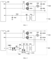
- In the related art, half-bridge topology electromagnetic induction heating cookware detection method is generally adopted in an electromagnetic heating device. As illustrated in
FIG. 1 , each cookware detection cycle lasts about 1 second. Complementary Pulse Width Modulation (PWM) signals are continuously outputted from a pin PWM1 and a pin PWM 2 of acontroller 500, and a switching tube 602 and a switching tube 603 are switched on and off alternately after the signals pass through a half-bridge drive core 601. A current flowing through acoil disk 604 is sampled by acurrent transformer 701, and then converted into a small signal current oftens of milliamperes from a large current signal of tens of amperes. Then, the small signal current is converted into a voltage signal of about 0 V to 5 V after flowing through a load resistor R2. Furthermore, the voltage signal is filtered by a filter circuit composed of aresistor 703 and acapacitor 704, and then is sent to an Analog-to-Digital Converter (ADC) pin of thecontroller 500. A cookware detection current threshold is predetermined in a program of thecontroller 500. When a current value after analog-to-digital conversion is greater than the predetermined threshold, thecontroller 500 is set to a cookware flag bit. In this case, it is determined that cookware is on a current heating furnace surface. When the current value after the analog-to-digital conversion is smaller than the predetermined threshold, the cookware flag bit is cleared by thecontroller 500. In this case, it is determined that no cookware is on the current heating furnace surface. In such manner where it is determined whether there is the cookware through detecting a magnitude of the current flowing through the coil disk, a half-bridge module has power consumption of about forty or fifty watts in the absence of the cookware. The power consumption is borne by the switching tube, which can easily lead to high loss and poor reliability of the switching tube. - The present disclosure aims to solve at least one of the technical problems in the related art. To this end, one embodiments of the present disclosure provide a half-bridge drive heating cookware detection circuit for an electromagnetic heating device, capable of effectively improving reliability of cookware detection while prolonging service life of the electromagnetic heating device.
- In one embodiment of the present disclosure, an electromagnetic heating device is provided.
- In one embodiment of the present disclosure, a cookware detection method for an electromagnetic heating device is provided.
- In one embodiment of the present disclosure, a computer-readable storage medium is provided.
- In one embodiment of the present disclosure, an electromagnetic heating device.
- To achieve the embodiments described above, one embodiment of the present disclosure provides a half-bridge drive heating cookware detection circuit for an electromagnetic heating device. The circuit includes a control module and a pulse cookware detection module. The control module outputs a single pulse cookware detection signal, so as to a half-bridge drive module of the electromagnetic heating device to drive a coil disk to perform a resonant operation through the half-bridge drive module. A pulse detection module is connected to the coil disk and detects a resonant current of the coil disk and generate pulse signals based on the resonant current of the coil disk. The control module is connected to the pulse detection module, and further counts the pulse signals and determine whether cookware is placed on the electromagnetic heating device based on the number of the pulse signals.
- The half-bridge drive heating cookware detection circuit in the embodiments of the present disclosure includes the control module and the pulse cookware detection module. The single pulse cookware detection signal is first outputted to the half-bridge drive module of the electromagnetic heating device from the control module to drive the coil disk to perform the resonant operation through the half-bridge drive module. Because the coil disk is connected to the pulse detection module, the pulse detection module can detect the resonant current of the coil disk and generate the pulse signals based on the resonant current of the coil disk. Then the pulse signals are counted by the pulse detection module to determine whether the cookware is placed on the electromagnetic heating device based on the number of the pulse signals. Therefore, the half-bridge drive heating cookware detection circuit for the electromagnetic heating device can effectively improve the reliability of the cookware detection, and meanwhile prolong the service life of the electromagnetic heating device.
- In some examples of the present disclosure, the pulse detection module includes: a current detection unit connected to the coil disk and configured to detect the resonant current of the coil disk to output a cookware detection current signal; a load unit connected to the current detection unit and configured to generate a voltage detection signal based on the cookware detection current signal; and a zero-crossing voltage comparison unit connected to the load unit and configured to output the pulse signals based on the voltage detection signal.
- In some examples of the present disclosure, the zero-crossing voltage comparison unit includes a current limiting resistor, a comparator, a forward voltage clamp diode and a reverse voltage clamp diode. An end of the current limiting resistor is connected to an end of the load unit. A positive input end of the comparator is connected to another end of the current limiting resistor, a negative input end of the comparator is connected to another end of the load unit, and an output end of the comparator is connected to the control module. The forward voltage clamp diode has an anode connected to the positive input of the comparator and a cathode connected to the negative input end of the comparator. The reverse voltage clamp diode has an anode connected to the negative input end of the comparator and a cathode connected to the positive input end of the comparator.
- In some examples of the present disclosure, the half-bridge drive module includes an upper bridge switching tube and a lower bridge switching tube; and the current detection unit includes a current transformer. The current transformer includes a primary coil and a secondary coil. An end of the primary coil is connected to a node between the upper bridge switching tube and the lower bridge switching tube, and another end of the primary coil is connected to the coil disk. Two ends of the secondary coil are connected to the load unit.
- In some examples of the present disclosure, the load unit includes a first resistor, a second resistor, a first diode and a second diode. An end of the first resistor is connected to one of the two ends of the secondary coil of the current transformer, and another end of the first resistor is connected to the other one of the two ends of the secondary coil of the current transformer. An end of the second resistor is connected to the end of the first resistor. The first diode has an anode connected to the other end of the first resistor and a cathode connected to the other end of the second resistor. The second diode having an anode connected to another end of the second resistor and a cathode connected to the other end of the first resistor.
- In some examples of the present disclosure, the second resistor has a value much smaller than a resistance of the first resistor.
- In some examples of the present disclosure, the single pulse cookware detection signal is outputted from the control module to the half-bridge drive module subsequent to a first predetermined delayed duration, to drive the upper bridge switching tube or the lower bridge switching tube to be switched on. The resonant operation is performed by the coil disk in response to switching on the upper bridge switching tube or the lower bridge switching tube.
- In some examples of the present disclosure, the control module is further configured to determine, when the number of the pulse signals is smaller than a first predetermined value, that the cookware is placed on the electromagnetic heating device.
- To achieve the embodiments described above, one embodiment of the present disclosure provides an electromagnetic heating device. The electromagnetic heating device includes the half-bridge drive heating cookware detection circuit for the electromagnetic heating device according to the embodiments described above.
- In the electromagnetic heating device according to the embodiments of the present disclosure, the function of the half-bridge drive heating cookware detection circuit for the electromagnetic heating device in the embodiments described above can be achieved. Therefore, the reliability of the cookware detection can be effectively improved, and meanwhile the service life of the electromagnetic heating device can be prolonged.
- To achieve the embodiments described above, one embodiment of the present disclosure provides a cookware detection method for an electromagnetic heating device. The cookware detection method includes: outputting a single pulse cookware detection signal to a half-bridge drive module of the electromagnetic heating device, to drive a coil disk to perform a resonant operation through the half-bridge drive module; detecting a resonant current of the coil disk through a pulse detection module, and generating pulse signals based on the resonant current of the coil disk; and counting the pulse signals, and determining whether cookware is placed on the electromagnetic heating device based on the number of the pulse signals.
- In the cookware detection method according to the embodiments of the present disclosure, the single pulse cookware detection signal is first outputted to the half-bridge drive module of the electromagnetic heating device to drive the coil disk to perform the resonant operation through the half-bridge drive module. Furthermore, the resonant current of the coil disk is detected through the pulse detection module, and then the pulse signals are generated based on the resonant current of the coil disk. Then the pulse signals are counted and it is determined whether the cookware is placed on the electromagnetic heating device based on the number of the pulse signals. Therefore, the cookware detection method for the electromagnetic heating device can effectively improve the reliability of the cookware detection, and meanwhile prolong the service life of the electromagnetic heating device.
- In some examples of the present disclosure, the action of determining whether the cookware is placed on the electromagnetic heating device based on the number of the pulse signals includes: determining whether the number of the pulse signals is smaller than a first predetermined value; when yes, determining that the cookware is placed on the electromagnetic heating device; and when no, determining that no cookware is placed on the electromagnetic heating device.
- To achieve the embodiments described above, one embodiment of the present disclosure provides a computer-readable storage medium. The computer-readable storage medium has stored thereon a cookware detection program for an electromagnetic heating device. The cookware detection program for the electromagnetic heating device, when executed by a processor, implements the cookware detection method for the electromagnetic heating device according to the embodiments described above.
- In the computer-readable storage medium according to the embodiments of the present disclosure, the cookware detection program for the electromagnetic heating device is executed by the processor, therefore the reliability of the cookware detection can be effectively improved, and meanwhile the service life of the electromagnetic heating device can be prolonged.
- To achieve the embodiments described above, one embodiment of the present disclosure provides an electromagnetic heating device. The electromagnetic heating device includes: a memory; a processor; and a cookware detection program for an electromagnetic heating device. The cookware detection program is stored on the memory and is executable on the processor. The cookware detection program, when executed by the processor, implements the cookware detection method for the electromagnetic heating device according to the embodiments described above.
- In the electromagnetic heating device according to the embodiments of the present disclosure, the cookware detection program stored on the memory is executed by the processor, therefore the reliability of the cookware detection can be effectively improved, and meanwhile the service life of the electromagnetic heating device can be prolonged.
- Additional aspects and advantages of the embodiments of present disclosure will be provided at least in part in the following description, or will become apparent in part from the following description, or can be learned from the practice of the embodiments of the present disclosure.
- These and other aspects and advantages of embodiments of the present disclosure will become apparent and more readily appreciated from the following descriptions made with reference to the accompanying drawings, in which:
-
FIG. 1 is a schematic diagram of a half-bridge topology electromagnetic induction heating cookware detection circuit for an electromagnetic heating device in the related art. -
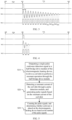
FIG. 2 is a schematic diagram of a half-bridge drive heating cookware detection circuit for an electromagnetic heating device according to embodiments of the present disclosure. -
FIG. 3 is a schematic diagram of a cookware detection signal according to an embodiment of the present disclosure. -
FIG. 4 is a schematic diagram of a cookware detection signal according to another embodiment of the present disclosure. -
FIG. 5 is a flowchart of a cookware detection method for an electromagnetic heating device according to embodiments of the present disclosure. - The embodiments of the present disclosure will be described in detail below with reference to examples thereof as illustrated in the accompanying drawings, throughout which same or similar elements, or elements having same or similar functions, are denoted by same or similar reference numerals. The embodiments described below with reference to the drawings are illustrative only, and are intended to explain rather than limit the present disclosure.
- A half-bridge drive heating cookware detection circuit, a heating device, a cookware detection method, and a storage medium according to the embodiments of the present disclosure are described below with reference to the accompanying drawings.
-
FIG. 2 is a schematic diagram of a half-bridge drive heating cookware detection circuit for an electromagnetic heating device according to an embodiment of the present disclosure. - As illustrated in
FIG. 2 , a half-bridge drive heating cookware detection circuit of an electromagnetic heating device according to embodiments of the present disclosure includes acontrol module 100 and a pulsecookware detection module 300. - The
control module 100 is configured to output a single pulse cookware detection signal to a half-bridge drive module of the electromagnetic heating device to drive a coil disk to perform a resonance operation through the half-bridge drive module. Thepulse detection module 300 is connected to the coil disk, and is configured to detect a resonant current of the coil disk and generate pulse signals based on the resonant current of the coil disk. Thecontrol module 100 is connected to thepulse detection module 300, and is further configured to count the pulse signals and determine, whether cookware is placed on the electromagnetic heating device based on the number of the pulse signals. - In one embodiment, referring to
FIG. 2 , two PWM pins, i.e., PWM1 and PWM2 are disposed on thecontrol module 100 respectively. In this embodiment, the single pulse cookware detection signal is outputted, through PWM2, from thecontrol module 100 to the half-bridge drive module 200 of the electromagnetic heating device, therefore thecoil disk 204 in the half-bridge drive module 200 can perform the resonant operation. - In one embodiment, as illustrated in
FIG. 3 , a W10 represents a single pulse cookware detection signal output from the PWM2, and a W11 represents a resonant signal of thecoil disk 204. It can be seen fromFIG. 3 that, thecoil disk 204, driven by the single pulse cookware detection signal, can produce LC resonance with a capacitor 205 and a capacitor 206 to generate a resonant signal. Due to internal resistance consumption, the resonant signal of thecoil disk 204 will become weaker and weaker until it disappears. - It can be seen from
FIG. 2 that, thepulse detection module 300 is connected to thecoil disk 204, and when the resonance signal is generated by thecoil disk 204, thepulse detection module 300 can detect the resonant current of thecoil disk 204, and generate the pulse signals based on the resonant current of thecoil disk 204. A W12 signal as illustrated inFIG. 3 is pulse signals generated by thepulse detection module 300 based on the resonant current of thecoil disk 204. - It can be understood that, the
pulse detection module 300 can detect the resonant current of thecoil disk 204 and generate the pulse signals corresponding to the resonant current, and then the pulse signals are counted through thecontrol module 100 connected to thepulse detection module 300. After the number of the pulse signals is obtained, it is determined whether the cookware is placed on the electromagnetic heating device based on the number of the pulse signals. - In some embodiments of the present disclosure, as illustrated in
FIG. 2 , thepulse detection module 300 includes acurrent detection unit 301, aload unit 3020, and a zero-crossingvoltage comparison unit 303. - The
current detection unit 301 is connected to thecoil disk 204, and is configured to detect the resonant current of thecoil disk 204 to output a cookware detection current signal. Theload unit 3020 is connected to thecurrent detection unit 301, and is configured to generate a voltage detection signal based on the cookware detection current signal. The zero-crossingvoltage comparison unit 303 is connected to theload unit 3020, and is configured to output the pulse signals based on the voltage detection signal. - In this embodiment, as illustrated in
FIG. 2 , the half-bridge drive module 200 includes an upper bridge switching tube 202 and a lowerbridge switching tube 203. Thecurrent detection unit 301 includes a current transformer. An end of the primary coil of the current transformer is connected to a node between the upper bridge switching tube 202 and the lowerbridge switching tube 203, another end of the primary coil of the current transformer is connected to thecoil disk 204, and two ends of the secondary coil of the current transformer are connected to theload unit 3020. - In one embodiment, by setting the
current detection unit 301 including the current transformer, through the current transformer, a ten-ampere large current signal flowing through thecoil disk 204 can be converted into a small current digital signal of tens of milliamperes, and an effect of signal isolation is achieved. After the small current digital signal is obtained by thecurrent detection unit 301, the signal passes through theload unit 3020 to generate a corresponding voltage detection signal. The voltage detection signal is then compared by passing through the zero-crossingvoltage comparison unit 303 to obtain pulse signals corresponding to the voltage detection signal. Furthermore, the pulse signals are obtained by thecontroller 100. - In some examples, as illustrated in
FIG. 2 , theload unit 3020 includes a first resistor R1, a second resistor R2, a first diode D1, and a second diode D2. - An end of the first resistor R1 is connected to one of the two ends of the secondary coil of the current transformer, and another end of the first resistor R1 is connected to another of the two ends of the secondary coil of the current transformer. The one end of the second resistor R2 is connected to the one end of the first resistor R1. The first diode D1 having an anode connected to the other end of the first resistor R1 and a cathode connected to the other end of the second resistor R2. The second diode D2 having an anode connected to another end of the second resistor R2 and a cathode connected to the other end of the first resistor R1.
- In one embodiment, a combination of the second resistor R2, the first diode D1, and the second diode D2 may serve as a second load unit, and the first resistor R1 may serve as a first load unit. The second resistor R2 has a value much smaller than a resistance of the first resistor R1. In one embodiment, a resistance of the first resistor R1 ranges from 50 Ohm to 5000 Ohm, and a resistance of the second resistor ranges from 1 Ohm to 50 Ohm. When the resonance current generated by the
coil disk 204 is relatively small, for example, the resonance current is smaller than 1 ampere, the signal is converted into the voltage signal through the first load unit. When the resonance current generated by thecoil disk 204 is relatively large, for example, the resonance current is greater than 1 ampere, the signal is converted into the voltage signal through the second load unit. - In some examples of the present disclosure, as illustrated in
FIG. 2 , the zero-crossingvoltage comparison unit 303 includes a current limiting resistor R3, a comparator CMP1, a forward voltage clamping diode D4, and a reverse voltage clamp diode D5. - An end of the current limiting resistor R3 is connected to one end Va of the
load unit 3020. A positive input end of the comparator CMP1 is connected to another end of the current limiting resistor R3, a negative input end of the comparator CMP1 is connected to another end Vb of theload unit 3020, and an output end of the comparator CMP1 is connected to thecontrol module 100. The forward voltage clamp diode D4 has an anode connected to the positive input end of the comparator CMP1, and a cathode connected to the negative input end of the comparator CMP1. The reverse voltage clamp diode D5 having an anode connected to the negative input end of the comparator CMP1 and a cathode connected to the positive input end of the comparator CMP1. - In one embodiment, referring to
FIG. 2 , the zero-crossingvoltage comparison unit 303 includes two voltage clamp diodes, i.e., a forward voltage clamp diode D4 and a reverse voltage clamp diode D5, respectively. After the current signal passes through theload unit 3020 and is converted into the voltage signal, the voltage signal may be detected from both ends of theload unit 3020, i.e., the end Va and the end Vb. When a voltage difference between the two ends of theload unit 3020 is greater than a first predetermined voltage, such as 0.7 volts, a voltage of an in-phase input end may be limited to 0.7 volts through the forward voltage clamp diode D4; and when a voltage difference between the two ends of theload unit 3020 is greater than a second predetermined voltage, such as negative 0.7 volts, a voltage of an in-phase input end may be limited to negative 0.7 volts through the reverse voltage clamp diode D5. Thus, the in-phase end of the comparator CMP1 can be protected. When the voltage of the in-phase input end of the comparator CMP1 is higher than that of an antiphase input end, an output of the comparator CMP1 is at a high level; and when the voltage of the in-phase input end of the comparator CMP1 is lower than that of the antiphase input end thereof, an output of the comparator CMP1 is at a low level. - In some embodiments of the present disclosure, as illustrated in
FIG. 2 , the single pulse cookware detection signal is outputted from thecontrol module 100 to the half-bridge drive module 200 subsequent to a first predetermined delayed duration, to drive the upper bridge switching tube 202 or the lowerbridge switching tube 203 to be switched on. The resonant operation is performed by thecoil disk 204 in response to switching on the upper bridge switching tube 202 or the lowerbridge switching tube 203. - In one embodiment, referring to
FIG. 2 andFIG. 3 , in response to no cookware being placed on thecoil disk 204, the single pulse cookware detection signal W10 is outputted, subsequent to a first predetermined delayed duration T10, from thecontrol module 100 to the half-bridge drive module 200 at a time point t11 through the PWM 2 pin, to drive the upper bridge switching tube 202 or the lowerbridge switching tube 203 to be switched on. For example, as illustrated inFIG. 3 , the single pulse cookware detection signal W10 is a high-level cookware detection pulse, and a high-level pulse time period is 1 microsecond to 10 microseconds, which is shown as a duration Td inFIG. 3 . After the lowerbridge switching tube 203 is switched on for the duration Td, thecoil disk 204 produces the LC resonance with the resonant capacitor 205 and the resonant capacitor 206, and the resonant signal is shown as the waveform signal W11 inFIG. 3 . - When the
coil disk 204 has a positive current, a positive current is also outputted from the current transformer, and then passes through a first current load module R1 or a secondcurrent load module 302 to be converted into the voltage signal. In this case, there are positive voltages at a node Va and a node Vb. When the voltages at the node Va and the node Vb exceed the first predetermined voltage, such as 0.7 V, the voltage of the in-phase input end of the comparator CMP1 is clamped to 0.7 V by the diode D4, which has an effect of protecting the in-phase input end. When the voltage of the in-phase input end of the comparator is higher than that of the antiphase input end thereof, an output of the comparator CMP1 is at a high level. - When the
coil disk 204 has a negative current, a negative current is also outputted from the current transformer, and then passes through the first current load module R1 or the secondcurrent load module 302 to be converted into the voltage signal. In this case, there are positive voltages at the node Va and the node Vb. When the voltages at the node Va and the node Vb exceed the second predetermined voltage, such as 0.7 V, the voltage of the in-phase input end of the comparator CMP1 is clamped to the negative 0.7 V by the diode D4, which has the effect of protecting the in-phase input end. When the voltage of the in-phase input end of the comparator is lower than that of the antiphase input end thereof, an output of the comparator CMP1 is at a low level. - The above description is an operation process of a resonant cycle of the
coil disk 204, and the operation process described above is repeated later. Due to no cookware being placed on thecoil disk 204, energy of thecoil disk 204 in the half-bridge drive module 200 is mainly consumed by the internal resistance of thecoil disk 204. Thecoil disk 204 has a relatively small internal resistance at a few milliohms level, therefore energy loss of thecoil disk 204 is small, and the energy is depleted only when the current of thecoil disk 204 is reduced to 0 ampere after many resonant cycles. Correspondingly, numbers of pulses are outputted from the comparator CMP 1. As illustrated inFIG. 3 , the resonant current of thecoil disk 204 is reduced to 0 ampere after 15 cycles, 15 pulse signals are outputted from the comparator CMP1 as shown in a waveform signal W12. In this embodiment, thecontrol module 100 is further configured to determine, when the number of the pulse signals is smaller than a first predetermined value, that the cookware is placed on the electromagnetic heating device. For example, when the first predetermined value is 8, it can be determined that no cookware is placed on the electromagnetic device when the number of the pulse signals is smaller than the first predetermined value. - When the cookware is placed on the
coil disk 204, as illustrated inFIG. 2 andFIG. 4 , W20 represents a waveform signal of a PWM2 pin outputted from thecontrol module 100, W21 represents a current waveform of thecoil disk 204, and W22 represents a pulse waveform outputted from the zero-crossingvoltage comparison unit 303. A specific operation process may refer to the above-mentioned embodiments where no cookware is placed. In contrast, since the cookware is placed on thecoil disk 204, the energy of thecoil disk 204 is mainly consumed by the cookware. Moreover, an equivalent resistance of the cookware is at a few ohms level much larger than the internal resistance of thecoil disk 204 at a few milliohms level, therefore the current of thecoil disk 204 can be reduced to 0 ampere only after several resonant cycles to deplete the energy. Correspondingly, small numbers of pulses are outputted from the comparator CMP 1. As illustrated inFIG. 4 , the resonant current of thecoil disk 204 is reduced to 0 ampere after 3 cycles in the waveform W21, and three pulses are outputted from the comparator CMP 1 as shown in the waveform signal W22. In this embodiment, thecontrol module 100 is further configured to determine, when the number of the pulse signals is smaller than a first predetermined value, that the cookware is placed on the electromagnetic heating device. For example, when the first predetermined value is 8, it can be determined that the cookware is placed on the electromagnetic device when the number of the pulse signals is smaller than the first predetermined value. - In one embodiment, during cookware detection, whether a current cookware flag bit is zero or not can be first judged through the controller. When the current cookware flag bit is zero, an operation of cookware detection can be performed through the embodiments described above. In response to determining that the cookware is placed on the electromagnetic heating device through the embodiments described above, the current cookware flag bit is 1. In response to determining by the controller that the current cookware flag bit is not zero, it is identified that the cookware is placed on the current electromagnetic heating device.
- To sum up, in the half-bridge drive heating cookware detection circuit for the electromagnetic heating device according to the embodiments described above, during the cookware detection, the controller can only output a short pulse with a pulse width of about 1 microsecond to 10 microseconds to the PWM2, and energy from a position of a power supply supplying power is obtained by the lower bridge switching tube during the time period. Then the coil disk resonates with the resonant capacitor, and the resonant cycle is obtained through the number of pulses output from the zero-crossing
voltage comparison unit 303 to realize the cookware detection. Therefore, the switching tube in the half-bridge drive heating detection cookware circuit is only switched on for a very short duration, the upper bridge switching tube is not switched on. Therefore, the switching tube loss of the half-bridge drive heating detection cookware circuit during the cookware detection is greatly reduced. In this way, the reliability of the cookware detection can be effectively improved, and meanwhile the service life of the electromagnetic heating device is prolonged. - Further, the present disclosure provides an electromagnetic heating device. The electromagnetic heating device includes the half-bridge drive heating cookware detection circuit for the electromagnetic heating device according to the embodiments described above.
- In the electromagnetic heating device according to the embodiments of the present disclosure, the function of the half-bridge drive heating cookware detection circuit for the electromagnetic heating device in the embodiments described above can be achieved. Therefore, the reliability of the cookware detection can be effectively improved, and meanwhile the service life of the electromagnetic heating device can be prolonged.
-
FIG. 5 is a flowchart of a cookware detection method for an electromagnetic heating device according to embodiments of the present disclosure. - Further, the present disclosure provides a cookware detection method for an electromagnetic heating device. As illustrated in
FIG. 5 , the cookware detection method in this embodiment includes the following steps: step S10, outputting a single pulse cookware detection signal to a half-bridge drive module of the electromagnetic heating device, to drive a coil disk to perform a resonant operation through the half-bridge drive module; step S20, detecting a resonant current of the coil disk through a pulse detection module, and generating pulse signals based on the resonant current of the coil disk; and step S30, counting the pulse signals, and determining whether cookware is placed on the electromagnetic heating device based on the number of the pulse signals. - In one embodiment, referring to
FIG. 2 andFIG. 5 , two PWM pins, i.e., PWM1 and PWM2 are disposed on thecontrol module 100 respectively. In this embodiment, the single pulse cookware detection signal is outputted, through the pin PWM2, to the half-bridge drive module 200 of the electromagnetic heating device from thecontrol module 100, therefore thecoil disk 204 in the half-bridge drive module 200 can perform the resonant operation. - In one embodiment, as illustrated in
FIG. 3 , a W10 represents a single pulse cookware detection signal outputted from the PWM2, and a W11 represents a resonant signal of thecoil disk 204. It can be seen fromFIG. 3 that, thecoil disk 204, driven by the single pulse cookware detection signal, can produce LC resonance with a capacitor 205 and a capacitor 206 to generate a resonant signal. Due to internal resistance consumption, the resonant signal of thecoil disk 204 will become weaker and weaker until it disappears. - It can be seen from
FIG. 2 that, thepulse detection module 300 is connected to thecoil disk 204, and when the resonance signal is generated by thecoil disk 204, thepulse detection module 300 can detect the resonant current of thecoil disk 204, and generate the pulse signals based on the resonant current of thecoil disk 204. A signal W12 as illustrated inFIG. 3 is pulse signals generated by thepulse detection module 300 based on the resonant current of thecoil disk 204. - It can be understood that, the
pulse detection module 300 can detect the resonant current of thecoil disk 204 and generate the pulse signals corresponding to the resonant current, and then the pulse signals are counted by using thecontrol module 100 connected to thepulse detection module 300. After the number of the pulse signals is obtained, it is determined whether cookware is placed on the electromagnetic heating device based on the number of the pulse signals. - In some examples of the present disclosure, the action of determining whether the cookware is placed on the electromagnetic heating device based on the number of the pulse signals includes: determining whether the number of the pulse signals is smaller than a first predetermined value; determining, in response to determining that the number of the pulse signals is smaller than the first predetermined value, that the cookware is placed on the electromagnetic heating device; and determining, in response to determining that the number of the pulse signals is greater than or equal to the first predetermined value, that no cookware is placed on the electromagnetic heating device.
- It should be noted that, other specific implementations of the cookware detection method for the electromagnetic heating device according to the embodiments of the present disclosure may refer to the specific embodiments of the implementation method of the half-bridge drive heating cookware detection circuit for the electromagnetic heating device in the embodiments described above.
- To sum up, in the cookware detection method for the electromagnetic heating device according to the embodiments described above, during the cookware detection, the controller can only output a short pulse with a pulse width of about 1 microsecond to 10 microseconds to the PWM2, and energy from a position of a power supply supplying power is obtained by the lower bridge switching tube during the time period. Then the coil disk resonates with the resonant capacitor, and the resonant cycle is obtained through the number of pulses output from the zero-crossing
voltage comparison unit 303 to realize the cookware detection. Therefore, the switching tube in the half-bridge drive heating detection cookware circuit is only switched on for a very short duration, the upper bridge switching tube is not switched on, and thus the switching tube loss of the half-bridge drive heating detection cookware circuit during the cookware detection is greatly reduced. In this way, the reliability of the cookware detection can be effectively improved, and meanwhile the service life of the electromagnetic heating device is prolonged. - Further, the present disclosure provides a computer-readable storage medium. The computer-readable storage medium has stored thereon a cookware detection program for an electromagnetic heating device. The cookware detection program for the electromagnetic heating device, when executed by a processor, implements the cookware detection method for the electromagnetic heating device according to the embodiments described above.
- In the computer-readable storage medium according to the embodiments of the present disclosure, the cookware detection program for the electromagnetic heating device is executed by the processor, therefore the reliability of the cookware detection can be effectively improved, and meanwhile the service life of the electromagnetic heating device can be prolonged.
- Further, the present disclosure provides an electromagnetic heating device. The electromagnetic heating device includes: a memory; a processor; and a cookware detection program for an electromagnetic heating device. The cookware detection program is stored on the memory and executable on the processor. The cookware detection program, when executed by the processor, implements the cookware detection method for the electromagnetic heating device according to the embodiments described above.
- In the electromagnetic heating device according to the embodiments of the present disclosure, the cookware detection program for the electromagnetic heating device stored on the memory is executed by the processor, therefore the reliability of the cookware detection can be effectively improved, and meanwhile the service life of the electromagnetic heating device can be prolonged.
- The embodiments of the present disclosure are described in detail above with reference to the accompanying drawings, but the present disclosure is not limited to the above embodiments, and various changes may also be made within the scope of knowledge possessed by those skilled in the art and without departing from the spirit of the present disclosure.
Claims (13)
- A half-bridge drive heating cookware detection circuit for an electromagnetic heating device, wherein the half-bridge drive heating cookware detection circuit comprising:a control module outputting a single pulse cookware detection signal to a half-bridge drive module of the electromagnetic heating device, so as to drive a coil disk to perform a resonant operation through the half-bridge drive module; anda pulse cookware detection module connected to the coil disk and detecting a resonant current of the coil disk, and the pulse detection module generating pulse signals based on the resonant current of the coil disk,wherein the control module is connected to the pulse detection module, and the control module further counts the pulse signals and determine whether the cookware is placed on the electromagnetic heating device based on a number of the pulse signals.
- The half-bridge drive heating cookware detection circuit for the electromagnetic heating device according to claim 1, wherein the pulse detection module comprises:a current detection unit connected to the coil disk and configured to detect the resonant current of the coil disk to output a cookware detection current signal;a load unit connected to the current detection unit and configured to generate a voltage detection signal based on the cookware detection current signal; anda zero-crossing voltage comparison unit connected to the load unit and configured to output the pulse signals based on the voltage detection signal.
- The half-bridge drive heating cookware detection circuit for the electromagnetic heating device according to claim 2, wherein the zero-crossing voltage comparison unit comprises:a current limiting resistor, an end of the current limiting resistor being connected to an end of the load unit;a comparator, a positive input end of the comparator being connected to an other end of the current limiting resistor, a negative input end of the comparator being connected to an other end of the load unit, and an output end of the comparator being connected to the control module;a forward voltage clamp diode having an anode connected to the positive input of the comparator and a cathode connected to the negative input end of the comparator; anda reverse voltage clamp diode having an anode connected to the negative input end of the comparator and a cathode connected to the positive input end of the comparator.
- The half-bridge drive heating cookware detection circuit for the electromagnetic heating device according to claim 2, wherein:the half-bridge drive module comprises an upper bridge switching tube and a lower bridge switching tube; andthe current detection unit comprises a current transformer comprising:a primary coil, an end of the primary coil being connected to a node between the upper bridge switching tube and the lower bridge switching tube, and an other end of the primary coil being connected to the coil disk; anda secondary coil, two ends of the secondary coil being connected to the load unit.
- The half-bridge drive heating cookware detection circuit for the electromagnetic heating device according to claim 4, wherein the load unit comprises:a first resistor, an end of the first resistor being connected to one of the two ends of the secondary coil of the current transformer, and an other end of the first resistor being connected to another of the two ends of the secondary coil of the current transformer;a second resistor, an end of the second resistor being connected to the end of the first resistor;a first diode having an anode connected to the other end of the first resistor and a cathode connected to an other end of the second resistor; anda second diode having an anode connected to the other end of the second resistor and a cathode connected to the other end of the first resistor.
- The half-bridge drive heating cookware detection circuit for the electromagnetic heating device according to claim 5, wherein the second resistor has a value much smaller than a resistance of the first resistor.
- The half-bridge drive heating cookware detection circuit for the electromagnetic heating device according to claim 4, wherein:the single pulse cookware detection signal is outputted from the control module to the half-bridge drive module subsequent to a first predetermined delayed duration, so as to drive the upper bridge switching tube or the lower bridge switching tube to be switched on; andthe resonant operation is performed by the coil disk in response to switching on the upper bridge switching tube or the lower bridge switching tube.
- The half-bridge drive heating cookware detection circuit for the electromagnetic heating device according to any one of claims 1 to 7, wherein the control module is further configured to determine, when the number of the pulse signals is smaller than a first predetermined value, the cookware is placed on the electromagnetic heating device.
- An electromagnetic heating device, comprising the half-bridge drive heating cookware detection circuit for the electromagnetic heating device according to any one of claims 1 to 8.
- A cookware detection method for an electromagnetic heating device, wherein the cookware detection method comprising:outputting a single pulse cookware detection signal to a half-bridge drive module of the electromagnetic heating device, so as to drive a coil disk to perform a resonant operation through the half-bridge drive module;detecting a resonant current of the coil disk through a pulse detection module, and generating pulse signals based on the resonant current of the coil disk; andcounting the pulse signals, and determining whether the cookware is placed on the electromagnetic heating device based on the number of the pulse signals.
- The cookware detection method for the electromagnetic heating device according to claim 10, wherein the determining whether the cookware is placed on the electromagnetic heating device based on the number of the pulse signals comprises:determining whether the number of the pulse signals is smaller than a first predetermined value;when yes, determining that the cookware is placed on the electromagnetic heating device; andwhen no, determining that no cookware is placed on the electromagnetic heating device.
- A computer-readable storage medium, having stored thereon a cookware detection program for an electromagnetic heating device,
wherein the cookware detection program for the electromagnetic heating device, when executed by a processor, implements a cookware detection method for the electromagnetic heating device according to claim 10 or 11. - An electromagnetic heating device, comprising:a memory;a processor; anda cookware detection program for an electromagnetic heating device, the cookware detection program being stored on the memory and being executable on the processor,wherein the cookware detection program, when executed by the processor, implements a cookware detection method for the electromagnetic heating device according to claim 10 or 11.
Applications Claiming Priority (2)
| Application Number | Priority Date | Filing Date | Title |
|---|---|---|---|
| CN202011593061.5A CN114680632A (en) | 2020-12-29 | 2020-12-29 | Half-bridge driving heating pot detection circuit, heating equipment, pot detection method and storage medium |
| PCT/CN2021/139560 WO2022143248A1 (en) | 2020-12-29 | 2021-12-20 | Half-bridge-drive heating cookware detection circuit, heating device, cookware detection method, and storage medium |
Publications (2)
| Publication Number | Publication Date |
|---|---|
| EP4258815A1 true EP4258815A1 (en) | 2023-10-11 |
| EP4258815A4 EP4258815A4 (en) | 2024-05-29 |
Family
ID=82132684
Family Applications (1)
| Application Number | Title | Priority Date | Filing Date |
|---|---|---|---|
| EP21913989.6A Pending EP4258815A4 (en) | 2020-12-29 | 2021-12-20 | Half-bridge-drive heating cookware detection circuit, heating device, cookware detection method, and storage medium |
Country Status (4)
| Country | Link |
|---|---|
| US (1) | US20240057811A1 (en) |
| EP (1) | EP4258815A4 (en) |
| CN (1) | CN114680632A (en) |
| WO (1) | WO2022143248A1 (en) |
Families Citing this family (5)
| Publication number | Priority date | Publication date | Assignee | Title |
|---|---|---|---|---|
| CN114698169A (en) * | 2020-12-29 | 2022-07-01 | 佛山市顺德区美的电热电器制造有限公司 | Electromagnetic heating equipment, pan inspection method and system, storage medium |
| CN118250849A (en) * | 2022-12-22 | 2024-06-25 | 佛山市顺德区美的电热电器制造有限公司 | Load detection circuit, load detection method and household appliance |
| CN119922774B (en) * | 2023-10-31 | 2026-03-17 | 佛山市顺德区美的电热电器制造有限公司 | Electromagnetic heating circuits, control methods, devices, and electrical equipment |
| CN119922775B (en) * | 2023-10-31 | 2026-03-17 | 佛山市顺德区美的电热电器制造有限公司 | Electromagnetic heating circuits, control methods, devices, and electrical equipment |
| CN120499884B (en) * | 2024-08-20 | 2025-11-14 | 中山市一谷电器科技有限公司 | Electromagnetic heating power regulating method, coil panel equipment, control device and storage medium |
Family Cites Families (20)
| Publication number | Priority date | Publication date | Assignee | Title |
|---|---|---|---|---|
| US7976718B2 (en) * | 2003-12-30 | 2011-07-12 | Akrion Systems Llc | System and method for selective etching of silicon nitride during substrate processing |
| US8174855B2 (en) * | 2005-10-12 | 2012-05-08 | International Rectifier Corporation | Power factor correction integrated circuit with critical conduction mode |
| CN101437333A (en) * | 2007-11-16 | 2009-05-20 | 青岛雅合科技发展有限公司 | Integrated module for digital high frequency switch electromagnetic heating power supply system |
| CN101909375B (en) * | 2009-06-08 | 2012-11-28 | 深圳市鑫汇科科技有限公司 | High-power electromagnetic oven circuit based on SoC (System On Chip) chip |
| CN103501555B (en) * | 2013-09-25 | 2015-02-18 | 电子科技大学 | Digital phase locking and frequency tracking electromagnetic induction heating power controller |
| CN104754789B (en) * | 2013-12-25 | 2016-08-17 | 美的集团股份有限公司 | The electromagnetic heater of Intelligent Recognition pan size and control method thereof |
| CN204634072U (en) * | 2015-03-04 | 2015-09-09 | 佛山市顺德区美的电热电器制造有限公司 | The zero passage of electromagnetic heating system and breaker in middle pipe thereof opens checkout gear |
| JP6920582B2 (en) * | 2016-08-23 | 2021-08-18 | パナソニックIpマネジメント株式会社 | Induction heating device |
| CN206585777U (en) * | 2017-02-08 | 2017-10-24 | 诺思泰(天津)科技有限公司 | A kind of half-bridge electromagnetic oven circuit |
| CN107315198A (en) * | 2017-06-19 | 2017-11-03 | 浙江绍兴苏泊尔生活电器有限公司 | induction cooker and cooker detection method |
| CN109324347B (en) * | 2017-07-31 | 2020-04-10 | 佛山市顺德区美的电热电器制造有限公司 | Pot detection method and device for induction cooker |
| KR101999511B1 (en) * | 2017-08-04 | 2019-07-11 | 엘지전자 주식회사 | Induction heat cooking apparatus and operating method thereof |
| CN109412534A (en) * | 2017-08-16 | 2019-03-01 | 佛山市顺德区美的电热电器制造有限公司 | Detection circuit, heating platform, cooking apparatus and appliance identification method |
| KR102016219B1 (en) * | 2017-09-29 | 2019-08-29 | 엘지전자 주식회사 | Induction heating and wireless power transferring device having improved target detection algorithm |
| US11064575B2 (en) * | 2017-10-19 | 2021-07-13 | Lg Electronics Inc. | Induction heating device having improved target object detection accuracy and induction heating system including the same |
| KR102641089B1 (en) * | 2018-11-08 | 2024-02-26 | 엘지전자 주식회사 | Single pulse pre-test method for improving vessel detection accuracy |
| CN111385930B (en) * | 2018-12-29 | 2022-04-29 | 佛山市顺德区美的电热电器制造有限公司 | Electromagnetic heating appliance control method, device and electromagnetic heating appliance |
| CN111901914B (en) * | 2019-05-05 | 2022-11-22 | 佛山市顺德区美的电热电器制造有限公司 | Control circuit and method of electromagnetic heating appliance and electromagnetic heating appliance |
| CN210717692U (en) * | 2019-11-16 | 2020-06-09 | 佛山市嘉士德电器科技有限公司 | Induction cooker with no regional detection pan and automatic identification heating function |
| US12446118B2 (en) * | 2022-01-21 | 2025-10-14 | The Vollrath Company, L.L.C. | Induction warmer station |
-
2020
- 2020-12-29 CN CN202011593061.5A patent/CN114680632A/en active Pending
-
2021
- 2021-12-20 US US18/270,120 patent/US20240057811A1/en active Pending
- 2021-12-20 WO PCT/CN2021/139560 patent/WO2022143248A1/en not_active Ceased
- 2021-12-20 EP EP21913989.6A patent/EP4258815A4/en active Pending
Also Published As
| Publication number | Publication date |
|---|---|
| US20240057811A1 (en) | 2024-02-22 |
| WO2022143248A1 (en) | 2022-07-07 |
| EP4258815A4 (en) | 2024-05-29 |
| CN114680632A (en) | 2022-07-01 |
Similar Documents
| Publication | Publication Date | Title |
|---|---|---|
| US20240057811A1 (en) | Cookware detection circuit using half-bridge drive heating, heating device, cookware detection method, and storage medium | |
| TWI479791B (en) | On/off mode optical coupler feedback for isolated switching power supply regulation | |
| EP1215808B1 (en) | A power supply circuit and method thereof to detect demagnitization of the power supply | |
| US10158298B2 (en) | Communication circuit for flyback power converter with synchronous rectifier | |
| US20160172841A1 (en) | Protection mode control circuit, switch control circuit including the protection mode control circuit and power supply device including the switch control circuit | |
| KR20150095180A (en) | Switch control circuit and resonant converter comprising thereof | |
| CN103715898B (en) | Feedback voltage sample circuit, feedback voltage blanking circuit and method | |
| JP2019047621A (en) | Semiconductor device for power supply control, power supply device, and discharge method of x capacitor | |
| KR20100000667A (en) | Switch control device and converter comprising the same | |
| CN1965466A (en) | Switching-mode power supply | |
| CN104052290A (en) | Switching Power Converter with Secondary-to-Primary Messaging | |
| JP4528616B2 (en) | Driver for gas discharge lamp | |
| CN108880523A (en) | SCR control device and method | |
| CN217445049U (en) | Power-on protection circuit and electronic equipment | |
| JP2021097340A (en) | Semiconductor driving device and power conversion device | |
| JP2005051991A (en) | Control unit of duty cycle in half-bridge type dc-dc converter using current mode control | |
| JP4919858B2 (en) | Switching power supply | |
| JP7044310B2 (en) | Power supply device with duty ratio limiting circuit, duty ratio limiting circuit and its operation method | |
| JP2020010414A (en) | Switching power supply and switching power supply control circuit | |
| KR20210123045A (en) | Method for discharging capacitor of resonant power conversion apparatus at initiating of operation and resonant power conversion apparatus thereof | |
| KR101970870B1 (en) | Gate voltage control device | |
| CN108123429B (en) | Overvoltage protection circuit | |
| JP2921225B2 (en) | Piezo element drive circuit | |
| US12573962B2 (en) | Isolated power supply control circuit and isolated power supply | |
| KR20210148340A (en) | Pre-start control circuit for switching power converters |
Legal Events
| Date | Code | Title | Description |
|---|---|---|---|
| STAA | Information on the status of an ep patent application or granted ep patent |
Free format text: STATUS: THE INTERNATIONAL PUBLICATION HAS BEEN MADE |
|
| PUAI | Public reference made under article 153(3) epc to a published international application that has entered the european phase |
Free format text: ORIGINAL CODE: 0009012 |
|
| STAA | Information on the status of an ep patent application or granted ep patent |
Free format text: STATUS: REQUEST FOR EXAMINATION WAS MADE |
|
| 17P | Request for examination filed |
Effective date: 20230703 |
|
| AK | Designated contracting states |
Kind code of ref document: A1 Designated state(s): AL AT BE BG CH CY CZ DE DK EE ES FI FR GB GR HR HU IE IS IT LI LT LU LV MC MK MT NL NO PL PT RO RS SE SI SK SM TR |
|
| DAV | Request for validation of the european patent (deleted) | ||
| DAX | Request for extension of the european patent (deleted) | ||
| A4 | Supplementary search report drawn up and despatched |
Effective date: 20240425 |
|
| RIC1 | Information provided on ipc code assigned before grant |
Ipc: F24C 7/08 20060101ALI20240419BHEP Ipc: A47J 36/24 20060101ALI20240419BHEP Ipc: H05B 6/06 20060101AFI20240419BHEP |